EP3309264A1 - Hybridkomponente und verfahren zur herstellung - Google Patents
Hybridkomponente und verfahren zur herstellung Download PDFInfo
- Publication number
- EP3309264A1 EP3309264A1 EP17185404.5A EP17185404A EP3309264A1 EP 3309264 A1 EP3309264 A1 EP 3309264A1 EP 17185404 A EP17185404 A EP 17185404A EP 3309264 A1 EP3309264 A1 EP 3309264A1
- Authority
- EP
- European Patent Office
- Prior art keywords
- substrate
- rim
- bore
- grain size
- average grain
- Prior art date
- Legal status (The legal status is an assumption and is not a legal conclusion. Google has not performed a legal analysis and makes no representation as to the accuracy of the status listed.)
- Withdrawn
Links
- 238000004519 manufacturing process Methods 0.000 title description 6
- 239000000758 substrate Substances 0.000 claims abstract description 164
- 238000000034 method Methods 0.000 claims abstract description 36
- 238000003466 welding Methods 0.000 claims abstract description 27
- 238000010438 heat treatment Methods 0.000 claims description 22
- 239000000956 alloy Substances 0.000 claims description 15
- 229910045601 alloy Inorganic materials 0.000 claims description 15
- 238000003754 machining Methods 0.000 claims description 15
- 239000000463 material Substances 0.000 description 22
- 230000035882 stress Effects 0.000 description 14
- 239000000203 mixture Substances 0.000 description 6
- 230000008569 process Effects 0.000 description 5
- 230000032683 aging Effects 0.000 description 4
- 238000004663 powder metallurgy Methods 0.000 description 4
- 239000000356 contaminant Substances 0.000 description 3
- 239000002184 metal Substances 0.000 description 3
- OKTJSMMVPCPJKN-UHFFFAOYSA-N Carbon Chemical compound [C] OKTJSMMVPCPJKN-UHFFFAOYSA-N 0.000 description 2
- 238000004458 analytical method Methods 0.000 description 2
- 230000008901 benefit Effects 0.000 description 2
- 230000015572 biosynthetic process Effects 0.000 description 2
- 229910052799 carbon Inorganic materials 0.000 description 2
- 238000005266 casting Methods 0.000 description 2
- 238000004140 cleaning Methods 0.000 description 2
- 238000005242 forging Methods 0.000 description 2
- 238000005304 joining Methods 0.000 description 2
- 238000007493 shaping process Methods 0.000 description 2
- 238000007711 solidification Methods 0.000 description 2
- 230000008023 solidification Effects 0.000 description 2
- 230000006641 stabilisation Effects 0.000 description 2
- 238000011105 stabilization Methods 0.000 description 2
- 238000011282 treatment Methods 0.000 description 2
- 230000008859 change Effects 0.000 description 1
- 238000005336 cracking Methods 0.000 description 1
- 230000007547 defect Effects 0.000 description 1
- 230000001419 dependent effect Effects 0.000 description 1
- 238000010586 diagram Methods 0.000 description 1
- 230000009977 dual effect Effects 0.000 description 1
- 239000000446 fuel Substances 0.000 description 1
- 238000012986 modification Methods 0.000 description 1
- 230000004048 modification Effects 0.000 description 1
- 230000007704 transition Effects 0.000 description 1
Images

Classifications
-
- C—CHEMISTRY; METALLURGY
- C22—METALLURGY; FERROUS OR NON-FERROUS ALLOYS; TREATMENT OF ALLOYS OR NON-FERROUS METALS
- C22F—CHANGING THE PHYSICAL STRUCTURE OF NON-FERROUS METALS AND NON-FERROUS ALLOYS
- C22F1/00—Changing the physical structure of non-ferrous metals or alloys by heat treatment or by hot or cold working
- C22F1/10—Changing the physical structure of non-ferrous metals or alloys by heat treatment or by hot or cold working of nickel or cobalt or alloys based thereon
-
- B—PERFORMING OPERATIONS; TRANSPORTING
- B23—MACHINE TOOLS; METAL-WORKING NOT OTHERWISE PROVIDED FOR
- B23K—SOLDERING OR UNSOLDERING; WELDING; CLADDING OR PLATING BY SOLDERING OR WELDING; CUTTING BY APPLYING HEAT LOCALLY, e.g. FLAME CUTTING; WORKING BY LASER BEAM
- B23K20/00—Non-electric welding by applying impact or other pressure, with or without the application of heat, e.g. cladding or plating
- B23K20/12—Non-electric welding by applying impact or other pressure, with or without the application of heat, e.g. cladding or plating the heat being generated by friction; Friction welding
- B23K20/122—Non-electric welding by applying impact or other pressure, with or without the application of heat, e.g. cladding or plating the heat being generated by friction; Friction welding using a non-consumable tool, e.g. friction stir welding
- B23K20/1275—Non-electric welding by applying impact or other pressure, with or without the application of heat, e.g. cladding or plating the heat being generated by friction; Friction welding using a non-consumable tool, e.g. friction stir welding involving metallurgical change
-
- B—PERFORMING OPERATIONS; TRANSPORTING
- B23—MACHINE TOOLS; METAL-WORKING NOT OTHERWISE PROVIDED FOR
- B23K—SOLDERING OR UNSOLDERING; WELDING; CLADDING OR PLATING BY SOLDERING OR WELDING; CUTTING BY APPLYING HEAT LOCALLY, e.g. FLAME CUTTING; WORKING BY LASER BEAM
- B23K33/00—Specially-profiled edge portions of workpieces for making soldering or welding connections; Filling the seams formed thereby
-
- B—PERFORMING OPERATIONS; TRANSPORTING
- B23—MACHINE TOOLS; METAL-WORKING NOT OTHERWISE PROVIDED FOR
- B23P—METAL-WORKING NOT OTHERWISE PROVIDED FOR; COMBINED OPERATIONS; UNIVERSAL MACHINE TOOLS
- B23P15/00—Making specific metal objects by operations not covered by a single other subclass or a group in this subclass
- B23P15/006—Making specific metal objects by operations not covered by a single other subclass or a group in this subclass turbine wheels
-
- B—PERFORMING OPERATIONS; TRANSPORTING
- B32—LAYERED PRODUCTS
- B32B—LAYERED PRODUCTS, i.e. PRODUCTS BUILT-UP OF STRATA OF FLAT OR NON-FLAT, e.g. CELLULAR OR HONEYCOMB, FORM
- B32B15/00—Layered products comprising a layer of metal
- B32B15/01—Layered products comprising a layer of metal all layers being exclusively metallic
-
- B—PERFORMING OPERATIONS; TRANSPORTING
- B32—LAYERED PRODUCTS
- B32B—LAYERED PRODUCTS, i.e. PRODUCTS BUILT-UP OF STRATA OF FLAT OR NON-FLAT, e.g. CELLULAR OR HONEYCOMB, FORM
- B32B15/00—Layered products comprising a layer of metal
- B32B15/04—Layered products comprising a layer of metal comprising metal as the main or only constituent of a layer, which is next to another layer of the same or of a different material
- B32B15/043—Layered products comprising a layer of metal comprising metal as the main or only constituent of a layer, which is next to another layer of the same or of a different material of metal
-
- C—CHEMISTRY; METALLURGY
- C21—METALLURGY OF IRON
- C21D—MODIFYING THE PHYSICAL STRUCTURE OF FERROUS METALS; GENERAL DEVICES FOR HEAT TREATMENT OF FERROUS OR NON-FERROUS METALS OR ALLOYS; MAKING METAL MALLEABLE, e.g. BY DECARBURISATION OR TEMPERING
- C21D9/00—Heat treatment, e.g. annealing, hardening, quenching or tempering, adapted for particular articles; Furnaces therefor
- C21D9/0068—Heat treatment, e.g. annealing, hardening, quenching or tempering, adapted for particular articles; Furnaces therefor for particular articles not mentioned below
-
- C—CHEMISTRY; METALLURGY
- C21—METALLURGY OF IRON
- C21D—MODIFYING THE PHYSICAL STRUCTURE OF FERROUS METALS; GENERAL DEVICES FOR HEAT TREATMENT OF FERROUS OR NON-FERROUS METALS OR ALLOYS; MAKING METAL MALLEABLE, e.g. BY DECARBURISATION OR TEMPERING
- C21D9/00—Heat treatment, e.g. annealing, hardening, quenching or tempering, adapted for particular articles; Furnaces therefor
- C21D9/34—Heat treatment, e.g. annealing, hardening, quenching or tempering, adapted for particular articles; Furnaces therefor for tyres; for rims
-
- C—CHEMISTRY; METALLURGY
- C21—METALLURGY OF IRON
- C21D—MODIFYING THE PHYSICAL STRUCTURE OF FERROUS METALS; GENERAL DEVICES FOR HEAT TREATMENT OF FERROUS OR NON-FERROUS METALS OR ALLOYS; MAKING METAL MALLEABLE, e.g. BY DECARBURISATION OR TEMPERING
- C21D9/00—Heat treatment, e.g. annealing, hardening, quenching or tempering, adapted for particular articles; Furnaces therefor
- C21D9/50—Heat treatment, e.g. annealing, hardening, quenching or tempering, adapted for particular articles; Furnaces therefor for welded joints
-
- F—MECHANICAL ENGINEERING; LIGHTING; HEATING; WEAPONS; BLASTING
- F01—MACHINES OR ENGINES IN GENERAL; ENGINE PLANTS IN GENERAL; STEAM ENGINES
- F01D—NON-POSITIVE DISPLACEMENT MACHINES OR ENGINES, e.g. STEAM TURBINES
- F01D9/00—Stators
- F01D9/02—Nozzles; Nozzle boxes; Stator blades; Guide conduits, e.g. individual nozzles
-
- C—CHEMISTRY; METALLURGY
- C21—METALLURGY OF IRON
- C21D—MODIFYING THE PHYSICAL STRUCTURE OF FERROUS METALS; GENERAL DEVICES FOR HEAT TREATMENT OF FERROUS OR NON-FERROUS METALS OR ALLOYS; MAKING METAL MALLEABLE, e.g. BY DECARBURISATION OR TEMPERING
- C21D2261/00—Machining or cutting being involved
-
- F—MECHANICAL ENGINEERING; LIGHTING; HEATING; WEAPONS; BLASTING
- F05—INDEXING SCHEMES RELATING TO ENGINES OR PUMPS IN VARIOUS SUBCLASSES OF CLASSES F01-F04
- F05D—INDEXING SCHEME FOR ASPECTS RELATING TO NON-POSITIVE-DISPLACEMENT MACHINES OR ENGINES, GAS-TURBINES OR JET-PROPULSION PLANTS
- F05D2230/00—Manufacture
- F05D2230/20—Manufacture essentially without removing material
- F05D2230/23—Manufacture essentially without removing material by permanently joining parts together
- F05D2230/232—Manufacture essentially without removing material by permanently joining parts together by welding
- F05D2230/239—Inertia or friction welding
Definitions
- components of advanced engines are fabricated from a single material with uniform composition and microstructure.
- regions radially closer to a rotational component's axis of rotation generally operate at lower temperatures and higher stresses than the radially outer regions.
- a component fabricated from a single material does not possess optimized material properties for both the radially inner and outer regions to deal with the different radial stresses and temperatures in the part.
- the rotational component's performance can be severely limited.
- fabrication methods such as solid-state joining or dual property heat treatments, can be used to produce a rotational component with improved location-specific properties.
- regions of a rotational component should include different materials with location-optimized properties. For instance, regions radially closer to the axis of rotation of the rotational component benefit from greater low-temperature tensile strength, burst capability, and resistance to low-cycle fatigue, while regions at a greater radial distance from the component's centerline benefit from having greater high-temperature creep and rupture strength as well as increased defect tolerance.
- a method of forming a hybrid component having an axis of rotation includes forming a first substrate having a first interface surface and a first average grain size, forming a second substrate having a second interface surface and a second average grain size different from the first average grain size, and inertia welding the first and second substrates together at a junction of the first and second interface surfaces to form a solid-state joint between the first and second substrates.
- a method of forming a hybrid disk having an axis of rotation includes forming a bore substrate having a first interface surface and a first average grain size, and forming a rim substrate having a second interface surface and a second average grain size different from the first average grain size, and inertia welding the bore substrate and the rim substrate together at a junction of the first and second interface surfaces to form a solid-state joint between the bore substrate and the rim substrate.
- a hybrid disk includes a bore portion having an average grain size between ASTM 11 and ASTM 9, a rim portion having an average grain size between ASTM 8 and ASTM 6, and a web portion located between the bore portion and the rim portion.
- the web portion includes a solid-state joint formed adjacent to a radially outer surface of the bore portion and a radially inner surface of the rim portion.
- the solid-state joint is angled between 5 degrees and 85 degrees relative to an axis of rotation of the hybrid disk.
- the present disclosure relates generally to fabrication processes for the manufacture of components having regions of differing microstructures and/or composition.
- operating conditions demand components containing different regions, of which differing material properties are needed to optimize performance (e.g ., reduce fuel burn, increase overall engine efficiency).
- Examples where operating conditions may demand this invention are components of advanced engines.
- advanced engines operate more efficiently at higher temperatures and pressures.
- hybrid component and a method of making the hybrid component are disclosed herein.
- a hybrid component is a rotor disk for a compressor or turbine section of a gas turbine engine.
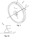
- Figs. 1 and 1A illustrate views of a hybrid disk.
- Fig. 1 shows a perspective view of hybrid disk 10
- Fig. 1A shows a radial cross-section of hybrid disk 10.
- Hybrid disk 10 includes bore region 12, rim region 14 and web region 16. During operation, hybrid disk 10 rotates about axis of rotation (centerline axis) 18. Bore region 12 is located radially inward of rim region 14 and web region 16 and rim region 14 is located radially outward of bore region 12 and web region 16.
- Bore region 12 is generally the central hub of hybrid disk 10 and can contain a through-hole for mounting hybrid disk 10 to a shaft.
- Web region 16 connects bore region 12 and rim region 14 so as to form a monolithic or one-piece hybrid rotor disk.
- the radially outer surface of hybrid disk 10 is located at rim region 14.
- Blade airfoils (not shown) are connected to hybrid disk 10 at the outer surface of rim region 14.
- hybrid disk 10 can have its greatest axial thickness (viewed left-to-right) at bore region 12. The region of least axial thickness can be at rim region 14 or a portion of web region 16 near rim region 14.
- hybrid disk 10 is formed from two substrates having differing material compositions and/or grain structures.
- the two substrates are forged or cast alloys.
- the two substrates are joined together to form hybrid disk 10 by inertia welding.
- the inertia welding process produces a solid-state joint between the two substrates via a metallurgical bond formed by a process where frictional heat is generated between a rotating substrate and a stationary substrate under an applied load. This bonding process minimizes solidification discontinuities and is essentially "self-cleaning" by removing any surface contaminants as the frayed metal flows out of the joint at the weld interface.
- the joint is located in a lower stress region of hybrid disk 10, for example, in web region 16.
- Rim substrate 22 is shaped (by forging, casting and/or machining) to approximate the finished shape of rim region 14 of hybrid disk 10. Rim substrate 22 is machined to have interface surface 25 where the metallurgical bond will be formed. Rim substrate 22 contains materials generally optimized for rim region 16 of hybrid disk 10. In some embodiments, rim substrate 22 contains cast, wrought and/or powder metallurgy alloys having high degrees of resistance to creep, rupture and cracking. Examples of suitable alloys for rim substrate 22 include PRM48, ME16, IN100, Alloy 10 and LSHR powder metallurgy alloys. In some examples, rim substrate 22 can include less than 0.06% carbon.
- Fig. 3 illustrates the metallurgical bond between bore substrate 20 and rim substrate 22 following inertia welding.
- inertia welding either the bore substrate 20 or the rim substrate 22 is held stationary while the other substrate is rotated about rotational axis 18.
- both bore substrate 20 and rim substrate 22 are oriented perpendicular to the rotational axis 18. While rotation is occurring, bore substrate 20 and rim substrate 22 are brought into contact with each other at respective interface surfaces 24 and 25. While rotation continues, interface surfaces 24 and 25 generate frictional heat that increases as pressure is applied in the direction of rotational axis 18.
- interface surfaces 24 and 25 of bore substrate 20 and rim substrate 22, respectively, where solid-state joint 26 is formed are angled relative to axis of rotation 18 (shown in Fig. 3 by angle ⁇ ). As shown, angle ⁇ is about 45°.
- the bond length (and resulting bond strength) of joint 26 is increased.
- the bonding surfaces of bore substrate 20 and rim substrate 22 are angled between 5° and 85° relative to axis of rotation 18. In further embodiments, the bonding surfaces of bore substrate 20 and rim substrate 22 are angled between 15° and 75° relative to axis of rotation 18.
- the bonding surfaces of bore substrate 20 and rim substrate 22 are angled between 30° and 60° relative to axis of rotation 18.
- Thermal and stress analyses of hybrid disk 10 can be performed to determine optimal angles of the bonding surfaces (interface surfaces 24 and 25, respectively) of bore substrate 20 and rim substrate 22.
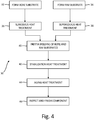
- Fig. 4 schematically illustrates one embodiment of method 30 for preparing hybrid disk 10.
- steps 32 and 34 of method 30 bore substrate 20 and rim substrate 22 are formed, respectively.
- steps 32 and 34 are followed by subsolvus heating treatment step 36 on bore substrate 20 and supersolvus heating treatment step 38 on rim substrate 22.
- step 40 bore substrate 20 and rim substrate 22 undergo inertia welding as described herein, resulting in the formation of solid-state joint 26 between bore substrate 20 and rim substrate 22.
- the welded bore substrate 20 and rim substrate 22 undergoes a stabilization heat treatment to relieve residual stress.
- step 44 the welded bore substrate 20 and rim substrate 22 undergoes an aging heat treatment to improve the component's material properties.
- step 46 the joined part is inspected and is then finish machined to form hybrid disk 10. Variations on the method illustrated in Fig. 4 are described above.
- Hybrid disk 10 prepared according to the method illustrated in Fig. 4 can include bore portion 12 having an average grain size between ASTM 11 and ASTM 9, rim portion 14 having an average grain size between ASTM 8 and ASTM 6, and web portion 16 located between bore portion 12 and rim portion 14.
- Web portion 16 includes solid-state joint 26 formed at interface surfaces 24 and 25 of bore substrate 20 and rim substrate 22, respectively. Solid-state joint 26 is angled between 5 degrees and 85 degrees relative to axis of rotation 18 of hybrid disk 10.
- a method of forming a hybrid component having an axis of rotation can include forming a first substrate comprising a first interface surface, the first substrate having a first average grain size; forming a second substrate comprising a second interface surface, the second substrate having a second average grain size different from the first average grain size; and inertia welding the first and second substrates together at a junction of the first and second interface surfaces to form a solid-state joint between the first and second substrates.
- the method of the preceding paragraph can optionally include, additionally and/or alternatively, any one or more of the following features, configurations and/or additional components:
- the joint can be angled between 5 degrees and 85 degrees relative to the axis of rotation of the hybrid component.
- Forming the first substrate can include heat treating the first substrate and machining the first interface surface.
- Forming the second substrate can include heat treating the second substrate and machining the second interface surface.
- the joint can be located between 50 percent and 80 percent of a radial distance from the axis of rotation of the hybrid disk to a radially outer edge of the rim substrate.
- the method can further include performing post-welding heat treatments on the hybrid disk and finish machining the hybrid disk.
- Forming the bore substrate can include heat treating the bore substrate and machining the first interface surface.
- Forming the rim substrate can include heat treating the rim substrate and machining the second interface surface.
- a hybrid disk can include a bore portion having an average grain size between ASTM 11 and ASTM 9; a rim portion having an average grain size between ASTM 8 and ASTM 6; and a web portion located between the bore portion and the rim portion, the web portion comprising a solid-state joint formed adjacent to a radially outer surface of the bore portion and a radially inner surface of the rim portion where the solid-state joint is angled between 5 degrees and 85 degrees relative to an axis of rotation of the hybrid disk.
Landscapes
- Chemical & Material Sciences (AREA)
- Engineering & Computer Science (AREA)
- Mechanical Engineering (AREA)
- Physics & Mathematics (AREA)
- Thermal Sciences (AREA)
- Crystallography & Structural Chemistry (AREA)
- Materials Engineering (AREA)
- Metallurgy (AREA)
- Organic Chemistry (AREA)
- General Engineering & Computer Science (AREA)
- Pressure Welding/Diffusion-Bonding (AREA)
- Turbine Rotor Nozzle Sealing (AREA)
Applications Claiming Priority (1)
| Application Number | Priority Date | Filing Date | Title |
|---|---|---|---|
| US15/292,753 US20180105914A1 (en) | 2016-10-13 | 2016-10-13 | Hybrid component and method of making |
Publications (1)
| Publication Number | Publication Date |
|---|---|
| EP3309264A1 true EP3309264A1 (de) | 2018-04-18 |
Family
ID=59677004
Family Applications (1)
| Application Number | Title | Priority Date | Filing Date |
|---|---|---|---|
| EP17185404.5A Withdrawn EP3309264A1 (de) | 2016-10-13 | 2017-08-08 | Hybridkomponente und verfahren zur herstellung |
Country Status (3)
| Country | Link |
|---|---|
| US (1) | US20180105914A1 (de) |
| EP (1) | EP3309264A1 (de) |
| JP (1) | JP2018062934A (de) |
Cited By (1)
| Publication number | Priority date | Publication date | Assignee | Title |
|---|---|---|---|---|
| EP3421622A1 (de) * | 2017-06-26 | 2019-01-02 | United Technologies Corporation | Festkörperschweissen von grobkörnigen pulvermetallurgischen superlegierungen auf nickelbasis |
Families Citing this family (3)
| Publication number | Priority date | Publication date | Assignee | Title |
|---|---|---|---|---|
| US10309232B2 (en) * | 2012-02-29 | 2019-06-04 | United Technologies Corporation | Gas turbine engine with stage dependent material selection for blades and disk |
| US20180371924A1 (en) * | 2017-06-27 | 2018-12-27 | Florida Turbine Technologies, Inc. | Additively Manufactured Blisk with Optimized Microstructure for Small Turbine Engines |
| US11549374B2 (en) * | 2020-02-18 | 2023-01-10 | Raytheon Technologies Corporation | Gas turbine rotor component and method of manufacture |
Citations (5)
| Publication number | Priority date | Publication date | Assignee | Title |
|---|---|---|---|---|
| EP1526252A2 (de) * | 2003-10-21 | 2005-04-27 | General Electric Company | Turbinenrotor mit dreifachen Eigenschaften und dessen Herstellungsweise |
| EP2353750A1 (de) * | 2010-02-05 | 2011-08-10 | General Electric Company | Schweiß- und Schmiedverfahren und damit hergestellte Komponente |
| EP2359975A1 (de) * | 2010-02-19 | 2011-08-24 | General Electric Company | Schweißverfahren und damit geformte Komponente |
| EP2520395A2 (de) * | 2011-05-04 | 2012-11-07 | General Electric Company | Komponenten und Verfahren zur Herstellung von Komponenten mit Regionen mit unterschiedlicher Kornstruktur |
| EP2530181A1 (de) * | 2011-06-03 | 2012-12-05 | General Electric Company | Komponenten und Verfahren zur Herstellung von Komponenten mit Regionen mit unterschiedlicher Kornstruktur |
-
2016
- 2016-10-13 US US15/292,753 patent/US20180105914A1/en not_active Abandoned
-
2017
- 2017-08-08 EP EP17185404.5A patent/EP3309264A1/de not_active Withdrawn
- 2017-08-10 JP JP2017155676A patent/JP2018062934A/ja active Pending
Patent Citations (5)
| Publication number | Priority date | Publication date | Assignee | Title |
|---|---|---|---|---|
| EP1526252A2 (de) * | 2003-10-21 | 2005-04-27 | General Electric Company | Turbinenrotor mit dreifachen Eigenschaften und dessen Herstellungsweise |
| EP2353750A1 (de) * | 2010-02-05 | 2011-08-10 | General Electric Company | Schweiß- und Schmiedverfahren und damit hergestellte Komponente |
| EP2359975A1 (de) * | 2010-02-19 | 2011-08-24 | General Electric Company | Schweißverfahren und damit geformte Komponente |
| EP2520395A2 (de) * | 2011-05-04 | 2012-11-07 | General Electric Company | Komponenten und Verfahren zur Herstellung von Komponenten mit Regionen mit unterschiedlicher Kornstruktur |
| EP2530181A1 (de) * | 2011-06-03 | 2012-12-05 | General Electric Company | Komponenten und Verfahren zur Herstellung von Komponenten mit Regionen mit unterschiedlicher Kornstruktur |
Cited By (3)
| Publication number | Priority date | Publication date | Assignee | Title |
|---|---|---|---|---|
| EP3421622A1 (de) * | 2017-06-26 | 2019-01-02 | United Technologies Corporation | Festkörperschweissen von grobkörnigen pulvermetallurgischen superlegierungen auf nickelbasis |
| US10718041B2 (en) | 2017-06-26 | 2020-07-21 | Raytheon Technologies Corporation | Solid-state welding of coarse grain powder metallurgy nickel-based superalloys |
| EP3995594A1 (de) * | 2017-06-26 | 2022-05-11 | Raytheon Technologies Corporation | Festkörperschweissen von grobkörnigen pulvermetallurgischen superlegierungen auf nickelbasis |
Also Published As
| Publication number | Publication date |
|---|---|
| US20180105914A1 (en) | 2018-04-19 |
| JP2018062934A (ja) | 2018-04-19 |
Similar Documents
| Publication | Publication Date | Title |
|---|---|---|
| US8636195B2 (en) | Welding process and component formed thereby | |
| EP3421622B1 (de) | Festkörperschweissen von grobkörnigen pulvermetallurgischen superlegierungen auf nickelbasis | |
| US8146795B2 (en) | Method of friction welding | |
| CN101191423B (zh) | 旋转组装部件及制造这种部件的方法 | |
| US8480368B2 (en) | Welding process and component produced therefrom | |
| US20180209280A1 (en) | Bladed disc and method of manufacturing the same | |
| JP2011501019A (ja) | ブリスクまたはブリングの製造方法、該製造方法により製造された構成部品、及びタービンブレード | |
| CN108343475B (zh) | 叶片盘及制造叶片盘的方法 | |
| US7841506B2 (en) | Method of manufacture of dual titanium alloy impeller | |
| EP3309264A1 (de) | Hybridkomponente und verfahren zur herstellung | |
| EP3308900A1 (de) | Hybridkomponente und verfahren zur herstellung | |
| US7370787B2 (en) | Compressor rotor and method for making | |
| US8187724B2 (en) | Method of manufacture of a dual alloy impeller | |
| CN102852559B (zh) | 涡轮盘预制件、其制成的焊接涡轮转子及制造它们的方法 | |
| US20190184489A1 (en) | Method for joining components and device | |
| EP3725457B1 (de) | Turbinengehäusekomponente und reparaturverfahren dafür | |
| US20110142653A1 (en) | Two piece impeller | |
| US20190376396A1 (en) | Turbine blisk and process of making | |
| US20080000558A1 (en) | Friction welding |
Legal Events
| Date | Code | Title | Description |
|---|---|---|---|
| PUAI | Public reference made under article 153(3) epc to a published international application that has entered the european phase |
Free format text: ORIGINAL CODE: 0009012 |
|
| STAA | Information on the status of an ep patent application or granted ep patent |
Free format text: STATUS: THE APPLICATION HAS BEEN PUBLISHED |
|
| AK | Designated contracting states |
Kind code of ref document: A1 Designated state(s): AL AT BE BG CH CY CZ DE DK EE ES FI FR GB GR HR HU IE IS IT LI LT LU LV MC MK MT NL NO PL PT RO RS SE SI SK SM TR |
|
| AX | Request for extension of the european patent |
Extension state: BA ME |
|
| STAA | Information on the status of an ep patent application or granted ep patent |
Free format text: STATUS: THE APPLICATION IS DEEMED TO BE WITHDRAWN |
|
| 18D | Application deemed to be withdrawn |
Effective date: 20181019 |