EP3309338B1 - Beschlag für schiebetür, schiebetür und herstellunsverfahren hierfür - Google Patents
Beschlag für schiebetür, schiebetür und herstellunsverfahren hierfür Download PDFInfo
- Publication number
- EP3309338B1 EP3309338B1 EP17193208.0A EP17193208A EP3309338B1 EP 3309338 B1 EP3309338 B1 EP 3309338B1 EP 17193208 A EP17193208 A EP 17193208A EP 3309338 B1 EP3309338 B1 EP 3309338B1
- Authority
- EP
- European Patent Office
- Prior art keywords
- guide
- door
- support
- component
- sliding
- Prior art date
- Legal status (The legal status is an assumption and is not a legal conclusion. Google has not performed a legal analysis and makes no representation as to the accuracy of the status listed.)
- Active
Links
Images






Classifications
-
- E—FIXED CONSTRUCTIONS
- E05—LOCKS; KEYS; WINDOW OR DOOR FITTINGS; SAFES
- E05D—HINGES OR SUSPENSION DEVICES FOR DOORS, WINDOWS OR WINGS
- E05D15/00—Suspension arrangements for wings
- E05D15/06—Suspension arrangements for wings for wings sliding horizontally more or less in their own plane
- E05D15/0621—Details, e.g. suspension or supporting guides
-
- E—FIXED CONSTRUCTIONS
- E05—LOCKS; KEYS; WINDOW OR DOOR FITTINGS; SAFES
- E05D—HINGES OR SUSPENSION DEVICES FOR DOORS, WINDOWS OR WINGS
- E05D15/00—Suspension arrangements for wings
- E05D15/06—Suspension arrangements for wings for wings sliding horizontally more or less in their own plane
- E05D15/0621—Details, e.g. suspension or supporting guides
- E05D15/0626—Details, e.g. suspension or supporting guides for wings suspended at the top
-
- E—FIXED CONSTRUCTIONS
- E05—LOCKS; KEYS; WINDOW OR DOOR FITTINGS; SAFES
- E05D—HINGES OR SUSPENSION DEVICES FOR DOORS, WINDOWS OR WINGS
- E05D15/00—Suspension arrangements for wings
- E05D15/06—Suspension arrangements for wings for wings sliding horizontally more or less in their own plane
- E05D15/0621—Details, e.g. suspension or supporting guides
- E05D15/0626—Details, e.g. suspension or supporting guides for wings suspended at the top
- E05D15/0656—Bottom guides
-
- E—FIXED CONSTRUCTIONS
- E05—LOCKS; KEYS; WINDOW OR DOOR FITTINGS; SAFES
- E05Y—INDEXING SCHEME ASSOCIATED WITH SUBCLASSES E05D AND E05F, RELATING TO CONSTRUCTION ELEMENTS, ELECTRIC CONTROL, POWER SUPPLY, POWER SIGNAL OR TRANSMISSION, USER INTERFACES, MOUNTING OR COUPLING, DETAILS, ACCESSORIES, AUXILIARY OPERATIONS NOT OTHERWISE PROVIDED FOR, APPLICATION THEREOF
- E05Y2201/00—Constructional elements; Accessories therefor
- E05Y2201/60—Suspension or transmission members; Accessories therefor
- E05Y2201/606—Accessories therefor
- E05Y2201/61—Cooperation between suspension or transmission members
- E05Y2201/612—Cooperation between suspension or transmission members between carriers and rails
- E05Y2201/614—Anti-derailing means
-
- E—FIXED CONSTRUCTIONS
- E05—LOCKS; KEYS; WINDOW OR DOOR FITTINGS; SAFES
- E05Y—INDEXING SCHEME ASSOCIATED WITH SUBCLASSES E05D AND E05F, RELATING TO CONSTRUCTION ELEMENTS, ELECTRIC CONTROL, POWER SUPPLY, POWER SIGNAL OR TRANSMISSION, USER INTERFACES, MOUNTING OR COUPLING, DETAILS, ACCESSORIES, AUXILIARY OPERATIONS NOT OTHERWISE PROVIDED FOR, APPLICATION THEREOF
- E05Y2900/00—Application of doors, windows, wings or fittings thereof
- E05Y2900/10—Application of doors, windows, wings or fittings thereof for buildings or parts thereof
Definitions
- Present invention relates, in general, to a sliding door in which a door is adapted to assume any position between extreme opening and closing positions of a door opening in a wall.
- the present invention relates to a sliding door comprising a device fixed to the wall and arranged to guide and support by way of idle wheels the door in its sliding between the extreme positions.
- Sliding doors are known in which a door is made to run on a device fixed to a vertical wall.
- patent document WO2012073215_A discloses a sliding door comprising both means for guiding and supporting the door, fixed to a vertical wall, and sliding means secured to lower ends of the door.
- the known guide and support means comprises idle rotating organs fixed to the vertical wall.
- Each known sliding means comprises a wheel respectively located at one of the lower ends of the door, and is suitable to slide freely so as to allow the sliding of the door on the floor.
- a first problem with the sliding doors of the known type is that, since the door is suspended on idle wheels fixed to a vertical wall, a real risk exists that the door may disengage from the idle wheels if, in use, the door is run with violence between the extreme positions.
- a second problem of the sliding doors of known type, associated to the first one, is that any doorstop fixed to the door can contribute to facilitate the release of the door from the idle wheels if, in use, the door bangs with violence against end limits.
- a third problem of the sliding doors of known type, associated to the first two, is that known sliding means provided at the lower ends of the door can be extremely sensitive to any irregularity on the floor and can therefore contribute once again to facilitate the release of the door from the idle wheels.
- the object of the present invention is thus to solve the problems outlined above of the known art.
- the present invention also relates to a method for manufacturing a sliding door.
- the sliding door comprises a door arranged to slide, in use, between extreme positions of a door opening of a vertical wall, a top profile fixed to the door and a support device arranged to guide and support the door, and comprising a frame element fixable to a vertical wall, a support guide arranged to be moved and adjusted in vertical direction with respect to the frame element, a guide and support component fixed to the support guide and comprising at least one idle wheel arranged to guide and support, in use, the top profile, said guide and support component being arranged to be moved and adjusted in vertical direction as to said frame element by way of an adjustment element, an anti-releasing component fastened to the support guide, said anti-releasing component, comprising a lever and being arranged to be moved and adjusted in vertical direction as to the frame element by way of said adjustment element, whereby by moving and adjusting in vertical direction said guide and support component it is provided that said at least one idle wheel of said guide and support component is brought into contact with said top profile and said anti-releasing component is automatically brought into engagement with said top profile by
- the support device further comprises a pivotable component associated to the guide and support component and configured to handle and lock on a horizontal surface the at least one idle wheel with a certain angle as regards the vertical wall.
- the sliding door further comprises a sliding device comprising at least one carriage for sliding on a horizontal plane or on the floor and comprising a first and a second idle wheels adjacent each other and covered by way of polyurethane covers.
- a sliding door 10 comprises a door 11 which is adapted to freely move within extreme positions so as to open and close a door opening 12 such as a real or dummy door opening, a support device (guide and/or support device) 14 comprising a frame element 19 fixed to a vertical wall 15, laterally to a lateral edge 15a and above a top edge 15b of the door opening 12, and at least one sliding device 17 comprising, for example, a pair of carriages, 17a and 17b, which slide on a horizontal plane, for example on a floor, and are fixed to a lower surface 74 of the door 11, preferably at opposite ends of such door 11.
- a support device guide and/or support device 14 comprising a frame element 19 fixed to a vertical wall 15, laterally to a lateral edge 15a and above a top edge 15b of the door opening 12
- at least one sliding device 17 comprising, for example, a pair of carriages, 17a and 17b, which slide on a horizontal plane, for example on a floor, and are fixed to
- the sliding door 10 further comprises shock absorbing devices 18a and 18b ( Fig. 1 , Figs. 5a-5b ) of a predetermined width "L" and fixed to the door 11 in an upper door area and arranged to damp, in use, the door when reaching its end limits.
- the door 11 also comprises a top profile 21 configured to cooperate with the support device 14 and preferably secured to a milling 84 made on one side 86 of two main sides of the door 11 in a distal position from the lower surface 74 of the door 11, and an alignment part 23, for example a milling made on the lower surface 74 of the door.
- the top profile 21 is directly secured to one side 86 of the door 11.
- the top profile 21 is provided to allow the door 11 to slide on the support device 14 and, for example, the alignment part 23 is provided for cooperating with a guide component 22 fixed to the horizontal plane or floor, so as to keep the door 11 parallel to the vertical wall 15.
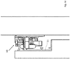
- the support device 14 comprises a support guide 42, arranged to be moved and adjusted in vertical direction with respect to the frame element 19, and a guide and support component 40 ( Fig. 1 , Fig. 2 , Figures 3a-3c ) preferably comprising at least one first and one second idle wheel, 401 and 402, placed with a rotation axis orthogonal or substantially orthogonal to the surface of the vertical wall and spaced apart at a predetermined distance, for example comprised between 100 and 200 mm.
- the guide and support component 40 may comprise a single idle wheel, 401 or 402, without thereby departing from the scope of what is disclosed and claimed.
- the guide and support component 40 comprises a third and/or fourth idle wheel, 403 and 404, preferably arranged adjacent but distal and opposite to the first and/or to the second idle wheel, 401 and 402, respectively, and oriented with a rotation axis parallel to the surface of the vertical wall 15.
- the guide and support component 40 in particular its first and second idle wheels, 401 and 402, are arranged to guide and support the door 11 and to slide along the top profile 21 over an upper inner surface 25 of the top profile 21.
- the third and fourth idle wheels, 403 and 404 are configured to lean on a lateral surface of the profile 21 and preferably are arranged to provide an additional guide and/or a clearance reducer between the top profile 21 and the support device 14.
- the guide and support component 40 is configured so that it can be adjusted in a vertical direction and locked by way of an adjustment element 41, for example a regulation screw, so as to enable, in use, first and second idle wheels, 401 and 402, to arrive in contact to the upper inner surface 25 of the top profile 21.
- an adjustment element 41 for example a regulation screw
- the guide and support component 40 is fixed to the support guide 42 and is operable so as to be moved and adjusted in vertical direction, by way of the adjustment element 41, with respect to the frame element 19 fixable to the vertical wall 15 and to be brought into contact with the upper inner surface 25 of the top profile 21.
- the adjustment element 41 by moving the at least one idle wheel 401 or 402 or the first and second idle wheels, 401 and 402, aligned each other in a predetermined manner, is configured so as to allow the guide and support component 40 to be brought into contact with the upper inner surface 25 of the top profile 21, while at the same time providing a predetermined alignment of the door 11 with respect to the wall 15.
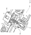
- the support device 14 comprises an anti-releasing component 50 fastened to the support guide 42 of the guide and support component 40 and configured to allow, in use, an automatic secure attachment of the door 11 to the first device 14.
- the anti-releasing component (clamping or anti-jamming component) 50 preferably associated to the guide and support component 40, comprises a shell 52 and a lever 51, such as a snap lever resiliently loaded by a resilient element 54, for example a helical spring.
- the lever 51 comprises first and second ends, 55a and 55b respectively, configured to removably engage, alternatively, externally or internally, the shell 52 and a sealing end 56 configured to engage and mechanically hold a contour 27a, for instance a "L" contour, made on an upper external surface 26 of the top profile 21.
- the lever 51 when in a rest position, is retained within the shell 52 by way of the first ends 55a which are held hooked to a first corresponding protruding element 57a, comprised within to the shell 52.
- the lever 51 is released by the corresponding protruding element 57a and the second ends 55b, for example one or more protruding elements pushed by the spring 54, hook second corresponding protruding elements 57b comprised within the shell 52.
- the lever 51 protruding from shell 52 is arranged to contact an outer contour 27b of the top profile 21 until the first and second idle wheels, 401 and 402, are brought into contact with the upper inner surface 25 of the top profile 21 and, for example, at the same time, the sealing end 56 of the lever 51, pushed by the spring 54, goes off the outer contour 27b of the top profile 21 with a click, for example an audible sounding click, such to grant, to whom is installing the sliding door 10, that the lever 51 is brought into engagement with the contour 27a, i.e. with the top profile 21, and, consequently, the door 11 is properly installed and secured.
- a click for example an audible sounding click
- the presence of the lever 51 within the contour 27a shaped by the upper external surface 26 of the top profile 21 prevents that the door 11 goes out of the support device 14, for instance, subsequent to any jerk of the door causing the first and/or the second idle wheels, 401 and 402, to move away from the upper inner surface 25 of top profile 21.
- the lever 51 is made of a plastic material, such as NYLON, so as to allow, in use, an easy hooking to and release from the shell 52.
- the structure of the anti-releasing component 50 or similar structures, being linked to the positioning, in use, of the guide and support component 40, allow to hook the door 11 and, at the same time, to automatically secure it, by acting on an adjustment element 41 common to the guide and support component 40 and to the anti-releasing component 50.
- the adjustment element 41 ensures that the guide and support component 40 is brought into contact with the top profile 21 and that, at the same time, the anti-releasing component 50 is automatically located so as to secure the top profile 21 and, consequently, the door 11.
- the support device 14 comprises a pivotable component 60 ( Fig. 1 , Fig. 2 , Fig. 3a-3c , Fig. 4 ), fixed to the support guide 42 of the guide and support component 40, and configured to allow, in use, to solve any parallelism problem in a predetermined range, for example within a range of ⁇ 2°, between the sliding door 10 and the vertical wall 15.
- the pivotable component (parallelism adjustment or tilting component) 60 is associated to the guide and support component 40 and is configured to allow the door 11 to slide parallel to the wall 15 even when the vertical wall to which the support device 14 is attached is not perfectly aligned with the door opening 12 but has a certain inclination or curvature.
- the pivotable component 60 comprises first and second movement and locking elements, 61 and 62, for example respective screws adapted to be fastened to the support guide 42 and operating within a first and a second slot, 63 and 64, disposed on a horizontal surface of the support guide 42 and arranged to move the pivotable component 60 with respect to the frame element 19.
- the movement of the first movement and locking element 61 in a certain direction on the horizontal surface involves the movement of the second movement and locking element 62 in an opposite direction so as to maintain aligned the first and second idle wheels 401 and 402.
- the movement of the first movement and locking element 61 is independent of the movement of the second movement and locking element 62.
- Such an embodiment may be convenient in case of arc-shaped doors.
- the first idle wheel 401 and, if present, the third idle wheel 403 are arranged to be moved and locked on a horizontal plane in a predetermined angular range with respect to the second idle wheel 402 and, if present, to the fourth idle wheel 404, by way of the first and second movement and locking elements, 61 and 62, respectively.
- the first movement and locking element 61 or, alternately, the second movement and locking element 62 may not be present or only one movement and locking element, 61 or 62, may be present for controlling the tilting, for example in opposite directions, of both the wheels 401 and 402 with respect to the frame element 19 and therefore with respect to the vertical wall 15.
- the pivotable component 60 allows to move and lock by way of at least one movement and locking element, 61 or 62, on the horizontal plane at least the first and/or the second idle wheel, 401 or 402, of the guide and support component 40.
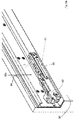
- the shock absorbing devices, 18a and 18b, ( Fig. 1 , Figs. 5a-5b ) are provided, in accordance with one of the various embodiments, in the top area of the door 11, preferably at opposite ends of the top profile 21, and are arranged to absorb and block the movement of the door at the extreme opening and closing positions of the door opening 12.
- the shock absorbing devices, 18a and 18b are identical to each other and are located in a specular position with respect to a plane orthogonal to the top profile 21.
- one of the two shock absorbing devices is disclosed, in particular the shock absorbing device 18a, and the numerical references are identical for both shock absorbing devices 18a and 18b.
- the shock absorbing devices may not be identical to each other.
- the shock absorbing device 18a comprises shock absorbers (dampers) 83 of known type, for instance a spring associated to a shock absorber, and a locking element 85 of known type that are arranged to absorb and block the sliding of the door 11 with respect to the support device 14 at the extreme positions.
- shock absorbers for instance a spring associated to a shock absorber
- locking element 85 of known type that are arranged to absorb and block the sliding of the door 11 with respect to the support device 14 at the extreme positions.
- the shock absorbing device 18a further comprises an idle wheel 82 with a diameter larger than the predetermined width "L" of the shock absorbing device and with a rotation axis parallel to the vertical wall 15.
- the idle wheel 82 is fixed to the shock absorbing device and positioned, in use, at or near the end of the top profile 21.
- the idle wheel 82 is shaped so as to protrude few millimeters, for example 5-30 mm, from the side 86 of the door 11.
- the idle wheel 82 protrudes few millimeters, for example 5-20 mm, from the shock absorbing device.
- the idle wheel 82 is arranged to operate as a wall-saver in case of oscillations of the door when sliding between the extreme opening and closing positions of the door opening 12.
- the carriages 17a or 17b ( Fig. 1 , Fig. 6 ) comprised in the sliding device 17 are, for example, fixed to the opposite ends of the door 11 on a lower surface 74 thereof, and, according to the preferred embodiment, respectively comprise, one or more shells (wheel shells) 71, such as a shell each, and at least a first 72a and second idle wheel 72b, comprised within each carriage, 17a or 17b, and down protruding by a predetermined distance, for example 5-10 mm, from the shells 71.
- carriages 17a and 17b are two identical carriages, so that same numerical references are used in the following description for each carriage.
- carriages may not be identical to each other as well as the carriages may be one or more than two, depending on various constructive requirements of the sliding door 10.
- the shells 71 comprised in each carriage, 17a or 17b are inserted into respective housings 75 formed on the lower surface 74 of the door 11, at opposite ends of the same door 11, and are secured thereto in a known manner, for example by self-tapping screws.
- a pair of idle wheels, 72a and 72b is secured, but according to other embodiments it is provided that a single wheel is secured to each shell with the constraint that carriages, 17a or 17b, comprise at least a first and a second idle wheel adjacent to each other, 72a and 72b.
- the sliding device 17 comprising at least two carriages 17a and 17b and at least two wheels 72a and 72b for each carriage has a lot of advantages over sliding devices or carriages known in the art.
- the sliding device 17 does not require elastically deformable springs or levers, and thanks to the configurations described it is also capable of reducing or even eliminating jerking of the door 11 when it slides between the extreme opening and closing positions of the door opening 12, in particular, next to possible spaces between tiles or to floor irregularities.
- the idle wheels 72a and 72b may also be different from each other as regards, for example, the bearings 73a and 73b, the thickness "SP" and/or the width "LP" of the respective coatings, 76a and 76b, without thereby departing from the scope of what is disclosed and claimed.
- Manufacturing and assembly of the sliding door 10 described herein comprises some manufacturing steps, prior to the assembly, and some real assembly steps.
- the manufacturing steps or assembly preparation steps comprise the following steps even in a different sequence or grouped together:
- the sliding door as disclosed comprising one or more of the disclosed devices and components, has one or more of the following advantages over known art:
Landscapes
- Engineering & Computer Science (AREA)
- Mechanical Engineering (AREA)
- Wing Frames And Configurations (AREA)
- Support Devices For Sliding Doors (AREA)
- Door And Window Frames Mounted To Openings (AREA)
- Refrigerator Housings (AREA)
Claims (13)
- Schiebetür, umfassend:- eine Tür (11), die angeordnet ist, um, bei Verwendung, zwischen Extrempositionen einer Türöffnung (12) einer vertikalen Wand (15) zu gleiten,- ein oberes Profil (21), das an der Tür (11) der Schiebetür (10) befestigbar ist, und- eine Tragvorrichtung (14), die angeordnet ist, um die Tür (11) zu führen und zu tragen, und umfassend- ein Rahmenelement (19), das an einer vertikalen Wand (15) befestigbar ist, dadurch gekennzeichnet, dass die Tragvorrichtung (14) ferner umfasst- eine Tragführung (42), die angeordnet ist, um in Bezug auf das Rahmenelement (19) in vertikaler Richtung bewegt und verstellt zu werden,- eine Führungs- und Tragkomponente (40), die an der Tragführung (42) befestigt ist und mindestens ein Leitrad (401, 402) umfasst, das angeordnet ist, um bei Verwendung das obere Profil (21) zu führen und zu tragen, wobei die Führungs- und Tragkomponente (40) angeordnet ist, um hinsichtlich des Rahmenelements (19) mittels eines Verstellelements (41) in vertikaler Richtung bewegt und verstellt zu werden,- eine an der Tragführung (42) befestigte Lockerungssicherungskomponente (50), wobei die Lockerungssicherungskomponente (50) einen Hebel (51) umfasst und angeordnet ist, um hinsichtlich des Rahmenelements (19) mittels des Verstellelements (41) in vertikaler Richtung bewegt und verstellt zu werden, wobei durch Bewegen und Verstellen der Führungs- und Tragkomponente (40) in vertikaler Richtung dafür gesorgt wird, dass das mindestens eine Leitrad (401, 402) der Führungs- und Tragkomponente (40) mit dem oberen Profil (21) in Kontakt gebracht wird und die Lockerungssicherungskomponente (50) mittels des Hebels (51) automatisch mit dem oberen Profil (21) in Eingriff gebracht wird.
- Schiebetür nach Anspruch 1, wobei- der Hebel (51) durch ein elastisches Element (54) elastisch belastet wird und umfasst- ein Abdichtungsende (56), und wobei- das obere Profil (21) auf einer oberen Außenfläche (26) umfasst,- eine Außenkontur (27a), die angeordnet ist, um bei Verwendung mit dem Abdichtungsende (56) zusammenzuwirken, um so zu vermeiden, dass das obere Profil (21) aus der Tragvorrichtung (14) heraustritt.
- Schiebetür nach einem der Ansprüche 1 bis 2, wobei die Führungs- und Tragkomponente (40) ein erstes (401) und ein zweites Leitrad (402) umfasst, die angeordnet sind, um die Tür (11) mittels des oberen Profils (21) zu führen und zu tragen.
- Schiebetür nach Anspruch 3, ferner umfassend- eine schwenkbare Komponente (60), die angeordnet ist, um mit der Führungs- und Tragkomponente (40) zusammenzuwirken, und umfassend- ein Bewegungs- und Verriegelungselement (61, 62), das angeordnet ist, um sich auf einer horizontalen Fläche zu bewegen und mit einem bestimmten Winkel das erste Leitrad (401) und das zweite Leitrad (402) in umgekehrten Richtungen hinsichtlich des Rahmenelements (19) zu verriegeln.
- Schiebetür nach einem der Ansprüche 1 bis 2, ferner umfassend- eine schwenkbare Komponente (60), die angeordnet ist, um mit der Führungs- und Tragkomponente (40) zusammenzuwirken, und umfassend- mindestens ein Bewegungs- und Verriegelungselement (61, 62), das angeordnet ist, um das mindestens eine Leitrad (401, 402) auf einer horizontalen Fläche zu bewegen und das mindestens eine Leitrad (401, 402) mit einem bestimmten Winkel hinsichtlich des Rahmenelements (19) zu verriegeln.
- Schiebetür nach einem der Ansprüche 1 bis 5, wobei die Führungs- und Tragkomponente (40) ferner umfasst- zwei zusätzliche Leiträder (403, 404) umfassend eine Drehachse, die parallel zu einer vertikalen Wand (15) ist.
- Schiebetür nach einem der Ansprüche 1 bis 6, ferner umfassend- eine Gleitvorrichtung (17) umfassend mindestens einen Schlitten (17a, 17b), der an einer unteren Fläche der Tür befestigt und angeordnet ist, um auf einer horizontalen Ebene zu gleiten.
- Schiebetür nach Anspruch 7, wobei- der mindestens eine Schlitten (17a, 17b), der in der Gleitvorrichtung (17) beinhaltet ist, umfasst- ein erstes und ein zweites Leiträder (72a, 72b), die zueinander benachbart sind und jeweilige Lager (73a, 73b) umfassen, die mittels einer aus Polyurethan (76a, 76b) bestehenden Abdeckung abgedeckt sind.
- Schiebetür nach Anspruch 8, wobei die Abdeckung durch Gießen von Polyurethan hergestellt wird.
- Schiebetür nach einem der Ansprüche 1 bis 9, ferner umfassend, an mindestens einem Ende des Führungs- und Tragprofils (21) befestigt,- eine Stoßdämpfungsvorrichtung (18a, 18b), umfassend- Stoßdämpfer (83) und ein Verriegelungselement (85) mit vorbestimmter Breite (L) und Anordnung zum Absorbieren und Verriegeln des Gleitens der Tür (11) zwischen Extrempositionen einer Türöffnung (12), und- ein Leitrad (82) mit einem Durchmesser von mehr als der vorbestimmten Breite (L) und einer Achse, die parallel zu einer vertikalen Wand (15) ist, wobei das Leitrad so angeordnet ist, dass es bei Verwendung als Wandschutz im Falle von Oszillationen der Tür zwischen Extrempositionen der Öffnung (12) dient.
- Verfahren zur Herstellung einer Schiebetür (10), umfassend die folgenden Schritte:- Bereitstellen einer Tür (11),- Bereitstellen eines oberen Profils (21), das an der Tür (11) der Schiebetür (10) befestigt ist,- Bereitstellen einer Tragvorrichtung (14) umfassend- ein Rahmenelement (19), das an einer vertikalen Wand (15) befestigbar ist,- eine Tragführung (42), die angeordnet ist, um in Bezug auf das Rahmenelement (19) in vertikaler Richtung bewegt und verstellt zu werden,- eine Führungs- und Tragkomponente (40), die an der Tragführung (42) befestigt ist und mindestens ein Leitrad (401, 402) umfasst, das angeordnet ist, um bei Verwendung das obere Profil (21) zu führen und zu tragen, wobei die Führungs- und Tragkomponente (40) angeordnet ist, um hinsichtlich des Rahmenelements (19) mittels eines Verstellelements (41) in vertikaler Richtung bewegt und verstellt zu werden,- eine Lockerungssicherungskomponente (50) mit einem Hebel (51), wobei die Lockerungssicherungskomponente (50) angeordnet ist, um hinsichtlich des Rahmenelements (19) mittels eines Verstellelements (41) in vertikaler Richtung bewegt und verstellt zu werden,- Bewegen und Verstellen, in vertikaler Richtung, der Führungs- und Tragkomponente (40) und der Lockerungssicherungskomponente (50) hinsichtlich des Rahmenelements (19) mittels des Verstellelements (41), und- automatisches Inkontaktbringen des mindestens einen Leitrads (401, 402) der Führungs- und Tragkomponente (40) mit dem oberen Profil (21) und Ineingriffbringen der Lockerungssicherungskomponente (50) mit dem oberen Profil (21) mittels des Hebels (51).
- Verfahren nach Anspruch 11, umfassend die folgenden weiteren Schritte:- Bereitstellen einer Gleitvorrichtung (17) umfassend mindestens einen Schlitten (17a, 17b), der angeordnet ist, um auf einer horizontalen Ebene zu gleiten,- Befestigen der Gleitvorrichtung (17) an einer unteren Fläche (74) der Tür (11), so dass die Gleitvorrichtung (17) angeordnet ist, um auf einer horizontalen Ebene zu gleiten.
- Verfahren nach Anspruch 11 oder 12, umfassend die folgenden weiteren Schritte:- Bereitstellen einer Kippkomponente (60), die mit der Führungs- und Tragkomponente (40) assoziiert ist,- Bewegen, mittels eines Bewegungs- und Verriegelungselements (61, 62), des mindestens einen Leitrads (401, 402) auf einer horizontalen Fläche, und- Verriegeln des mindestens einen Leitrads (401, 402) in einer bestimmten Position auf einer horizontalen Fläche hinsichtlich des Rahmenelements (19).
Priority Applications (3)
| Application Number | Priority Date | Filing Date | Title |
|---|---|---|---|
| HRP20220062TT HRP20220062T1 (hr) | 2016-10-14 | 2017-09-26 | Uređaj za klizna vrata, klizna vrata i postupak njihove proizvodnje |
| PL17193208T PL3309338T3 (pl) | 2016-10-14 | 2017-09-26 | Urządzenie drzwi przesuwnych, drzwi przesuwne i sposób ich produkcji |
| SI201731049T SI3309338T1 (sl) | 2016-10-14 | 2017-09-26 | Naprava za drsna vrata, drsna vrata in način njihove izdelave |
Applications Claiming Priority (1)
| Application Number | Priority Date | Filing Date | Title |
|---|---|---|---|
| IT102016000103356A IT201600103356A1 (it) | 2016-10-14 | 2016-10-14 | Porta scorrevole, dispositivi compresi nella stessa e relativo metodo di realizzazione |
Publications (2)
| Publication Number | Publication Date |
|---|---|
| EP3309338A1 EP3309338A1 (de) | 2018-04-18 |
| EP3309338B1 true EP3309338B1 (de) | 2021-12-08 |
Family
ID=58159359
Family Applications (1)
| Application Number | Title | Priority Date | Filing Date |
|---|---|---|---|
| EP17193208.0A Active EP3309338B1 (de) | 2016-10-14 | 2017-09-26 | Beschlag für schiebetür, schiebetür und herstellunsverfahren hierfür |
Country Status (8)
| Country | Link |
|---|---|
| EP (1) | EP3309338B1 (de) |
| DK (1) | DK3309338T3 (de) |
| ES (1) | ES2902823T3 (de) |
| HR (1) | HRP20220062T1 (de) |
| HU (1) | HUE058939T2 (de) |
| IT (1) | IT201600103356A1 (de) |
| PL (1) | PL3309338T3 (de) |
| SI (1) | SI3309338T1 (de) |
Families Citing this family (1)
| Publication number | Priority date | Publication date | Assignee | Title |
|---|---|---|---|---|
| IT202300027576A1 (it) * | 2023-12-21 | 2025-06-21 | Alban Giacomo Spa | “carrello di scorrimento per un serramento ad anta scorrevole e serramento ad anta scorrevole” |
Family Cites Families (2)
| Publication number | Priority date | Publication date | Assignee | Title |
|---|---|---|---|---|
| DE202009005269U1 (de) * | 2009-09-10 | 2011-01-20 | Hettich-Heinze Gmbh & Co. Kg | Laufteil für einen Schiebetürflügel |
| IT1403194B1 (it) * | 2010-12-02 | 2013-10-15 | Ballotta | Porta scorrevole |
-
2016
- 2016-10-14 IT IT102016000103356A patent/IT201600103356A1/it unknown
-
2017
- 2017-09-26 DK DK17193208.0T patent/DK3309338T3/da active
- 2017-09-26 EP EP17193208.0A patent/EP3309338B1/de active Active
- 2017-09-26 PL PL17193208T patent/PL3309338T3/pl unknown
- 2017-09-26 HU HUE17193208A patent/HUE058939T2/hu unknown
- 2017-09-26 SI SI201731049T patent/SI3309338T1/sl unknown
- 2017-09-26 ES ES17193208T patent/ES2902823T3/es active Active
- 2017-09-26 HR HRP20220062TT patent/HRP20220062T1/hr unknown
Non-Patent Citations (1)
| Title |
|---|
| None * |
Also Published As
| Publication number | Publication date |
|---|---|
| IT201600103356A1 (it) | 2018-04-14 |
| SI3309338T1 (sl) | 2022-04-29 |
| HUE058939T2 (hu) | 2022-09-28 |
| EP3309338A1 (de) | 2018-04-18 |
| DK3309338T3 (da) | 2022-01-17 |
| ES2902823T3 (es) | 2022-03-30 |
| HRP20220062T1 (hr) | 2022-04-01 |
| PL3309338T3 (pl) | 2022-02-21 |
Similar Documents
| Publication | Publication Date | Title |
|---|---|---|
| US9303707B2 (en) | Roller shade system and method | |
| CA2779764C (en) | Adjustable roller shade bracket | |
| EP3309338B1 (de) | Beschlag für schiebetür, schiebetür und herstellunsverfahren hierfür | |
| AU2020334121A1 (en) | Device for supporting a frame in an opening, a frame with such a device, a window, a recreational vehicle with such a frame or window and method for supporting the frame or the window in the opening | |
| CZ301734B6 (cs) | Zarízení pro otocné a posuvné zavešení tabulí | |
| JP2014092026A (ja) | 吊設機器の振れ止め措置構造 | |
| US20130061427A1 (en) | Hinge and method of adjustment | |
| US20180028384A1 (en) | Quarter turn track bracket (QTTB) for patient lifter ceiling track mechanism and methods thereof | |
| US20170079458A1 (en) | Room darkening curtain rods | |
| JP5620312B2 (ja) | 閉鎖維持装置および建具 | |
| KR20170001897U (ko) | 슬라이딩 도어용 가이드 프레임 | |
| JP6998130B2 (ja) | 遅延ユニット、コード支持装置、及び横型ブラインド | |
| JP5180886B2 (ja) | ヒンジ装置および建具 | |
| JP6602019B2 (ja) | リングランナストッパ及びカーテンレール装置 | |
| NL2014770B1 (en) | Security device for a window. | |
| JP2014091981A (ja) | 吊設機器の振れ止め措置構造 | |
| KR100582565B1 (ko) | 서포트 높이 조절구조 | |
| JP2008297719A (ja) | ブラインド | |
| CN110114549B (zh) | 家庭自动化设备的框架结构和安装家庭自动化设备的框架结构的方法 | |
| JP5071008B2 (ja) | 窓開閉装置 | |
| US20120246877A1 (en) | Apparatus and method allowing new or existing vertical blinds to opperate freely from horizontal to almost vertical | |
| JPH0849472A (ja) | 枠体の取付け装置および枠体の取付け方法 | |
| JP6718719B2 (ja) | 遮蔽装置 | |
| JP2006037512A (ja) | ブラインド装置 | |
| KR102405317B1 (ko) | 파일절단장치 |
Legal Events
| Date | Code | Title | Description |
|---|---|---|---|
| REG | Reference to a national code |
Ref country code: HR Ref legal event code: TUEP Ref document number: P20220062 Country of ref document: HR |
|
| PUAI | Public reference made under article 153(3) epc to a published international application that has entered the european phase |
Free format text: ORIGINAL CODE: 0009012 |
|
| STAA | Information on the status of an ep patent application or granted ep patent |
Free format text: STATUS: THE APPLICATION HAS BEEN PUBLISHED |
|
| AK | Designated contracting states |
Kind code of ref document: A1 Designated state(s): AL AT BE BG CH CY CZ DE DK EE ES FI FR GB GR HR HU IE IS IT LI LT LU LV MC MK MT NL NO PL PT RO RS SE SI SK SM TR |
|
| AX | Request for extension of the european patent |
Extension state: BA ME |
|
| STAA | Information on the status of an ep patent application or granted ep patent |
Free format text: STATUS: REQUEST FOR EXAMINATION WAS MADE |
|
| RBV | Designated contracting states (corrected) |
Designated state(s): AL AT BE BG CH CY CZ DE DK EE ES FI FR GB GR HR HU IE IS IT LI LT LU LV MC MK MT NL NO PL PT RO RS SE SI SK SM TR |
|
| 17P | Request for examination filed |
Effective date: 20181018 |
|
| STAA | Information on the status of an ep patent application or granted ep patent |
Free format text: STATUS: EXAMINATION IS IN PROGRESS |
|
| 17Q | First examination report despatched |
Effective date: 20190927 |
|
| GRAP | Despatch of communication of intention to grant a patent |
Free format text: ORIGINAL CODE: EPIDOSNIGR1 |
|
| STAA | Information on the status of an ep patent application or granted ep patent |
Free format text: STATUS: GRANT OF PATENT IS INTENDED |
|
| INTG | Intention to grant announced |
Effective date: 20210715 |
|
| GRAS | Grant fee paid |
Free format text: ORIGINAL CODE: EPIDOSNIGR3 |
|
| GRAA | (expected) grant |
Free format text: ORIGINAL CODE: 0009210 |
|
| STAA | Information on the status of an ep patent application or granted ep patent |
Free format text: STATUS: THE PATENT HAS BEEN GRANTED |
|
| AK | Designated contracting states |
Kind code of ref document: B1 Designated state(s): AL AT BE BG CH CY CZ DE DK EE ES FI FR GB GR HR HU IE IS IT LI LT LU LV MC MK MT NL NO PL PT RO RS SE SI SK SM TR |
|
| REG | Reference to a national code |
Ref country code: GB Ref legal event code: FG4D |
|
| RIN1 | Information on inventor provided before grant (corrected) |
Inventor name: RIGANTI, PAOLO |
|
| REG | Reference to a national code |
Ref country code: AT Ref legal event code: REF Ref document number: 1453907 Country of ref document: AT Kind code of ref document: T Effective date: 20211215 Ref country code: CH Ref legal event code: EP |
|
| REG | Reference to a national code |
Ref country code: DE Ref legal event code: R096 Ref document number: 602017050507 Country of ref document: DE |
|
| REG | Reference to a national code |
Ref country code: IE Ref legal event code: FG4D |
|
| REG | Reference to a national code |
Ref country code: DK Ref legal event code: T3 Effective date: 20220110 |
|
| REG | Reference to a national code |
Ref country code: NL Ref legal event code: FP |
|
| REG | Reference to a national code |
Ref country code: ES Ref legal event code: FG2A Ref document number: 2902823 Country of ref document: ES Kind code of ref document: T3 Effective date: 20220330 |
|
| REG | Reference to a national code |
Ref country code: HR Ref legal event code: T1PR Ref document number: P20220062 Country of ref document: HR |
|
| REG | Reference to a national code |
Ref country code: LT Ref legal event code: MG9D |
|
| PG25 | Lapsed in a contracting state [announced via postgrant information from national office to epo] |
Ref country code: RS Free format text: LAPSE BECAUSE OF FAILURE TO SUBMIT A TRANSLATION OF THE DESCRIPTION OR TO PAY THE FEE WITHIN THE PRESCRIBED TIME-LIMIT Effective date: 20211208 Ref country code: LT Free format text: LAPSE BECAUSE OF FAILURE TO SUBMIT A TRANSLATION OF THE DESCRIPTION OR TO PAY THE FEE WITHIN THE PRESCRIBED TIME-LIMIT Effective date: 20211208 Ref country code: FI Free format text: LAPSE BECAUSE OF FAILURE TO SUBMIT A TRANSLATION OF THE DESCRIPTION OR TO PAY THE FEE WITHIN THE PRESCRIBED TIME-LIMIT Effective date: 20211208 Ref country code: BG Free format text: LAPSE BECAUSE OF FAILURE TO SUBMIT A TRANSLATION OF THE DESCRIPTION OR TO PAY THE FEE WITHIN THE PRESCRIBED TIME-LIMIT Effective date: 20220308 |
|
| REG | Reference to a national code |
Ref country code: SK Ref legal event code: T3 Ref document number: E 39134 Country of ref document: SK |
|
| PG25 | Lapsed in a contracting state [announced via postgrant information from national office to epo] |
Ref country code: SE Free format text: LAPSE BECAUSE OF FAILURE TO SUBMIT A TRANSLATION OF THE DESCRIPTION OR TO PAY THE FEE WITHIN THE PRESCRIBED TIME-LIMIT Effective date: 20211208 Ref country code: NO Free format text: LAPSE BECAUSE OF FAILURE TO SUBMIT A TRANSLATION OF THE DESCRIPTION OR TO PAY THE FEE WITHIN THE PRESCRIBED TIME-LIMIT Effective date: 20220308 Ref country code: LV Free format text: LAPSE BECAUSE OF FAILURE TO SUBMIT A TRANSLATION OF THE DESCRIPTION OR TO PAY THE FEE WITHIN THE PRESCRIBED TIME-LIMIT Effective date: 20211208 Ref country code: GR Free format text: LAPSE BECAUSE OF FAILURE TO SUBMIT A TRANSLATION OF THE DESCRIPTION OR TO PAY THE FEE WITHIN THE PRESCRIBED TIME-LIMIT Effective date: 20220309 |
|
| PG25 | Lapsed in a contracting state [announced via postgrant information from national office to epo] |
Ref country code: SM Free format text: LAPSE BECAUSE OF FAILURE TO SUBMIT A TRANSLATION OF THE DESCRIPTION OR TO PAY THE FEE WITHIN THE PRESCRIBED TIME-LIMIT Effective date: 20211208 Ref country code: PT Free format text: LAPSE BECAUSE OF FAILURE TO SUBMIT A TRANSLATION OF THE DESCRIPTION OR TO PAY THE FEE WITHIN THE PRESCRIBED TIME-LIMIT Effective date: 20220408 Ref country code: EE Free format text: LAPSE BECAUSE OF FAILURE TO SUBMIT A TRANSLATION OF THE DESCRIPTION OR TO PAY THE FEE WITHIN THE PRESCRIBED TIME-LIMIT Effective date: 20211208 |
|
| REG | Reference to a national code |
Ref country code: DE Ref legal event code: R097 Ref document number: 602017050507 Country of ref document: DE |
|
| REG | Reference to a national code |
Ref country code: HU Ref legal event code: AG4A Ref document number: E058939 Country of ref document: HU |
|
| PG25 | Lapsed in a contracting state [announced via postgrant information from national office to epo] |
Ref country code: IS Free format text: LAPSE BECAUSE OF FAILURE TO SUBMIT A TRANSLATION OF THE DESCRIPTION OR TO PAY THE FEE WITHIN THE PRESCRIBED TIME-LIMIT Effective date: 20220408 |
|
| PLBE | No opposition filed within time limit |
Free format text: ORIGINAL CODE: 0009261 |
|
| REG | Reference to a national code |
Ref country code: HR Ref legal event code: ODRP Ref document number: P20220062 Country of ref document: HR Payment date: 20220919 Year of fee payment: 6 |
|
| STAA | Information on the status of an ep patent application or granted ep patent |
Free format text: STATUS: NO OPPOSITION FILED WITHIN TIME LIMIT |
|
| PG25 | Lapsed in a contracting state [announced via postgrant information from national office to epo] |
Ref country code: AL Free format text: LAPSE BECAUSE OF FAILURE TO SUBMIT A TRANSLATION OF THE DESCRIPTION OR TO PAY THE FEE WITHIN THE PRESCRIBED TIME-LIMIT Effective date: 20211208 |
|
| 26N | No opposition filed |
Effective date: 20220909 |
|
| PG25 | Lapsed in a contracting state [announced via postgrant information from national office to epo] |
Ref country code: MC Free format text: LAPSE BECAUSE OF FAILURE TO SUBMIT A TRANSLATION OF THE DESCRIPTION OR TO PAY THE FEE WITHIN THE PRESCRIBED TIME-LIMIT Effective date: 20211208 |
|
| REG | Reference to a national code |
Ref country code: AT Ref legal event code: UEP Ref document number: 1453907 Country of ref document: AT Kind code of ref document: T Effective date: 20211208 |
|
| PG25 | Lapsed in a contracting state [announced via postgrant information from national office to epo] |
Ref country code: LU Free format text: LAPSE BECAUSE OF NON-PAYMENT OF DUE FEES Effective date: 20220926 |
|
| REG | Reference to a national code |
Ref country code: HR Ref legal event code: ODRP Ref document number: P20220062 Country of ref document: HR Payment date: 20230919 Year of fee payment: 7 |
|
| PG25 | Lapsed in a contracting state [announced via postgrant information from national office to epo] |
Ref country code: CY Free format text: LAPSE BECAUSE OF FAILURE TO SUBMIT A TRANSLATION OF THE DESCRIPTION OR TO PAY THE FEE WITHIN THE PRESCRIBED TIME-LIMIT Effective date: 20211208 |
|
| PG25 | Lapsed in a contracting state [announced via postgrant information from national office to epo] |
Ref country code: MK Free format text: LAPSE BECAUSE OF FAILURE TO SUBMIT A TRANSLATION OF THE DESCRIPTION OR TO PAY THE FEE WITHIN THE PRESCRIBED TIME-LIMIT Effective date: 20211208 |
|
| REG | Reference to a national code |
Ref country code: HR Ref legal event code: ODRP Ref document number: P20220062 Country of ref document: HR Payment date: 20240906 Year of fee payment: 8 |
|
| PG25 | Lapsed in a contracting state [announced via postgrant information from national office to epo] |
Ref country code: MT Free format text: LAPSE BECAUSE OF FAILURE TO SUBMIT A TRANSLATION OF THE DESCRIPTION OR TO PAY THE FEE WITHIN THE PRESCRIBED TIME-LIMIT Effective date: 20211208 |
|
| REG | Reference to a national code |
Ref country code: CH Ref legal event code: U11 Free format text: ST27 STATUS EVENT CODE: U-0-0-U10-U11 (AS PROVIDED BY THE NATIONAL OFFICE) Effective date: 20251001 |
|
| PGFP | Annual fee paid to national office [announced via postgrant information from national office to epo] |
Ref country code: DE Payment date: 20250924 Year of fee payment: 9 Ref country code: DK Payment date: 20250924 Year of fee payment: 9 |
|
| REG | Reference to a national code |
Ref country code: HR Ref legal event code: ODRP Ref document number: P20220062 Country of ref document: HR Payment date: 20250909 Year of fee payment: 9 |
|
| PGFP | Annual fee paid to national office [announced via postgrant information from national office to epo] |
Ref country code: TR Payment date: 20250909 Year of fee payment: 9 Ref country code: PL Payment date: 20250910 Year of fee payment: 9 Ref country code: NL Payment date: 20250924 Year of fee payment: 9 Ref country code: IT Payment date: 20250909 Year of fee payment: 9 |
|
| PGFP | Annual fee paid to national office [announced via postgrant information from national office to epo] |
Ref country code: HU Payment date: 20250919 Year of fee payment: 9 Ref country code: BE Payment date: 20250917 Year of fee payment: 9 Ref country code: GB Payment date: 20250911 Year of fee payment: 9 |
|
| PGFP | Annual fee paid to national office [announced via postgrant information from national office to epo] |
Ref country code: HR Payment date: 20250909 Year of fee payment: 9 |
|
| PGFP | Annual fee paid to national office [announced via postgrant information from national office to epo] |
Ref country code: FR Payment date: 20250916 Year of fee payment: 9 Ref country code: AT Payment date: 20250918 Year of fee payment: 9 |
|
| PGFP | Annual fee paid to national office [announced via postgrant information from national office to epo] |
Ref country code: IE Payment date: 20250917 Year of fee payment: 9 Ref country code: CZ Payment date: 20250917 Year of fee payment: 9 |
|
| PGFP | Annual fee paid to national office [announced via postgrant information from national office to epo] |
Ref country code: RO Payment date: 20250917 Year of fee payment: 9 |
|
| PGFP | Annual fee paid to national office [announced via postgrant information from national office to epo] |
Ref country code: SK Payment date: 20250912 Year of fee payment: 9 |
|
| PGFP | Annual fee paid to national office [announced via postgrant information from national office to epo] |
Ref country code: SI Payment date: 20250910 Year of fee payment: 9 |
|
| REG | Reference to a national code |
Ref country code: CH Ref legal event code: R17 Free format text: ST27 STATUS EVENT CODE: U-0-0-R10-R17 (AS PROVIDED BY THE NATIONAL OFFICE) Effective date: 20251204 |
|
| PGFP | Annual fee paid to national office [announced via postgrant information from national office to epo] |
Ref country code: CH Payment date: 20251001 Year of fee payment: 9 |
|
| PGFP | Annual fee paid to national office [announced via postgrant information from national office to epo] |
Ref country code: ES Payment date: 20251008 Year of fee payment: 9 |