EP3309452B1 - Elektrische verbindungsstruktur eines glühlampensockels - Google Patents
Elektrische verbindungsstruktur eines glühlampensockels Download PDFInfo
- Publication number
- EP3309452B1 EP3309452B1 EP16813657.0A EP16813657A EP3309452B1 EP 3309452 B1 EP3309452 B1 EP 3309452B1 EP 16813657 A EP16813657 A EP 16813657A EP 3309452 B1 EP3309452 B1 EP 3309452B1
- Authority
- EP
- European Patent Office
- Prior art keywords
- electrode
- electrical connection
- light bulb
- connecting end
- driver plate
- Prior art date
- Legal status (The legal status is an assumption and is not a legal conclusion. Google has not performed a legal analysis and makes no representation as to the accuracy of the status listed.)
- Active
Links
Images

Classifications
-
- H—ELECTRICITY
- H01—ELECTRIC ELEMENTS
- H01R—ELECTRICALLY-CONDUCTIVE CONNECTIONS; STRUCTURAL ASSOCIATIONS OF A PLURALITY OF MUTUALLY-INSULATED ELECTRICAL CONNECTING ELEMENTS; COUPLING DEVICES; CURRENT COLLECTORS
- H01R33/00—Coupling devices specially adapted for supporting apparatus and having one part acting as a holder providing support and electrical connection via a counterpart which is structurally associated with the apparatus, e.g. lamp holders; Separate parts thereof
- H01R33/05—Two-pole devices
- H01R33/22—Two-pole devices for screw type base, e.g. for lamp
-
- F—MECHANICAL ENGINEERING; LIGHTING; HEATING; WEAPONS; BLASTING
- F21—LIGHTING
- F21V—FUNCTIONAL FEATURES OR DETAILS OF LIGHTING DEVICES OR SYSTEMS THEREOF; STRUCTURAL COMBINATIONS OF LIGHTING DEVICES WITH OTHER ARTICLES, NOT OTHERWISE PROVIDED FOR
- F21V17/00—Fastening of component parts of lighting devices, e.g. shades, globes, refractors, reflectors, filters, screens, grids or protective cages
- F21V17/10—Fastening of component parts of lighting devices, e.g. shades, globes, refractors, reflectors, filters, screens, grids or protective cages characterised by specific fastening means or way of fastening
- F21V17/16—Fastening of component parts of lighting devices, e.g. shades, globes, refractors, reflectors, filters, screens, grids or protective cages characterised by specific fastening means or way of fastening by deformation of parts; Snap action mounting
- F21V17/164—Fastening of component parts of lighting devices, e.g. shades, globes, refractors, reflectors, filters, screens, grids or protective cages characterised by specific fastening means or way of fastening by deformation of parts; Snap action mounting the parts being subjected to bending, e.g. snap joints
-
- F—MECHANICAL ENGINEERING; LIGHTING; HEATING; WEAPONS; BLASTING
- F21—LIGHTING
- F21K—NON-ELECTRIC LIGHT SOURCES USING LUMINESCENCE; LIGHT SOURCES USING ELECTROCHEMILUMINESCENCE; LIGHT SOURCES USING CHARGES OF COMBUSTIBLE MATERIAL; LIGHT SOURCES USING SEMICONDUCTOR DEVICES AS LIGHT-GENERATING ELEMENTS; LIGHT SOURCES NOT OTHERWISE PROVIDED FOR
- F21K9/00—Light sources using semiconductor devices as light-generating elements, e.g. using light-emitting diodes [LED] or lasers
- F21K9/20—Light sources comprising attachment means
- F21K9/23—Retrofit light sources for lighting devices with a single fitting for each light source, e.g. for substitution of incandescent lamps with bayonet or threaded fittings
- F21K9/235—Details of bases or caps, i.e. the parts that connect the light source to a fitting; Arrangement of components within bases or caps
-
- F—MECHANICAL ENGINEERING; LIGHTING; HEATING; WEAPONS; BLASTING
- F21—LIGHTING
- F21K—NON-ELECTRIC LIGHT SOURCES USING LUMINESCENCE; LIGHT SOURCES USING ELECTROCHEMILUMINESCENCE; LIGHT SOURCES USING CHARGES OF COMBUSTIBLE MATERIAL; LIGHT SOURCES USING SEMICONDUCTOR DEVICES AS LIGHT-GENERATING ELEMENTS; LIGHT SOURCES NOT OTHERWISE PROVIDED FOR
- F21K9/00—Light sources using semiconductor devices as light-generating elements, e.g. using light-emitting diodes [LED] or lasers
- F21K9/20—Light sources comprising attachment means
- F21K9/23—Retrofit light sources for lighting devices with a single fitting for each light source, e.g. for substitution of incandescent lamps with bayonet or threaded fittings
- F21K9/238—Arrangement or mounting of circuit elements integrated in the light source
-
- F—MECHANICAL ENGINEERING; LIGHTING; HEATING; WEAPONS; BLASTING
- F21—LIGHTING
- F21V—FUNCTIONAL FEATURES OR DETAILS OF LIGHTING DEVICES OR SYSTEMS THEREOF; STRUCTURAL COMBINATIONS OF LIGHTING DEVICES WITH OTHER ARTICLES, NOT OTHERWISE PROVIDED FOR
- F21V23/00—Arrangement of electric circuit elements in or on lighting devices
- F21V23/06—Arrangement of electric circuit elements in or on lighting devices the elements being coupling devices, e.g. connectors
-
- F—MECHANICAL ENGINEERING; LIGHTING; HEATING; WEAPONS; BLASTING
- F21—LIGHTING
- F21Y—INDEXING SCHEME ASSOCIATED WITH SUBCLASSES F21K, F21L, F21S and F21V, RELATING TO THE FORM OR THE KIND OF THE LIGHT SOURCES OR OF THE COLOUR OF THE LIGHT EMITTED
- F21Y2115/00—Light-generating elements of semiconductor light sources
- F21Y2115/10—Light-emitting diodes [LED]
-
- H—ELECTRICITY
- H01—ELECTRIC ELEMENTS
- H01R—ELECTRICALLY-CONDUCTIVE CONNECTIONS; STRUCTURAL ASSOCIATIONS OF A PLURALITY OF MUTUALLY-INSULATED ELECTRICAL CONNECTING ELEMENTS; COUPLING DEVICES; CURRENT COLLECTORS
- H01R33/00—Coupling devices specially adapted for supporting apparatus and having one part acting as a holder providing support and electrical connection via a counterpart which is structurally associated with the apparatus, e.g. lamp holders; Separate parts thereof
- H01R33/945—Holders with built-in electrical component
- H01R33/9453—Holders with built-in electrical component for screw type coupling devices
Definitions
- the present invention is related to an illumination device and moreparticularly related to a bulb device.
- LED illumination devices gain wide support and have fast development.
- Current bulb structures usually need manual welding between bulb head electrodes and driver plates. Such manufacturing approach takes large cost and makes product manufacturing complicated and hard to be performed automatically.
- US 2015/062929 A1 relates to a light bulb assembly that includes a bulb housing configured to be mounted to a base that includes an electrically conductive shell configured to be connected to a light bulb socket.
- US 2015/062928 A1 relates to a light bulb assembly that includes a bulb housing that is configured to be connected to a light bulb socket.
- CN 104154443 A relates to a soldering-free LED (light emitting diode) bulb lamp.
- the soldering-free LED bulb lamp comprises a glass lamp cover, a lamp holder, an LED chipset and a driver board.
- an object of the present invention is to provide an electrical connection structure of light bulb cap that is easily to be assembled and even manufactured automatically with robots.
- the present invention fulfills the above need by proposing an electrical connection structure of light bulb cap according to claim 1.
- Various embodiments and improvements are recited in the dependent claims.
- the electrical connection structure of light bulb cap has a socket base on the driver plate.
- a first electrode is provided on the socket base and a fixing end of the first electrode is electrically connected to the driver plate.
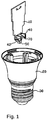
- Fig. 1 is a perspective exploded diagram of a electrical connection structure of light bulb cap of a first embodiment according to the present invention.
- the electrical connection structure of light bulb cap includes a driver plate 10 and a bulb head body 20.
- the bulb head body 20 is a housing structure with a top opening.
- the sidewall of the bulb head body 20 forms a first electrode terminal 30.
- the bottom of the driver plate 10 is placed inside the bulb head body 20.
- the electrical connection structure of light bulb cap also includes a connection base 40 and a first electrode 50.
- connection base 40 is fixed on the driver plate 20.
- the connection base 40 has one or more than installation columns 43.
- the installation columns 43 have free ends with anti - loose elastic barbs 431.
- Installation through holes (not shown) are provided on the driver plate 10.
- the install columns 32 are inserted into the installation through holes (not shown) for hooking the anti - loose elastic barbs 431 on the driver plate 10 so as to fix the connection base 40 on the driver plate 10.
- the connection base 40 may be made of insulation material.
- the first electrode 50 has a fixing end 51 and a connecting end 52.
- the fixing end 51 of the first electrode extends through the embedding trench 41 to electrically connect to the driver plate 10.
- the fixing end 51 of the first electrode 50 is a plug need structure.
- a plug hole is provided on the driver plate 10.
- the fixing end 51 extends through the embedding trench 41 to be welded in the plug hole so as to be electrically connected to the driver circuit on the driver plate 10.
- the connecting end 52 of the first electrode 50 is an elastic structure.
- the connecting end 52 of the first electrode is a bent metal elastic spring strip structure.
- the tail of the connecting end 52 of the first electrode may be a comb structure.
- the connecting end 52 of the first electrode elastically abuts on the inner sidewall of the first electrode terminal 30.
- a buffer portion 53 is smoothly provided between the fixing end 51 and the connecting end 52 of the first electrode 50.
- the buffer portion may be a 'U' arc shape structure.
- the buffer portion may reserve force.
- the buffer portion 53 provides a larger elastic deformation space when the connecting end 52 of the first electrode 50 abuts on the inner sidewall of the first electrode terminal 30 so as to ensure reliability of the connecting end 52 and facilitate assembling of the first electrode 50.
- a blocking lever 42 is disposed on the connection base 40. The blocking lever 42 abuts on the bended portion of the connecting end 52 to limit deformation of the connecting end 52.
- the electrical connection structure of light bulb cap further includes a second electrode terminal 60 and a second electrode 70.
- the second electrode 70 is fixed on the connection base 40.
- One end of the second electrode 70 is electrically connected to the driver plate 10.
- the other end of the second electrode 70 is an elastic connecting end 71.
- One end of the second electrode terminal 60 is fixed on the bulb head body 20 and insulated from the first electrode terminal 30.
- one end of the second electrode terminal 60 has a teeth structure 61.
- An insulation ring 21 is placed on the bulb head body 20.
- the insulation ring 21 is fixed at the bottom of the second electrode terminal 60.
- the second electrode terminal 60 use the teeth structure 61 to hook on the insulation ring 21.
- the other end of the second electrode terminal 60 is electrically connected to the elastic connecting end 71 of the second electrode 70.
- the connection base 60 has a groove 44 in its middle portion.
- the elastic connecting end 71 of the second electrode 70 extends into the groove 44.
- the other end of the second electrode terminal 60 extends into the groove 44 and abuts between the inner sidewall of the groove 44 and the elastic connecting end 72 of the second electrode 70 so as to ensure reliable connection between the second electrode terminal 60 and the second electrode 70.
- the electrical connection structure of light bulb cap has a connection base 40 as a socket base.
- the connection base 40 is fixed on the driver plate 10.
- a first electrode 50 is placed on the connection base 40.
- the fixing end 51 of the first electrode 50 is electrically connected to the driver plate 10.
- it is only needed to elastically about the connecting end 52 of the first electrode on the sidewall of the first electrode terminal 30 to achieve electrical connection of the electrical connection structure of light bulb cap.
- Such design ensures low cost of assembling, prevents complicated structures and facilitates automation process.
Landscapes
- Engineering & Computer Science (AREA)
- General Engineering & Computer Science (AREA)
- Microelectronics & Electronic Packaging (AREA)
- Physics & Mathematics (AREA)
- Optics & Photonics (AREA)
- Fastening Of Light Sources Or Lamp Holders (AREA)
Claims (10)
- Elektrische Verbindungsstruktur einer Glühbirnenkappe, umfassend:eine Treiberplatte (10);einen Lampenkopfkörper (20), wobei der Lampenkopfkörper (20) eine Gehäusestruktur mit einer oberen Öffnung ist, eine Seitenwand des Lampenkopfkörpers (20) einen ersten Elektrodenanschluss (30) bildet und der Boden der Treiberplatte (10) in der Innenseite des Lampenkopfkörpers (20) angeordnet ist ;eine erste Elektrode (50);eine Verbindungsbasis (40), die an der Treiberplatte (10) befestigt ist, wobei ein Einbettungsgraben (41) an der Verbindungsbasis (40) vorgesehen ist; undeine erste Elektrode (50) mit einem Befestigungsende (51) und einem Verbindungsende (52), wobei das Befestigungsende (51) der ersten Elektrode (50) durch den Einbettungsgraben (41) elektrisch mit der Treiberplatte (10) verbunden ist, das Verbindungsende (52) der ersten Elektrode (50) eine elastische Struktur ist und das Verbindungsende (52) der ersten Elektrode (50) liegt an einer inneren Seitenwand des ersten Elektrodenanschlusses (30) an,dadurch gekennzeichnet,dass ein Sperrhebel (42) an der Verbindungsbasis (40) angeordnet ist, der an einem gebogenen Abschnitt des Verbindungsendes (52) der ersten Elektrode (50) anliegt, um eine Verformung des Verbindungsendes (52) zu begrenzen.
- Elektrische Verbindungsstruktur einer Glühbirnenkappe nach Anspruch 1, wobei das Verbindungsende der ersten Elektrode eine gebogene elastische Metallfeder-Streifenstruktur ist.
- Elektrische Verbindungsstruktur einer Glühbirnenkappe nach Anspruch 2, wobei das Befestigungsende der ersten Elektrode eine Stecknadelstruktur ist, die Treiberplatte mit einem Steckloch versehen ist und das Befestigungsende der ersten Elektrode in das Steckloch durch den Einbettungsgraben eingeschweißt ist, um mit einer Treiberschaltung auf der Treiberplatte elektrisch verbunden zu sein.
- Elektrische Verbindungsstruktur einer Glühbirnenkappe nach Anspruch 2, wobei das Verbindungsende der ersten Elektrode einen Schwanz mit einer Kammstruktur aufweist.
- Elektrische Verbindungsstruktur einer Glühbirnenkappe nach Anspruch 1, wobei eine Installationssäule an der Verbindungsbasis angeordnet ist, ein freies Ende der Installationssäule mit einem losen elastischen Widerhaken versehen ist und ein Installationsdurchgangsloch an der Treiberplatte vorgesehen ist, die Installationssäule in die Durchgangsbohrung eingeführt ist, um die Treiberplatte mit dem elastischen Widerhaken zu verhaken, um die Verbindungsbasis an der Treiberplatte zu befestigen.
- Elektrische Verbindungsstruktur einer Glühbirnenkappe nach Anspruch 1, ferner umfassend einen zweiten Elektrodenanschluss und eine zweite Elektrode, wobei die zweite Elektrode an der Verbindungsbasis befestigt ist, ein Ende der zweiten Elektrode elektrisch mit der Treiberplatte verbunden ist, das andere Ende der zweiten Elektrode ist ein elastisches Verbindungsende, ein Ende des zweiten Elektrodenanschlusses ist an dem Lampenkopfkörper befestigt und von dem ersten Elektrodenanschluss isoliert, und das andere Ende des zweiten Elektrodenanschlusses ist elektrisch mit dem elastischen Verbindungsende der zweiten Elektrode verbunden.
- Elektrische Verbindungsstruktur einer Glühbirnenkappe nach Anspruch 6, wobei ein Ende des zweiten Elektrodenanschlusses mit einer Zahnstruktur versehen ist, ein Isolationsring am Glühbirnenkopfkörper angeordnet ist und der Isolationsring am Boden der ersten Elektrodenanschlusses befestigt ist und der zweite Elektrodenanschluss ist über die Zahnstruktur am Isolationsring eingehakt.
- Elektrische Verbindungsstruktur einer Glühbirnenkappe nach Anspruch 1, wobei die Verbindungsbasis aus Isolationsmaterial besteht.
- Elektrische Verbindungsstruktur einer Glühbirnenkappe nach Anspruch 1, wobei ein Pufferabschnitt glatt zwischen dem Befestigungsende und dem Verbindungsende der ersten Elektrode vorgesehen ist und der Pufferabschnitt eine "U"-Bogenformstruktur aufweist.
- Elektrische Verbindungsstruktur einer Glühbirnenkappe nach Anspruch 6, wobei ein mittlerer Abschnitt der Verbindungsbasis mit einer Nut versehen ist, das elastische Verbindungsende der zweiten Elektrode sich in die Nut erstreckt, und das andere Ende der zweiten Elektrode sich in die Nut erstreckt und liegt zwischen einer inneren Seitenwand der Nut und dem elastischen Verbindungsende der zweiten Elektrode an.
Applications Claiming Priority (2)
| Application Number | Priority Date | Filing Date | Title |
|---|---|---|---|
| CN201510355451.1A CN104930467A (zh) | 2015-06-25 | 2015-06-25 | 灯头电连接结构 |
| PCT/CN2016/085393 WO2016206541A1 (zh) | 2015-06-25 | 2016-06-11 | 灯头电连接结构 |
Publications (3)
| Publication Number | Publication Date |
|---|---|
| EP3309452A1 EP3309452A1 (de) | 2018-04-18 |
| EP3309452A4 EP3309452A4 (de) | 2018-05-02 |
| EP3309452B1 true EP3309452B1 (de) | 2019-07-24 |
Family
ID=54117754
Family Applications (1)
| Application Number | Title | Priority Date | Filing Date |
|---|---|---|---|
| EP16813657.0A Active EP3309452B1 (de) | 2015-06-25 | 2016-06-11 | Elektrische verbindungsstruktur eines glühlampensockels |
Country Status (4)
| Country | Link |
|---|---|
| US (1) | US9966718B2 (de) |
| EP (1) | EP3309452B1 (de) |
| CN (1) | CN104930467A (de) |
| WO (1) | WO2016206541A1 (de) |
Families Citing this family (10)
| Publication number | Priority date | Publication date | Assignee | Title |
|---|---|---|---|---|
| CN104676513A (zh) * | 2015-03-27 | 2015-06-03 | 立达信绿色照明股份有限公司 | 灯头电连接结构 |
| CN104930467A (zh) * | 2015-06-25 | 2015-09-23 | 厦门李氏兄弟有限公司 | 灯头电连接结构 |
| CN105202500B (zh) * | 2015-10-14 | 2018-09-18 | 赵德仁 | 一种灯头电连接结构 |
| CN105485646A (zh) * | 2015-12-31 | 2016-04-13 | 漳州立达信光电子科技有限公司 | 灯头电连接结构 |
| CN106016199A (zh) * | 2016-07-12 | 2016-10-12 | 奥其斯科技股份有限公司 | 电源板与灯头的电连接结构 |
| US9897264B1 (en) * | 2017-06-02 | 2018-02-20 | Xiamen Ghgm Industrial Trade Co., Ltd. | Negative connecting terminal and negative connector for LED bulb drive board and lamp cap |
| CN109882811B (zh) * | 2019-04-18 | 2024-11-05 | 厦门广泓工贸有限公司 | 一种灯座 |
| CN209929501U (zh) * | 2019-05-23 | 2020-01-10 | 漳州立达信光电子科技有限公司 | 一种驱动输入端子结构及灯具 |
| US10788165B1 (en) * | 2019-09-16 | 2020-09-29 | Consumer Lighting (U.S.), Llc | End cap assembly, lamp using the end cap and assembling method of the lamp |
| ES2843055B2 (es) * | 2020-01-14 | 2022-02-02 | Atressa Global Corp S L | Dispositivo perfeccionado de conexion electrica |
Family Cites Families (15)
| Publication number | Priority date | Publication date | Assignee | Title |
|---|---|---|---|---|
| US8042961B2 (en) * | 2007-12-02 | 2011-10-25 | Andrew Massara | Audio lamp |
| US20120217870A1 (en) * | 2011-02-24 | 2012-08-30 | Soni Vimal J | LED Light Assembly |
| US9140441B2 (en) * | 2012-08-15 | 2015-09-22 | Cree, Inc. | LED downlight |
| US9702530B2 (en) * | 2013-03-11 | 2017-07-11 | Philips Lighting Holding B.V. | Base for an electrical lamp and a method of assembling a base for an electrical lamp |
| US9310061B2 (en) * | 2013-08-30 | 2016-04-12 | Tyco Electronics Corporation | Light bulb assembly |
| US9151480B2 (en) * | 2013-08-30 | 2015-10-06 | Tyco Electronics Corporation | Light bulb assembly |
| US9151451B2 (en) * | 2013-09-09 | 2015-10-06 | Amphenol Ltw Technology Co., Ltd. | LED bulb and lamp head assembly with positioning structures |
| CN103939859B (zh) * | 2014-04-30 | 2016-02-03 | 东莞雅士电子有限公司 | Led灯的组装方法 |
| CN204026584U (zh) * | 2014-06-04 | 2014-12-17 | 立达信绿色照明股份有限公司 | 插口式灯头体 |
| CN203980204U (zh) * | 2014-07-18 | 2014-12-03 | 厦门阳光恩耐照明有限公司 | 一种驱动电源连接器和led灯具 |
| CN203979972U (zh) * | 2014-08-01 | 2014-12-03 | 乐清市健坤接插件有限公司 | 一种免焊接led球泡灯 |
| CN104154443A (zh) * | 2014-08-01 | 2014-11-19 | 乐清市健坤接插件有限公司 | 一种免焊接led球泡灯 |
| CN104676513A (zh) * | 2015-03-27 | 2015-06-03 | 立达信绿色照明股份有限公司 | 灯头电连接结构 |
| CN104930467A (zh) * | 2015-06-25 | 2015-09-23 | 厦门李氏兄弟有限公司 | 灯头电连接结构 |
| CN204786196U (zh) * | 2015-06-25 | 2015-11-18 | 厦门李氏兄弟有限公司 | 灯头电连接结构 |
-
2015
- 2015-06-25 CN CN201510355451.1A patent/CN104930467A/zh active Pending
-
2016
- 2016-06-11 WO PCT/CN2016/085393 patent/WO2016206541A1/zh not_active Ceased
- 2016-06-11 EP EP16813657.0A patent/EP3309452B1/de active Active
- 2016-06-24 US US15/192,878 patent/US9966718B2/en active Active
Non-Patent Citations (1)
| Title |
|---|
| None * |
Also Published As
| Publication number | Publication date |
|---|---|
| CN104930467A (zh) | 2015-09-23 |
| WO2016206541A1 (zh) | 2016-12-29 |
| US9966718B2 (en) | 2018-05-08 |
| EP3309452A4 (de) | 2018-05-02 |
| US20160380400A1 (en) | 2016-12-29 |
| EP3309452A1 (de) | 2018-04-18 |
Similar Documents
| Publication | Publication Date | Title |
|---|---|---|
| EP3309452B1 (de) | Elektrische verbindungsstruktur eines glühlampensockels | |
| US8415895B2 (en) | Lamp comprising a base and at least one light-emitting semiconductor component | |
| US9153882B2 (en) | Connector having a cylindrical section with a contact connected to an electrical wire therein | |
| US8963410B2 (en) | LED bulb | |
| US7736194B1 (en) | Universal electrical plug | |
| US20160061423A1 (en) | Light emitting diode lamp and lamp holder | |
| US7896666B2 (en) | Socket with securely fixed connecting rings | |
| US10186793B2 (en) | Light cap electrical connection structure | |
| US20180195899A1 (en) | Light sensor assembly | |
| EP3260774A1 (de) | Elektrisches verbindungselement | |
| EP3132182B1 (de) | Lampenvorrichtung, led-lampe und leuchte | |
| CN204786196U (zh) | 灯头电连接结构 | |
| US10612728B2 (en) | LED light bulb assembly and method for manufacturing same | |
| US20200248899A1 (en) | Integrated electrical connector device structure of led light | |
| JP5159409B2 (ja) | ホイップアンテナ | |
| US8690606B2 (en) | Electrical interface and method | |
| JP6681655B2 (ja) | 同軸コネクタ | |
| TW201724671A (zh) | 同軸電纜連接器、具有載體之同軸電纜連接器、及同軸電纜連接器的製造方法 | |
| CN112271521A (zh) | 一种新式灯头结构 | |
| JP2018148186A (ja) | 発光装置 | |
| KR101622025B1 (ko) | 엘이디 홀더 | |
| EP3832192B1 (de) | Lichtband | |
| JP3135408U (ja) | 捻回式ランプのランプベース | |
| CN107978883A (zh) | 电连接结构 | |
| CN105485646A (zh) | 灯头电连接结构 |
Legal Events
| Date | Code | Title | Description |
|---|---|---|---|
| STAA | Information on the status of an ep patent application or granted ep patent |
Free format text: STATUS: THE INTERNATIONAL PUBLICATION HAS BEEN MADE |
|
| PUAI | Public reference made under article 153(3) epc to a published international application that has entered the european phase |
Free format text: ORIGINAL CODE: 0009012 |
|
| STAA | Information on the status of an ep patent application or granted ep patent |
Free format text: STATUS: REQUEST FOR EXAMINATION WAS MADE |
|
| 17P | Request for examination filed |
Effective date: 20180109 |
|
| AK | Designated contracting states |
Kind code of ref document: A1 Designated state(s): AL AT BE BG CH CY CZ DE DK EE ES FI FR GB GR HR HU IE IS IT LI LT LU LV MC MK MT NL NO PL PT RO RS SE SI SK SM TR |
|
| AX | Request for extension of the european patent |
Extension state: BA ME |
|
| A4 | Supplementary search report drawn up and despatched |
Effective date: 20180329 |
|
| RIC1 | Information provided on ipc code assigned before grant |
Ipc: F21K 9/238 20160101ALI20180323BHEP Ipc: F21V 23/06 20060101ALI20180323BHEP Ipc: H01R 33/945 20060101ALI20180323BHEP Ipc: F21K 9/235 20160101ALI20180323BHEP Ipc: F21V 17/16 20060101AFI20180323BHEP Ipc: F21Y 115/10 20160101ALN20180323BHEP |
|
| RAP1 | Party data changed (applicant data changed or rights of an application transferred) |
Owner name: LEEDARSON LIGHTING CO., LTD. |
|
| DAV | Request for validation of the european patent (deleted) | ||
| DAX | Request for extension of the european patent (deleted) | ||
| RIC1 | Information provided on ipc code assigned before grant |
Ipc: F21V 17/16 20060101AFI20181205BHEP Ipc: F21V 23/06 20060101ALI20181205BHEP Ipc: F21Y 115/10 20160101ALN20181205BHEP Ipc: F21K 9/238 20160101ALI20181205BHEP Ipc: H01R 33/945 20060101ALI20181205BHEP Ipc: F21K 9/235 20160101ALI20181205BHEP |
|
| RIC1 | Information provided on ipc code assigned before grant |
Ipc: F21K 9/238 20160101ALI20181212BHEP Ipc: F21V 17/16 20060101AFI20181212BHEP Ipc: F21Y 115/10 20160101ALN20181212BHEP Ipc: F21K 9/235 20160101ALI20181212BHEP Ipc: H01R 33/945 20060101ALI20181212BHEP Ipc: F21V 23/06 20060101ALI20181212BHEP |
|
| GRAP | Despatch of communication of intention to grant a patent |
Free format text: ORIGINAL CODE: EPIDOSNIGR1 |
|
| STAA | Information on the status of an ep patent application or granted ep patent |
Free format text: STATUS: GRANT OF PATENT IS INTENDED |
|
| INTG | Intention to grant announced |
Effective date: 20190121 |
|
| GRAS | Grant fee paid |
Free format text: ORIGINAL CODE: EPIDOSNIGR3 |
|
| GRAA | (expected) grant |
Free format text: ORIGINAL CODE: 0009210 |
|
| STAA | Information on the status of an ep patent application or granted ep patent |
Free format text: STATUS: THE PATENT HAS BEEN GRANTED |
|
| AK | Designated contracting states |
Kind code of ref document: B1 Designated state(s): AL AT BE BG CH CY CZ DE DK EE ES FI FR GB GR HR HU IE IS IT LI LT LU LV MC MK MT NL NO PL PT RO RS SE SI SK SM TR |
|
| REG | Reference to a national code |
Ref country code: GB Ref legal event code: FG4D |
|
| REG | Reference to a national code |
Ref country code: CH Ref legal event code: EP |
|
| REG | Reference to a national code |
Ref country code: DE Ref legal event code: R096 Ref document number: 602016017519 Country of ref document: DE |
|
| REG | Reference to a national code |
Ref country code: AT Ref legal event code: REF Ref document number: 1158630 Country of ref document: AT Kind code of ref document: T Effective date: 20190815 |
|
| REG | Reference to a national code |
Ref country code: IE Ref legal event code: FG4D |
|
| REG | Reference to a national code |
Ref country code: DE Ref legal event code: R082 Ref document number: 602016017519 Country of ref document: DE Representative=s name: SCHMID, MICHAEL, DIPL.-ING. UNIV., DE |
|
| REG | Reference to a national code |
Ref country code: NL Ref legal event code: MP Effective date: 20190724 |
|
| REG | Reference to a national code |
Ref country code: LT Ref legal event code: MG4D |
|
| REG | Reference to a national code |
Ref country code: AT Ref legal event code: MK05 Ref document number: 1158630 Country of ref document: AT Kind code of ref document: T Effective date: 20190724 |
|
| PG25 | Lapsed in a contracting state [announced via postgrant information from national office to epo] |
Ref country code: NO Free format text: LAPSE BECAUSE OF FAILURE TO SUBMIT A TRANSLATION OF THE DESCRIPTION OR TO PAY THE FEE WITHIN THE PRESCRIBED TIME-LIMIT Effective date: 20191024 Ref country code: BG Free format text: LAPSE BECAUSE OF FAILURE TO SUBMIT A TRANSLATION OF THE DESCRIPTION OR TO PAY THE FEE WITHIN THE PRESCRIBED TIME-LIMIT Effective date: 20191024 Ref country code: HR Free format text: LAPSE BECAUSE OF FAILURE TO SUBMIT A TRANSLATION OF THE DESCRIPTION OR TO PAY THE FEE WITHIN THE PRESCRIBED TIME-LIMIT Effective date: 20190724 Ref country code: SE Free format text: LAPSE BECAUSE OF FAILURE TO SUBMIT A TRANSLATION OF THE DESCRIPTION OR TO PAY THE FEE WITHIN THE PRESCRIBED TIME-LIMIT Effective date: 20190724 Ref country code: FI Free format text: LAPSE BECAUSE OF FAILURE TO SUBMIT A TRANSLATION OF THE DESCRIPTION OR TO PAY THE FEE WITHIN THE PRESCRIBED TIME-LIMIT Effective date: 20190724 Ref country code: LT Free format text: LAPSE BECAUSE OF FAILURE TO SUBMIT A TRANSLATION OF THE DESCRIPTION OR TO PAY THE FEE WITHIN THE PRESCRIBED TIME-LIMIT Effective date: 20190724 Ref country code: PT Free format text: LAPSE BECAUSE OF FAILURE TO SUBMIT A TRANSLATION OF THE DESCRIPTION OR TO PAY THE FEE WITHIN THE PRESCRIBED TIME-LIMIT Effective date: 20191125 Ref country code: NL Free format text: LAPSE BECAUSE OF FAILURE TO SUBMIT A TRANSLATION OF THE DESCRIPTION OR TO PAY THE FEE WITHIN THE PRESCRIBED TIME-LIMIT Effective date: 20190724 Ref country code: AT Free format text: LAPSE BECAUSE OF FAILURE TO SUBMIT A TRANSLATION OF THE DESCRIPTION OR TO PAY THE FEE WITHIN THE PRESCRIBED TIME-LIMIT Effective date: 20190724 |
|
| PG25 | Lapsed in a contracting state [announced via postgrant information from national office to epo] |
Ref country code: ES Free format text: LAPSE BECAUSE OF FAILURE TO SUBMIT A TRANSLATION OF THE DESCRIPTION OR TO PAY THE FEE WITHIN THE PRESCRIBED TIME-LIMIT Effective date: 20190724 Ref country code: LV Free format text: LAPSE BECAUSE OF FAILURE TO SUBMIT A TRANSLATION OF THE DESCRIPTION OR TO PAY THE FEE WITHIN THE PRESCRIBED TIME-LIMIT Effective date: 20190724 Ref country code: AL Free format text: LAPSE BECAUSE OF FAILURE TO SUBMIT A TRANSLATION OF THE DESCRIPTION OR TO PAY THE FEE WITHIN THE PRESCRIBED TIME-LIMIT Effective date: 20190724 Ref country code: RS Free format text: LAPSE BECAUSE OF FAILURE TO SUBMIT A TRANSLATION OF THE DESCRIPTION OR TO PAY THE FEE WITHIN THE PRESCRIBED TIME-LIMIT Effective date: 20190724 Ref country code: IS Free format text: LAPSE BECAUSE OF FAILURE TO SUBMIT A TRANSLATION OF THE DESCRIPTION OR TO PAY THE FEE WITHIN THE PRESCRIBED TIME-LIMIT Effective date: 20191124 Ref country code: GR Free format text: LAPSE BECAUSE OF FAILURE TO SUBMIT A TRANSLATION OF THE DESCRIPTION OR TO PAY THE FEE WITHIN THE PRESCRIBED TIME-LIMIT Effective date: 20191025 |
|
| PG25 | Lapsed in a contracting state [announced via postgrant information from national office to epo] |
Ref country code: TR Free format text: LAPSE BECAUSE OF FAILURE TO SUBMIT A TRANSLATION OF THE DESCRIPTION OR TO PAY THE FEE WITHIN THE PRESCRIBED TIME-LIMIT Effective date: 20190724 |
|
| PG25 | Lapsed in a contracting state [announced via postgrant information from national office to epo] |
Ref country code: RO Free format text: LAPSE BECAUSE OF FAILURE TO SUBMIT A TRANSLATION OF THE DESCRIPTION OR TO PAY THE FEE WITHIN THE PRESCRIBED TIME-LIMIT Effective date: 20190724 Ref country code: PL Free format text: LAPSE BECAUSE OF FAILURE TO SUBMIT A TRANSLATION OF THE DESCRIPTION OR TO PAY THE FEE WITHIN THE PRESCRIBED TIME-LIMIT Effective date: 20190724 Ref country code: EE Free format text: LAPSE BECAUSE OF FAILURE TO SUBMIT A TRANSLATION OF THE DESCRIPTION OR TO PAY THE FEE WITHIN THE PRESCRIBED TIME-LIMIT Effective date: 20190724 Ref country code: IT Free format text: LAPSE BECAUSE OF FAILURE TO SUBMIT A TRANSLATION OF THE DESCRIPTION OR TO PAY THE FEE WITHIN THE PRESCRIBED TIME-LIMIT Effective date: 20190724 Ref country code: DK Free format text: LAPSE BECAUSE OF FAILURE TO SUBMIT A TRANSLATION OF THE DESCRIPTION OR TO PAY THE FEE WITHIN THE PRESCRIBED TIME-LIMIT Effective date: 20190724 |
|
| PG25 | Lapsed in a contracting state [announced via postgrant information from national office to epo] |
Ref country code: IS Free format text: LAPSE BECAUSE OF FAILURE TO SUBMIT A TRANSLATION OF THE DESCRIPTION OR TO PAY THE FEE WITHIN THE PRESCRIBED TIME-LIMIT Effective date: 20200224 Ref country code: SM Free format text: LAPSE BECAUSE OF FAILURE TO SUBMIT A TRANSLATION OF THE DESCRIPTION OR TO PAY THE FEE WITHIN THE PRESCRIBED TIME-LIMIT Effective date: 20190724 Ref country code: SK Free format text: LAPSE BECAUSE OF FAILURE TO SUBMIT A TRANSLATION OF THE DESCRIPTION OR TO PAY THE FEE WITHIN THE PRESCRIBED TIME-LIMIT Effective date: 20190724 Ref country code: CZ Free format text: LAPSE BECAUSE OF FAILURE TO SUBMIT A TRANSLATION OF THE DESCRIPTION OR TO PAY THE FEE WITHIN THE PRESCRIBED TIME-LIMIT Effective date: 20190724 |
|
| REG | Reference to a national code |
Ref country code: DE Ref legal event code: R097 Ref document number: 602016017519 Country of ref document: DE |
|
| PLBE | No opposition filed within time limit |
Free format text: ORIGINAL CODE: 0009261 |
|
| STAA | Information on the status of an ep patent application or granted ep patent |
Free format text: STATUS: NO OPPOSITION FILED WITHIN TIME LIMIT |
|
| PG2D | Information on lapse in contracting state deleted |
Ref country code: IS |
|
| 26N | No opposition filed |
Effective date: 20200603 |
|
| PG25 | Lapsed in a contracting state [announced via postgrant information from national office to epo] |
Ref country code: SI Free format text: LAPSE BECAUSE OF FAILURE TO SUBMIT A TRANSLATION OF THE DESCRIPTION OR TO PAY THE FEE WITHIN THE PRESCRIBED TIME-LIMIT Effective date: 20190724 |
|
| PG25 | Lapsed in a contracting state [announced via postgrant information from national office to epo] |
Ref country code: MC Free format text: LAPSE BECAUSE OF FAILURE TO SUBMIT A TRANSLATION OF THE DESCRIPTION OR TO PAY THE FEE WITHIN THE PRESCRIBED TIME-LIMIT Effective date: 20190724 |
|
| REG | Reference to a national code |
Ref country code: CH Ref legal event code: PL |
|
| PG25 | Lapsed in a contracting state [announced via postgrant information from national office to epo] |
Ref country code: LU Free format text: LAPSE BECAUSE OF NON-PAYMENT OF DUE FEES Effective date: 20200611 |
|
| REG | Reference to a national code |
Ref country code: BE Ref legal event code: MM Effective date: 20200630 |
|
| PG25 | Lapsed in a contracting state [announced via postgrant information from national office to epo] |
Ref country code: IE Free format text: LAPSE BECAUSE OF NON-PAYMENT OF DUE FEES Effective date: 20200611 Ref country code: LI Free format text: LAPSE BECAUSE OF NON-PAYMENT OF DUE FEES Effective date: 20200630 Ref country code: CH Free format text: LAPSE BECAUSE OF NON-PAYMENT OF DUE FEES Effective date: 20200630 |
|
| PG25 | Lapsed in a contracting state [announced via postgrant information from national office to epo] |
Ref country code: BE Free format text: LAPSE BECAUSE OF NON-PAYMENT OF DUE FEES Effective date: 20200630 |
|
| PG25 | Lapsed in a contracting state [announced via postgrant information from national office to epo] |
Ref country code: MT Free format text: LAPSE BECAUSE OF FAILURE TO SUBMIT A TRANSLATION OF THE DESCRIPTION OR TO PAY THE FEE WITHIN THE PRESCRIBED TIME-LIMIT Effective date: 20190724 Ref country code: CY Free format text: LAPSE BECAUSE OF FAILURE TO SUBMIT A TRANSLATION OF THE DESCRIPTION OR TO PAY THE FEE WITHIN THE PRESCRIBED TIME-LIMIT Effective date: 20190724 |
|
| PG25 | Lapsed in a contracting state [announced via postgrant information from national office to epo] |
Ref country code: MK Free format text: LAPSE BECAUSE OF FAILURE TO SUBMIT A TRANSLATION OF THE DESCRIPTION OR TO PAY THE FEE WITHIN THE PRESCRIBED TIME-LIMIT Effective date: 20190724 |
|
| PGFP | Annual fee paid to national office [announced via postgrant information from national office to epo] |
Ref country code: DE Payment date: 20250428 Year of fee payment: 10 |
|
| PGFP | Annual fee paid to national office [announced via postgrant information from national office to epo] |
Ref country code: GB Payment date: 20250408 Year of fee payment: 10 |
|
| PGFP | Annual fee paid to national office [announced via postgrant information from national office to epo] |
Ref country code: FR Payment date: 20260331 Year of fee payment: 11 |