EP3309587B1 - Système et procédé de positionnement - Google Patents
Système et procédé de positionnement Download PDFInfo
- Publication number
- EP3309587B1 EP3309587B1 EP17195463.9A EP17195463A EP3309587B1 EP 3309587 B1 EP3309587 B1 EP 3309587B1 EP 17195463 A EP17195463 A EP 17195463A EP 3309587 B1 EP3309587 B1 EP 3309587B1
- Authority
- EP
- European Patent Office
- Prior art keywords
- gps
- information
- gps satellite
- satellite
- received
- Prior art date
- Legal status (The legal status is an assumption and is not a legal conclusion. Google has not performed a legal analysis and makes no representation as to the accuracy of the status listed.)
- Active
Links
Images







Classifications
-
- G—PHYSICS
- G01—MEASURING; TESTING
- G01S—RADIO DIRECTION-FINDING; RADIO NAVIGATION; DETERMINING DISTANCE OR VELOCITY BY USE OF RADIO WAVES; LOCATING OR PRESENCE-DETECTING BY USE OF THE REFLECTION OR RERADIATION OF RADIO WAVES; ANALOGOUS ARRANGEMENTS USING OTHER WAVES
- G01S19/00—Satellite radio beacon positioning systems; Determining position, velocity or attitude using signals transmitted by such systems
- G01S19/38—Determining a navigation solution using signals transmitted by a satellite radio beacon positioning system
- G01S19/39—Determining a navigation solution using signals transmitted by a satellite radio beacon positioning system the satellite radio beacon positioning system transmitting time-stamped messages, e.g. GPS [Global Positioning System], GLONASS [Global Orbiting Navigation Satellite System] or GALILEO
- G01S19/42—Determining position
-
- G—PHYSICS
- G01—MEASURING; TESTING
- G01S—RADIO DIRECTION-FINDING; RADIO NAVIGATION; DETERMINING DISTANCE OR VELOCITY BY USE OF RADIO WAVES; LOCATING OR PRESENCE-DETECTING BY USE OF THE REFLECTION OR RERADIATION OF RADIO WAVES; ANALOGOUS ARRANGEMENTS USING OTHER WAVES
- G01S19/00—Satellite radio beacon positioning systems; Determining position, velocity or attitude using signals transmitted by such systems
- G01S19/01—Satellite radio beacon positioning systems transmitting time-stamped messages, e.g. GPS [Global Positioning System], GLONASS [Global Orbiting Navigation Satellite System] or GALILEO
- G01S19/13—Receivers
- G01S19/14—Receivers specially adapted for specific applications
-
- G—PHYSICS
- G01—MEASURING; TESTING
- G01S—RADIO DIRECTION-FINDING; RADIO NAVIGATION; DETERMINING DISTANCE OR VELOCITY BY USE OF RADIO WAVES; LOCATING OR PRESENCE-DETECTING BY USE OF THE REFLECTION OR RERADIATION OF RADIO WAVES; ANALOGOUS ARRANGEMENTS USING OTHER WAVES
- G01S19/00—Satellite radio beacon positioning systems; Determining position, velocity or attitude using signals transmitted by such systems
- G01S19/01—Satellite radio beacon positioning systems transmitting time-stamped messages, e.g. GPS [Global Positioning System], GLONASS [Global Orbiting Navigation Satellite System] or GALILEO
- G01S19/13—Receivers
- G01S19/24—Acquisition or tracking or demodulation of signals transmitted by the system
-
- G—PHYSICS
- G01—MEASURING; TESTING
- G01S—RADIO DIRECTION-FINDING; RADIO NAVIGATION; DETERMINING DISTANCE OR VELOCITY BY USE OF RADIO WAVES; LOCATING OR PRESENCE-DETECTING BY USE OF THE REFLECTION OR RERADIATION OF RADIO WAVES; ANALOGOUS ARRANGEMENTS USING OTHER WAVES
- G01S19/00—Satellite radio beacon positioning systems; Determining position, velocity or attitude using signals transmitted by such systems
- G01S19/38—Determining a navigation solution using signals transmitted by a satellite radio beacon positioning system
- G01S19/39—Determining a navigation solution using signals transmitted by a satellite radio beacon positioning system the satellite radio beacon positioning system transmitting time-stamped messages, e.g. GPS [Global Positioning System], GLONASS [Global Orbiting Navigation Satellite System] or GALILEO
- G01S19/42—Determining position
- G01S19/421—Determining position by combining or switching between position solutions or signals derived from different satellite radio beacon positioning systems; by combining or switching between position solutions or signals derived from different modes of operation in a single system
- G01S19/426—Determining position by combining or switching between position solutions or signals derived from different satellite radio beacon positioning systems; by combining or switching between position solutions or signals derived from different modes of operation in a single system by combining or switching between position solutions or signals derived from different modes of operation in a single system
-
- F—MECHANICAL ENGINEERING; LIGHTING; HEATING; WEAPONS; BLASTING
- F21—LIGHTING
- F21W—INDEXING SCHEME ASSOCIATED WITH SUBCLASSES F21K, F21L, F21S and F21V, RELATING TO USES OR APPLICATIONS OF LIGHTING DEVICES OR SYSTEMS
- F21W2131/00—Use or application of lighting devices or systems not provided for in codes F21W2102/00-F21W2121/00
- F21W2131/10—Outdoor lighting
Definitions
- the invention relates to a positioning system and a method for positioning.
- the present invention also relates to a device (e.g. an outdoor lighting system or a portable device) using such a positioning system.
- GPS systems are used in a wide variety of applications.
- Such conventional systems include a GPS receiver that is able to receive GPS satellite signals from GPS satellites in the sky.
- the satellites carry stable atomic clocks that are synchronized to each other and to ground clocks, and drift from true time maintained on the ground is corrected daily.
- the satellite locations are known with precision.
- a GPS receiver can receive GPS signals from multiple satellites and can determine its position and its deviation from true time. At a minimum, four satellites must be in view of the receiver for it to compute four unknown quantities (three position coordinates and clock deviation from satellite time). However, the position accuracy of conventional GPS systems is limited to a few meters.
- EP 1 881 336 A1 discloses a positioning device which receives a satellite signal from a satellite positioning system (SPS) satellite and locates a present position.
- the positioning device includes an azimuth calculation section which calculates an azimuth of the SPS satellite corresponding to the received satellite signal, and a reception environment determination section which determines a reception environment including a multipath environment based on the azimuths of the SPS satellites calculated by the azimuth calculation section.
- SPS satellite positioning system
- EP 2 037 290 A1 relates to global positioning system (GPS) receivers, and more particularly to processing of SPS signals.
- a satellite elevation mask which may depend on a signal environment charaterization, may be applied in a satellite selection process to avoid using signals with large multipath errors at lower satellite elevation angles. Further, depending on the signal environment characterization, a signal-to-noise ratio mask or signal-to-interference ratio mask or estimated signal input strength or a combination of the three masks is used in operation to remove weak signals from further measurement processing.
- EP 1 729 145 A1 in the field of Global Navigation Satellite Systems (GNSS) receivers and/or GNSS-based applications discloses a method and system for providing GNSS navigation position solution with guaranteed integrity in non-controlled environments.
- the solution can be applied in a wide diversity of fields, whenever position/velocity information is used between two parties with liability (either legal, administrative or economical) implications.
- the document discloses using a threshold of minimum Carrier to Noise ratio as a function of satellite elevation to reject those satellites with signal power attenuated by trees canopy or by multipath with the carrier of the reflected signal in opposite phase.
- GNSS Multipath and Jamming Mitigation Using High-Mask-Angle Antennas and Multiple Constellations disclose using high mask-angle antennas (HMAAs) to counter RF interference.
- the antenna mask angle which is also referred to as the cutoff angle, is a parameter in the GNSS antenna design defining the elevation below which RF signals will be considerably attenuated.
- the HMAA method is based on the fact that multipath reflectors and jamming sources are mostly on the ground.
- An HMAA can suppress the interference and GNSS signals coming from low-elevation angles.
- the objective of the scientific paper is to find the optimum mask angle, which is defined as the highest mask angle with which the performance of multiple constellations is not worse than the performance of a single constellation with a standard low mask-angle antenna.
- US 2009/034258 A1 relates to an illumination system capable of providing multiple functions, such as illumination, globe positioning, energy saving, anti-theft, and precaution to natural disaster.
- a power supply unit is electrically connected to a GPS unit and a LED light source, while a control platform is electrically connected to the GPS unit, the LED light source, and the power supply unit.
- the invention is defined by a positioning system according to claim 1, a mobile device according to claim 12 and an outdoor lighting system according to claim 13.
- Preferred embodiments of the invention are defined by the dependent claims.
- a positioning system comprising: a GPS device including a GPS receiver arranged to receive GPS satellite signals from a plurality of GPS satellites and an attenuation device arranged to attenuate GPS satellite signals such that when a GPS satellite is located in a first portion of sky the GPS satellite signals received by the GPS receiver from said GPS satellite are attenuated; and a controller arranged to determine position information of the GPS device based on received GPS information from the GPS device.
- a positioning system comprising: a GPS device including a GPS receiver arranged to receive GPS satellite signals from a plurality of GPS satellites and an attenuation device arranged to attenuate GPS satellite signals such that when a GPS satellite is located in a first portion of sky the GPS satellite signals received by the GPS receiver from said GPS satellite are attenuated; a storage arranged to store satellite location information for the plurality of GPS satellites over time at a location of the GPS receiver; and a controller arranged to determine location information of the GPS device based on received GPS information from the GPS device, wherein the received GPS information comprises information on signal strengths of the GPS satellite signals received by the GPS receiver, wherein if a signal strength for a first GPS satellite is lower than a threshold signal strength at a point in time then the controller is arranged to determine that the first GPS satellite is in the first portion of the sky and determine angle information of the GPS device relative to earth's normal and/or orientation information of the GPS device in a horizontal plane using the stored satellite location information.
- the antenna radiation pattern can be made asymmetric by covering only a particular area of the sky so that incoming signals through that area are attenuated or blocked.
- the signal-to-noise ratio of the signals received from some of the satellite(s) is affected without influencing the azimuth or angle data.
- the attenuation device may be arranged to attenuate GPS satellite signals by blocking GPS satellite signals from GPS satellites located in the first portion of the sky from being received by the GPS receiver.
- the attenuation device may be made from a suitable GPS blocking material or from a conductive material.
- the attenuation device may comprise a portion of GPS satellite signal attenuating material located between the GPS receiver and the sky.
- the attenuation device may comprise a portion of GPS satellite signal reflecting material located close and at the opposite side of the satellite(s) seen from the GPS receiver, mostly under the GPS receiver.
- the attenuation device may be fixed in position relative to the GPS receiver.
- the satellite location information comprises reference angle information, reference azimuth information, and reference signal strength for the plurality of GPS satellites over time at the location of the GPS receiver, wherein the reference angle information, reference azimuth information, and the reference signal strength correspond to GPS satellite signals from the plurality of GPS satellites unattentuated by the attenuation device; wherein the controller is arranged to receive angle information, azimuth information, and signal strength for each of the plurality of GPS satellites from the GPS receiver; wherein the controller is arranged to compare the received signal strength with the reference signal strength for each of the plurality of GPS satellites; and wherein if the received signal strength for a first GPS satellite is lower than the reference signal strength for the first GPS satellite, then the controller is arranged to determine that the first GPS satellite is in the first portion of the sky and determine the angle information of the GPS device relative to earth's normal and/or the orientation information of the GPS device in a horizontal plane using the reference angle information and reference azimuth information.
- a GPS device can therefore provide orientation and angle information with separate
- the controller may be arranged to determine a change in the angle of the GPS device relative to earth's normal and/or a change in the orientation of the GPS device in a horizontal plane based on change in the determined angle information and/or orientation information.
- the controller may be arranged to determine a time of day when received GPS satellite signals from a GPS satellite become attenuated as a result of said GPS satellite passing through the first portion of the sky; wherein the controller is arranged to determine a change in orientation of the GPS device based on a change in the time of day when the received GPS satellite signals from said GPS satellite become attenuated.
- the attenuation device may have a first state in which the attenuation device does not attenuate GPS satellite signals, and a second state in which the attenuation device attenuates GPS satellite signals from the first portion of the sky.
- the attenuation device may comprises a first gauze, a second gauze on top of the first gauze, wherein the first gauze and the second gauze are not electrically connected in the first state, and wherein the first gauze and the second gauze are electrically connect the first gauze and the second gauze in the second state.
- the attenuation device may comprise at least one switch diode connected between the first gauze and the second gauze, wherein the at least one switch diode is arranged to electrically connect the first gauze and the second gauze in the second state.
- the positioning system may further comprise a second GPS device including a GPS receiver arranged to receive GPS satellite signals from a plurality of GPS satellites.
- the controller may be arranged to determine position information of the second GPS device based on received GPS information from the second GPS device. If the GPS device and the second GPS device are close, the controller may be arranged to distinguish the location of the GPS device from the location of the second GPS device on the basis of a difference in received GPS signals from the GPS device and the second GPS device. For example, a difference in SNR for a particular satellite measured at the second GPS device when compared to the GPS device would enable the GPS signals from the GPS device to be differentiated from the second GPS device. In other words, such embodiments enable a controller to identify two GPS devices in close proximity.
- a mobile device comprising: a positioning system according to any of the above aspects; wherein the controller is arranged to determine angle information of the GPS device relative to earth's normal and/or orientation information of the GPS device in a horizontal plane based on the received GPS information from the GPS device.
- an outdoor lighting system comprising: a positioning system according to any of the above aspects; an outdoor lighting apparatus comprising a lighting unit including the GPS device and one or more lights; wherein the controller is arranged to determine location information of the lighting unit based on the received GPS information from the GPS device.
- the outdoor lighting apparatus may comprise a pole on which the lighting unit is mounted.
- the outdoor lighting apparatus may further comprise a second lighting unit including a second GPS device and one or more second lights; wherein the second GPS device includes a second GPS receiver arranged to receive GPS satellite signals from the plurality of GPS satellites; wherein the controller is arranged to determine position information of the second lighting unit based on received GPS information from the second GPS device.
- a second lighting unit including a second GPS device and one or more second lights
- the second GPS device includes a second GPS receiver arranged to receive GPS satellite signals from the plurality of GPS satellites
- the controller is arranged to determine position information of the second lighting unit based on received GPS information from the second GPS device.
- the second lighting unit may be on the same pole as the first lighting unit.
- the second GPS device may include a second attenuation device arranged to attenuate GPS satellite signals such that when a GPS satellite is located in a second portion of the sky the GPS satellite signals received by the second GPS receiver for said GPS satellite are attenuated.
- the outdoor lighting system may further comprise: a second outdoor lighting apparatus comprising a third lighting unit including a third GPS device and one or more third lights; wherein the controller is arranged to determine position information of the third lighting unit based on received GPS information from the third GPS device.
- the third GPS device may further include a third attenuation device arranged to attenuate GPS satellite signals such that when a GPS satellite is located in a third portion of the sky the GPS satellite signals received by the third GPS receiver for said GPS satellite are attenuated.
- a third attenuation device arranged to attenuate GPS satellite signals such that when a GPS satellite is located in a third portion of the sky the GPS satellite signals received by the third GPS receiver for said GPS satellite are attenuated.
- the second outdoor light apparatus may comprise a second pole on which the third lighting unit is mounted.
- the location of the first outdoor light apparatus may be distinguished from the location of the second outdoor light apparatus on the basis of a difference in received GPS signals from the first outdoor light apparatus and the second outdoor light apparatus. For example, a difference in SNR for a particular satellite measured at the second outdoor light apparatus when compared to the first outdoor light apparatus would enable the GPS signals from the first outdoor light apparatus to be differentiated from the second outdoor light apparatus.
- the first outdoor light apparatus and the second outdoor light apparatus could be individually identified by the controller, even if their GPS receivers were close enough that a conventional GPS location reading would give the same result. In other words, such embodiments enable a controller to identify two outdoor light apparatuses on the same pole using only the GPS receivers.
- the outdoor lighting system may comprise a plurality of outdoor light apparatuses, each with a lighting unit including a GPS device and one or more lights.
- the outdoor lighting system may identify each lighting unit on the basis of the location of its GPS device.
- a positioning system comprising: a GPS device including a GPS receiver arranged to receive GPS satellite signals from a plurality of GPS satellites in order to determine location information of the GPS device, the received GPS satellite signals including angle information, azimuth information, and signal strength for the plurality of GPS satellites, and an attenuation device fixed relative to the GPS receiver arranged to attenuate GPS satellite signals received by the GPS receiver from a first portion of the sky; a storage arranged to store reference angle information, reference azimuth information, and reference signal strength for the plurality of GPS satellites at the location of the GPS receiver; a controller arranged to compare the received signal strength with the reference signal strength for each of the plurality of GPS satellites; wherein if the received signal strength for a first GPS satellite is lower than the reference signal strength, then the controller is arranged to determine that the first GPS satellite is in the first portion of the sky and determine an angle of the GPS device relative to earth's normal and an orientation of the GPS device in a horizontal plane based on the reference angle information and reference azimuth
- a positioning system comprising: a GPS device including a GPS receiver arranged to receive GPS satellite signals from a plurality of GPS satellites in order to determine location information of the GPS device, and an attenuation device arranged to attenuate GPS satellite signals received by the GPS receiver from a first portion of the sky; a controller is arranged to determine a time of day when received GPS satellite signals from a first GPS satellite become attenuated as a result of the first GPS satellite passing through the first portion of the sky; wherein the controller is arranged to determine a change in orientation of the GPS device based on a change in the time of day when the received GPS satellite signals from said GPS satellite become attenuated.
- a computer-implemented method of positioning system comprising: using a GPS device including a GPS receiver to receive GPS satellite signals from a plurality of GPS satellites, and using an attenuation device to attenuate GPS satellite signals such that when a GPS satellite is located in a first portion of sky the GPS satellite signals received by the GPS receiver from said GPS satellite are attenuated; and determining position information of the GPS device based on received GPS information from the GPS device.
- Figure 1 shows a positioning system 100 comprising a GPS device 110 and a controller 120.
- the GPS device 110 includes a GPS receiver 111 that is arranged to receive GPS satellite signals from a plurality of GPS satellites and an attenuation device 112. As will be explained in more detail below, the attenuation device 112 is arranged to attenuate GPS satellite signals. The attenuation device 112 is arranged such that when a particular GPS satellite is located in a particular portion of sky the GPS satellite signals received by the GPS receiver from that particular GPS satellite are attenuated (i.e. reduced or blocked).
- the controller 120 receives GPS information from the GPS device 110.
- the controller 120 is arranged to determine position information of the GPS device 110 based on received GPS information from the GPS device 110.
- the GPS device 110 and the controller 120 are shown as being part of the same device. However, in other embodiments the GPS device 110 and the controller 120 could be in separate devices with a suitable communications mechanism being used to connect them.
- the GPS device 110 and the controller 120 may be connected via an appropriate network such as the internet.
- FIGs 2A, 2B , 2C and 2D illustrate exemplary views of satellite constellations as determined by the same conventional GPS receiver at the same location at different times. So called $GPGSV data as part of the NMEA protocol can be plotted in terms of angle and azimuth to produce the graphs in Figures 2A-D .
- the GPS receiver receives all the signals from the available satellites simultaneously with the same antenna (not shown).
- each satellite At a certain moment in time the satellites are in a specific position.
- the signal strength per satellite is determined by the GPS receiver.
- Every numbered dot (referred to as the PRN) in Figures 2A, 2B , 2C and 2D represents a particular satellite in the sky above the GPS receiver 111, and each satellite is located at a slightly different position in each plot. This is because each plot represents the orientations of the satellites at different points in time and the satellites are moving.
- the signal at a GPS receiver received from a satellite should be strong enough to yield a signal-to-noise ratio (SNR) in a detectable range.
- SNR signal-to-noise ratio
- the signals from each satellite should be largely identical in strength. However, in reality this can be affected by various factors.
- a “symmetric” antenna radiation pattern refers to a situation where the strength of the signal received by the antenna is uniform regardless of the direction from which the signal is received, within the viewing range the antenna. In other words, the signal strength will not change even if the orientation of the antenna in the GPS receiver changes, as long as the satellite of interest is within the viewing range.
- the antenna radiation pattern is "asymmetric"
- the angular position of a satellite with respect to the specific antenna radiation pattern of the GPS receiver will influence the signal strength.
- the strength of the signal received from each satellite will depend on the orientation of the GPS receiver relative to the angular position of a particular satellite defined by azimuth and angle.
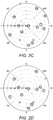
- Figures 3A , 3B and 3C show three plots of satellite signals as a function of signal-to-noise ratio (SNR) as received by three conventional GPS receivers with attached their three antennas, all of the same brand and type (i.e. without any deliberate attenuation), at different physical orientations but as close as possible to each other which means only a few cm apart.
- the three plots show that the strength of the signal from each satellite is different, but that the plots for each of the three different conventional GPS receivers are similar. In other words, the relative strength of the signals and the azimuth and angle reading of the satellites are very similar for all three conventional GPS receivers. Hence, it can be inferred from the graphs that the antenna radiation patterns of the conventional GPS receivers are largely symmetric.
- the attenuation device 112 is arranged such that when a particular GPS satellite is located in a particular portion of sky the GPS satellite signals received by the GPS receiver 111 from that particular GPS satellite are attenuated (i.e. reduced or blocked). In other words, the attenuation device 112 changes the antenna radiation pattern of the GPS receiver 111 so as to introduce deliberate asymmetry.
- the GPS receiver 111 requires signals from at least four of the satellites. Signals from more satellites can be used to increase accuracy. However, to obtain position reading with an acceptable accuracy does not require all the satellite signals in reception. By deliberately attenuating or blocking some signals received from some of the satellites, information on the orientation of a GPS receiver 111 can be obtained.
- the attenuation device 120 on the GPS receiver 111 establishes an asymmetric antenna pattern for the GPS receiver 111. This influences the signal-to-noise ratio of the received satellite signals, but does not influence the azimuth or angle data of the satellite signals, as long as the signal remains detectable.
- azimuth and angle data for the current position of the particular satellite are restored from the known orbit data of the particular satellite. This will be explained with reference to Figure 4 .
- Figure 4 shows the GPS receiver 111 of Figure 1 positioned close to the earth 10.
- the controller 120 is not shown for ease of explanation.
- Satellites 300A to 300H are within the viewing range of the GPS receiver 111. Since the GPS receiver 111 does not need all satellite signals for an accurate position reading as mentioned above, signals from satellites 300F, 300G, 300H, for example, can be attenuated or completely blocked by covering the antenna of the GPS receiver 111 with an attenuation device 112 and the GPS receiver 111 can still provide sufficient GPS satellite information for accurate positioning.
- the attenuation device 112 blocks GPS signals from only a particular area of the sky (in this example the area containing satellites 300F, 300G and 300H). Therefore, the signal strength of a particular satellite is heavily influenced depending on the angular position of the satellite with respect to the attenuation device 112. This renders the antenna radiation pattern heavily asymmetric.
- the satellites whose signals are attenuated or blocked can be referred to as being in the attenuated area AA of the sky, and the rest can be referred to as being non-attenuated area NAA.
- the satellites 300A, 300B, 300C, 300D and 300E are in the non-attenuated area NAA and the satellites 300F, 300G and 300H are in the attenuated area AA.
- the attenuation device 112 comprises a piece of material that covers a portion of the GPS receiver 111 that attenuates the radio waves at the frequencies of the satellite signals.
- the material could be a conductive material.
- One category includes blocking materials which reflect the EM waves from satellites, and are electrically conducting materials like copper, aluminum, iron, gold etc.
- Another category includes attenuating materials which partially dissipate EM waves (turn EM waves into heat) which are for instance ferrite, iron pentacarbonyl, electrically isolated carbonyl iron balls of specific dimensions suspended in a two-part epoxy paint, etc.
- the orientation data of the GPS receiver 111 can be obtained without adding significantly to the BOM (Bill of Materials) of the positioning system.
- the antenna radiation pattern can be made asymmetric by covering only a particular area of the sky so that incoming signals through that area are attenuated or blocked.
- the signal-to-noise ratio of the signals received from some of the satellite is affected without influencing the azimuth or angle data.
- the antenna radiation pattern is asymmetric, the strength of signals from one or more particular satellites is influenced depending on the angular position of those satellites with respect to the area of the attenuation or blocking.
- the signal-to-noise ratio of the signals received from the satellites in attenuated areas AA is affected while the signal-to-noise ratio of the signals received from the satellites in non-attenuated areas NAA is not.
- a positioning system using such a GPS receiver can provide location information as well as additional functionality. For example, it is known that position accuracy of conventional GPS systems is limited to a few meters. Hence, two conventional GPS receives within a couple of meters from each other will be determined to have the same location. However, it would be possible to distinguish between a GPS receiver 111 with the attenuation device 112 and a conventional GPS receiver based on the different received GPS signals (i.e. attenuated vs non- attenuated), even if the GPS receiver 111 and the conventional GPS receiver were very close.
- the orientation of the GPS receiver 111 may be determined by the controller 120, e.g. via suitable software analysis of the total antenna pattern behavior of the received signal data.
- the specific orientation of the GPS receiver 111 does not matter, and only the direction towards which attenuating surfaces attenuate or block satellite signals matters.
- GPS receivers in different orientations will still provide similar readings of the relative strength of the signals and the azimuth and angle of the satellites as long as the same area of the sky is in the viewing range. Therefore, the use of the attenuation device 112 to generate orientation information has advantage of relieving requirement for calibration of the orientation of the GPS receiver 111.
- the attenuation device 112 may be arranged to attenuate GPS satellite signals by blocking GPS satellite signals from GPS satellites located in the first portion of the sky from being received by the GPS receiver.
- the attenuation device 112 may be made from a suitable GPS blocking material or from a conductive material.
- the attenuation device 112 may comprise a portion of GPS satellite signal attenuating material located between the GPS receiver and the sky.
- the attenuation device 112 may be arranged to attenuate GPS satellite signals by reflection.
- the attenuation device 112 may comprise a portion of GPS satellite signal reflecting material located under the GPS receiver 111.
- Figure 5 shows a positioning system 200 comprising a GPS device 210, and a server 240.
- the positioning system is able to determine angle information of the GPS device 210 relative to earth's normal and/or orientation information of the GPS device 210 in a horizontal plane.
- the GPS device 210 includes a GPS receiver 211 that is arranged to receive GPS satellite signals from a plurality of GPS satellites and an attenuation device 212.
- the attenuation device 212 is arranged to attenuate GPS satellite signals such that when a particular GPS satellite is located in a particular portion of sky, the GPS satellite signals received by the GPS receiver 211 from that particular GPS satellite are attenuated (i.e. reduced or blocked).
- the GPS device 210 further includes a communications unit 213.
- the server 240 comprises a controller 220, a storage 230, and a communications unit 241.
- the GPS device 210 and the server 240 can communicate via the communications unit 213 and the communications unit 241.
- the GPS device 210 and the server 240 may be connected via an appropriate network such as the internet.
- the controller 220 is arranged to determine position information of the GPS device 210 based on received GPS information from the GPS device 210.
- the storage 230 is arranged to store reference angle information, reference azimuth information, and reference signal strength for the plurality of GPS satellites over time at the location of the GPS receiver 211.
- the reference angle information, reference azimuth information, and the reference signal strength correspond to GPS satellite signals from the plurality of GPS satellites that are unattentuated by the attenuation device 212 (i.e. as if the attenuation device 212 were not affecting the radiation pattern).
- the storage 230 holds data relating to the expected sky map of satellites at the location of the GPS receiver 211. This data is well known and is available from a number of different sources.
- the storage 230 may store data relating the expected sky map of satellites (e.g. reference angle information, reference azimuth information, and reference signal strength) at a variety of locations of the GPS device 210, with the location of the GPS device 210 being determined by the controller 220 via the received GPS signals (e.g. via GPS triangulation).
- storage 230 may store data (e.g. suitable formulae) relating to the expected sky map of satellites for all possible locations on Earth for all time.
- the location of the GPS device 210 may be fixed. In such embodiments, then the storage 230 may prestore the reference azimuth information, and reference signal strength for the plurality of GPS satellites over time at the fixed location of the GPS receiver 211.
- the GPS device 210 and the controller 220 are shown as being part of separate devices, with the controller 220 and the storage 230 being shown as being part of the server 240.
- the GPS device 210 and the controller 220 could be in the same device, and/or the controller 220 and the storage 230 could be in separate devices with suitable communications units being used to connect them.
- the attenuation device 212 comprises a piece of material that covers a portion of the GPS receiver 211 that attenuates the radio waves at the frequencies of the satellite signals.
- the GPS receiver 211 may be in a housing (not shown), and the attenuation device 212 may be fixed to a portion of the housing.
- the attenuation device 212 Assuming that the attenuation device 212 is fixed in position relative to the GPS receiver 211, then portion of the sky that is attenuated by the attenuation device 212 will depend on the angle of the GPS device 210 relative to earth's normal and/or orientation information of the GPS device 210 in a horizontal plane.
- the controller 220 receives GPS satellite signals from the GPS receiver 211.
- the received GPS satellite signals from the GPS receiver 211 include angle information, azimuth information, and signal strength for each of the plurality of GPS satellites.
- the controller 220 compares the received signal strength with the reference signal strength for each of the plurality of GPS satellites at the location of the GPS device 210. At a certain point in time, if the received signal strength for a certain GPS satellite is lower than the reference signal strength for that GPS satellite at that point in time, then it is apparent that the GPS satellite in question is in the portion of the sky that is attenuated by the attenuation device 212. Hence, the controller 220 can determine that the first GPS satellite is in the relevant portion of the sky and determine angle information of the GPS device 210 relative to earth's normal and/or orientation information of the GPS device 210 in a horizontal plane using the reference angle information and reference azimuth information.
- the GPS device 210 can obtain tilt information (i.e. angle information of the GPS device 210 relative to earth's normal) without a separate tilt sensor, and/or compass information (i.e. orientation information of the GPS device 210 in a horizontal plane) without a separate compass.
- tilt information i.e. angle information of the GPS device 210 relative to earth's normal
- compass information i.e. orientation information of the GPS device 210 in a horizontal plane
- Figures 6A and 6B show a GPS device 210 according to an exemplary embodiment of the present invention at two different orientations.
- the GPS device 210 is in a first orientation, and the SNR values for four example satellites 300D, 300E, 300F and 300G are shown. It is clear from Figure 6A , that in this orientation, the attenuation device 212 is blocking the GPS signals for satellites 300F, 300G, but is not blocking satellites 300D, 300E. Hence, the SNR values for satellites 300F, 300G are lower than for satellites 300D, 300E. Furthermore, it would be expected that the SNR values for satellites 300D, 300E correspond to the reference SNR values stored in the storage at the location of the GPS device 210, while the SNR values for satellites 300F, 300G do correspond to the reference SNR values stored in the storage at the location of the GPS device 210.
- the controller 220 can determine the orientation of the GPS device 210 by using the reference angle information and reference azimuth information of the satellites 300F, 300G.
- the controller 220 can determine the orientation of the GPS device 210 by using the reference angle information and reference azimuth information of the satellites 300F, 300G.
- the attenuation device 212 can attenuate the GPS receiver 211 (e.g. because it is in a known fixed in position relative to the GPS receiver 211)
- the portion of the sky that is attenuated can be determined by the reference angle information and reference azimuth information.
- the orientation of the GPS device 210 i.e. the angle information of the GPS device relative to earth's normal and/or orientation information of the GPS device in a horizontal plane can be determined.
- the orientation of the GPS receiver 211 may be determined by the controller 220, e.g. via suitable software analysis of the total antenna pattern behavior of the received signal data. Therefore, by simply covering the antenna of the GPS receiver 211 with the attenuation device 212 and by monitoring and determining whether each satellite is positioned above attenuated areas AA or non-attenuated areas NAA, orientation data of the GPS receiver 211 can be obtained without adding significantly to the BOM (Bill of Materials) of the positioning system.
- BOM Bill of Materials
- GPS receivers in different orientations will still provide similar readings of the relative strength of the signals and the azimuth and angle of the satellites as long as the same area of the sky is in the viewing range. Therefore, the use of the attenuation device 212 to generate orientation information has advantage of relieving requirement for calibration of the orientation of the GPS receiver 211.
- the controller 220 can determine a change in the angle of the GPS device 210 relative to earth's normal and/or a change in the orientation of the GPS device 210 in a horizontal plane based on change in the received GPS signals. This will be explained in relation to Figure 6B .
- the GPS device 210 is in a second orientation, and the SNR values for four example satellites 300D, 300E, 300F and 300G are shown. It is clear from Figure 6B , that in this orientation, the attenuation device 212 is not blocking the GPS signals from any of satellites 300D, 300E, 300F, and 300G. Hence, if the received GPS signals change from the SNR values of Figure 6A (first orientation) to the SNR values of Figure 6B (second orientation), the controller 220 can easily determine that there has been a change in the angle of the GPS device 210 relative to earth's normal and/or a change in the orientation of the GPS device in a horizontal plane.
- the location of the GPS device 210 maybe fixed, and the storage 230 may build up the reference angle information, reference azimuth information, and reference signal strength for the plurality of GPS satellites over time at the location of the GPS receiver 211. In other words, the storage 230 does not need any prestored information.
- the controller 220 may determine a change in the angle of the GPS device relative to earth's normal and/or a change in the orientation of the GPS device in a horizontal plane based on change in the determined angle information and/or orientation information over time.
- Some embodiments can determine a determine a change in orientation of the GPS device without using reference angle information, reference azimuth information, and reference signal strength for the plurality of GPS satellites over time at the location of the GPS receiver. In other words, in such embodiments, it is not required to store the reference angle information, reference azimuth information, and reference signal strength for the plurality of GPS satellites over time.
- the controller 120 maybe arranged to determine a time of day when received GPS satellite signals from a particular GPS satellite become attenuated as a result of said GPS satellite passing through the portion of the sky that is attenuated by the attenuation device.
- the controller 120 may monitor SNR values for the GPS satellites and store the time of day in which a particular satellite has a large drop in SNR values (i.e. when it passes from NAA to AA as mentioned above in relation to Figure 4 ).
- a change in the time of day in which a particular satellite has a large drop in SNR value indicates a change in tilt or compass orientation of the GPS device.
- a change in tilt or compass orientation of the GPS device can be determined in this way.
- the GPS device need not determine the actual compass angle or tilt of the GPS device. For example, if the GPS device is in one location, the controller could just compare one set of GPS signals with another (e.g. either close in time or at the same time the next day) to determine if there has been such a change.
- the GPS device can provide the functionality of a tilt sensor without the need for a conventional tilt sensor.
- the positioning system comprises two or more GPS receivers that can communicate with each other (or with a shared controller)
- no information is required from a database of live connection to find orientation because instead of using information from the database or live link, data from GPS receivers can be compared. If, for instance, two GPS receivers have the same reading but the first GPS receiver has for one satellite a much lower signal strength or the satellite is not received at all, we can determine the azimuth and angle/orientation from this reading, assuming it is known what part of the sky we intentionally blocked/attenuated.
- some embodiments can determine the actual tilt and/or compass orientation of the GPS device without pre-stored GPS information. Such an embodiment will be explained in relation to Figures 7A and 7B .
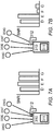
- Figures 7A and 7A show a GPS device 310 according to an exemplary embodiment of the present invention at two different attenuation states.
- Figures 7A and 7B show a GPS device 310 that includes a GPS receiver 311 and an attenuation device 312.
- a controller is not shown, but could either be part of the GPS device 310 or remote from it.
- Figures 7A and 7B show SNR values from four example satellites 300D, 300E, 300F and 300G.
- the attenuation device 312 comprises a piece of material that covers a portion of the GPS receiver 311 that attenuates the radio waves at the frequencies of the satellite signals.
- the attenuation device 312 of this embodiment is capable of altering is attenuation to have a first state in which the attenuation device 312 does not attenuate GPS satellite signals, and a second state in which the attenuation device 312 attenuates GPS satellite signals such that when a particular GPS satellite is located in a particular portion of sky the GPS satellite signals received by the GPS receiver 211 from that particular GPS satellite are attenuated (i.e. reduced or blocked).
- Figure 7A shows the attenuation device 312 in the first state (no attenuation). Hence the SNR values for the four example satellites 300D, 300E, 300F and 300G are all high.
- Figure 7B shows the attenuation device 312 in the second state (attenuation). It is clear from Figure 7B , that in this state, the attenuation device 312 is blocking the GPS signals for satellites 300F, 300G, but is not blocking satellites 300D, 300E. Hence, the SNR values for satellites 300F, 300G are lower than for satellites 300D, 300E.
- the GPS device 310 can determine its orientation quickly and easily by switching the state of the attenuation device 312 from the first state (no attenuation) to the second state (attenuation). This can be done by observing the GPS signals in the first state (i.e. angle information, azimuth information, and signal strength for each of the plurality of GPS satellites), and then observing the change in the second state. In other words, the GPS device 310 can determine the actual tilt and/or compass orientation of the GPS device 310 without pre-stored GPS information.
- the tilt and/or compass orientation of the GPS device 310 can be determined by considering the angle information and azimuth information of the "missing" GPS satellites (i.e. lower than expected SNR values) in the second state.
- the switching from the first state to the second state can be done quickly.
- the GPS device 310 could take a first reading of GPS signals in the first state and then immediately take a second reading of GPS signals in the second state.
- this method of determining orientation of the GPS device 310 does not require any pre-calibration steps.
- magnetic compasses can be used to provide orientation data in a large number of conventional scenarios.
- Many mobile devices e.g. tablets, smart phones
- compasses that comprise magnetic sensors such as a Hall sensor, Anisotropic Magnetoresistive (AMR) or Giant Magnetoresistive (GMR) sensors.
- AMR Anisotropic Magnetoresistive
- GMR Giant Magnetoresistive
- circuitry on the senor chip detects the magnetic field strength and makes the field and its direction available as digital data.
- the CPU on the mobile deice pulls this data whenever compass data is required.
- such conventional sensors acting as a compass in a mobile device require calibration. Such calibration often requires the user to perform a figure of eight motion.
- a mobile device having such a GPS device 310 need not have a separate compass sensor. This may reduce the BOM for the mobile device.
- a GPS device 310 may be used to provide initial orientation data to quicken or eliminate the calibration steps for a traditional compass sensor.
- a mobile device e.g. a smartphone, tablet or otherwise
- a positioning system according to embodiments of the invention in order to provide tilt and/or compass information.
- the tilt and/or compass information could be provided in addition to location information.
- a positioning system can provide extra functionality with little extra cost.
- the positioning system can provide a check regarding the correct working of the compass or can provide the calibration procedure which makes it easier for the user (e.g. the user does not need to walk a big 8 pattern to calibrate the compass).
- GPS device 310 as discussed above to determine orientation can be used in place of a traditional compass (i.e. one using a magnetized needle) in areas of high magnetic fields.
- the attenuation device 312 having a first state (no attenuation) and a second state (attenuation) can be implemented in various ways.
- waveguides are associated with a cut-off frequency Fc, which is the operating frequency below which attenuation occurs and above which propagation lakes place. This means a waveguide can pass frequencies which relate to the size of the waveguide. The same principle hold for gauzes or wire meshes.
- the cut-off frequency Fc of a gauze 60 can be altered by making the gauze size smaller. This can be done by adding switching elements 65 with small wires as depicted in Figure 9A . Hence, the gauze size can be smaller electronically, resulting in a changed Fc (from Fc 1 to Fc 2 as shown in Figure 9B ). Therefore, GPS signals can be attenuated if the appropriate gauze is chosen.
- many diodes are used that are put in conducting mode.
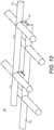
- two gauzes 71, 72 are placed close together and on top of each other to form the electronically switchable gauze 70.
- RF switch diodes 75 are connected between the two gauzes 71, 72.
- the gauses 71, 72 could be made from any conducting material (e.g. copper, aluminum, gold etc.).
- switchable gauze 70 By applying one or more sections of switchable gauze 70 to GPS device 310 (e.g. on a portion of the housing) it is possible to switch on and switch off a part of the sky concerning GPS signals, hence realizing an attenuation device 312 having a first state (no attenuation) and a second state (attenuation).
- GPS frequency range RF switching Other elements/materials resulting in GPS frequency range RF switching are also usable. For instance material which can realize a RF-conducting state in the GPS frequency range based on temperature, pressure or ultrasonic signals should not be excluded. This includes creating contacts or shortcuts between points based on locally heating up material (pieces touch because conducting material expand or contract).
- Embodiments of the invention can be used in an outdoor lighting system.
- An outdoor lighting system employing a positioning system such as those discussed above will now be described in relation to Figures 11A and 11B .
- the roadmap for outdoor street lighting is towards GPS based Mesh network and/or GPRS/3G/4G enabled fixtures that are equipped with a GPS receiver.
- the outdoor lighting system comprises a number of outdoor lighting apparatuses 400A (shown as circles).
- Each outdoor lighting apparatus 400A comprises a lighting unit 400B that includes a GPS device 410 and one or more lights 401.
- each outdoor lighting apparatus 400A comprises a pole 402 on which the lighting unit 400B is mounted.
- each GPS device 410 has a GPS receiver 411 and an attenuation device 412.
- Each GPS device 410 is connected to a server 440 that comprises a controller 420 and a storage 430.
- the GPS devices 410 and the server 440 can communicate via an appropriate network such as the internet, e.g. via GPRS/3G/4G.
- the antenna of the GPS receiver 411 can be fixed to maintain the initial relative position to the housing (not shown) of the GSP receiver 410 in the manufacturing process.
- the orientation of the GPS receiver 410 can provide information regarding the orientation of the outdoor lighting apparatuses 400A if the housing can be arranged to be always in the same position in the fixture, e.g. by fixing it with a socket based on the NEMA 3 pin (ANSI C136.10).
- any sockets or fitting connections which can only be positioned in one way may be used instead of the socket based on the NEMA 3 pin.
- the server 440 communicates with multiple GPS devices 410 via the internet.
- Each GPS device 410 comprises a RFIC (Radio Frequency Integrated Circuit) front end and a baseband processor, as is standard in the industry.
- the RFIC front end receives, demodulates and amplifies the L-band radio signal received from the multiplicity of satellites.
- the baseband processor a microprocessor installed within the GPS receiver 411, computes 3-dimensional position and velocity of the receiver and time, based on the signals broadcast by the satellites.
- the baseband processor stores map files of local area in the memory.
- the data is transmitted to the server 440 which can be a PC or a mobile device using the NMEA protocol, the standard format of GPS data.
- a communication unit (not shown) of the server 440 receives and stores the signal data and transmits it to a controller 420 of the server 440.
- the baseband processor may be located outside the GPS receiver 411 but near the RFIC front-end within the street lighting unit.
- the baseband processor may be located directly at the server 420 to take advantage of more powerful processing that that of a microprocessor.
- the GPS receiver 411 may also connect to the server 420 which can hold more detailed maps instead of storing map files in the memory of the baseband processor.
- the outdoor lighting apparatuses 400A When the outdoor lighting apparatuses 400A are installed, they may be installed in no particular order. Once installed, the GPS location of the outdoor lighting apparatus 400A may be used to identify it - as it can be assumed that the outdoor lighting apparatus 400A once installed is fixed. In other words, GPS location enables the server 440 to identify a particular outdoor lighting apparatus 400A among the plurality of the outdoor lighting apparatuses 400A.
- location specific information of multiple street outdoor lighting apparatuses 400A can be monitored and managed in real time from a remote location at the server 440.
- Each street outdoor lighting apparatus 400A may be uniquely identified in location.
- Real-time and remote monitoring may improve flexibility and visibility over individual lighting units, efficiency of energy use and level of maintenance.
- Performance history can be stored, analyzed, and visualized on the remote server 440.
- Such monitoring system can be integrated with other systems in a building or a city via public mobile communications network. For example, one central system of a city can have full control over decision on its lighting and dimming levels, setting schedules, analytics, energy consumption, and whether to repair a specific outdoor lighting apparatus 400A.
- a positioning system including a GPS device 410 including an attenuation device 412 arranged to attenuate GPS satellite signals can provide a number of important benefits.
- the GPS device 410 including an attenuation device 412 can be used as a tilt/orientation sensor without any extra material.
- the server 440 determine based on difference in attenuated GPS signals between two GPS devices 410 on the same pole.
- one pole 402 could have mounted thereon two outdoor lighting apparatuses 400A, each with a GPS device 410 with an attenuation device 412.
- the attenuation devices 412 of the two outdoor lighting apparatuses 400A were not identically arranged (if for example the attenuation devices 412 comprised a piece of conductive material placed over the GPS receiver 411 at a random orientation)
- the two outdoor lighting apparatuses 400A could be distinguished at the server 420 (and therefore be identified) based on the difference in received GPS signals.
- the actual orientation of the attenuation devices 412 would not matter in this instance, as the server 420 would only need to tell one GPS receiver 411 from another.
- the two outdoor lighting apparatuses could be distinguished at the server 420 (and therefore be identified) based on the difference in received GPS signal.
- the location of a first outdoor light apparatus 400A may be distinguished from the location of a second outdoor light apparatus 400A on the basis of a difference in received GPS signals from the first outdoor light apparatus 400A and the second outdoor light apparatus 400A.
- a difference in SNR for a particular satellite measured at the second outdoor light apparatus when compared to the first outdoor light apparatus 400A would enable the GPS signals from the first outdoor light apparatus 400A to be differentiated from the second outdoor light apparatus 400A.
- the first outdoor light apparatus 400A and the second outdoor light apparatus 400A could be individually identified by the controller 420, even if their GPS receivers 411 were close enough that a conventional GPS location reading would give the same result.
- such embodiments enable a controller to identify two outdoor light apparatuses on the same pole using only the GPS receivers 411.
- embodiments of the invention help to accurately determine the position and orientation of luminaires on a pole, especially when the pole comprises multiple luminaires (e.g. one oriented for street lighting and another for bicycle or footpad lighting).
- the pole comprises multiple luminaires (e.g. one oriented for street lighting and another for bicycle or footpad lighting).
- conventional GPS receivers embedded in the luminaire do not allow distinguishing between the two.
- the sky may be made unique for every angle and/or rotation of the outdoor lighting apparatus 400A.
- the housing can be arranged to be always in the same position in the outdoor lighting apparatus 400A, e.g. by fixing it with a socket based on the NEMA 3 pin, then GPS receiver 410 is always in the same position with respect to the socket in the outdoor lighting apparatus 400A, and change over time in the "sky map" (see Figures 2A-D ) can be used to determine angle and orientation.
- the antenna may be covered with material which attenuates incoming signals under a certain angle. It is also possible to completely block signals under a certain angle by applying small pieces of metal instead of attenuating material. This can be done in the manufacturing process of the outdoor lighting apparatuses 400A (in case the GPS receiver is inside the outdoor lighting apparatus 400A) or in the cabinet attached to the fixture of the outdoor lighting apparatus 400A.
- the positioning system can not only detect change in the sky-line seen from every GPS receiver but also detect a wrong mounting of hanging fixture (e.g. an outdoor lighting apparatus), or the absolute azimuth and angle of a fixture from day one after installation, so within approximately half an hour.
- a wrong mounting of hanging fixture e.g. an outdoor lighting apparatus
- the positioning system can be done by the positioning system comparing the (calculated) and known sky-map as seen from the fixture with the measured sky-map.
- the "measured sky-map” in this case refers to the sky-map determined using received satellite signals.
- the positioning system can detect which satellite signals disappear and become visible due to the blocking / attenuation of buildings/trees etc. in its surroundings. If the known sky line can be mapped within a certain percentage of coverage after rotation and tilting, then the positioning system can determine the azimuth and angle of that particular fixture. It the position of the fixture is not known within a couple of meters but more, calculations can be made trying to map this measured and known sky-map from a couple of locations in that surrounding.
- examples may provide a computer-implemented method of positioning system comprising: using a GPS device including a GPS receiver to receive GPS satellite signals from a plurality of GPS satellites, and using an attenuation device to attenuate GPS satellite signals such that when a GPS satellite is located in a first portion of sky the GPS satellite signals received by the GPS receiver from said GPS satellite are attenuated; and determining position information of the GPS device based on received GPS information from the GPS device.
- a computer readable medium carrying computer readable code for controlling a computer to carry out the method of any one of the above aspects may be also provided.
- Examples of positioning systems may comprise: a GPS device including a GPS receiver arranged to receive GPS satellite signals from a plurality of GPS satellites and an attenuation device arranged to attenuate GPS satellite signals such that when a GPS satellite is located in a first portion of sky the GPS satellite signals received by the GPS receiver from said GPS satellite are attenuated; a storage arranged to store satellite location information for the plurality of GPS satellites over time at a location of the GPS receiver; and a controller arranged to determine location information of the GPS device based on received GPS information from the GPS device, wherein the received GPS information comprises information on signal strengths of the GPS satellite signals received by the GPS receiver, wherein if a signal strength for a first GPS satellite is lower than a threshold signal strength at a point in time then the controller is arranged to determine that the first GPS satellite is in the first portion of the sky and determine angle information of the GPS device relative to earth's normal and/or orientation information of the GPS device in a horizontal plane using the stored satellite location information.
- a GPS device including a GPS
Landscapes
- Engineering & Computer Science (AREA)
- Radar, Positioning & Navigation (AREA)
- Remote Sensing (AREA)
- Physics & Mathematics (AREA)
- General Physics & Mathematics (AREA)
- Computer Networks & Wireless Communication (AREA)
- Position Fixing By Use Of Radio Waves (AREA)
Claims (15)
- Système de positionnement (100, 200) comprenant :un dispositif GPS (110, 210) incluant un récepteur GPS (111, 211) agencé pour recevoir des signaux de satellite GPS depuis une pluralité de satellites GPS (300A..300H) ; etun dispositif de commande (120, 220) agencé pour déterminer des informations de localisation du dispositif GPS sur la base des informations GPS reçues du dispositif GPS, dans lequel les informations GPS reçues comprennent des informations sur des intensités de signal des signaux de satellite GPS reçus par le récepteur GPS,caractérisé en ce que le système de positionnement comprend :un stockage (230) agencé pour stocker des informations de localisation de satellite pour la pluralité de satellites GPS au cours du temps à un emplacement du récepteur GPS, les informations de satellite comprenant des informations d'angle de référence, des informations d'azimut de référence, et une intensité de signal de référence, sous une forme non atténuée par le dispositif d'atténuation, pour la pluralité de satellites GPS au cours du temps à l'emplacement du récepteur GPS ;le dispositif GPS inclut un dispositif d'atténuation (112, 212) agencé pour atténuer des signaux de satellite GPS de telle sorte que lorsqu'un satellite GPS est situé dans une première partie (AA) du ciel, les signaux de satellite GPS reçus par le récepteur GPS en provenance dudit satellite GPS sont atténués, le dispositif d'atténuation restituant un diagramme de rayonnement d'antenne asymétrique pour le récepteur GPS ; etdans lequel, si une intensité de signal pour un premier satellite GPS est inférieure à une intensité de signal de seuil à un moment dans le temps, le dispositif de commande est alors agencé pour déterminer que le premier satellite GPS se trouve dans la première partie du ciel et déterminer des informations d'angle du dispositif GPS par rapport à des informations d'orientation normale et/ou par boussole du dispositif GPS dans un plan horizontal en utilisant les informations d'angle de référence et les informations d'azimut de référence pour le premier satellite GPS et une connaissance de la première partie du ciel atténuée par le dispositif d'atténuation.
- Système de positionnement selon la revendication 1, dans lequel le dispositif d'atténuation est agencé pour atténuer des signaux de satellite GPS en empêchant des signaux de satellite GPS provenant de satellites GPS situés dans la première partie du ciel d'être reçus par le récepteur GPS.
- Système de positionnement selon l'une quelconque des revendications précédentes, dans lequel le dispositif d'atténuation comprend une partie de matériau d'atténuation de signal de satellite GPS située entre le récepteur GPS et le ciel.
- Système de positionnement selon l'une quelconque des revendications précédentes, dans lequel le dispositif d'atténuation comprend une partie de matériau de réflexion de signal de satellite GPS située sous le récepteur GPS.
- Système de positionnement selon l'une quelconque des revendications précédentes, dans lequel le dispositif d'atténuation est fixé en position par rapport au récepteur GPS.
- Système de positionnement selon la revendication 5, dans lequel les informations d'angle de référence, les informations d'azimut de référence, et l'intensité de signal de référence correspondent à des signaux de satellite GPS provenant de la pluralité de satellites GPS non atténués par le dispositif d'atténuation ;dans lequel le dispositif de commande est agencé pour recevoir des informations d'angle, des informations d'azimut, et une intensité de signal pour chacun de la pluralité de satellites GPS provenant du récepteur GPS ;dans lequel le dispositif de commande est agencé pour comparer l'intensité de signal reçu avec l'intensité de signal de référence pour chacun de la pluralité de satellites GPS ; etdans lequel si l'intensité de signal reçu pour le premier satellite GPS est inférieure à l'intensité de signal de référence pour le premier satellite GPS, alors le dispositif de commande est agencé pour déterminer que le premier satellite GPS se trouve dans la première partie du.
- Système de positionnement selon l'une quelconque des revendications précédentes, dans lequel le dispositif de commande est agencé pour déterminer un changement de l'angle du dispositif GPS par rapport à la normale à la terre et/ou un changement de l'orientation du dispositif GPS dans un plan horizontal sur la base d'un changement d'une intensité de signal d'au moins un signal de satellite GPS reçu.
- Système de positionnement selon l'une quelconque des revendications précédentes,dans lequel le dispositif de commande est agencé pour déterminer une heure de la journée à laquelle des signaux de satellite GPS reçus provenant d'un satellite GPS deviennent atténués en résultat du passage dudit satellite GPS à travers la première partie du ciel ;dans lequel le dispositif de commande est agencé pour déterminer un changement d'orientation du dispositif GPS sur la base d'un changement de l'heure de la journée à laquelle les signaux de satellite GPS reçus provenant dudit satellite GPS deviennent atténués.
- Système de positionnement selon l'une quelconque des revendications précédentes, dans lequel le dispositif d'atténuation présente un premier état dans lequel le dispositif d'atténuation n'atténue pas de signaux de satellite GPS, et un second état dans lequel le dispositif d'atténuation atténue des signaux de satellite GPS provenant de la première partie du ciel.
- Système de positionnement selon la revendication 9, dans lequel le dispositif d'atténuation comprend un premier grillage (71), un second grillage (72) sur le dessus du premier grillage, dans lequel le premier grillage et le second grillage ne sont pas connectés électriquement dans le premier état, et dans lequel le premier grillage et le second grillage sont connectés électriquement le premier grillage et second grillage dans le second état.
- Système de positionnement selon la revendication 10, dans lequel le dispositif d'atténuation comprend au moins une diode de commutation (75) connectée entre le premier grillage et le second grillage, dans lequel la au moins une diode de commutation est agencée pour connecter électriquement le premier grillage et le second grillage dans le second état.
- Dispositif mobile comprenant :
un système de positionnement selon l'une quelconque des revendications 1 à 11. - Système d'éclairage extérieur comprenant :un système de positionnement selon l'une quelconque des revendications 1 à 11 ;un appareil d'éclairage extérieur (400A) comprenant une unité d'éclairage (400B) incluant le dispositif GPS (410) et une ou plusieurs lumières (401) ;dans lequel le dispositif de commande est agencé pour déterminer des informations d'emplacement de l'unité d'éclairage sur la base des informations GPS reçues provenant du dispositif GPS.
- Système d'éclairage extérieur selon la revendication 13, dans lequel l'appareil d'éclairage extérieur comprend en outre :une seconde unité d'éclairage incluant un second dispositif GPS et une ou plusieurs secondes lumières ;dans lequel le second dispositif GPS inclut un second récepteur GPS agencé pour recevoir des signaux de satellite GPS provenant de la pluralité de satellites GPS ;dans lequel le dispositif de commande est agencé pour déterminer des informations d'emplacement de la seconde unité d'éclairage sur la base d'informations GPS reçues provenant du second dispositif GPS.
- Système d'éclairage extérieur selon la revendication 14, dans lequel le second dispositif GPS inclut en outre un second dispositif d'atténuation agencé pour atténuer des signaux de satellite GPS de telle sorte que lorsqu'un satellite GPS est situé dans une seconde partie du ciel, les signaux de satellite GPS reçus par le second récepteur GPS pour ledit satellite GPS sont atténués.
Applications Claiming Priority (1)
| Application Number | Priority Date | Filing Date | Title |
|---|---|---|---|
| EP16193278 | 2016-10-11 |
Publications (2)
| Publication Number | Publication Date |
|---|---|
| EP3309587A1 EP3309587A1 (fr) | 2018-04-18 |
| EP3309587B1 true EP3309587B1 (fr) | 2021-12-08 |
Family
ID=57123908
Family Applications (1)
| Application Number | Title | Priority Date | Filing Date |
|---|---|---|---|
| EP17195463.9A Active EP3309587B1 (fr) | 2016-10-11 | 2017-10-09 | Système et procédé de positionnement |
Country Status (5)
| Country | Link |
|---|---|
| US (1) | US10935666B2 (fr) |
| EP (1) | EP3309587B1 (fr) |
| CN (1) | CN109844567B (fr) |
| ES (1) | ES2906652T3 (fr) |
| WO (1) | WO2018069239A1 (fr) |
Families Citing this family (5)
| Publication number | Priority date | Publication date | Assignee | Title |
|---|---|---|---|---|
| CN112543071B (zh) * | 2020-11-06 | 2022-11-08 | 重庆电子工程职业学院 | 一种具有定位功能的信号强度接收机及其实施方法 |
| CN114326431B (zh) * | 2022-03-15 | 2023-01-24 | 云丁网络技术(北京)有限公司 | 一种智能门的控制系统、方法、装置及存储介质 |
| US12395237B2 (en) | 2022-07-18 | 2025-08-19 | Qualcomm Incorporated | Assistance data for orienting a mobile device for satellite-based communications |
| US12493124B2 (en) | 2022-08-08 | 2025-12-09 | Qualcomm Incorporated | Satellite positioning for satellite-based communications |
| US12445192B2 (en) | 2022-08-19 | 2025-10-14 | Qualcomm Incorporated | Mobile device orientation guidance for satellite-based communications |
Family Cites Families (20)
| Publication number | Priority date | Publication date | Assignee | Title |
|---|---|---|---|---|
| US5815114A (en) * | 1996-04-05 | 1998-09-29 | Discovision Associates | Positioning system and method |
| US6313786B1 (en) * | 1998-07-02 | 2001-11-06 | Snaptrack, Inc. | Method and apparatus for measurement processing of satellite positioning system (SPS) signals |
| US20030142036A1 (en) * | 2001-02-08 | 2003-07-31 | Wilhelm Michael John | Multiband or broadband frequency selective surface |
| AU2003240168A1 (en) | 2003-06-10 | 2005-01-04 | Nokia Corporation | Reception of signals in a device comprising a transmitter |
| EP1729145B1 (fr) * | 2005-06-02 | 2013-08-07 | GMV Aerospace and Defence S.A. | Procédé et système permettant de fournir la solution de position GNSS avec une intégrité garantie dans un environnement non contrôlé |
| US7898474B2 (en) * | 2006-07-20 | 2011-03-01 | Seiko Epson Corporation | Positioning device, method of controlling positioning device, and recording medium having program for controlling positioning device recorded thereon |
| JP4285509B2 (ja) * | 2006-07-20 | 2009-06-24 | セイコーエプソン株式会社 | 測位装置、測位装置の制御方法及びプログラム |
| TW200905119A (en) * | 2007-07-30 | 2009-02-01 | Topco Technologies Corp | Illumination system |
| JP2010203959A (ja) * | 2009-03-04 | 2010-09-16 | Seiko Epson Corp | 初期位置決定方法、位置算出方法及び位置算出装置 |
| US8521412B2 (en) * | 2010-03-26 | 2013-08-27 | Honda Motor Co., Ltd. | Method of determining absolute position for a motor vehicle |
| CN102223706A (zh) * | 2010-04-15 | 2011-10-19 | 上海启电信息科技有限公司 | 一种移动定位服务系统 |
| CN101860793A (zh) * | 2010-05-18 | 2010-10-13 | 九福科技顾问股份有限公司 | 地理感知电子装置及其服务系统 |
| US8645060B2 (en) * | 2010-09-07 | 2014-02-04 | Qualcomm Incorporated | Positioning network availability and reliability based routing |
| CN102955162A (zh) | 2011-08-16 | 2013-03-06 | 神基科技股份有限公司 | 卫星定位方法 |
| JP6175775B2 (ja) * | 2013-01-18 | 2017-08-09 | セイコーエプソン株式会社 | タイミング信号生成装置、電子機器及び移動体 |
| US20140249771A1 (en) * | 2013-03-01 | 2014-09-04 | Xue Yang | Location estimation using a mobile device |
| US20150347351A1 (en) * | 2014-05-30 | 2015-12-03 | Apple Inc. | Determining Location System Signal Quality |
| US11852741B2 (en) | 2014-09-29 | 2023-12-26 | Telecom Italia S.P.A. | Positioning method and system for wireless communication networks |
| CN105792124B (zh) * | 2014-12-26 | 2020-10-13 | 腾讯科技(深圳)有限公司 | 定位方法和装置 |
| JP6865521B2 (ja) * | 2015-07-02 | 2021-04-28 | 株式会社トプコン | 航法信号処理装置、航法信号処理方法および航法信号処理用プログラム |
-
2017
- 2017-10-09 WO PCT/EP2017/075660 patent/WO2018069239A1/fr not_active Ceased
- 2017-10-09 ES ES17195463T patent/ES2906652T3/es active Active
- 2017-10-09 CN CN201780062728.9A patent/CN109844567B/zh active Active
- 2017-10-09 EP EP17195463.9A patent/EP3309587B1/fr active Active
- 2017-10-11 US US15/730,144 patent/US10935666B2/en active Active
Non-Patent Citations (1)
| Title |
|---|
| None * |
Also Published As
| Publication number | Publication date |
|---|---|
| WO2018069239A1 (fr) | 2018-04-19 |
| CN109844567A (zh) | 2019-06-04 |
| US10935666B2 (en) | 2021-03-02 |
| ES2906652T3 (es) | 2022-04-19 |
| US20180100932A1 (en) | 2018-04-12 |
| WO2018069239A9 (fr) | 2019-02-28 |
| EP3309587A1 (fr) | 2018-04-18 |
| CN109844567B (zh) | 2023-06-09 |
Similar Documents
| Publication | Publication Date | Title |
|---|---|---|
| EP3309587B1 (fr) | Système et procédé de positionnement | |
| US10670766B2 (en) | Utility locating systems, devices, and methods using radio broadcast signals | |
| US11156737B1 (en) | Buried object locator apparatus and methods | |
| US11796707B1 (en) | User interfaces for utility locators | |
| US9360310B2 (en) | Multi-sensor indoor localization method and device based on light intensity | |
| EP3017317B1 (fr) | Procédé de détermination d'orientation | |
| CN104662442B (zh) | 用于检测杆的物理变形的系统和方法 | |
| US20130135146A1 (en) | Method for directed antenna alignment through augmented reality | |
| CN104391273B (zh) | 一种基于圆形投影的可见光定位方法及系统 | |
| CN107607109A (zh) | 一种基于双磁信标的空间定位方法、装置及系统 | |
| US12360251B2 (en) | GNSS positioning methods and devices using PPP-RTK, RTK, SSR, or like correction data | |
| US20130088725A1 (en) | Positioning method and positioning system based on light intensity | |
| US10530051B2 (en) | Antenna alignment device and methods for aligning antennas | |
| CN107340530A (zh) | 一种基于rtk的分体式gnss真北定向装置 | |
| US11988755B1 (en) | Utility locating devices employing multiple spaced apart GNSS antennas | |
| CN109828246A (zh) | 调试安防雷达标定和用户地安装标定的方法 | |
| US20230112451A1 (en) | Antenna alignment apparatus | |
| TWM530957U (zh) | 室內定位裝置 | |
| US12216215B2 (en) | Antenna alignment apparatus | |
| CA2966083A1 (fr) | Appareil d'alignement d'antennes et methodes d'alignement d'antennes | |
| EP3295213B1 (fr) | Amélioration de l'exactitude spatiale de positions mesurées par les récepteurs d'un système de satellites de navigation globale placés dans une configuration spatiale | |
| KR101923599B1 (ko) | 이동체의 실내 위치 인식 시스템 및 방법 | |
| CN103913759A (zh) | 一种防盗定位追踪系统 | |
| JP2014096763A (ja) | 測定装置 | |
| KR101600830B1 (ko) | 센서를 이용한 기지국 안테나 지향각 정보 제공 장치 및 이를 포함하는 기지국 안테나 |
Legal Events
| Date | Code | Title | Description |
|---|---|---|---|
| PUAI | Public reference made under article 153(3) epc to a published international application that has entered the european phase |
Free format text: ORIGINAL CODE: 0009012 |
|
| STAA | Information on the status of an ep patent application or granted ep patent |
Free format text: STATUS: THE APPLICATION HAS BEEN PUBLISHED |
|
| AK | Designated contracting states |
Kind code of ref document: A1 Designated state(s): AL AT BE BG CH CY CZ DE DK EE ES FI FR GB GR HR HU IE IS IT LI LT LU LV MC MK MT NL NO PL PT RO RS SE SI SK SM TR |
|
| AX | Request for extension of the european patent |
Extension state: BA ME |
|
| STAA | Information on the status of an ep patent application or granted ep patent |
Free format text: STATUS: REQUEST FOR EXAMINATION WAS MADE |
|
| 17P | Request for examination filed |
Effective date: 20181018 |
|
| RBV | Designated contracting states (corrected) |
Designated state(s): AL AT BE BG CH CY CZ DE DK EE ES FI FR GB GR HR HU IE IS IT LI LT LU LV MC MK MT NL NO PL PT RO RS SE SI SK SM TR |
|
| RAP1 | Party data changed (applicant data changed or rights of an application transferred) |
Owner name: PHILIPS LIGHTING HOLDING B.V. |
|
| RAP1 | Party data changed (applicant data changed or rights of an application transferred) |
Owner name: SIGNIFY HOLDING B.V. |
|
| STAA | Information on the status of an ep patent application or granted ep patent |
Free format text: STATUS: EXAMINATION IS IN PROGRESS |
|
| 17Q | First examination report despatched |
Effective date: 20200212 |
|
| GRAP | Despatch of communication of intention to grant a patent |
Free format text: ORIGINAL CODE: EPIDOSNIGR1 |
|
| STAA | Information on the status of an ep patent application or granted ep patent |
Free format text: STATUS: GRANT OF PATENT IS INTENDED |
|
| INTG | Intention to grant announced |
Effective date: 20210115 |
|
| GRAJ | Information related to disapproval of communication of intention to grant by the applicant or resumption of examination proceedings by the epo deleted |
Free format text: ORIGINAL CODE: EPIDOSDIGR1 |
|
| STAA | Information on the status of an ep patent application or granted ep patent |
Free format text: STATUS: EXAMINATION IS IN PROGRESS |
|
| GRAP | Despatch of communication of intention to grant a patent |
Free format text: ORIGINAL CODE: EPIDOSNIGR1 |
|
| STAA | Information on the status of an ep patent application or granted ep patent |
Free format text: STATUS: GRANT OF PATENT IS INTENDED |
|
| INTC | Intention to grant announced (deleted) | ||
| INTG | Intention to grant announced |
Effective date: 20210514 |
|
| RIN1 | Information on inventor provided before grant (corrected) |
Inventor name: DAMINK, PAULUS HENRICUS ANTONIUS Inventor name: DRAAIJER, MAURICE HERMAN JOHAN |
|
| GRAS | Grant fee paid |
Free format text: ORIGINAL CODE: EPIDOSNIGR3 |
|
| GRAA | (expected) grant |
Free format text: ORIGINAL CODE: 0009210 |
|
| STAA | Information on the status of an ep patent application or granted ep patent |
Free format text: STATUS: THE PATENT HAS BEEN GRANTED |
|
| AK | Designated contracting states |
Kind code of ref document: B1 Designated state(s): AL AT BE BG CH CY CZ DE DK EE ES FI FR GB GR HR HU IE IS IT LI LT LU LV MC MK MT NL NO PL PT RO RS SE SI SK SM TR |
|
| REG | Reference to a national code |
Ref country code: GB Ref legal event code: FG4D |
|
| REG | Reference to a national code |
Ref country code: AT Ref legal event code: REF Ref document number: 1454189 Country of ref document: AT Kind code of ref document: T Effective date: 20211215 Ref country code: CH Ref legal event code: EP |
|
| REG | Reference to a national code |
Ref country code: DE Ref legal event code: R096 Ref document number: 602017050510 Country of ref document: DE |
|
| REG | Reference to a national code |
Ref country code: IE Ref legal event code: FG4D |
|
| REG | Reference to a national code |
Ref country code: NL Ref legal event code: FP |
|
| REG | Reference to a national code |
Ref country code: SE Ref legal event code: TRGR |
|
| REG | Reference to a national code |
Ref country code: LT Ref legal event code: MG9D |
|
| REG | Reference to a national code |
Ref country code: ES Ref legal event code: FG2A Ref document number: 2906652 Country of ref document: ES Kind code of ref document: T3 Effective date: 20220419 |
|
| PG25 | Lapsed in a contracting state [announced via postgrant information from national office to epo] |
Ref country code: RS Free format text: LAPSE BECAUSE OF FAILURE TO SUBMIT A TRANSLATION OF THE DESCRIPTION OR TO PAY THE FEE WITHIN THE PRESCRIBED TIME-LIMIT Effective date: 20211208 Ref country code: LT Free format text: LAPSE BECAUSE OF FAILURE TO SUBMIT A TRANSLATION OF THE DESCRIPTION OR TO PAY THE FEE WITHIN THE PRESCRIBED TIME-LIMIT Effective date: 20211208 Ref country code: FI Free format text: LAPSE BECAUSE OF FAILURE TO SUBMIT A TRANSLATION OF THE DESCRIPTION OR TO PAY THE FEE WITHIN THE PRESCRIBED TIME-LIMIT Effective date: 20211208 Ref country code: BG Free format text: LAPSE BECAUSE OF FAILURE TO SUBMIT A TRANSLATION OF THE DESCRIPTION OR TO PAY THE FEE WITHIN THE PRESCRIBED TIME-LIMIT Effective date: 20220308 |
|
| REG | Reference to a national code |
Ref country code: AT Ref legal event code: MK05 Ref document number: 1454189 Country of ref document: AT Kind code of ref document: T Effective date: 20211208 |
|
| PG25 | Lapsed in a contracting state [announced via postgrant information from national office to epo] |
Ref country code: NO Free format text: LAPSE BECAUSE OF FAILURE TO SUBMIT A TRANSLATION OF THE DESCRIPTION OR TO PAY THE FEE WITHIN THE PRESCRIBED TIME-LIMIT Effective date: 20220308 Ref country code: LV Free format text: LAPSE BECAUSE OF FAILURE TO SUBMIT A TRANSLATION OF THE DESCRIPTION OR TO PAY THE FEE WITHIN THE PRESCRIBED TIME-LIMIT Effective date: 20211208 Ref country code: HR Free format text: LAPSE BECAUSE OF FAILURE TO SUBMIT A TRANSLATION OF THE DESCRIPTION OR TO PAY THE FEE WITHIN THE PRESCRIBED TIME-LIMIT Effective date: 20211208 Ref country code: GR Free format text: LAPSE BECAUSE OF FAILURE TO SUBMIT A TRANSLATION OF THE DESCRIPTION OR TO PAY THE FEE WITHIN THE PRESCRIBED TIME-LIMIT Effective date: 20220309 |
|
| PG25 | Lapsed in a contracting state [announced via postgrant information from national office to epo] |
Ref country code: SM Free format text: LAPSE BECAUSE OF FAILURE TO SUBMIT A TRANSLATION OF THE DESCRIPTION OR TO PAY THE FEE WITHIN THE PRESCRIBED TIME-LIMIT Effective date: 20211208 Ref country code: SK Free format text: LAPSE BECAUSE OF FAILURE TO SUBMIT A TRANSLATION OF THE DESCRIPTION OR TO PAY THE FEE WITHIN THE PRESCRIBED TIME-LIMIT Effective date: 20211208 Ref country code: RO Free format text: LAPSE BECAUSE OF FAILURE TO SUBMIT A TRANSLATION OF THE DESCRIPTION OR TO PAY THE FEE WITHIN THE PRESCRIBED TIME-LIMIT Effective date: 20211208 Ref country code: PT Free format text: LAPSE BECAUSE OF FAILURE TO SUBMIT A TRANSLATION OF THE DESCRIPTION OR TO PAY THE FEE WITHIN THE PRESCRIBED TIME-LIMIT Effective date: 20220408 Ref country code: EE Free format text: LAPSE BECAUSE OF FAILURE TO SUBMIT A TRANSLATION OF THE DESCRIPTION OR TO PAY THE FEE WITHIN THE PRESCRIBED TIME-LIMIT Effective date: 20211208 Ref country code: CZ Free format text: LAPSE BECAUSE OF FAILURE TO SUBMIT A TRANSLATION OF THE DESCRIPTION OR TO PAY THE FEE WITHIN THE PRESCRIBED TIME-LIMIT Effective date: 20211208 |
|
| PG25 | Lapsed in a contracting state [announced via postgrant information from national office to epo] |
Ref country code: PL Free format text: LAPSE BECAUSE OF FAILURE TO SUBMIT A TRANSLATION OF THE DESCRIPTION OR TO PAY THE FEE WITHIN THE PRESCRIBED TIME-LIMIT Effective date: 20211208 Ref country code: AT Free format text: LAPSE BECAUSE OF FAILURE TO SUBMIT A TRANSLATION OF THE DESCRIPTION OR TO PAY THE FEE WITHIN THE PRESCRIBED TIME-LIMIT Effective date: 20211208 |
|
| REG | Reference to a national code |
Ref country code: DE Ref legal event code: R097 Ref document number: 602017050510 Country of ref document: DE |
|
| PG25 | Lapsed in a contracting state [announced via postgrant information from national office to epo] |
Ref country code: IS Free format text: LAPSE BECAUSE OF FAILURE TO SUBMIT A TRANSLATION OF THE DESCRIPTION OR TO PAY THE FEE WITHIN THE PRESCRIBED TIME-LIMIT Effective date: 20220408 |
|
| PLBE | No opposition filed within time limit |
Free format text: ORIGINAL CODE: 0009261 |
|
| STAA | Information on the status of an ep patent application or granted ep patent |
Free format text: STATUS: NO OPPOSITION FILED WITHIN TIME LIMIT |
|
| PG25 | Lapsed in a contracting state [announced via postgrant information from national office to epo] |
Ref country code: DK Free format text: LAPSE BECAUSE OF FAILURE TO SUBMIT A TRANSLATION OF THE DESCRIPTION OR TO PAY THE FEE WITHIN THE PRESCRIBED TIME-LIMIT Effective date: 20211208 Ref country code: AL Free format text: LAPSE BECAUSE OF FAILURE TO SUBMIT A TRANSLATION OF THE DESCRIPTION OR TO PAY THE FEE WITHIN THE PRESCRIBED TIME-LIMIT Effective date: 20211208 |
|
| 26N | No opposition filed |
Effective date: 20220909 |
|
| PG25 | Lapsed in a contracting state [announced via postgrant information from national office to epo] |
Ref country code: SI Free format text: LAPSE BECAUSE OF FAILURE TO SUBMIT A TRANSLATION OF THE DESCRIPTION OR TO PAY THE FEE WITHIN THE PRESCRIBED TIME-LIMIT Effective date: 20211208 |
|
| PG25 | Lapsed in a contracting state [announced via postgrant information from national office to epo] |
Ref country code: MC Free format text: LAPSE BECAUSE OF FAILURE TO SUBMIT A TRANSLATION OF THE DESCRIPTION OR TO PAY THE FEE WITHIN THE PRESCRIBED TIME-LIMIT Effective date: 20211208 |
|
| REG | Reference to a national code |
Ref country code: CH Ref legal event code: PL |
|
| P01 | Opt-out of the competence of the unified patent court (upc) registered |
Effective date: 20230425 |
|
| PG25 | Lapsed in a contracting state [announced via postgrant information from national office to epo] |
Ref country code: LU Free format text: LAPSE BECAUSE OF NON-PAYMENT OF DUE FEES Effective date: 20221009 |
|
| PG25 | Lapsed in a contracting state [announced via postgrant information from national office to epo] |
Ref country code: LI Free format text: LAPSE BECAUSE OF NON-PAYMENT OF DUE FEES Effective date: 20221031 Ref country code: CH Free format text: LAPSE BECAUSE OF NON-PAYMENT OF DUE FEES Effective date: 20221031 |
|
| PG25 | Lapsed in a contracting state [announced via postgrant information from national office to epo] |
Ref country code: IE Free format text: LAPSE BECAUSE OF NON-PAYMENT OF DUE FEES Effective date: 20221009 |
|
| PG25 | Lapsed in a contracting state [announced via postgrant information from national office to epo] |
Ref country code: HU Free format text: LAPSE BECAUSE OF FAILURE TO SUBMIT A TRANSLATION OF THE DESCRIPTION OR TO PAY THE FEE WITHIN THE PRESCRIBED TIME-LIMIT; INVALID AB INITIO Effective date: 20171009 |
|
| PG25 | Lapsed in a contracting state [announced via postgrant information from national office to epo] |
Ref country code: CY Free format text: LAPSE BECAUSE OF FAILURE TO SUBMIT A TRANSLATION OF THE DESCRIPTION OR TO PAY THE FEE WITHIN THE PRESCRIBED TIME-LIMIT Effective date: 20211208 |
|
| PG25 | Lapsed in a contracting state [announced via postgrant information from national office to epo] |
Ref country code: MK Free format text: LAPSE BECAUSE OF FAILURE TO SUBMIT A TRANSLATION OF THE DESCRIPTION OR TO PAY THE FEE WITHIN THE PRESCRIBED TIME-LIMIT Effective date: 20211208 |
|
| PG25 | Lapsed in a contracting state [announced via postgrant information from national office to epo] |
Ref country code: MT Free format text: LAPSE BECAUSE OF FAILURE TO SUBMIT A TRANSLATION OF THE DESCRIPTION OR TO PAY THE FEE WITHIN THE PRESCRIBED TIME-LIMIT Effective date: 20211208 |
|
| PGFP | Annual fee paid to national office [announced via postgrant information from national office to epo] |
Ref country code: NL Payment date: 20251024 Year of fee payment: 9 |
|
| PG25 | Lapsed in a contracting state [announced via postgrant information from national office to epo] |
Ref country code: TR Free format text: LAPSE BECAUSE OF FAILURE TO SUBMIT A TRANSLATION OF THE DESCRIPTION OR TO PAY THE FEE WITHIN THE PRESCRIBED TIME-LIMIT Effective date: 20211208 |
|
| PGFP | Annual fee paid to national office [announced via postgrant information from national office to epo] |
Ref country code: GB Payment date: 20251023 Year of fee payment: 9 |
|
| PGFP | Annual fee paid to national office [announced via postgrant information from national office to epo] |
Ref country code: IT Payment date: 20251022 Year of fee payment: 9 |
|
| PGFP | Annual fee paid to national office [announced via postgrant information from national office to epo] |
Ref country code: FR Payment date: 20251027 Year of fee payment: 9 |
|
| PGFP | Annual fee paid to national office [announced via postgrant information from national office to epo] |
Ref country code: BE Payment date: 20251024 Year of fee payment: 9 |
|
| PGFP | Annual fee paid to national office [announced via postgrant information from national office to epo] |
Ref country code: SE Payment date: 20251024 Year of fee payment: 9 |
|
| PGFP | Annual fee paid to national office [announced via postgrant information from national office to epo] |
Ref country code: ES Payment date: 20251118 Year of fee payment: 9 |
|
| PGFP | Annual fee paid to national office [announced via postgrant information from national office to epo] |
Ref country code: DE Payment date: 20251229 Year of fee payment: 9 |