EP3309854A1 - Moyen d'éclairage comprenant une delo pour phare de véhicule - Google Patents
Moyen d'éclairage comprenant une delo pour phare de véhicule Download PDFInfo
- Publication number
- EP3309854A1 EP3309854A1 EP16194191.9A EP16194191A EP3309854A1 EP 3309854 A1 EP3309854 A1 EP 3309854A1 EP 16194191 A EP16194191 A EP 16194191A EP 3309854 A1 EP3309854 A1 EP 3309854A1
- Authority
- EP
- European Patent Office
- Prior art keywords
- oled
- encapsulated
- plate
- light
- plastic holder
- Prior art date
- Legal status (The legal status is an assumption and is not a legal conclusion. Google has not performed a legal analysis and makes no representation as to the accuracy of the status listed.)
- Pending
Links
- 229920003023 plastic Polymers 0.000 claims abstract description 174
- 239000004033 plastic Substances 0.000 claims abstract description 166
- 238000001228 spectrum Methods 0.000 claims abstract description 15
- 239000004065 semiconductor Substances 0.000 claims abstract description 7
- 239000011521 glass Substances 0.000 claims description 48
- 238000005538 encapsulation Methods 0.000 claims description 47
- 239000000463 material Substances 0.000 claims description 23
- 239000004020 conductor Substances 0.000 claims description 17
- 238000005516 engineering process Methods 0.000 claims description 14
- 238000000034 method Methods 0.000 abstract description 40
- 230000003287 optical effect Effects 0.000 abstract description 31
- 238000004519 manufacturing process Methods 0.000 abstract description 14
- 239000012780 transparent material Substances 0.000 abstract description 12
- 230000006870 function Effects 0.000 description 44
- 239000007788 liquid Substances 0.000 description 32
- 230000002093 peripheral effect Effects 0.000 description 21
- 239000010410 layer Substances 0.000 description 20
- 239000012044 organic layer Substances 0.000 description 16
- 230000006378 damage Effects 0.000 description 15
- 238000001816 cooling Methods 0.000 description 13
- 238000009826 distribution Methods 0.000 description 13
- 238000001746 injection moulding Methods 0.000 description 13
- 230000008901 benefit Effects 0.000 description 11
- 239000007787 solid Substances 0.000 description 11
- 238000007711 solidification Methods 0.000 description 10
- 230000008023 solidification Effects 0.000 description 10
- 239000000853 adhesive Substances 0.000 description 9
- 230000001070 adhesive effect Effects 0.000 description 9
- 239000010408 film Substances 0.000 description 8
- 239000003550 marker Substances 0.000 description 8
- 238000013461 design Methods 0.000 description 7
- 229910010272 inorganic material Inorganic materials 0.000 description 7
- 239000011147 inorganic material Substances 0.000 description 7
- 230000032683 aging Effects 0.000 description 6
- 229910052751 metal Inorganic materials 0.000 description 5
- 239000002184 metal Substances 0.000 description 5
- 230000035882 stress Effects 0.000 description 5
- 239000000126 substance Substances 0.000 description 5
- 229910052782 aluminium Inorganic materials 0.000 description 4
- 239000002826 coolant Substances 0.000 description 4
- 230000000694 effects Effects 0.000 description 4
- 230000007613 environmental effect Effects 0.000 description 4
- 238000010438 heat treatment Methods 0.000 description 4
- 239000002991 molded plastic Substances 0.000 description 4
- 230000008569 process Effects 0.000 description 4
- 239000000758 substrate Substances 0.000 description 4
- QVGXLLKOCUKJST-UHFFFAOYSA-N atomic oxygen Chemical compound [O] QVGXLLKOCUKJST-UHFFFAOYSA-N 0.000 description 3
- 230000015572 biosynthetic process Effects 0.000 description 3
- 239000000969 carrier Substances 0.000 description 3
- 238000001514 detection method Methods 0.000 description 3
- 238000011049 filling Methods 0.000 description 3
- 239000011888 foil Substances 0.000 description 3
- 239000007789 gas Substances 0.000 description 3
- 238000002347 injection Methods 0.000 description 3
- 239000007924 injection Substances 0.000 description 3
- 239000001301 oxygen Substances 0.000 description 3
- 229910052760 oxygen Inorganic materials 0.000 description 3
- 229920000642 polymer Polymers 0.000 description 3
- 238000007639 printing Methods 0.000 description 3
- 230000002829 reductive effect Effects 0.000 description 3
- 238000007493 shaping process Methods 0.000 description 3
- 239000000243 solution Substances 0.000 description 3
- XLYOFNOQVPJJNP-UHFFFAOYSA-N water Substances O XLYOFNOQVPJJNP-UHFFFAOYSA-N 0.000 description 3
- RYGMFSIKBFXOCR-UHFFFAOYSA-N Copper Chemical compound [Cu] RYGMFSIKBFXOCR-UHFFFAOYSA-N 0.000 description 2
- 239000002390 adhesive tape Substances 0.000 description 2
- XAGFODPZIPBFFR-UHFFFAOYSA-N aluminium Chemical compound [Al] XAGFODPZIPBFFR-UHFFFAOYSA-N 0.000 description 2
- 238000005452 bending Methods 0.000 description 2
- 239000003990 capacitor Substances 0.000 description 2
- 239000012876 carrier material Substances 0.000 description 2
- 230000008859 change Effects 0.000 description 2
- 238000004891 communication Methods 0.000 description 2
- 238000000605 extraction Methods 0.000 description 2
- 238000007765 extrusion coating Methods 0.000 description 2
- 230000000670 limiting effect Effects 0.000 description 2
- 238000011068 loading method Methods 0.000 description 2
- 238000002844 melting Methods 0.000 description 2
- 230000008018 melting Effects 0.000 description 2
- 229910001092 metal group alloy Inorganic materials 0.000 description 2
- 238000000465 moulding Methods 0.000 description 2
- 230000036961 partial effect Effects 0.000 description 2
- 230000001681 protective effect Effects 0.000 description 2
- 238000004080 punching Methods 0.000 description 2
- 230000005855 radiation Effects 0.000 description 2
- 238000005507 spraying Methods 0.000 description 2
- 230000002277 temperature effect Effects 0.000 description 2
- 239000010409 thin film Substances 0.000 description 2
- 238000012546 transfer Methods 0.000 description 2
- 229910000859 α-Fe Inorganic materials 0.000 description 2
- 230000009471 action Effects 0.000 description 1
- 238000004026 adhesive bonding Methods 0.000 description 1
- 239000012790 adhesive layer Substances 0.000 description 1
- 230000002411 adverse Effects 0.000 description 1
- 238000013459 approach Methods 0.000 description 1
- 230000005540 biological transmission Effects 0.000 description 1
- 239000011248 coating agent Substances 0.000 description 1
- 238000000576 coating method Methods 0.000 description 1
- 239000003086 colorant Substances 0.000 description 1
- 230000008878 coupling Effects 0.000 description 1
- 238000010168 coupling process Methods 0.000 description 1
- 238000005859 coupling reaction Methods 0.000 description 1
- 239000013078 crystal Substances 0.000 description 1
- 230000007423 decrease Effects 0.000 description 1
- 238000011161 development Methods 0.000 description 1
- 230000018109 developmental process Effects 0.000 description 1
- 238000009792 diffusion process Methods 0.000 description 1
- 239000000428 dust Substances 0.000 description 1
- 230000005489 elastic deformation Effects 0.000 description 1
- 229920001971 elastomer Polymers 0.000 description 1
- 239000000806 elastomer Substances 0.000 description 1
- 238000003912 environmental pollution Methods 0.000 description 1
- 230000004907 flux Effects 0.000 description 1
- 239000003292 glue Substances 0.000 description 1
- 230000005226 mechanical processes and functions Effects 0.000 description 1
- 230000035699 permeability Effects 0.000 description 1
- 239000011241 protective layer Substances 0.000 description 1
- 238000005057 refrigeration Methods 0.000 description 1
- 230000000630 rising effect Effects 0.000 description 1
- 238000000926 separation method Methods 0.000 description 1
- 230000009131 signaling function Effects 0.000 description 1
- 230000008646 thermal stress Effects 0.000 description 1
- 239000002341 toxic gas Substances 0.000 description 1
Images




Classifications
-
- H—ELECTRICITY
- H10—SEMICONDUCTOR DEVICES; ELECTRIC SOLID-STATE DEVICES NOT OTHERWISE PROVIDED FOR
- H10K—ORGANIC ELECTRIC SOLID-STATE DEVICES
- H10K50/00—Organic light-emitting devices
- H10K50/80—Constructional details
- H10K50/84—Passivation; Containers; Encapsulations
-
- H—ELECTRICITY
- H10—SEMICONDUCTOR DEVICES; ELECTRIC SOLID-STATE DEVICES NOT OTHERWISE PROVIDED FOR
- H10K—ORGANIC ELECTRIC SOLID-STATE DEVICES
- H10K50/00—Organic light-emitting devices
- H10K50/80—Constructional details
- H10K50/84—Passivation; Containers; Encapsulations
- H10K50/844—Encapsulations
-
- H—ELECTRICITY
- H10—SEMICONDUCTOR DEVICES; ELECTRIC SOLID-STATE DEVICES NOT OTHERWISE PROVIDED FOR
- H10K—ORGANIC ELECTRIC SOLID-STATE DEVICES
- H10K50/00—Organic light-emitting devices
- H10K50/80—Constructional details
- H10K50/85—Arrangements for extracting light from the devices
- H10K50/858—Arrangements for extracting light from the devices comprising refractive means, e.g. lenses
Definitions
- the invention relates to a light source comprising at least one OLED as a light source according to the preamble of claim 1.
- Incandescent lamps gas discharge lamps and, inter alia, because of their substantial advantage of a substantially higher luminous efficacy with the same power consumption, inorganic light-emitting diodes (LEDs) are increasingly being used as light sources.
- LEDs inorganic light-emitting diodes
- OLEDs organic light-emitting diodes
- OLED is a luminescent thin-film device made from organic semiconducting materials, which differs from the LEDs in that no single-crystal materials are required. Compared to inorganic LEDs, OLEDs can therefore be produced using inexpensive thin-film technology. As a result, OLEDs make it possible to produce flat light sources which on the one hand have a very thin appearance and, on the other hand, have a particularly homogeneous appearance when used as a luminous surface visible through the lens of a vehicle lamp.
- OLEDs consist of at least one stack comprising organic semiconducting materials with at least one emitter layer enclosed between electrically conductive, for example metallic layers for anode and cathode.
- OLEDs have a layer stack height of the order of about 100 nm.
- OLEDs In order to be used in vehicle lights, OLEDs must be placed on vehicle components of and within vehicle lights and during their development, for example by shaker, chemical and mechanical exposure and climate chamber simulated and formulated in the form of technical requirements conditions of use with respect to thermal, mechanical and other, even combined environmental pollution , such as noxious gas, moisture, moisture together with heat, moisture together with frost, meet.
- the stack or stacks are encapsulated with an inorganic material, especially glass, for protection against water, oxygen and for protection against other environmental influences, such as scratch damage and / or pressure loading.
- OLEDs intended for use in vehicle lights have hitherto been applied to glass slides as carrier material.
- Glass has a low gas permeability, which is advantageous for the organic layers of OLEDs, so that the support material simultaneously forms a protective layer.
- the glass plates provided for encapsulation of the layer stacks are relatively thin, each about 0.7 to 1.2 mm, and thus also relatively fragile. Above all, the glass outer edges are sensitive to mechanical stress and can easily break out.
- the glass plates are even thinner, if no thin-layer encapsulation is added to the layer stack, since then working with a cavity glass.
- the glass is milled out on the cathode, for example, to accommodate the so-called getter, whose task is to absorb moisture, which may occur, for example, by diffusion through the adhesive layer between the two glass plates inside the OLED and protect the organic layers hereof ,
- the cavity glass thus has thicknesses of about 0.5 mm and less in the middle region and is therefore very sensitive to pressure loads. Also, by pressure loading the getter, which is arranged in correspondingly executed OLEDs with some distance to the organic layers, must not press on the organic layers, as this could damage the few nanometers thick layers, which would lead to a partial or total failure of the OLED ,
- OLEDs which are constructed with glass platelets and are referred to as OLED platelets, must therefore be picked up and held as free as possible from mechanical stresses (stress-free) and moments (torque-free) in a vehicle lamp.
- OLEDs which are encapsulated for use in vehicle luminaires by means of, for example, glass, to be gripped and held without damage to mechanical stresses occurring during assembly and during driving.
- a back surface of an OLED wafer made of metal or glass, which represents a non-emitting region, can be embodied.
- transparent areas in the OLED are possible, but with the disadvantage that then the adhesive surface must be recessed in this area and thus the holding power is reduced.
- Another solution is to make the adhesive in the transparent area of an OLED, which is then glued over its entire surface with a plastic carrier.
- EP 2 592 331 A1 is known a vehicle lamp with a means of a holder housed in the luminaire interior OLED.
- the holder is designed as a frame that surrounds the OLED at least partially.
- an elastomer between the holder and the OLED. What remains unclear here is how the OLED should be held tension-free, so that its glass platelets are not destroyed and / or damaged.
- the luminous means comprises an OLED arranged on a support.
- the OLED is for example, connected by gluing with a flat carrier.
- the carrier produced, for example, by injection molding has a connection means with which the illuminant can be electrically and mechanically connected to the motor vehicle.
- the connecting means in the form of a pin with locking means is arranged centrally on the back of the carrier. The disadvantage of this is that when inserting and unplugging the carrier thus the risk of destruction of the front and back sides of the OLED forming glass plates.
- US 2011/089811 A1 is a light source with an OLED known as a light source.
- the OLED is arranged on a curved carrier.
- the carrier is made with the curvature.
- the planar OLED is applied to the carrier by bringing it elastically into planar form. After the application of the OLED, the elastic deformation of the carrier is canceled so that the curvature of the carrier is imposed on the OLED.
- the disadvantage of this is that the OLED is not kept free of mechanical stresses and thus there is a risk of destruction of the at least one serving as the basis of the OLED glass plate.
- an OLED plate is surrounded at least at a part of its edge by a plastic holder in a light source having at least one OLED as a light source.
- At least part of this OLED plate is an OLED, which consists of at least one stack comprising organic semiconducting materials with at least one emitter layer enclosed between electrically conductive layers for the anode and cathode.
- the at least one stack is encapsulated at least front and rear.
- the OLED tile has a front side, a back side and an edge connecting its front and back.
- WO 2010/116300 A1 It is known to cover at least the corners and / or edges of an OLED wafer with a soft edge.
- the edge may consist of a plastic.
- At least OLEDs can not be used for every light function without further measures, be it because individual light functions require a light distribution with a light emission with predetermined light intensities in solid angle ranges occupied by the edges, or because they prohibit a light emission at least in some of these solid angle ranges.
- An object of the invention is to develop a light source with at least one OLED as the light source, which meets the technical requirements placed on vehicle lights and all components installed in these and also allows the use of OLEDs as light sources for such bulbs, which fulfillment contribute one or more light functions that require a light emission with predetermined light levels in the space angle ranges occupied by the edges, or because they prohibit a light emission at least in a part of these solid angle ranges.
- the invention accordingly relates to a preferably provided in connection with a vehicle lamp for use bulbs.
- the luminous means comprises at least one OLED as light source.
- the OLED consists of at least one stack comprising organic semiconducting materials with at least one emitter layer enclosed between electrically conductive, for example metallic layers for anode and cathode.
- the stack or stacks are for protection against water, oxygen and to protect against other environmental influences, such as scratch damage and / or Pressure load at least front and back, for example, preferably encapsulated with an inorganic material, in particular with glass.
- a back-encapsulating layer may be made of, for example, a metal or a metal alloy.
- serving for front and / or rear encapsulation glass plates and / or plastic plates on its side facing away from the organic layers inside the OLED outside have other materials, such as aluminum for heat conduction and -spreitzung.
- the OLED constructed as described above by way of example, referred to briefly as the OLED plate, has a front side, a rear side and a circumferential edge which connects its front and rear sides.
- the OLED plate is encapsulated and / or encapsulated at least at its edges or part of its peripheral edge by a plastic holder made of a material which is at least largely transparent to the light emitted by the OLED.
- the plastic holder thus forms an at least on a part of the circumferential edge of the OLED plate this surrounding plastic border.
- the plastic border surrounds the edge of the OLED plate at least in sections along those parts of the peripheral edge, in which the OLED plate is encapsulated by the plastic border and / or encapsulated.
- the circumferential edge of the OLED plate extends in this case at least between the two peripheral edges of the OLED wafer that delimit the respective front and rear sides of the OLED wafer.
- At least one of the plastic holder surrounding the OLED wafer at least at a part of its peripheral edge is arranged in a predefined or desired direction deflecting coupling-out light emerging from the edges of the OLED wafer surrounded by the plastic holder.
- the invention accordingly provides that molded-on holders occupying at least part of the edges of an OLED, which at least partially consist of a part of the electromagnetic element visible at least in the human eye Spectrum transparent material is provided, Auskoppeloptiken are provided, which deflect at the edges of the OLED at their edges provided with the holder light in a desired direction.
- the invention can be implemented by integrating the material of the plastic holder, coupling-out optics with one or more optical surfaces, which is encapsulated in the OLED and / or overmolded-preferably transparent or semitransparent. These can direct light emerging in the edge area of the OLED into the desired target area in accordance with the designed optical design. This may be particularly useful if a light function to be fulfilled by means of a light source comprising a red light radiating OLED as light source prohibits forward red light emission, or a lateral light distribution for a side marker light function is to be met with, for example, the OLEDs for a tail light function.
- the invention solves the disadvantage of the prior art of an uncontrolled light emission at the peripheral edges of an OLED wafer by being molded onto a molded-on holder occupying at least part of the edges, which at least partially consists of a part of the electromagnetic visible to the human eye Spectrum transparent material is provided, Auskoppeloptiken are provided, which deflect at the edges of the OLED at their edges provided with the holder light in a desired direction ..
- OLEDs can readily be used for any light function, be it those light functions that require a light distribution with a light emission with predetermined light intensities in the solid angle ranges occupied by the edges, or those light functions that prohibit a light emission, at least in a part of these solid angle ranges.
- the invention thus provides an extension of the possible uses of OLEDs as light sources of illuminants provided for the fulfillment of light functions, for example a tail light for a motor vehicle.
- the invention provides a light source with an OLED plate permanently and securely received by the plastic holder as a light source, which satisfies the technical requirements imposed on vehicle lights and all components installed therein by accommodating OLEDs applied to glass platelets as carrier material in vehicle lights by at least partially encasing them with a holder from at least two opposite edges of the OLED.
- a holder is permanently connected to the OLED and is not subject to accelerated aging, as is certainly the case with adhesive bonds.
- for the foreseeable future can not be replaced by other materials replaceable glass plate vibration resistant.
- the plastic border completely surrounds the edge in a cross section running normal to the front and rear side of the OLED plate and can at the same time cover parts of the front edge. and / or back of the OLED plate.
- the OLED plate can be encapsulated and / or encapsulated in a plan view normal to the front and back of the OLED plate from three sides, for example C-shaped from the plastic holder. Also, a fork-shaped extrusion coating or Umg cordung, in which the OLED plate is disposed between two prongs of a fork-shaped plastic holder, is conceivable.
- the OLED plate on the front or back completely or partially encapsulated by the plastic holder and / or be cast.
- the OLED can additionally be molded or cast onto its entire surface from its rear side.
- the OLED can be encapsulated from three sides, for example C-shaped. An all-round encapsulation is conceivable. Furthermore, the entire surface of the OLED can be additionally injection-molded from its rear side.
- All the encapsulations mentioned can be produced in an injection molding process which, in addition to the molding of the encapsulation, provides for active cooling of the OLED during the injection molding process, in order to keep damaging temperature effects away from the organic layers of the OLED.
- the OLED plate can be completely or partially encapsulated and / or encapsulated by the plastic holder in front and back.
- plastic material flow aids may be provided in the form of, for example, ribs on the plastic holder.
- a light source with at least one light source which is encapsulated or encapsulated by a plastic mount at least at its edges or part of its peripheral edge, can also have one or more electronic components.
- the need to assign one or more electronic components to the lamp can result from the fact that the operation of OLEDs as Light sources for a lamp, for example, a vehicle lamp one or more more or less complex electronic control circuits can be provided.
- a light source with one or more OLEDs as the light source can usually comprise at least one further electronic component in addition to one or more OLEDs that represent electronic components on account of their diode structure. Accordingly, a light source having one or more OLEDs as light sources can have at least one further electronic component in addition to the at least one OLED.
- the example injection molded plastic holder as a MID technology (MID technology: molded interconnect device ) Be carried out at least part of the conductor tracks with the electrical terminals of the at least one OLED plate electrically connected and / or electrically connectable.
- MID technology molded interconnect device
- the plastic holder simultaneously fulfills a number of functions, firstly the stress and torque-free mounting of the at least one OLED wafer, secondly the electrical contacting of the OLED wafer and thirdly the electrical continuity of the OLED wafer with a disposed on the injection-molded circuit carrier, by at least one electronic control circuit formed with the interconnects of the printed circuit board carrier produced or connectable electronic device formed in MID technology.
- a printed circuit board carrier produced in MID technology represents an embodiment of injection-molded circuit carriers which are produced in the form of a component, for example a vehicle lamp with integrated conductor tracks in injection molding technology and at the same time take over a mechanical function of the vehicle lamp in addition to their function for electrical contacting of, for example, electronic components and / or light sources For example, an arrangement of light sources along a predetermined geometry with the simultaneous formation of a reflector.
- OLEDs By means of a previously described illuminant OLEDs can be installed in vehicle lights and used while driving a vehicle without an otherwise constant risk of breakage of their protection against environmental influences required for encapsulation glass slides.
- the invention solves the stated object by a socket, which is produced by at least partially encapsulating at least one OLED plate of a plastic holder, which is transparent at least in the region of the embraced by it edge.
- the socket is provided with one or more light emerging from the edges of the OLED plate surrounded by the plastic holder in a predetermined or desired direction deflecting coupling-out optics.
- the plastic holder may be molded onto one or at least two opposite edges of the OLED.
- a socket is permanently connected to the OLED and is not subject to accelerated aging, as is the case with adhesive bonds. Furthermore, for the foreseeable future can not be replaced by other materials replaceable glass plate vibration resistant.
- a method for producing a previously described, at least one executed in the form of an OLED plate OLED light source as comprising light source can be configured as described below.
- the method initially provides for inserting at least one OLED wafer into a recess of a mold, which mold has at least one support formed in the recess for each OLED wafer, and which cavity in at least one parallel to the front and back of the OLED wafer.
- Platelet extending direction has a dimension that is greater than the extent of the OLED plate in this direction.
- the at least one support can take, for example, the entire surface of the surface of the OLED wafer forming a light output, for example a main light output or provided for emitting light, for example main light emission, on the front or rear side of the OLED wafer.
- the OLED plate is placed here with the corresponding surface on the at least one support in the recess.
- the support may be designed such that the OLED plate rests on at least one edge region on the support. A corresponding, applied to the support edge region remains free from the encapsulation or Umg cordung means of plastic holder.
- the OLED plate is preferably placed free of forces and moments on the at least one support in the recess and is held stationary only by shaping the recess and the support during the encapsulation and / or encapsulation.
- the method provides to encapsulate the OLED plate with first liquid plastic and / or to encase, wherein the recess is filled with the inserted therein OLED plate with the initially liquid plastic.
- the process provides for waiting until the initially liquid plastic solidifies.
- the plastic can be added by heating in its initially liquid state, the solidification is achieved by cooling. Alternatively or additionally, a chemical setting process may take place during the solidification of the initially liquid plastic.
- the plastic used for encapsulation is transparent, at least in its cooled, solid state, at least within a wavelength range of the light emitted by the OLED plate within the part of the electromagnetic spectrum visible to the human eye.
- the method envisages taking out at least one illuminant of the shape comprising at least one OLED plate which is encapsulated or encapsulated at least around its edges or a part of its peripheral edge by a plastic holder.
- the method may provide for producing the plastic holder by injection-molding a film, which film may be provided with a prefabricated structure forming a coupling-out optical system, for example by printing and / or punching and / or deep-drawing.
- the method provides, first insert a correspondingly prepared film in the recess of a mold before the at least one OLED plate is also inserted into the mold. Subsequently, the encapsulation and removal from the mold as described above.
- the at least one coupling-out optical system is incorporated after the removal from the mold by means of laser light in the transparent material of the plastic holder.
- the method may provide for recessing at least one entry or introduction opening for the initially liquid plastic prior to encapsulation and / or encapsulation of the OLED die and at least one discharge or escape opening for the initially liquid plastic during its introduction into the Recess to close displaced air.
- the remaining cavity comprising the recess or encompassed by the recess, has a shape corresponding to the outer shape of the finished luminous means.
- the method may provide the OLED plate at least during the introduction of the first liquid plastic in the recess and during the waiting for the solidification of the plastic to cool. This can be done by the at least one support on which the OLED plate rests in the recess is cooled, for example, by a incorporated in the support channel of a cooling circuit through which a coolant flow, for example, can circulate.
- the cooling can take place by means of a punch, which is lowered before introducing the initially liquid plastic onto at least part of the surface of the OLED wafer facing away from the at least one support and lingers in this position until the plastic has solidified.
- the stamp may be cooled, for example, passively by utilizing its heat capacity, being retracted to a cooler level of heat when not lowered to an OLED plate, or actively, the stamp being in heat communication with a refrigeration circuit, for example by placing in the Stamp at least one channel of a cooling circuit is incorporated, through which a coolant flow through, for example, can circulate.
- All of the abovementioned plastic holders produced by partial encapsulation or encapsulation of at least one OLED wafer can accordingly be produced in an injection molding process which, in addition to the molding of the plastic holder, provides for active cooling of the OLED during the injection molding process in order to keep damaging temperature effects away from the organic layers of the OLED ,
- the method may additionally provide that the recess has a depth that is greater than a thickness of the OLED wafer given by the extension of the OLED wafer from its front side to its back side normal to the front and back side, wherein the recess during the Overmolding and / or overmolding is filled until over the OLED plate.
- the method may provide for contacting electrical connections of the OLED, for example by wire bonding or or bonding a flexplate, for example by means of ACF (anisotropic conductive film) bonding, before and after inserting the OLED platelet into the mold, and to connect them to the further-contacting conductors.
- the conductors can be guided out of the recess before, in a later method step, the OLED plate is overmolded and / or encapsulated with initially liquid plastic.
- the method can provide before or after the introduction of the OLED plate into the mold to protect the electrical connections of the OLED plate with a subsequently removable cover and of the in a later process step, in which the OLED plate with initially liquid plastic encapsulated and / or encapsulated to keep plastic filled in the recess.
- the method can provide, if appropriate, to introduce interconnected or connectable interconnects into the recess with electrical connections of the OLED platelet, which are then encapsulated and / or encapsulated in a later method step in which the OLED platelet is encapsulated and / or encapsulated with initially liquid plastic be encapsulated and / or encapsulated by the plastic.
- the method for the simultaneous formation of printed conductors on or in by encapsulating and / or encapsulating the OLED plate with first liquid plastic manufactured plastic holder provide one or more methods of MID technology, such as two-component injection molding, MID hot stamping, laser direct structuring, Sub Titanive laser structuring, mask exposure method, film back-injection, melting a continuously supplied copper wire and spraying onto the substrates with compressed air.
- the electrical connections of the OLED can be connected to the production of the conductor tracks, for example by wire bonding or ACF bonding with at least a portion of the conductor tracks.
- the lamp comprises a plurality of OLED plates, they are preferably spaced apart from each other and separated from each other by a web of the plastic holder.
- the lighting means may comprise individual or a combination of the features described above and / or subsequently in connection with the method, just as the method may comprise and / or implement individual or a combination of a plurality of features previously and / or subsequently described in connection with the lighting means.
- the illuminant may alternatively or additionally comprise one or a combination of several in the context of the prior art and / or in one or more of the prior art documents and / or in the following description to those shown in the drawings Have embodiments described features.
- the invention can be realized by an OLED comprising at least one glass plate for protecting its organic layers, referred to briefly as OLED platelets, which is encapsulated by a plastic holder at least at its edges or part of its peripheral edge.
- the invention can be realized by a method for producing an OLED encapsulated at least at its edges or a part of its circumferential edge by a plastic holder, in which it is preferably provided to cool the OLED at least during the injection molding process to destruction to prevent their organic layers from rising in temperature.
- the invention can be implemented by a vehicle lamp, in which at least one at least at their edges or a part of its peripheral edge of a plastic holder overmolded OLED alone or with one or more other, identically or otherwise designed light sources as a light source Fulfillment of at least one light function of the vehicle lamp is provided.
- the optionally provided light sources may be, for example, incandescent lamps and / or gas discharge lamps and / or LEDs.
- a correspondingly designed vehicle lamp comprises, for example, a lamp interior substantially enclosed by a lamp housing and a lens, and at least one illuminating means housed therein and comprising at least one light source for at least one light function of the vehicle lamp.
- Each vehicle lamp fulfills one or more tasks or functions depending on the design.
- a light function of the vehicle lamp is provided.
- Light functions are, for example, in a configuration as a headlamp a function illuminating the road surface, or in a configuration as a signal light, a signal function, such as a Wiederblinklichtfunktion to the direction indicator or a brake light function to indicate a braking action, or.
- a limiting light function such as a taillight function, to ensure visibility of the vehicle during the day and / or night, such as in a taillight or daytime running light configuration.
- vehicle lights are thesselbug, on the vehicle flanks and / or on the side mirrors arranged flashing lights, exit lights, such as ambient lighting, marker lights, brake lights, fog lamps, reversing lights, and typically high set third brake lights, so-called Central, High-Mounted Braking lights, daytime running lights, headlamps and fog lights used as turning or cornering lights, as well as combinations thereof.
- Each light function must fulfill an example prescribed by law light distribution.
- the light distribution sets at least to be observed, colloquially known as brightness luminous flux in at least to be observed solid angle ranges fixed.
- At least one light source of the luminous means of a vehicle lamp can be assigned one or more optical elements contributing to the shaping of a light distribution for directing the light.
- the lens is formed by a transparent cover which is usually made of a plastic material today, which closes off the interior of the lamp and protects the components housed therein, such as one or more lamps, reflectors and alternatively or additionally provided optical elements against the effects of weathering.
- the luminaire housing or the interior of the luminaire can be subdivided into a plurality of chambers, each with its own light sources and / or illuminants and / or optical elements and, if appropriate, light disks, of which several chambers can be identical and / or each chamber can fulfill a different lighting function.
- the optical elements mentioned can be at least one reflector and / or at least one lens and / or one or more optical disks or the like arranged in the beam path between at least one light source of the luminous means and the light disk.
- At least one reflector arranged behind at least one light source of at least one luminous means can be accommodated in the luminaire interior.
- the reflector may be formed at least in part by a separate component and / or by at least one part of the luminaire housing itself, for example by means of an at least partially reflective coating.
- the lens itself may alternatively or additionally be formed as an optical element, for example by being preferably provided on the inside with an optical structure contributing to the production of one or more light distributions mentioned above. This may possibly be dispensed with an optical disk.
- vehicle lights are thesselbug, on the vehicle flanks and / or on the side mirrors and arranged at the rear of vehicle rear lights, exit lights, such as ambient lighting, marker lights, brake lights, fog lamps, reversing lights, and typically high set third brake lights, so-called Central, High-Mounted Braking lights, daytime running lights, headlamps and fog lights used as turning or cornering lights, as well as combinations thereof.
- Such a combination is realized, for example, regularly in the known taillights. These include, for example, repeating flashing lights, marker lights, brake lights, fog lights and reversing lights are used to name just one of many realized in tail lights combinations. Neither does this enumeration claim to be complete, nor does this mean that in a tail light all the aforementioned lights must be combined. Thus, for example, only two or three of the mentioned or else other lights in a common luminaire housing a tail light be combined.
- the plastic holder overmolded or encapsulated by at least one OLED wafer is independent of the OLED structure.
- the OLEDs may consist of glass-glass surfaces on the outside or glass-aluminum or glass-glass-aluminum. Since the OLEDs predominantly and preferably only marginally, this is irrelevant. Thus, it is not necessary to search for a suitable adhesive or adhesive tape for each outer surface material of the OLED, which meets all the requirements for the stable mounting. Rather, the invention represents a universal solution for many combinations, including those with glass flakes and / or plastic flakes.
- the invention provides effective protection against damage to glass or transparent plastic existing cover layers of OLED plates during assembly and operation of a vehicle lamp.
- This protection is supported by the at least partially surrounding the OLED-plate version of the plastic holder produced by encapsulation or encapsulation of the OLED plate.
- the injection-molded version prevents the transmission of the cover layers made of glass dangerous bending moments on the OLED by the required in the prior art introducing and / or attaching the OLED plate on and / or on a support, since they due to their umg discernungs- or injection molding technology, the OLED plate does not subject to bending moments.
- the invention thus offers a high protection of the OLED against damage or destruction when handling the lamp, especially during assembly and during operation of a vehicle lamp and a high durability, a high quality impression and low production costs.
- Advantages over the prior art are also achieving on the one hand the greatest possible optical quality along with the best possible use of the light emitted from an OLED to obtain the greatest possible contribution to a light distribution of at least one light function in particular a vehicle lamp, and on the other hand to ensure the necessary care of care when handling OLEDs, especially when using them in vehicle lights.
- An in Fig. 1 to Fig. 17 Wholly or partially illustrated illuminant 01 comprises at least one OLED 20 as a light source.
- the OLED 20 consists of at least one stack comprising organic semiconducting materials with at least one emitter layer enclosed between electrically conductive, for example metallic layers for anode and cathode.
- the OLED 20 is part of an OLED plate 02, wherein the at least one stack for protection against water, oxygen and to protect against other environmental influences, such as scratch damage and / or pressure load at least front and back, for example, with an inorganic material, in particular with Glass is encapsulated.
- the OLED plate 02 has a front side 21 formed, for example, by a glass plate, a rear side 22, for example also formed by a glass plate or by a metal layer, and a peripheral edge 23 connecting its front side 21 and rear side 22.
- the encircling edge 23 of the OLED plate 02 in this case extends at least between the two peripheral edges of the OLED wafer 02 delimiting the front side 21 and the rear side 22 of the OLED wafer 02 in each case.
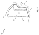
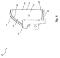
- the edge 23 may be at least partially concave in a bow or as in Fig. 1 to 4 . Fig. 9 . Fig. 11 and Fig. 15 represented convexly curved, or as in Fig. 5 and Fig. 6 shown at least partially straight. Combinations of the section-wise course of the edge 23 are also possible, as is an embodiment of the edge 23 as a free-form geometry.
- the OLED plate 02 is at least at its edges or a part of its peripheral edge 23 encapsulated by a plastic holder 03 and / or encapsulated.
- the plastic holder 03 thus forms an at least on a part of the peripheral edge 23 of the OLED plate 02 surrounding this plastic border.
- the plastic border surrounds the edge 23 of the OLED plate 02 at least in sections along those parts of the circumferential one Rands 23, in which the OLED plate 02 is encapsulated by the plastic holder 03 and / or encapsulated.
- the plastic holder 03 consists, at least in the region of the edges 23, of a plastic which is transparent at least for the light emitted by the OLED wafer within the part of the electromagnetic spectrum visible to the human eye.
- the OLED plate is at least at its edges 23 or part of its peripheral edge 23 of the plastic holder 03 at least in this area at least in the visible part of the electromagnetic spectrum of the electromagnetic spectrum transparent material encapsulated and / or encapsulated.
- At least one of the plastic holder 03 surrounding the OLED wafer 02, at least on a part of its peripheral edge 23, is arranged in a predetermined or desired direction deflecting coupling-out optical system 25 to the edges of the OLED wafer 02 surrounded by the plastic holder 03.
- the plastic holder 03 may be produced by injecting a film, which film may be provided with a coupling optics 25 forming, prefabricated, produced for example by printing and / or punching and / or deep drawing structure.
- the coupling-out optical system 25 can be produced by means of laser structuring of the plastic holder 03.
- Glass plates are preferably used for the front and / or rear encapsulation. Accordingly, a glass plate preferably forms the front side 21 and / or the rear side 22.
- a back-encapsulating layer may be made of, for example, a metal or a metal alloy.
- the OLED plate 02 can be overmolded and / or encapsulated completely or partially on the front or rear side of the plastic holder 03.
- the OLED plate 02 can additionally be overmolded on its rear side 22 and / or encapsulated.
- a light emitting or provided for light delivery front 21 and / or back 22 of the OLED plate 02 can each completely or partially from an at least on the corresponding, provided for the light output front 21 and / or rear side 22 made of transparent plastic plastic holder 03 molded and / or be cast.
- the OLED plate 02 can be completely or partly encapsulated by opaque material of the plastic holder 03 at the rear and / or be encapsulated, whereas the OLED plate 02 is carried out on its front side 21 either free of the plastic holder 03 or just as at its coated by the plastic holder 03 and / or edges 23 only from a plastic holder 03 from a at least for the human eye visible part of the electromagnetic spectrum transparent plastic may be completely or partially encapsulated and / or encapsulated. It should be emphasized that a combination of opaque plastic on the back 22 and transparent plastic on the edges 23 and on the front 21 by encapsulation or Umg suedung in a multi-stage injection molding process is conceivable.
- flow aids 30 may be provided in the form of, for example, ribs on the plastic holder 03.
- the flow aids 30 can additionally serve to increase the rigidity of the finished luminous means 01.
- the plastic holder 03 may be embodied as a conductor carrier produced in MID technology, at least part of whose conductor tracks are electrically connected to electrical connections of the OLED 20 of the at least one OLED wafer 02 and / or are electrically connectable.
- the plastic holder 03 simultaneously fulfills several functions, firstly the stress- and torque-free mounting of the at least one OLED wafer 02, secondly the electrical contacting of the OLED 20 of the OLED wafer 02 and thirdly the electrical continuation of the OLED 20 of the OLED wafer 02 with a arranged on the injection-molded circuit substrate, formed by at least one connected to the interconnects of the conductor track carrier produced or connectable electronic component electronic control circuit.
- the plastic holder 03 produced in MID technology thus forms a circuit carrier with its conductor tracks in addition to the at least one OLED 20 one or more further electronic components can be electrically contacted and mechanically fastened to the circuit carrier.
- a simple example of an electronic control circuit relates to the alignment of different brightness levels of individual OLEDs 20 or OLED strands within a group of jointly operated OLEDs 20.
- Such an electronic control circuit consists of at least one or more series resistors for adjusting the forward voltage of the OLEDs 20 to the electrical system. For example, it is conceivable to sort the OLEDs 20 according to forward voltage and intensity. To compensate for differences between multiple OLED lines, each consisting of series-connected OLEDs 20 of the same forward voltage and intensity, and to obtain a homogeneous brightness distribution of the adjacent OLED strands of OLEDs 20 with different forward voltage and intensity, at least each OLED strand provided with a different series resistor.
- OLDEs 20 also often require a separate failure detection when used as a light source, especially in vehicle lights. This is due to the low power consumption of OLEDs 20 in general.
- a control unit housed in a vehicle is not able to detect a change in power extraction from the vehicle electrical system corresponding to the failure of one or fewer OLEDs 20, since a resulting board voltage change is below the vehicle power supply voltage fluctuations occurring during normal operation of a vehicle.
- An electronic circuit arrangement for failure detection for example accommodated in the vehicle lamp, detects the failure of one or more OLEDs 20 in the vehicle lamp, for example by means of one or more comparators, and communicates this to the control unit.
- This electronic circuit arrangement for failure detection can be realized by an example applied to the illuminant carrier electronic control circuit.
- the electronic control circuit comprises in the simplest case a series resistor and optionally in addition a protective diode, but depending on the application may also contain substantially more electronic components, such as e.g. Microcontrollers or controllers, comparators, transistors, protective diodes, electrical resistors, for example as a series resistor, capacitors, ferrites, DC / DC converter circuits, etc.
- a light source 01 with one or more OLEDs 02 as a light source can comprise at least one further electronic component mentioned above.
- a light source 01 with one or more OLEDs 20 as light sources can have, in addition to the at least one OLED 20, at least one further electronic component.
- a particularly compactly constructed illuminant 01 can be obtained, which already comprises one or more electronic control circuits or parts thereof required for operating one or more OLEDs 20 as light sources.
- Fig. 9 1 shows an exemplary embodiment of a luminous means 01 with an OLED plate 02 encapsulated by a plastic holder 03, in which the edge 23 03 of the OLED plate 02 surrounding, transparent part of the plastic holder 03 optically effective surfaces are formed as a coupling-out optical system 25, which are used for light guidance and / or control.
- the optically effective surfaces of the coupling-out optical system 25 are designed as, for example, spherical, aspherical or free-form surfaces designed cushions.
- Fig. 10 shows this in an enlarged perspective view.
- Fig. 11 shows a further embodiment of a light source 01 with a molded plastic holder 03 OLED plate 02 in which on the edge 23 of the OLED plate 02 surrounding, transparent part of the plastic holder 03 optically effective surfaces are formed as Auskoppeloptik 25, the light guide and serve / or control.
- the optically effective surfaces of the coupling-out optical system 25 are designed as plane, spherical, aspherical or free-form surfaces designed prisms.
- Fig. 12 . Fig. 13 and Fig. 14 show this in an enlarged perspective view.
- Fig. 15 shows an additional embodiment of a light source 01 with a molded plastic holder 03 OLED plate 02 in which on the edge 23 of the OLED plate 02 surrounding, transparent part of the plastic holder 03 optically effective surfaces are formed as Auskoppeloptik 25, for light guidance and serve / or control.
- the optically active surfaces of the coupling-out optical system 25 are formed, for example in the form of planar, spherical, aspherical or free-form surfaces, in comparison to FIGS Fig. 11 . Fig. 12 . Fig. 13 . Fig. 14 shown embodiment aligned differently.
- Fig. 16 and Fig. 17 show this in an enlarged perspective view.
- Optically effective surfaces of the coupling-out optical system 25 may alternatively or additionally also be micro-optics.
- Targeted light control and / or deflection by coupling-out optics 25 in the area of the edge 23 of the OLED plate 02 encompassed by the plastic holder 03 may be particularly useful if, for example, no light can be emitted at all in certain solid angle ranges, such as the avoidance of radiation red light forward in the direction of travel of vehicles participating in the traffic. Such light, without additional Measures at the edges of an OLED wafer 02 radiates in a control technology and / or legally prohibited area, is guided by the Auskoppeloptik 25 at the edge region of the OLED wafer surrounding plastic holder 03 according to other areas and / or scattered and / or broken and / or otherwise deflected and / or controlled.
- such points or other geometries can be introduced by means of a laser on the surface or even in the transparent material or an underlying opaque material of the plastic holder 03 itself, not on the surface or incorporated, but within the volume of the body the plastic holder 03 are introduced.
- the material properties are locally changed by the laser energy in the transparent material, whereby scattering volume ranges are generated, which can be calculated and used for the light guidance.
- the light control and / or deflection can be used by means of the coupling-out optical system 25 to emit light of a light emerging in the region of the part of the plastic mount 03 provided with a coupling-out optical system 25 at the lower edge of the OLED chip 02 supply lateral light distribution, for example, for simultaneous fulfillment of a side marker light function by means provided for fulfilling a taillight function OLED plate 02nd
- the invention can be used when due to predetermined by a Strakverlauf geometry and / or design specifications in the lamp individual angular ranges for lighting functions are difficult or impossible to achieve, without additional optical elements in addition to the OLED itself.
- the invention uses the light emitted at the outer edge of an OLED plate 02 to fulfill a light function with a predetermined light distribution or at least to its contribution by the light emerging at the outer edge being deflected by the coupling-out optical system 25 in a desired direction.
- the invention thereby expands the field of application of OLEDs 20 embodied as OLED plates 02, in that at least a part of their edges, molded, briefly referred to as holder plastic holder 03 at least in the at least a portion of the edge comprising the edges comprehensive edge 23 of at least one is made in transparent to the human eye visible part of the electromagnetic spectrum transparent material.
- the holder is provided in its at least a portion of the edges comprising the edges comprehensive edge 23 of a transparent material at least in the visible part of the electromagnetic spectrum of the electromagnetic spectrum with integrally formed coupling-out optics 25.
- the coupling-out optics deflect the light emerging at the edges into such solid angle ranges or around that the light emerging there when leaving the vehicle light contributes to a given light distribution and / or does not leave the vehicle light in such solid angle ranges in which no light of a specific light function and color may leak.
- the coupling-out optical system 25 can be produced by means of subsequent laser structuring of the plastic holder 03.
- the plastic holder 03 may be provided to produce the plastic holder 03 by injecting a foil to be inserted into the recess of the mold, which foil may be provided with a prefabricated structure forming a coupling-out optical system, for example by printing and / or stamping and / or deep-drawing.
- the at least one support 40 can wholly or partially occupy a surface of the OLED wafer 02 forming a light output or provided for light emission or forming a front side 21 or rear side 22 of the OLED wafer 02, wherein the OLED wafer 02 with the corresponding surface on the at least a support 40 is placed in the recess of the mold 04.
- the OLED plate 02 is cooled at least during the introduction of the initially liquid plastic into the recess and during the waiting for the solidification of the plastic. In this way, it can be prevented that the at least one organic layer of the OLED 20 of the OLED plate 02 neither through the introduction of a possibly liquefied by heating plastic in the recess, is still damaged by an optionally occurring exothermic chemical Abbindevorgang while waiting for the solidification of at least initially liquid plastic.
- the at least one support 40 on which the OLED plate 02 in the recess of the mold 04 rests is in heat transfer connection with a heat sink or can be brought into such a connection.
- the support 40 may be in heat transferring communication with a heat sink by being cooled, such as through a channel of a cooling circuit incorporated into the support 40, through which a coolant may flow, for example circulate.
- Fig. 18 An alternative or additional possibility for cooling the OLED plate 02 at least during the introduction of the initially liquid plastic into the recess and during the waiting for the solidification of the plastic is in Fig. 18 shown.
- the cooling takes place by means of a plunger 05, which is lowered before introducing the initially liquid plastic onto at least part of the surface of the OLED plate 02 facing away from the at least one support 40 and lingers in this position until the plastic has solidified.
- the stamp 05 may be cooled, for example, passively by utilizing its heat capacity, wherein it is retracted to a cooler heat level when it is not lowered onto an OLED plate 02, or actively, the stamp 05 being in heat transfer connection with a heat sink, For example, by at least one channel 50 of a cooling circuit is incorporated in the stamp 05 through which a coolant flow, for example, can circulate.
- the support 40 may be formed such that the OLED plate 02 rests on at least one edge region on the support 40. A corresponding edge area which is laid on the support 40 remains free of the encapsulation or encapsulation by means of the plastic support 03.
- the OLED plate 02 preferably free of forces and moments on the at least one pad 40 in the Recess of the mold 04 is placed and is held stationary only by shaping the recess of the mold 04 and the support 40 during the encapsulation and / or encapsulation.
- the plastic can be added by heating in its initially liquid state, the solidification is achieved by cooling.
- a chemical setting process may take place during the solidification of the initially liquid plastic.
- the method may provide for the recess of the mold 04 to at least one entry or introduction opening for the initially liquid plastic and at least one discharge or escape opening for the initially liquid plastic during the encapsulation and / or encapsulation of the OLED plate 02 Its introduction into the recess displaced air to close.
- the remaining cavity, comprising the recess or encompassed by the recess, has a geometry corresponding to the outer shape of the finished luminous means.
- the method may additionally provide that the recess of the mold 04 has a depth which is greater than a thickness of the OLED wafer corresponding to the extension of the OLED wafer 02 from its front side 21 to its rear side 22 normal to front side 21 and rear side 22 02, wherein the recess is filled during the extrusion coating and / or pouring over the OLED plate 02.
- the method may provide for contacting electrical terminals of the OLED 20, for example by wire bonding or ACF bonding, before and after inserting the OLED chip 02 into the mold, and to connect them to the conductors serving for further contacting.
- the conductors can be guided out of the recess of the mold 04 before the OLED wafer 02 is coated with liquid plastic initially and / or encapsulated in a later process step.
- the method can provide before or after inserting the OLED plate 02 into the recess of the mold 04, to cover the electrical connections of the OLED 20 of the OLED plate 02 with a subsequently removable cover and thereby protect and of which in a later Procedural step in which the OLED plate 02 with initially liquid plastic molded and / or encapsulated, to keep plastic filled in the recess.
- the method may alternatively or additionally provide, if appropriate, to introduce electrical connections of the OLED 02 of the OLED wafer 02 connected or connectable interconnects in the recess, which then in a later process step, in which the OLED plate 02 with initially liquid plastic encapsulated and / or is encapsulated, also be encapsulated and / or encapsulated by the plastic.
- the method for the simultaneous formation of printed conductors on or in the plastic holder 03 produced by encapsulation and / or encapsulation of the OLED wafer 02 with initially liquid plastic can provide one or more methods of MID technology, such as two-component injection molding, MID hot stamping, laser Direct structuring, subtractive laser structuring, mask exposure methods, film back-injection, melting of a continuously fed copper wire and spraying onto the substrates with compressed air.
- the electrical connections of the OLED 20 can be connected after the production of the conductor tracks, for example by wire bonding or ACF bonding with at least a portion of the conductor tracks.
- the lamp 01 comprises a plurality of OLED plates 02, they are preferably spaced apart from each other and at least separated from each other by a web of the plastic holder 03.
- the invention provides a plastic-technical recording of glass bodies or bodies that contain glass parts or at least partially transparent or semi-transparent plastics, in particular OLEDs 20, preferably in vehicle lights.
- the recording takes place here by means of a Kunststoffumg discern- and / or -umspritzreaes.
- the at least on its front side 21 and / or back 22, for example, provided with glass plates for their encapsulation and thereby a glass body in the sense of the preceding embodiment performing OLED 20 is held by means of a Umg vision mixes and / or Umspritzrea with plastic and can thus to other parts of the vehicle lamp be tethered or be.
- Fig. 1 to Fig. 6 such as Fig. 9 to Fig. 17 show the structure with a of the plastic holder 03 not completely encompassed at the edge, as an OLED plate 02 running OLED 20.
- Advantageous here is a filigree and thus higher-quality appearance.
- a part of the edge 23 representing a glass edge 24 is exposed. This can be used, for example, for other light functions, such as a side marker light function whose main emission angle range is rotated 90 ° to the main emission direction of a taillight function. Therefore, the light extraction at this glass edge 24 can be used for another function.
- the encapsulation and / or encapsulation of the OLED plate 02 can be done over the entire surface, wherein the back 22 of the OLED plate 02 is included in the plastic holder 03 with.
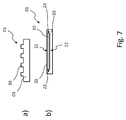
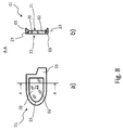
- the plastic holder 03 may further ring-shaped, C-shaped or in another encompassing shape, as in Fig. 7 and Fig. 8 is shown executed.
- an encapsulation or Umg cordung excluding the edge 23 of an OLED plate 02 as in Fig. 8 can be advantageously used an effect of slight shrinkage of the initially liquid plastic during its solidification in order to hold the OLED plate safely.
- the plastic holder 03 can be executed by means of encapsulation and / or encapsulation or by a combination of both.
- the plastic holder 03 may also support the OLED wafer 02 at least partially on its front side 21 and / or rear side 22 and / or at least partially grip the OLED wafer 02 on the edge 23.
- the disadvantage here is that the lighting electronics must provide the higher forward voltage.
- organic layers can be damaged irreversibly, so that they are no longer excitable to the light emission and the OLED 20 is thus destroyed photometrically.
- thermal stresses in the OLED plate are reduced or even avoidable.
- the invention is particularly industrially applicable in the field of production of vehicle lights, in particular vehicle lights, and components of vehicle lights, such as light sources and / or one or more electronic components and / or light sources comprehensive bulbs.
Landscapes
- Physics & Mathematics (AREA)
- Optics & Photonics (AREA)
- Electroluminescent Light Sources (AREA)
Priority Applications (1)
| Application Number | Priority Date | Filing Date | Title |
|---|---|---|---|
| EP16194191.9A EP3309854A1 (fr) | 2016-10-17 | 2016-10-17 | Moyen d'éclairage comprenant une delo pour phare de véhicule |
Applications Claiming Priority (1)
| Application Number | Priority Date | Filing Date | Title |
|---|---|---|---|
| EP16194191.9A EP3309854A1 (fr) | 2016-10-17 | 2016-10-17 | Moyen d'éclairage comprenant une delo pour phare de véhicule |
Publications (1)
| Publication Number | Publication Date |
|---|---|
| EP3309854A1 true EP3309854A1 (fr) | 2018-04-18 |
Family
ID=57137977
Family Applications (1)
| Application Number | Title | Priority Date | Filing Date |
|---|---|---|---|
| EP16194191.9A Pending EP3309854A1 (fr) | 2016-10-17 | 2016-10-17 | Moyen d'éclairage comprenant une delo pour phare de véhicule |
Country Status (1)
| Country | Link |
|---|---|
| EP (1) | EP3309854A1 (fr) |
Cited By (1)
| Publication number | Priority date | Publication date | Assignee | Title |
|---|---|---|---|---|
| CN113074351A (zh) * | 2021-04-07 | 2021-07-06 | 固安翌光科技有限公司 | 一种oled灯片及oled车灯 |
Citations (10)
| Publication number | Priority date | Publication date | Assignee | Title |
|---|---|---|---|---|
| DE20207799U1 (de) | 2002-05-17 | 2002-08-22 | FER Fahrzeugelektrik GmbH, 99817 Eisenach | Signalleuchte für Fahrzeuge |
| EP1367676A1 (fr) * | 2002-05-28 | 2003-12-03 | Eastman Kodak Company | Dispositif électroluminescent organique ayant un substrat flexible sur un support |
| EP1533633A1 (fr) * | 2003-11-21 | 2005-05-25 | Kabushiki Kaisha Toyota Jidoshokki | Dispositif d'illumination planaire |
| DE102005024838A1 (de) | 2005-05-27 | 2006-11-30 | Johnson Controls Headliner Gmbh | Beleuchtung für den Innen- oder Außenbereich eines Fahrzeuges mit einer OLED |
| DE102007021179A1 (de) | 2007-05-05 | 2008-11-06 | Dr. Ing. H.C. F. Porsche Aktiengesellschaft | Kraftfahrzeugleuchte |
| DE102009009087A1 (de) | 2009-02-14 | 2010-08-19 | Hella Kgaa Hueck & Co. | Beleuchtungseinrichtung für ein Kraftfahrzeug |
| WO2010116300A1 (fr) | 2009-04-08 | 2010-10-14 | Koninklijke Philips Electronics N. V. | Dispositif delo à apparence esthétique |
| US20110089811A1 (en) | 2001-12-28 | 2011-04-21 | Semiconductor Energy Laboratory Co., Ltd. | Method for fabricating a semiconductor device |
| EP2592331A1 (fr) | 2011-11-09 | 2013-05-15 | Valeo Vision | Dispositif d'éclairage et/ou de signalisation d'un véhicule automobile comprenant une source surfacique de lumière |
| US20150028314A1 (en) * | 2012-02-08 | 2015-01-29 | Panasonic Corporation | Organic electroluminescent light emitting device and method for manufacturing same |
-
2016
- 2016-10-17 EP EP16194191.9A patent/EP3309854A1/fr active Pending
Patent Citations (10)
| Publication number | Priority date | Publication date | Assignee | Title |
|---|---|---|---|---|
| US20110089811A1 (en) | 2001-12-28 | 2011-04-21 | Semiconductor Energy Laboratory Co., Ltd. | Method for fabricating a semiconductor device |
| DE20207799U1 (de) | 2002-05-17 | 2002-08-22 | FER Fahrzeugelektrik GmbH, 99817 Eisenach | Signalleuchte für Fahrzeuge |
| EP1367676A1 (fr) * | 2002-05-28 | 2003-12-03 | Eastman Kodak Company | Dispositif électroluminescent organique ayant un substrat flexible sur un support |
| EP1533633A1 (fr) * | 2003-11-21 | 2005-05-25 | Kabushiki Kaisha Toyota Jidoshokki | Dispositif d'illumination planaire |
| DE102005024838A1 (de) | 2005-05-27 | 2006-11-30 | Johnson Controls Headliner Gmbh | Beleuchtung für den Innen- oder Außenbereich eines Fahrzeuges mit einer OLED |
| DE102007021179A1 (de) | 2007-05-05 | 2008-11-06 | Dr. Ing. H.C. F. Porsche Aktiengesellschaft | Kraftfahrzeugleuchte |
| DE102009009087A1 (de) | 2009-02-14 | 2010-08-19 | Hella Kgaa Hueck & Co. | Beleuchtungseinrichtung für ein Kraftfahrzeug |
| WO2010116300A1 (fr) | 2009-04-08 | 2010-10-14 | Koninklijke Philips Electronics N. V. | Dispositif delo à apparence esthétique |
| EP2592331A1 (fr) | 2011-11-09 | 2013-05-15 | Valeo Vision | Dispositif d'éclairage et/ou de signalisation d'un véhicule automobile comprenant une source surfacique de lumière |
| US20150028314A1 (en) * | 2012-02-08 | 2015-01-29 | Panasonic Corporation | Organic electroluminescent light emitting device and method for manufacturing same |
Cited By (2)
| Publication number | Priority date | Publication date | Assignee | Title |
|---|---|---|---|---|
| CN113074351A (zh) * | 2021-04-07 | 2021-07-06 | 固安翌光科技有限公司 | 一种oled灯片及oled车灯 |
| US12359785B2 (en) | 2021-04-07 | 2025-07-15 | Gu'an Yeolight Technology Co., Ltd. | OLED lamp panel with display peripheral regions and display region of regular shape formed by plurality of light emitting units of the same shape, and lighting device having the same |
Similar Documents
| Publication | Publication Date | Title |
|---|---|---|
| DE102008025398B4 (de) | Schutzumhüllung für ein LED-Band | |
| EP2317213B1 (fr) | Module de diode luminescente d'un dispositif d'éclairage de véhicule automobile et dispositif d'éclairage de véhicule automobile | |
| EP3825601B1 (fr) | Élément lumineux pour un véhicule automobile et véhicule automobile | |
| DE202013105597U1 (de) | Leuchtmittel und hiermit ausgestattete Kraftfahrzeugleuchte | |
| DE102015206471A1 (de) | Beleuchtungseinrichtung | |
| EP2824387A1 (fr) | Elément conducteur de lumière, son procédé de fabrication, ainsi que moyen d'éclairage et lampe de véhicule automobile dotés d'un tel élément conducteur de lumière | |
| EP2525138B1 (fr) | Phare de véhicule automobile et son procédé de fabrication | |
| EP2269238A1 (fr) | Boîtier pour del de forte puissance | |
| EP2886936A1 (fr) | Agent lumineux et lampe de véhicule automobile équipée de celui-ci | |
| EP3210444B1 (fr) | Appareil d'éclairage extérieur pour véhicule automobile | |
| WO2009077105A1 (fr) | Corps d'éclairage avec des puces de del, et leur fabrication | |
| EP3147554A1 (fr) | Une source lumineuse pour phares de vehicules comprenant delo et son procede de fabrication | |
| EP2664496B1 (fr) | Procédé destiné à la fabrication de lampes de véhicules automobiles | |
| EP3309854A1 (fr) | Moyen d'éclairage comprenant une delo pour phare de véhicule | |
| EP2955063A1 (fr) | Lampe de véhicule automobile | |
| DE202013105487U1 (de) | Kraftfahrzeugleuchte | |
| WO2005056269A2 (fr) | Procede pour produire des diodes electroluminescentes a semi-conducteurs sur une platine, et unites lumineuses a platine integree | |
| EP3409439B1 (fr) | Dispositif optique, agencement d'éclairage, phares et procédé | |
| DE102011077658A1 (de) | Beleuchtungsvorrichtung mit verbesserter Wärmeableitungsfähigkeit | |
| DE102009038523A1 (de) | Leuchtmittel sowie Leuchte | |
| EP2900038B1 (fr) | Agent lumineux et lampe de véhicule automobile équipée de celui-ci | |
| EP2900039B1 (fr) | Ampoule, phare de véhicule automobile équipé de celle-ci et son procédé de fonctionnement | |
| EP2743572A1 (fr) | Elément conducteur de lumière avec surface à action optique fabriqués séparément par déformage | |
| DE102017219797A1 (de) | Lichtleitersystem mit Sensoren, Scheinwerfer mit Lichtleitersystem und Fahrzeug | |
| EP2357395A1 (fr) | Unité d'éclairage avec conduit de lumière |
Legal Events
| Date | Code | Title | Description |
|---|---|---|---|
| PUAI | Public reference made under article 153(3) epc to a published international application that has entered the european phase |
Free format text: ORIGINAL CODE: 0009012 |
|
| STAA | Information on the status of an ep patent application or granted ep patent |
Free format text: STATUS: THE APPLICATION HAS BEEN PUBLISHED |
|
| AK | Designated contracting states |
Kind code of ref document: A1 Designated state(s): AL AT BE BG CH CY CZ DE DK EE ES FI FR GB GR HR HU IE IS IT LI LT LU LV MC MK MT NL NO PL PT RO RS SE SI SK SM TR |
|
| AX | Request for extension of the european patent |
Extension state: BA ME |