EP3309906B1 - Kartenverbinder - Google Patents
Kartenverbinder Download PDFInfo
- Publication number
- EP3309906B1 EP3309906B1 EP16807593.5A EP16807593A EP3309906B1 EP 3309906 B1 EP3309906 B1 EP 3309906B1 EP 16807593 A EP16807593 A EP 16807593A EP 3309906 B1 EP3309906 B1 EP 3309906B1
- Authority
- EP
- European Patent Office
- Prior art keywords
- engaging portion
- card
- slider
- inclined face
- abuttable
- Prior art date
- Legal status (The legal status is an assumption and is not a legal conclusion. Google has not performed a legal analysis and makes no representation as to the accuracy of the status listed.)
- Active
Links
Images


Classifications
-
- H—ELECTRICITY
- H01—ELECTRIC ELEMENTS
- H01R—ELECTRICALLY-CONDUCTIVE CONNECTIONS; STRUCTURAL ASSOCIATIONS OF A PLURALITY OF MUTUALLY-INSULATED ELECTRICAL CONNECTING ELEMENTS; COUPLING DEVICES; CURRENT COLLECTORS
- H01R13/00—Details of coupling devices of the kinds covered by groups H01R12/70 or H01R24/00 - H01R33/00
- H01R13/62—Means for facilitating engagement or disengagement of coupling parts or for holding them in engagement
- H01R13/629—Additional means for facilitating engagement or disengagement of coupling parts, e.g. aligning or guiding means, levers, gas pressure electrical locking indicators, manufacturing tolerances
- H01R13/633—Additional means for facilitating engagement or disengagement of coupling parts, e.g. aligning or guiding means, levers, gas pressure electrical locking indicators, manufacturing tolerances for disengagement only
- H01R13/635—Additional means for facilitating engagement or disengagement of coupling parts, e.g. aligning or guiding means, levers, gas pressure electrical locking indicators, manufacturing tolerances for disengagement only by mechanical pressure, e.g. spring force
-
- G—PHYSICS
- G06—COMPUTING OR CALCULATING; COUNTING
- G06K—GRAPHICAL DATA READING; PRESENTATION OF DATA; RECORD CARRIERS; HANDLING RECORD CARRIERS
- G06K13/00—Conveying record carriers from one station to another, e.g. from stack to punching mechanism
- G06K13/02—Conveying record carriers from one station to another, e.g. from stack to punching mechanism the record carrier having longitudinal dimension comparable with transverse dimension, e.g. punched card
- G06K13/08—Feeding or discharging cards
- G06K13/0806—Feeding or discharging cards using an arrangement for ejection of an inserted card
- G06K13/0825—Feeding or discharging cards using an arrangement for ejection of an inserted card the ejection arrangement being of the push-push kind
-
- G—PHYSICS
- G06—COMPUTING OR CALCULATING; COUNTING
- G06K—GRAPHICAL DATA READING; PRESENTATION OF DATA; RECORD CARRIERS; HANDLING RECORD CARRIERS
- G06K13/00—Conveying record carriers from one station to another, e.g. from stack to punching mechanism
- G06K13/02—Conveying record carriers from one station to another, e.g. from stack to punching mechanism the record carrier having longitudinal dimension comparable with transverse dimension, e.g. punched card
- G06K13/08—Feeding or discharging cards
- G06K13/085—Feeding or discharging cards using an arrangement for locking the inserted card
- G06K13/0856—Feeding or discharging cards using an arrangement for locking the inserted card the locking arrangement comprising a notch in the card and a complementary locking means in the card reading station
-
- H—ELECTRICITY
- H01—ELECTRIC ELEMENTS
- H01R—ELECTRICALLY-CONDUCTIVE CONNECTIONS; STRUCTURAL ASSOCIATIONS OF A PLURALITY OF MUTUALLY-INSULATED ELECTRICAL CONNECTING ELEMENTS; COUPLING DEVICES; CURRENT COLLECTORS
- H01R12/00—Structural associations of a plurality of mutually-insulated electrical connecting elements, specially adapted for printed circuits, e.g. printed circuit boards [PCB], flat or ribbon cables, or like generally planar structures, e.g. terminal strips, terminal blocks; Coupling devices specially adapted for printed circuits, flat or ribbon cables, or like generally planar structures; Terminals specially adapted for contact with, or insertion into, printed circuits, flat or ribbon cables, or like generally planar structures
- H01R12/70—Coupling devices
- H01R12/71—Coupling devices for rigid printing circuits or like structures
- H01R12/712—Coupling devices for rigid printing circuits or like structures co-operating with the surface of the printed circuit or with a coupling device exclusively provided on the surface of the printed circuit
- H01R12/716—Coupling device provided on the PCB
-
- H—ELECTRICITY
- H01—ELECTRIC ELEMENTS
- H01R—ELECTRICALLY-CONDUCTIVE CONNECTIONS; STRUCTURAL ASSOCIATIONS OF A PLURALITY OF MUTUALLY-INSULATED ELECTRICAL CONNECTING ELEMENTS; COUPLING DEVICES; CURRENT COLLECTORS
- H01R12/00—Structural associations of a plurality of mutually-insulated electrical connecting elements, specially adapted for printed circuits, e.g. printed circuit boards [PCB], flat or ribbon cables, or like generally planar structures, e.g. terminal strips, terminal blocks; Coupling devices specially adapted for printed circuits, flat or ribbon cables, or like generally planar structures; Terminals specially adapted for contact with, or insertion into, printed circuits, flat or ribbon cables, or like generally planar structures
- H01R12/70—Coupling devices
- H01R12/71—Coupling devices for rigid printing circuits or like structures
- H01R12/72—Coupling devices for rigid printing circuits or like structures coupling with the edge of the rigid printed circuits or like structures
-
- H—ELECTRICITY
- H01—ELECTRIC ELEMENTS
- H01R—ELECTRICALLY-CONDUCTIVE CONNECTIONS; STRUCTURAL ASSOCIATIONS OF A PLURALITY OF MUTUALLY-INSULATED ELECTRICAL CONNECTING ELEMENTS; COUPLING DEVICES; CURRENT COLLECTORS
- H01R13/00—Details of coupling devices of the kinds covered by groups H01R12/70 or H01R24/00 - H01R33/00
- H01R13/62—Means for facilitating engagement or disengagement of coupling parts or for holding them in engagement
- H01R13/629—Additional means for facilitating engagement or disengagement of coupling parts, e.g. aligning or guiding means, levers, gas pressure electrical locking indicators, manufacturing tolerances
-
- H—ELECTRICITY
- H01—ELECTRIC ELEMENTS
- H01R—ELECTRICALLY-CONDUCTIVE CONNECTIONS; STRUCTURAL ASSOCIATIONS OF A PLURALITY OF MUTUALLY-INSULATED ELECTRICAL CONNECTING ELEMENTS; COUPLING DEVICES; CURRENT COLLECTORS
- H01R13/00—Details of coupling devices of the kinds covered by groups H01R12/70 or H01R24/00 - H01R33/00
- H01R13/62—Means for facilitating engagement or disengagement of coupling parts or for holding them in engagement
- H01R13/639—Additional means for holding or locking coupling parts together, after engagement, e.g. separate keylock, retainer strap
Definitions
- the invention relates to card connectors.
- the card connector includes a body, a slider, a lock spring, a first spring, and a second spring.
- the body has a slot, a movement path, and a rib.
- the slot is a space in the body for insertion and removal of a card.
- the movement path is provided next to the slot of the body and extends in the card-insertion/removal-direction of the card.
- the rib is disposed in the movement path.
- the slider is provided such as to be slidable in the movement path of the body, together with the card, from a first position to a third position beyond a second position. The slider is located at the second position in the initial state.
- the second position is located on the card-discharge-direction side relative to the first position.
- the third position is located on the card-discharge-direction side relative to the second position.
- the lock spring is provided at the slider and is movable in the insertion/removal direction together with the slider.
- the lock spring includes an engaging portion engageable with an engaging recess of the card. When the slider is located at the second position, the engaging portion of the lock spring does not abut the rib and therefore can be displaced away from the engaging recess of the card. The displacement of the engaging portion of the lock spring away from the engaging recess of the card causes release of the engagement between the engaging portion of the lock spring and the engaging recess of the card.
- the engaging portion of the lock spring abuts the rib of the body, which prevents displacement of the engaging portion of the lock spring away from the engaging recess of the card.
- the first spring applies an urging force to the slider in the discharge direction.
- the second spring elastically contacts the slider to cause the slider to lose momentum and presses the slider back to the second position.
- Patent Literature 1 WO 2005/034295
- the slider Since the slider is configured to be movable in the discharge direction, beyond the second position and up to the third position, it is difficult to reduce the dimension in the insertion/removal direction of the card connector.
- the above card connector has a complicated configuration due to requirement to allow release of the engagement between the lock spring and the engaging recess of the card with the slider located at the second position, and also due to requirement to maintain the engagement between the lock spring and the engaging recess of the card with the slider located at the third position.
- the invention has been devised in view of the above circumstances and provides a card connector with a reduced size and a simplified structure.
- the invention is set out in claim 1.
- a card connector of an aspect of the invention includes a body, a slider, an urging member, and a lock spring.
- the body includes a slot, a movement path, and an abuttable portion.
- a card can be inserted into and removed from the slot along a first direction.
- the movement path extends in the first direction and is located on one side of a second direction relative to the slot.
- the second direction crosses the first direction.
- the abuttable portion is provided inside the movement path and includes an inclined face.
- the inclined face is inclined in a direction including components of one side of the first direction and the other side of the second direction.
- the slider is accommodated inside the movement path so as to be movable in the first direction, at least between a first position and a second position.
- the second position is located on the one side of the first direction relative to the first position.
- the urging member exerts on the slider an urging force to the one side of the first direction.
- the lock spring is provided at the slider and movable in the first direction together with the slider.
- the lock spring includes an engaging portion.
- the engaging portion is engageable with an engaging recess of the card, from the one side of the second direction.
- the lock spring is elastically deformable such that the engaging portion thereof is displaced to the one side of the second direction.
- the card connector of this aspect has the following technical features.
- the conventional card connector described above is configured to prevent the card from springing out by bringing the lock spring into abutment with the rib when the slider is located at the third position that is located on the discharge-direction side relative to the second position.
- the card connector of the invention is configured such that the engaging portion of the lock spring is brought into abutment with the inclined face of the abuttable portion when the slider is located at the second position, so that the slider does not move to the one side of the first direction beyond the second position. Therefore, the card connector of the invention has a reduced dimension in the first direction (the card connector is downsized).
- the card connector has a simplified construction.
- this card connector has a simple configuration to allow two operations in a state where the slider is located at the second position: preventing a card from spring-out and removing the card. Specifically, when the urging force of the urging member causes the slider to move to the one side of the first direction (in the card discharge direction), from the first position to the second position, the engaging portion of the lock spring is brought into abutment with the inclined face of the abuttable portion of the body.
- the inclined face is inclined in the direction including the components of the one side of the first direction and the other side of the second direction, a force is generated against the load on the inclined face upon the abutment, and the force acts on the engaging portion in the direction including components of the other side of the first direction and the other side of the second direction.
- This force prevents displacement of the engaging portion to the one side of the second direction and maintains the engagement of the engaging portion with the engaging recess of the card. The card is thus prevented from springing out of the card connector.
- the engaging portion may include an inclined portion.
- the inclined portion may be inclined in a direction that is substantially the same as an inclining direction of the inclined face and be configured to make surface-contact with the inclined face.
- the engaging portion is easy to be displaced to the one side of the second direction along the inclined face of the abuttable portion when the engaging portion is subjected to a load from a card in the direction including the components of the one side of the first direction and the one side of the second direction. This is because the load from the card is allowed to be transferred more easily from the inclined portion of the engaging portion to the inclined face of the abuttable portion, and the force generated against the load is allowed to act as a force for displacing the engaging portion along the inclined face of the abuttable portion.
- the engaging portion may be elastically deformable when brought into abutment with the inclined face of the abuttable portion.
- elastic deformation of the engaging portion mitigates impact occurring when the engaging portion is brought into abutment with the inclined face of the abuttable portion.
- the engaging portion may be constituted by a flat spring of hook shape.
- the engaging portion may be constituted by an elastic body of rubber or other material.
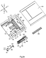
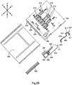
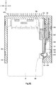
- a card connector C of an embodiment of the invention will be described with reference to Figs. 1A to 3E .
- the card connector C is a connector for connection with a card M. These will be described in detail below.
- the Y-Y' direction indicated in Figs. 2A to 3E corresponds to the insertion/removal direction of the card M with respect to the card connector C and corresponds to the first direction in the claims.
- the Y direction corresponds to the discharge direction of the card M and corresponds to one side of the first direction in the claims
- the Y' direction corresponds to the insertion direction of the card M (opposite to the discharge direction) and corresponds to the other side of the first direction.
- the X direction corresponds to one side of the second direction in the claims
- the X' direction corresponds to the other side of the second direction in the claims.
- the Z-Z' direction indicated in Figs. 2A and 2B orthogonally crosses the Y-Y' and X-X' directions.
- the card M is, for example, an IC card, a PC card, a SIM card, an SD card, a mini SD card, or the like.
- the card M includes an engaging recess M1 and a plurality of electrodes (not shown).
- the engaging recess M1 is provided centrally in the end portion on the X-direction side of the card M.
- the electrodes are provided on an end face on the Z'-direction side (i.e. bottom face) of the card M.
- the card connector C includes a body 100, a plurality of terminals 200, a slider 300, a lock spring 400, and an urging member 500.
- the body 100 is made of an insulating plastic.
- the body 100 includes a slot 110.
- the slot 110 is a recess in the body 100 and extends in the Y-Y' direction.
- the slot 110 opens at least in the Y direction.
- the slot 110 may or may not open in the Z direction.
- the slot 110 has an X-X' direction dimension corresponding to that of the card M.
- the slot 110 is smaller in Y-Y' direction dimension than the card M.
- the card M can be inserted into and removed from the slot 110 along the Y-Y' direction.
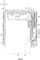
- Fig. 3B illustrates the card M located at a connection position where the card M is connected to the card connector C.
- Fig. 3C illustrates the card M located at a discharge position where the card M can be discharged from the slot 110 of the card connector C.
- Each of the terminals 200 includes a contact portion 210 and a connection portion 220.
- the terminals 200 may preferably be held in the body 100 such that the contact portions 210 are located within the slot 110 and the connection portions 220 protrude outwards from the body 100.
- the terminals 200 may be insert-molded in the body 100, or may be respectively held in holding grooves or holding holes (not shown) in the body 100.
- the contact portions 210 are arranged in accordance with the positions of the electrodes of the card M as located at the connection position.
- the connection portions 220 are arranged in accordance with the positions of electrodes of a circuit board (not shown) or other member to mount the card connector C.
- the terminals 200 are insert-molded in the body 100 such that the contact portions 210 are located inside the slot 110 and the connection portions 220 protrude in the Y' direction from the Y' end face of the body 100.
- the body 100 further includes a movement path 120.
- the movement path 120 is provided on the X-direction side relative to the slot 110 of the body 100 and extends in the Y-Y' direction.
- the movement path 120 communicates with the slot 110.
- the movement path 120 accommodates the slider 300.
- the slider 300 is movable, together with the card M, in the Y-Y' direction at least between a first position and a second position in the movement path 120.
- the first position is the position of the slider 300 when the card M is located at the connection position.
- the second position which is on the Y-direction side relative to the first position, is the position of the slider 300 when the card M is located at the discharge position.
- the second position is also the initial position of the slider 300 when the card M is not inserted.
- the movement path 120 may include an X-direction-side guide 121 and an X'-direction-side guide 122.
- the guide 121 and the guide 122 are only required to guide the slider 300 movably in the Y-Y' direction between the guides 121 and 122.
- the guide 121 may have any one of the following configurations: an X-direction-side wall face of the movement path 120, a ridge in the movement path 120 extending in the Y-Y' direction, a plurality of protrusions in the movement path 120 at spaced intervals in the Y-Y' direction, or the like.
- the guide 122 may have any one of the following configurations: an X'-direction-side wall face of the movement path 120, a ridge in the movement path 120 extending in the Y-Y' direction, a plurality of protrusions in the movement path 120 at spaced intervals in the Y-Y' direction, or the like.
- the guide 122 has a Z-Z' direction dimension that does not interfere with the slider 300 and the lock spring 400.
- the movement path 120 and the slot 110 communicate with each other on the Z-direction side relative to the guide 122.
- the guide 122 may be provided with an opening for avoiding interference with the slider 300 and the lock spring 400. In this case, the movement path 120 and the slot 110 communicate with each other through the opening.
- the slider 300 may include an X-direction-side runner 310 and an X'-direction-side runner 320.
- the runner 310 is only required to be movable in the Y-Y' direction along the guide 121, and the runner 320 is only required to be movable in the Y-Y' direction along the guide 122.
- the runner 310 may have any one of the following configurations: an X-direction-side end face of the slider 300, a ridge on the slider 300 extending in the Y-Y' direction, a plurality of protrusions on the slider 300 at spaced intervals in the Y-Y' direction, or the like.
- the runner 320 may have any one of the following configurations: an X'-direction-side end face of the slider 300, a ridge on the slider 300 extending in the Y-Y' direction, a plurality of protrusions on the slider 300 at spaced intervals in the Y-Y' direction, or the like.
- the guide 121 is the X-direction-side wall face of the movement path 120
- the guide 122 is a ridge being provided at the X'-direction end of the bottom face of the movement path 120 and extending in the Y-Y' direction.
- the runner 310 is the X-direction-side end face of the slider 300
- the runner 320 is a ridge being provided on the Z'-direction-side face of the slider 300 and extending in the Y-Y' direction.
- the urging member 500 is only required to exert on the slider 300 an urging force in the Y direction.
- the urging member 500 may be a coil spring, a flat spring, a plastic plate, or an elastic body of rubber or other material.
- the urging member 500 may be disposed in a compressed state between the slider 300 and part of the body 100, or may be positionally fixed in the body 100 so as to be able to urge the slider 300 in the Y direction.
- the urging member 500 may be disposed inside or outside the movement path 120 of the body 100.
- the urging member 500 is a coil spring disposed inside the movement path 120 in a compressed state, between the Y'-direction-side wall of the movement path 120 and the slider 300.
- the Y'-direction-side wall of the movement path 120 is provided with a column 140 received in the urging member 500.
- the Y'-direction-side end portion of the slider 300 is provided with an accommodating recess 330 for accommodating the Y-direction-side end portion of the urging member 500.
- the slider 300 may preferably further include a holding portion 340.
- the holding portion 340 holds the lock spring 400.
- the holding portion 340 may be a holding groove or a holding hole for holding the lock spring 400 partly, or may be a portion of the slider 300 in which the lock spring 400 is partly insert-molded.
- the holding portion 340 may be provided at any position in the slider 300.
- the holding portion 340 may be provided on the Z'-direction-side face of the slider 300, or may be a part of the Y-direction-side end portion of the slider 300.
- the holding portion 340 includes a block and a holding groove.
- the block is provided on the X-direction side relative to the runner 320 on the Z'-direction-side face of the slider 300.
- the holding groove is provided in the block.
- the lock spring 400 includes an engaging portion 410.
- the lock spring 400 is only required to be elastically deformable such that the engaging portion 410 is displaced in the X direction.
- the lock spring 400 is constituted by a flat spring, plastic, rubber, a combination of a flat spring and plastic, a combination of a flat spring and rubber, a combination of plastic and rubber, a combination of a flat spring, plastic, and rubber, etc.
- the engaging portion 410 partly protrudes in the X' direction from the slider 300 and is partly located inside the slot 110.
- the engaging portion 410 is engageable with the engaging recess M1 of the card M.
- the body 100 further includes an abuttable portion 130.
- the abuttable portion 130 is only required to be located inside the movement path 120 and includes an inclined face 131.
- the abuttable portion 130 may be, for example, a rib inside the movement path 120 or a portion of a wall of the movement path 120.
- the inclined face 131 is inclined in a direction having components of the Y and X' directions.
- the inclined face 131 may be flat (level) with respect to the Z-Z' direction, or may be also inclined in either the Z direction or the Z' direction.
- Figs. 3A to 3E show the former case.
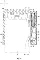
- the inclined face 131 of the abuttable portion 130 is a portion of the body 100 that is abuttable on the engaging portion 410 of the lock spring 400 from the Y-direction side when the slider 300 is located at the second position.
- the engaging portion 410 is brought into abutment with the inclined face 131, generated is a force against the load exerted on the inclined face 131. Since the inclined face 131 is inclined as described above, this force acts on the engaging portion 410 in a direction having components of the Y' and X' directions. This action prevents displacement in the X direction of the engaging portion 410.
- the engaging portion 410 When the engaging portion 410 is not engaged with the engaging recess M1 of the card M, the engaging portion 410 is retained in abutment with the inclined face 131 because of the prevention of displacement of the engaging portion 410 and the urging force in the Y direction of the urging member 500. The slider 300 is thus retained at the second position.
- the engaging portion 410 When the engaging portion 410 is engaged with the engaging recess M1 of the card M, the engagement therebetween is maintained because of the prevention of displacement of the engaging portion 410.
- the card M is thus prevented from springing out of the slot 110 of the card connector C.
- the engaging portion 410 may be configured to be elastically deformable when brought into abutment with the inclined face 131 of the abuttable portion 130.
- the engaging portion 410 may be a flat spring or a plastic plate bent in a hook shape, or an elastic body of rubber or other material.
- the portion other than the engaging portion 410 of the lock spring 400 may be a flat spring or a plastic plate integrally formed with the engaging portion 410, or may be a plastic member or an elastic body connected to the engaging portion 410.
- the portion other than the engaging portion 410 of the lock spring 400 may be an elastic body of rubber or other material integrally formed with the engaging portion 410, or may be a flat spring or a plastic member connected to the engaging portion 410.
- the engaging portion 410 may be configured to elastically deform such that the Y-Y' direction dimension of the engaging portion 410 decreases upon abutment.
- the engaging portion 410 may be configured to elastically deform such that the Y-Y' direction dimension of the engaging portion 410 decreases and the X-X' direction dimension of the engaging portion 410 increases upon abutment.
- Fig. 3E shows the latter case.
- the engaging portion 410 may include a first inclined portion 411 (corresponding to the inclined portion in the claims).
- the first inclined portion 411 extends in the same direction as the inclining direction of the inclined face 131 of the abuttable portion 130.
- the first inclined portion 411 may be in surface-contact with the inclined face 131 of the abuttable portion 130.
- the lock spring 400 may further include a base 420 and an intermediate portion 430.
- the base 420 is held by the holding portion 340 of the slider 300.
- the intermediate portion 430 extends in the Y-Y' direction from the base 420 to the engaging portion 410. When the engaging portion 410 is displaced in the X direction, the intermediate portion 430 elastically deforms in the X direction.
- the lock spring 400 is constituted by a flat spring.
- the base 420 of the lock spring 400 is generally L-shaped and is press-fitted and held in the holding groove of the holding portion 340.
- the intermediate portion 430 of the lock spring 400 is a rectilinear plate extending in the Y-Y' direction along the X-direction-side face of the runner 320 and is elastically deformable in the X direction.
- the runner 320 limits the extent of elastic deformation in the X' direction of the intermediate portion 430.
- the engaging portion 410 of the lock spring 400 is bent in a hook shape.
- the engaging portion 410 includes the first inclined portion 411, a second inclined portion 412, and a joining portion 413.
- the second inclined portion 412 extends substantially parallel to the first inclined portion 411.
- the joining portion 413 interjoins the X'-direction-side end of the first inclined portion 411 and the X'-direction-side end of the second inclined portion 412.
- the corner where the second inclined portion 412 and the joining portion 413 meet is located inside the slot 110 and serves as a portion to engage with the engaging recess M1 of the card M. It is possible to omit the second inclined portion 412 and the joining portion 413.
- the slider 300 further includes a projection 350.
- the projection 350 protrudes in the X' direction from the slider 300.
- the projection 350 is located inside the slot 110.
- the guide 122 if provided, may preferably have such a Z-Z' direction dimension that the guide 122 does not interfere with the projection 350, or may be provided with an opening for avoiding interference with the projection 350.
- the card M may further include a fitting recess M2 that can fit over the projection 350.
- the fitting recess M2 is provided at a corner at the X- and Y'-direction side of the card M and opens in the X and Y' directions.
- the fitting recess M2 may have a shape conforming to the outer shape of the projection 350.
- the projection 350 When the slider 300 is located at the second position, the projection 350 fits in the fitting recess M2. When the slider 300 moves from the second position to the first position, the projection 350 is pressed by the card M. In contrast, when an urging force of the urging member 500 causes the slider 300 to move from the first position to the second position, the projection 350 presses the card M. It should be appreciated that the projection 350 may be omitted if the slider 300 is movable together with the card M only by the engagement between the engaging portion 410 of the lock spring 400 and the engaging recess M1 of the card M.
- the card connector C may further include a heart-cam mechanism H.
- the heart-cam mechanism H includes a pin HI and a cam groove H2.
- the cam groove H2 is provided in the Z-direction-side face of the slider 300.
- the pin HI is generally U-shaped and has first and second longitudinal ends. The first end of the pin HI is rotatably supported by the Y-direction-side wall of the movement path 120 of the body 100. The second end of the pin HI is received in the cam groove H2 such as to be movable inside the cam groove H2 in accordance with movement of the slider 300.
- the cam groove H2 is shaped such as to positionally fix the second end of the pin HI when the slider 300 is pressed in the Y' direction beyond the first position, and such as to release the positional fixation of the second end when the slider 300 is pressed again in the Y' direction. If the card connector C is provided with the heart-cam mechanism H as described above, the slider 300 may move beyond the first position and up to the third position where the heart-cam mechanism H is positionally fixed or released. The third position is a position on the Y'-direction side relative to the first position. It should be noted that the heart-cam mechanism H may be omitted.
- the card connector C may further include a cover 600.
- the cover 600 is attached to the body 100 and covers the movement path 120 at least from the Z-direction side. If the slot 110 of the body 100 opens in the Z direction, the cover 600 covers the slot 110 and the movement path 120.
- the cover 600 may include the urging member 500. For example, a portion of the cover 600 may be cut and bent toward the movement path 120. In this case, the urging member 500 forms a flat spring constituted by the portion of the cover 600. It should be noted that the cover 600 may be omitted.
- the lock spring 400 and the slider 300 are prepared.
- the base 420 of the lock spring 400 is held by the holding portion 340 of the slider 300, the intermediate portion 430 of the lock spring 400 is disposed on the X-direction side relative to the runner 320 of the slider 300, and the engaging portion 410 of the lock spring 400 is made to protrude from the slider 300 in the X' direction.
- the urging member 500 is prepared.
- the Y-direction-side end portion of the urging member 500 is accommodated in the accommodating recess 330 of the slider 300.
- the body 100 and the plurality of terminals 200 are prepared.
- the terminals 200 are insert-molded inside the body 100, the contact portions 210 of the terminals 200 are disposed inside the slot 110, and the connection portions 220 of the terminals 200 protrude from the body 100 in the Y' direction.
- the column 140 of the body 100 is inserted into the Y'-direction-side end portion of the urging member 500, and the slider 300 and the lock spring 400 are accommodated in the movement path 120 of the body 100.
- the runner 310 of the slider 300 is disposed such as to be movable in the Y-Y' direction along the guide 121 of the movement path 120
- the runner 320 of the slider 300 is disposed such as to be movable the Y-Y' direction along the guide 122 of the movement path 120.
- the pin HI of the heart-cam mechanism H is prepared.
- the first end of the pin HI is attached to the Y-direction-side wall of the movement path 120 of the body 100, and the second end of the pin HI is brought into engagement with the cam groove H2 of the slider 300.
- the cover 600 is prepared.
- the cover 600 is attached to the body 100, so that the cover 600 covers the slot 110 and the movement path 120 of the body 100.
- the card connector C is thus assembled.
- the card M moves, together with the slider 300, in the Y' direction from the discharge position beyond the connection position (see Fig. 3B ).
- the heart-cam mechanism H positionally fixes the slider 300 at the first position.
- the electrodes of the card M are brought into contact the respective contact portions 210 of the terminals 200 of the card connector C.
- the card M is inserted into the slot 110 of the card connector C, and the card M is brought into connection with the card connector C.
- the engaging portion 410 is elastically deformed. Also in this case, a force is generated against the load on the inclined face 131, and the force acts on the engaging portion 410 in a direction including components of the Y' and X' directions. This force maintains abutment of the first inclined portion 411 of the engaging portion 410 with respect to the inclined face 131. This in turn prevents displacement of the engaging portion 410 in the X direction and maintains the engagement between the engaging portion 410 and the engaging recess M1 of the card M.
- the card M is thus prevented from springing out of the slot 110.
- the slider 300 is located at the second position, and the first inclined portion 411 of the engaging portion 410 of the lock spring 400 is in surface-contact with the inclined face 131. In this state, the user can remove the card M as described above.
- the card connector C as described above has the following technical features.
- the conventional card connector is configured to prevent the card from springing out by bringing the lock spring into abutment with the rib when the slider is located at a spring-out prevention position that is located on the Y-direction side relative to the second position.
- the card connector C is configured to prevent a card M from springing out by bringing the lock spring 400 into abutment with the inclined face 131 of the abuttable portion 130 so as to prevent displacement of the engaging portion 410 of the lock spring 400 when the slider is located at the second position.
- the engaging portion 410 is subjected to a load from the card M and thereby displaced in the X direction. In this way the slider 300 is configured such as not to move in the Y direction beyond the second position, contributing to reduction of the Y-Y'-direction dimension of the card connector C.
- the card connector C is downsized.
- the card connector C has a simplified construction. This is because this card connector C has such a simple configuration to allow two operations in a state where the slider 300 is located at the second position: preventing a card M from spring-out and removing the card M.
- the card connector C has a reduced number of components for the following reason.
- the essential and only one urging member of the card connector C is the urging member 500 for urging the slider 300 in the Y direction.
- the card connector C does not require another urging member, which is required in the conventional card connector, for pressing the slider back to the second position when the slider moves in the Y direction beyond the second position.
- the engaging portion 410 includes the first inclined portion 411
- such configuration facilitates displacement of the engaging portion 410 in the X direction along the inclined face 131 of the abuttable portion 130 when the engaging portion 410 is subjected to a load from a card M.
- the first inclined portion 411 is inclined in substantially the same direction as the inclining direction of the inclined face 131, allowing the load from the card M to be transferred more easily from the first inclined portion 411 of the engaging portion 410 to the inclined face 131, and allowing a force against the load to act more effectively as a force for displacing the engaging portion 410 along the inclined face 131.
- the first direction of the invention may be any direction as long as it is the insertion/removal direction of a card into or out of the slot of the card connector.
- One side of the first direction may be any direction as long as it is the card discharge direction.
- the second direction of the invention may be any direction as long as it crosses the first direction.
Landscapes
- Physics & Mathematics (AREA)
- General Physics & Mathematics (AREA)
- Engineering & Computer Science (AREA)
- Theoretical Computer Science (AREA)
- Coupling Device And Connection With Printed Circuit (AREA)
- Details Of Connecting Devices For Male And Female Coupling (AREA)
Claims (8)
- Kartenverbinder (C), der Folgendes umfasst:einen Schieber (300);einen Körper (100), wobei der Körper Folgendes beinhaltet:einen Schlitz (110), in den eine Karte (M) in einer Einführungsrichtung (Y') eingeführt werden kann und von dem eine Karte (M) in einer Austrittsrichtung (Y) gegenüber der Einführungsrichtung entfernt werden kann,einen Bewegungsweg (120), der sich in der Austrittsrichtung (Y) erstreckt und neben dem Schlitz auf einer Seite (X) in einer zweiten Richtung (X-X') relativ zu dem Schlitz liegt, wobei die zweite Richtung (X-X') die Einführungsrichtung (Y') und die Austrittsrichtung (Y) orthogonal kreuzt, wobei der Bewegungsweg den Schieber (300) derart aufnimmt, dass der Schieber (300) in der Einführungsrichtung (Y') und der Austrittsrichtung (Y) mindestens zwischen einer ersten Position und einer zweiten Position bewegbar ist, wobei die erste Position die Position des Schiebers ist, wenn die Karte (M) an einer Verbindungsposition liegt und wenn die Karte (M) mit dem Kartenverbinder (C) innerhalb des Schlitzes (110) verbunden ist, wobei die zweite Position auf der Seite der Austrittsrichtung (Y) relativ zu der ersten Position liegt, undeinen anlegbaren Abschnitt (130), der innerhalb des Bewegungswegs bereitgestellt ist und eine geneigte Fläche (131) beinhaltet, die in die Einführungsrichtung (Y') zu einer anderen Seite (X') gegenüber der einen Seite (X) in der zweiten Richtung (X-X') zeigt;ein drängendes Glied (500), um auf den Schieber eine drängende Kraft in der Austrittsrichtung (Y) auszuüben, um den Schieber (300) von der ersten Position zu der zweiten Position zu bewegen; undeine Sicherungsfeder (400), die auf dem Schieber bereitgestellt und mit dem Schieber bewegbar ist, wobei die Sicherungsfeder einen eingreifenden Abschnitt (410) beinhaltet, der in eine Eingriffsvertiefung (M1) der Karte (M) eingreifbar ist, wobei die Sicherungsfeder elastisch derart verformbar ist, dass der eingreifende Abschnitt (410) davon zu der einen Seite (X) in der zweiten Richtung (X-X') verschoben wird, dadurch gekennzeichnet, dass,wenn die drängende Kraft des drängenden Glieds (500) bewirkt, dass sich der Schieber (300) von der ersten Position zu der zweiten Position bewegt, um so den eingreifenden Abschnitt (410) in Anlage mit der geneigten Fläche (131) des anlegbaren Abschnitts zu bringen, die Anlage bewirkt, dass eine Reaktionskraft auf den eingreifenden Abschnitt (410) in einer Richtung, die Komponenten der Einführungsrichtung in (Y') beinhaltet, und zu der anderen Seite (X') in der zweiten Richtung (X-X') ausgeübt wird, und wobei die Reaktionskraft eine Verschiebung des eingreifenden Abschnitts zu der einen Seite (X) in der zweiten Richtung verhindert, um so einen Eingriff des eingreifenden Abschnitts (410) in die Eingriffsvertiefung (MI) der Karte (M) aufrechtzuerhalten, undwenn eine Kraft in einer Richtung, die Komponenten der Austrittsrichtung (Y) beinhaltet und eine Komponente zu der einen Seite (X) in der zweiten Richtung beinhaltet, auf den eingreifenden Abschnitt (410) von der Karte (M) in einem Zustand, in dem der eingreifende Abschnitt (410) an der geneigten Fläche (131) des anlegbaren Abschnitts (130) anliegt und der Schieber (300) an der zweiten Position in Ruhestellung ist, ausgeübt wird, der eingreifende Abschnitt zu der einen Seite (X) in der zweiten Richtung entlang der geneigten Fläche (131) verschoben wird, um so den eingreifenden Abschnitt (410) von der Eingriffsvertiefung (M1) der Karte (M) zu trennen.
- Kartenverbinder gemäß Anspruch 1, wobei der eingreifende Abschnitt (410) einen geneigten Abschnitt beinhaltet, wobei der geneigte Abschnitt in einer Richtung geneigt ist, die im Wesentlichen die gleiche wie eine geneigte Richtung der geneigten Fläche (131) ist, und konfiguriert ist, um einen Oberflächenkontakt mit der geneigten Fläche zu bilden, wenn der eingreifende Abschnitt (410) an die geneigte Fläche (131) anliegt.
- Kartenverbinder gemäß Anspruch 1 oder 2, wobei der eingreifende Abschnitt (410) elastisch verformbar ist, wenn er in Anlage mit der geneigten Fläche (131) des anlegbaren Abschnitts (130) gebracht wird.
- Kartenverbinder gemäß Anspruch 1 oder 2, wobei der eingreifende Abschnitt (410) derart konfiguriert ist, dass er sich nicht elastisch verformt, wenn er in Anlage mit der geneigten Fläche (131) des anlegbaren Abschnitts (130) mit einer ersten Last gebracht wird, und dass er sich elastisch verformt, wenn er in Anlage mit der geneigten Fläche (131) des anlegbaren Abschnitts (130) mit einer zweiten Last gebracht wird, wobei die zweite Last größer als die erste Last ist.
- Kartenverbinder gemäß Anspruch 2, wobeider eingreifende Abschnitt (410) derart konfiguriert ist, dass er sich nicht elastisch verformt, wenn der geneigte Abschnitt des eingreifenden Abschnitts in Oberflächenkontakt mit der geneigten Fläche (131) des anlegbaren Abschnitts (130) mit einer ersten Last gebracht wird,der eingreifende Abschnitt (410) derart konfiguriert ist, dass er sich elastisch verformt, und der geneigte Abschnitt derart konfiguriert ist, dass er von der geneigten Fläche (131) teilweise getrennt ist, wenn der geneigte Abschnitt des eingreifenden Abschnitts in Oberflächenkontakt mit der geneigten Fläche (131) des anlegbaren Abschnitts (130) mit einer zweiten Last gebracht wird, wobei die zweite Last größer als die erste Last ist, undder eingreifende Abschnitt (410) elastisch verformt konfiguriert ist, um sich zu erholen, um so den geneigten Abschnitt mit der geneigten Fläche (131) in Kontakt zu bringen.
- Kartenverbinder gemäß Anspruch 5, wobei der eingreifende Abschnitt (410) derart konfiguriert ist, dass, wenn der geneigte Abschnitt des eingreifenden Abschnitts mit der ersten Last in Oberflächenkontakt mit der geneigten Fläche des anlegbaren Abschnitts gebracht wird, sich der eingreifende Abschnitt nicht elastisch verformt, um einen Oberflächenkontakt zwischen dem geneigten Abschnitt des eingreifenden Abschnitts (410) und der geneigten Fläche (131) des anlegbaren Abschnitts (130) aufrechtzuerhalten.
- Kartenverbinder gemäß Anspruch 3, 4, 5 oder 6, wobei der eingreifende Abschnitt konfiguriert ist, um sich elastisch derart zu verformen, dass eine Längenabmessung des eingreifenden Abschnitts (410) in der Einführungsrichtung reduziert wird, wenn der eingreifende Abschnitt (410) in Anlage mit der geneigten Fläche (131) des anlegbaren Abschnitts (130) gebracht wird.
- Kartenverbinder gemäß Anspruch 3, 4, 5 oder 6, wobei der eingreifende Abschnitt konfiguriert ist, um sich elastisch derart zu verformen, dass eine Längenabmessung des eingreifenden Abschnitts (410) in der Einführungsrichtung reduziert wird und eine Breitenabmessung des eingreifenden Abschnitts vergrößert wird, wenn der eingreifende Abschnitt (410) in Anlage mit der geneigten Fläche (131) des anlegbaren Abschnitts (130) gebracht wird.
Applications Claiming Priority (2)
| Application Number | Priority Date | Filing Date | Title |
|---|---|---|---|
| JP2015119652A JP6471048B2 (ja) | 2015-06-12 | 2015-06-12 | カードコネクタ |
| PCT/JP2016/067350 WO2016199888A1 (ja) | 2015-06-12 | 2016-06-10 | カードコネクタ |
Publications (3)
| Publication Number | Publication Date |
|---|---|
| EP3309906A1 EP3309906A1 (de) | 2018-04-18 |
| EP3309906A4 EP3309906A4 (de) | 2018-06-20 |
| EP3309906B1 true EP3309906B1 (de) | 2021-12-22 |
Family
ID=57503983
Family Applications (1)
| Application Number | Title | Priority Date | Filing Date |
|---|---|---|---|
| EP16807593.5A Active EP3309906B1 (de) | 2015-06-12 | 2016-06-10 | Kartenverbinder |
Country Status (5)
| Country | Link |
|---|---|
| US (1) | US10014630B1 (de) |
| EP (1) | EP3309906B1 (de) |
| JP (1) | JP6471048B2 (de) |
| CN (1) | CN107636912B (de) |
| WO (1) | WO2016199888A1 (de) |
Families Citing this family (5)
| Publication number | Priority date | Publication date | Assignee | Title |
|---|---|---|---|---|
| CN108260228B (zh) | 2017-02-20 | 2021-01-26 | 新华三技术有限公司 | Ap设备、物联网设备以及通信设备 |
| US10278297B1 (en) * | 2017-10-11 | 2019-04-30 | Getac Technology Corporation | Case with assembly structure and electronic device using thereof |
| TWI751592B (zh) * | 2020-06-24 | 2022-01-01 | 維將科技股份有限公司 | 卡連接器 |
| TWM602292U (zh) * | 2020-07-03 | 2020-10-01 | 正崴精密工業股份有限公司 | Sim卡連接器 |
| KR102921246B1 (ko) * | 2021-05-04 | 2026-02-03 | 삼성전자주식회사 | Ic 카드 트레이 배출장치를 가지는 전자 장치 |
Family Cites Families (7)
| Publication number | Priority date | Publication date | Assignee | Title |
|---|---|---|---|---|
| JP3338415B2 (ja) * | 1999-12-28 | 2002-10-28 | 山一電機株式会社 | カードコネクタ |
| DE602004007640T2 (de) * | 2003-10-06 | 2008-04-10 | Hosiden Corp., Yao | Kartenverbinder |
| JP2006100210A (ja) * | 2004-09-30 | 2006-04-13 | Mitsumi Electric Co Ltd | メモリーカード用コネクタ |
| CN201112937Y (zh) * | 2007-06-13 | 2008-09-10 | 诠欣股份有限公司 | 可防止飞卡的卡连接器装置 |
| JP3135262U (ja) * | 2007-06-27 | 2007-09-06 | 詮欣股▲分▼有限公司 | メモリカード飛び出し防止入退出装置 |
| JP4658202B2 (ja) * | 2009-01-15 | 2011-03-23 | Smk株式会社 | カードコネクタにおけるロック装置 |
| CN201845903U (zh) * | 2010-09-27 | 2011-05-25 | 深圳市质友精密电子有限公司 | 储存卡连接器 |
-
2015
- 2015-06-12 JP JP2015119652A patent/JP6471048B2/ja active Active
-
2016
- 2016-06-10 EP EP16807593.5A patent/EP3309906B1/de active Active
- 2016-06-10 WO PCT/JP2016/067350 patent/WO2016199888A1/ja not_active Ceased
- 2016-06-10 CN CN201680033877.8A patent/CN107636912B/zh active Active
- 2016-06-10 US US15/577,909 patent/US10014630B1/en active Active
Non-Patent Citations (1)
| Title |
|---|
| None * |
Also Published As
| Publication number | Publication date |
|---|---|
| EP3309906A1 (de) | 2018-04-18 |
| CN107636912A (zh) | 2018-01-26 |
| JP6471048B2 (ja) | 2019-02-13 |
| WO2016199888A1 (ja) | 2016-12-15 |
| EP3309906A4 (de) | 2018-06-20 |
| JP2017004864A (ja) | 2017-01-05 |
| US20180175551A1 (en) | 2018-06-21 |
| US10014630B1 (en) | 2018-07-03 |
| CN107636912B (zh) | 2020-03-20 |
Similar Documents
| Publication | Publication Date | Title |
|---|---|---|
| KR101415406B1 (ko) | 콘택트와 그것을 구비한 카드 어댑터 및 카드 커넥터 | |
| EP3309906B1 (de) | Kartenverbinder | |
| KR101611025B1 (ko) | 카드 커넥터 및 콘택트 | |
| JP5013278B2 (ja) | Icカード用コネクタ | |
| KR20070056986A (ko) | 이젝팅 부재에 캠 팔로워 및 잠금 부재를 일체화 한 카드커넥터 | |
| US7220138B2 (en) | Card connector | |
| CN107210155A (zh) | 按压开关 | |
| US8851911B2 (en) | Card connector | |
| US20140120754A1 (en) | Card connector | |
| CN103296542B (zh) | 卡连接器 | |
| US7070429B2 (en) | Card connector that can prevent both leaping-out and ejection failure of a card | |
| CN103208689B (zh) | 压接型连接器 | |
| CN201075484Y (zh) | 记忆卡连接器 | |
| US7651352B1 (en) | Card connector | |
| US7351079B2 (en) | Card connector | |
| US9594931B2 (en) | Card connector | |
| CN100492776C (zh) | 卡用连接装置 | |
| CN104466531B (zh) | 卡连接器 | |
| JP5062428B2 (ja) | プッシュ式メモリーカードコネクタ | |
| CN104716527A (zh) | 开关一体型卡插件 | |
| JP3824271B2 (ja) | コネクタ | |
| US7320612B2 (en) | Card connector | |
| JP2002352911A (ja) | カード用コネクタ | |
| JP2006302696A (ja) | シャッター付き電気コネクタ | |
| JP2005347219A (ja) | カードコネクタ |
Legal Events
| Date | Code | Title | Description |
|---|---|---|---|
| STAA | Information on the status of an ep patent application or granted ep patent |
Free format text: STATUS: THE INTERNATIONAL PUBLICATION HAS BEEN MADE |
|
| PUAI | Public reference made under article 153(3) epc to a published international application that has entered the european phase |
Free format text: ORIGINAL CODE: 0009012 |
|
| STAA | Information on the status of an ep patent application or granted ep patent |
Free format text: STATUS: REQUEST FOR EXAMINATION WAS MADE |
|
| 17P | Request for examination filed |
Effective date: 20171130 |
|
| AK | Designated contracting states |
Kind code of ref document: A1 Designated state(s): AL AT BE BG CH CY CZ DE DK EE ES FI FR GB GR HR HU IE IS IT LI LT LU LV MC MK MT NL NO PL PT RO RS SE SI SK SM TR |
|
| AX | Request for extension of the european patent |
Extension state: BA ME |
|
| A4 | Supplementary search report drawn up and despatched |
Effective date: 20180523 |
|
| RIC1 | Information provided on ipc code assigned before grant |
Ipc: H01R 13/639 20060101AFI20180516BHEP Ipc: H01R 13/629 20060101ALI20180516BHEP Ipc: G06K 13/08 20060101ALI20180516BHEP Ipc: H01R 12/72 20110101ALI20180516BHEP |
|
| DAV | Request for validation of the european patent (deleted) | ||
| DAX | Request for extension of the european patent (deleted) | ||
| STAA | Information on the status of an ep patent application or granted ep patent |
Free format text: STATUS: EXAMINATION IS IN PROGRESS |
|
| 17Q | First examination report despatched |
Effective date: 20200326 |
|
| GRAP | Despatch of communication of intention to grant a patent |
Free format text: ORIGINAL CODE: EPIDOSNIGR1 |
|
| STAA | Information on the status of an ep patent application or granted ep patent |
Free format text: STATUS: GRANT OF PATENT IS INTENDED |
|
| INTG | Intention to grant announced |
Effective date: 20210721 |
|
| GRAS | Grant fee paid |
Free format text: ORIGINAL CODE: EPIDOSNIGR3 |
|
| GRAA | (expected) grant |
Free format text: ORIGINAL CODE: 0009210 |
|
| STAA | Information on the status of an ep patent application or granted ep patent |
Free format text: STATUS: THE PATENT HAS BEEN GRANTED |
|
| AK | Designated contracting states |
Kind code of ref document: B1 Designated state(s): AL AT BE BG CH CY CZ DE DK EE ES FI FR GB GR HR HU IE IS IT LI LT LU LV MC MK MT NL NO PL PT RO RS SE SI SK SM TR |
|
| REG | Reference to a national code |
Ref country code: GB Ref legal event code: FG4D |
|
| REG | Reference to a national code |
Ref country code: CH Ref legal event code: EP |
|
| REG | Reference to a national code |
Ref country code: DE Ref legal event code: R096 Ref document number: 602016067661 Country of ref document: DE |
|
| REG | Reference to a national code |
Ref country code: AT Ref legal event code: REF Ref document number: 1457679 Country of ref document: AT Kind code of ref document: T Effective date: 20220115 |
|
| REG | Reference to a national code |
Ref country code: IE Ref legal event code: FG4D |
|
| REG | Reference to a national code |
Ref country code: LT Ref legal event code: MG9D |
|
| PG25 | Lapsed in a contracting state [announced via postgrant information from national office to epo] |
Ref country code: RS Free format text: LAPSE BECAUSE OF FAILURE TO SUBMIT A TRANSLATION OF THE DESCRIPTION OR TO PAY THE FEE WITHIN THE PRESCRIBED TIME-LIMIT Effective date: 20211222 Ref country code: LT Free format text: LAPSE BECAUSE OF FAILURE TO SUBMIT A TRANSLATION OF THE DESCRIPTION OR TO PAY THE FEE WITHIN THE PRESCRIBED TIME-LIMIT Effective date: 20211222 Ref country code: FI Free format text: LAPSE BECAUSE OF FAILURE TO SUBMIT A TRANSLATION OF THE DESCRIPTION OR TO PAY THE FEE WITHIN THE PRESCRIBED TIME-LIMIT Effective date: 20211222 Ref country code: BG Free format text: LAPSE BECAUSE OF FAILURE TO SUBMIT A TRANSLATION OF THE DESCRIPTION OR TO PAY THE FEE WITHIN THE PRESCRIBED TIME-LIMIT Effective date: 20220322 |
|
| REG | Reference to a national code |
Ref country code: NL Ref legal event code: MP Effective date: 20211222 |
|
| REG | Reference to a national code |
Ref country code: AT Ref legal event code: MK05 Ref document number: 1457679 Country of ref document: AT Kind code of ref document: T Effective date: 20211222 |
|
| PG25 | Lapsed in a contracting state [announced via postgrant information from national office to epo] |
Ref country code: SE Free format text: LAPSE BECAUSE OF FAILURE TO SUBMIT A TRANSLATION OF THE DESCRIPTION OR TO PAY THE FEE WITHIN THE PRESCRIBED TIME-LIMIT Effective date: 20211222 Ref country code: NO Free format text: LAPSE BECAUSE OF FAILURE TO SUBMIT A TRANSLATION OF THE DESCRIPTION OR TO PAY THE FEE WITHIN THE PRESCRIBED TIME-LIMIT Effective date: 20220322 Ref country code: LV Free format text: LAPSE BECAUSE OF FAILURE TO SUBMIT A TRANSLATION OF THE DESCRIPTION OR TO PAY THE FEE WITHIN THE PRESCRIBED TIME-LIMIT Effective date: 20211222 Ref country code: HR Free format text: LAPSE BECAUSE OF FAILURE TO SUBMIT A TRANSLATION OF THE DESCRIPTION OR TO PAY THE FEE WITHIN THE PRESCRIBED TIME-LIMIT Effective date: 20211222 Ref country code: GR Free format text: LAPSE BECAUSE OF FAILURE TO SUBMIT A TRANSLATION OF THE DESCRIPTION OR TO PAY THE FEE WITHIN THE PRESCRIBED TIME-LIMIT Effective date: 20220323 |
|
| PG25 | Lapsed in a contracting state [announced via postgrant information from national office to epo] |
Ref country code: NL Free format text: LAPSE BECAUSE OF FAILURE TO SUBMIT A TRANSLATION OF THE DESCRIPTION OR TO PAY THE FEE WITHIN THE PRESCRIBED TIME-LIMIT Effective date: 20211222 |
|
| PG25 | Lapsed in a contracting state [announced via postgrant information from national office to epo] |
Ref country code: SM Free format text: LAPSE BECAUSE OF FAILURE TO SUBMIT A TRANSLATION OF THE DESCRIPTION OR TO PAY THE FEE WITHIN THE PRESCRIBED TIME-LIMIT Effective date: 20211222 Ref country code: SK Free format text: LAPSE BECAUSE OF FAILURE TO SUBMIT A TRANSLATION OF THE DESCRIPTION OR TO PAY THE FEE WITHIN THE PRESCRIBED TIME-LIMIT Effective date: 20211222 Ref country code: RO Free format text: LAPSE BECAUSE OF FAILURE TO SUBMIT A TRANSLATION OF THE DESCRIPTION OR TO PAY THE FEE WITHIN THE PRESCRIBED TIME-LIMIT Effective date: 20211222 Ref country code: PT Free format text: LAPSE BECAUSE OF FAILURE TO SUBMIT A TRANSLATION OF THE DESCRIPTION OR TO PAY THE FEE WITHIN THE PRESCRIBED TIME-LIMIT Effective date: 20220422 Ref country code: ES Free format text: LAPSE BECAUSE OF FAILURE TO SUBMIT A TRANSLATION OF THE DESCRIPTION OR TO PAY THE FEE WITHIN THE PRESCRIBED TIME-LIMIT Effective date: 20211222 Ref country code: EE Free format text: LAPSE BECAUSE OF FAILURE TO SUBMIT A TRANSLATION OF THE DESCRIPTION OR TO PAY THE FEE WITHIN THE PRESCRIBED TIME-LIMIT Effective date: 20211222 Ref country code: CZ Free format text: LAPSE BECAUSE OF FAILURE TO SUBMIT A TRANSLATION OF THE DESCRIPTION OR TO PAY THE FEE WITHIN THE PRESCRIBED TIME-LIMIT Effective date: 20211222 |
|
| PG25 | Lapsed in a contracting state [announced via postgrant information from national office to epo] |
Ref country code: PL Free format text: LAPSE BECAUSE OF FAILURE TO SUBMIT A TRANSLATION OF THE DESCRIPTION OR TO PAY THE FEE WITHIN THE PRESCRIBED TIME-LIMIT Effective date: 20211222 Ref country code: AT Free format text: LAPSE BECAUSE OF FAILURE TO SUBMIT A TRANSLATION OF THE DESCRIPTION OR TO PAY THE FEE WITHIN THE PRESCRIBED TIME-LIMIT Effective date: 20211222 |
|
| REG | Reference to a national code |
Ref country code: DE Ref legal event code: R097 Ref document number: 602016067661 Country of ref document: DE |
|
| PG25 | Lapsed in a contracting state [announced via postgrant information from national office to epo] |
Ref country code: IS Free format text: LAPSE BECAUSE OF FAILURE TO SUBMIT A TRANSLATION OF THE DESCRIPTION OR TO PAY THE FEE WITHIN THE PRESCRIBED TIME-LIMIT Effective date: 20220422 |
|
| PLBE | No opposition filed within time limit |
Free format text: ORIGINAL CODE: 0009261 |
|
| STAA | Information on the status of an ep patent application or granted ep patent |
Free format text: STATUS: NO OPPOSITION FILED WITHIN TIME LIMIT |
|
| PG25 | Lapsed in a contracting state [announced via postgrant information from national office to epo] |
Ref country code: DK Free format text: LAPSE BECAUSE OF FAILURE TO SUBMIT A TRANSLATION OF THE DESCRIPTION OR TO PAY THE FEE WITHIN THE PRESCRIBED TIME-LIMIT Effective date: 20211222 Ref country code: AL Free format text: LAPSE BECAUSE OF FAILURE TO SUBMIT A TRANSLATION OF THE DESCRIPTION OR TO PAY THE FEE WITHIN THE PRESCRIBED TIME-LIMIT Effective date: 20211222 |
|
| 26N | No opposition filed |
Effective date: 20220923 |
|
| PG25 | Lapsed in a contracting state [announced via postgrant information from national office to epo] |
Ref country code: MC Free format text: LAPSE BECAUSE OF FAILURE TO SUBMIT A TRANSLATION OF THE DESCRIPTION OR TO PAY THE FEE WITHIN THE PRESCRIBED TIME-LIMIT Effective date: 20211222 |
|
| REG | Reference to a national code |
Ref country code: CH Ref legal event code: PL |
|
| REG | Reference to a national code |
Ref country code: BE Ref legal event code: MM Effective date: 20220630 |
|
| PG25 | Lapsed in a contracting state [announced via postgrant information from national office to epo] |
Ref country code: SI Free format text: LAPSE BECAUSE OF FAILURE TO SUBMIT A TRANSLATION OF THE DESCRIPTION OR TO PAY THE FEE WITHIN THE PRESCRIBED TIME-LIMIT Effective date: 20211222 |
|
| PG25 | Lapsed in a contracting state [announced via postgrant information from national office to epo] |
Ref country code: LU Free format text: LAPSE BECAUSE OF NON-PAYMENT OF DUE FEES Effective date: 20220610 Ref country code: LI Free format text: LAPSE BECAUSE OF NON-PAYMENT OF DUE FEES Effective date: 20220630 Ref country code: IE Free format text: LAPSE BECAUSE OF NON-PAYMENT OF DUE FEES Effective date: 20220610 Ref country code: CH Free format text: LAPSE BECAUSE OF NON-PAYMENT OF DUE FEES Effective date: 20220630 |
|
| PG25 | Lapsed in a contracting state [announced via postgrant information from national office to epo] |
Ref country code: IT Free format text: LAPSE BECAUSE OF FAILURE TO SUBMIT A TRANSLATION OF THE DESCRIPTION OR TO PAY THE FEE WITHIN THE PRESCRIBED TIME-LIMIT Effective date: 20211222 Ref country code: BE Free format text: LAPSE BECAUSE OF NON-PAYMENT OF DUE FEES Effective date: 20220630 |
|
| PG25 | Lapsed in a contracting state [announced via postgrant information from national office to epo] |
Ref country code: HU Free format text: LAPSE BECAUSE OF FAILURE TO SUBMIT A TRANSLATION OF THE DESCRIPTION OR TO PAY THE FEE WITHIN THE PRESCRIBED TIME-LIMIT; INVALID AB INITIO Effective date: 20160610 |
|
| PG25 | Lapsed in a contracting state [announced via postgrant information from national office to epo] |
Ref country code: MK Free format text: LAPSE BECAUSE OF FAILURE TO SUBMIT A TRANSLATION OF THE DESCRIPTION OR TO PAY THE FEE WITHIN THE PRESCRIBED TIME-LIMIT Effective date: 20211222 Ref country code: CY Free format text: LAPSE BECAUSE OF FAILURE TO SUBMIT A TRANSLATION OF THE DESCRIPTION OR TO PAY THE FEE WITHIN THE PRESCRIBED TIME-LIMIT Effective date: 20211222 |
|
| PG25 | Lapsed in a contracting state [announced via postgrant information from national office to epo] |
Ref country code: MT Free format text: LAPSE BECAUSE OF FAILURE TO SUBMIT A TRANSLATION OF THE DESCRIPTION OR TO PAY THE FEE WITHIN THE PRESCRIBED TIME-LIMIT Effective date: 20211222 |
|
| PGFP | Annual fee paid to national office [announced via postgrant information from national office to epo] |
Ref country code: DE Payment date: 20250429 Year of fee payment: 10 |
|
| PGFP | Annual fee paid to national office [announced via postgrant information from national office to epo] |
Ref country code: GB Payment date: 20250501 Year of fee payment: 10 |
|
| PGFP | Annual fee paid to national office [announced via postgrant information from national office to epo] |
Ref country code: FR Payment date: 20250508 Year of fee payment: 10 |
|
| PG25 | Lapsed in a contracting state [announced via postgrant information from national office to epo] |
Ref country code: TR Free format text: LAPSE BECAUSE OF FAILURE TO SUBMIT A TRANSLATION OF THE DESCRIPTION OR TO PAY THE FEE WITHIN THE PRESCRIBED TIME-LIMIT Effective date: 20211222 |