EP3310096A1 - Procédé et appareil de combinaison dynamique de cellules, dispositif de réseau, et système - Google Patents
Procédé et appareil de combinaison dynamique de cellules, dispositif de réseau, et système Download PDFInfo
- Publication number
- EP3310096A1 EP3310096A1 EP15899980.5A EP15899980A EP3310096A1 EP 3310096 A1 EP3310096 A1 EP 3310096A1 EP 15899980 A EP15899980 A EP 15899980A EP 3310096 A1 EP3310096 A1 EP 3310096A1
- Authority
- EP
- European Patent Office
- Prior art keywords
- cell
- ues
- speed movement
- movement state
- target cell
- Prior art date
- Legal status (The legal status is an assumption and is not a legal conclusion. Google has not performed a legal analysis and makes no representation as to the accuracy of the status listed.)
- Granted
Links
- 238000000034 method Methods 0.000 title claims abstract description 70
- 230000005540 biological transmission Effects 0.000 claims description 79
- 238000013146 percutaneous coronary intervention Methods 0.000 claims description 41
- 230000003111 delayed effect Effects 0.000 claims description 10
- 230000006855 networking Effects 0.000 claims description 10
- 238000000926 separation method Methods 0.000 claims description 10
- 238000001514 detection method Methods 0.000 claims description 4
- 230000008859 change Effects 0.000 claims description 3
- 238000010586 diagram Methods 0.000 description 34
- 238000004891 communication Methods 0.000 description 12
- 238000005516 engineering process Methods 0.000 description 6
- 230000006870 function Effects 0.000 description 4
- 230000008569 process Effects 0.000 description 4
- 230000007423 decrease Effects 0.000 description 2
- 230000007774 longterm Effects 0.000 description 2
- 230000004044 response Effects 0.000 description 2
- 230000003321 amplification Effects 0.000 description 1
- 238000006243 chemical reaction Methods 0.000 description 1
- 238000004590 computer program Methods 0.000 description 1
- 239000000835 fiber Substances 0.000 description 1
- 238000001914 filtration Methods 0.000 description 1
- 238000012986 modification Methods 0.000 description 1
- 230000004048 modification Effects 0.000 description 1
- 238000003199 nucleic acid amplification method Methods 0.000 description 1
- 230000003287 optical effect Effects 0.000 description 1
- 230000001360 synchronised effect Effects 0.000 description 1
- 230000001960 triggered effect Effects 0.000 description 1
Images


Classifications
-
- H—ELECTRICITY
- H04—ELECTRIC COMMUNICATION TECHNIQUE
- H04W—WIRELESS COMMUNICATION NETWORKS
- H04W36/00—Hand-off or reselection arrangements
- H04W36/16—Performing reselection for specific purposes
- H04W36/18—Performing reselection for specific purposes for allowing seamless reselection, e.g. soft reselection
-
- H—ELECTRICITY
- H04—ELECTRIC COMMUNICATION TECHNIQUE
- H04W—WIRELESS COMMUNICATION NETWORKS
- H04W36/00—Hand-off or reselection arrangements
- H04W36/24—Reselection being triggered by specific parameters
- H04W36/32—Reselection being triggered by specific parameters by location or mobility data, e.g. speed data
- H04W36/324—Reselection being triggered by specific parameters by location or mobility data, e.g. speed data by mobility data, e.g. speed data
-
- H—ELECTRICITY
- H04—ELECTRIC COMMUNICATION TECHNIQUE
- H04W—WIRELESS COMMUNICATION NETWORKS
- H04W88/00—Devices specially adapted for wireless communication networks, e.g. terminals, base stations or access point devices
- H04W88/08—Access point devices
- H04W88/085—Access point devices with remote components
Definitions
- the present invention relates to the field of communications technologies, and in particular, to a method and an apparatus for dynamically combining cells, a network device, and a system.
- LTE cell combination is a technology of combining multiple physical cells into one logical cell, so that no handover is required in an entire journey on a high-speed railway.
- LTE cell combination technology a cell coverage area is expanded, and a quantity of handovers is reduced and a handover delay is shortened when a user on the high-speed railway uses an LTE network, thereby reducing temporary information transmission interruptions caused by a disconnection from a network when the user performs network handover.
- a total capacity of a combined cell is far less than a total capacity of cells when the cells are not combined, resulting in a limited cell capacity.
- a quantity of users increases, some users even cannot access a network.
- Embodiments of the present invention provide a method and an apparatus for dynamically combining cells, a network device, and a system, so as to resolve a problem in the prior art that a capacity is limited after cell combination, and increase a cell capacity.
- an embodiment of the present invention provides a method for dynamically combining cells, where the method may include:
- the method further includes:
- the combining the target cell with the neighboring cell when the quantity of the UEs in the high-speed movement state in the target cell is greater than a first preset quantity includes:
- the determining a movement direction of the UEs in the high-speed movement state includes:
- the determining a movement direction of the UEs in the high-speed movement state includes:
- the step of obtaining a quantity of user equipments UEs in a high-speed movement state in a target cell is performed according to a preset time interval;
- both the target cell and the neighboring cell support a first carrier frequency and a second carrier frequency
- the method further includes:
- the combining the target cell with the neighboring cell includes:
- the method further includes:
- the sending data to the UEs in the high-speed movement state by using a combined cell includes:
- the cells distributed along the high-speed movement path use IP radio access network IPRAN networking;
- the method before the sending data to the UEs in the high-speed movement state by using a combined cell, the method further includes:
- an embodiment of the present invention provides an apparatus for dynamically combining cells, where the apparatus may include:
- the apparatus further includes:
- the combination module includes:
- the first determining unit includes:
- the first determining unit includes:
- the obtaining module is specifically configured to perform the step of obtaining a quantity of user equipments UEs in a high-speed movement state in a target cell according to a preset time interval;
- both the target cell and the neighboring cell support a first carrier frequency and a second carrier frequency
- the apparatus further includes:
- the combination module includes:
- the apparatus further includes:
- the sending module is specifically configured to:
- the cells distributed along the high-speed movement path use IP radio access network IPRAN networking;
- the apparatus further includes:
- a quantity of user equipments UEs in a high-speed movement state in a target cell is obtained; and the target cell is combined with a neighboring cell when it is determined that the quantity of the UEs in the high-speed movement state is greater than a first preset quantity, and data is sent to the UEs in the high-speed movement state by using a combined cell. That is, in the embodiments of the present invention, a busy/idle status of a cell is detected in real time, and cells are dynamically combined according to busy/idle statuses.
- the combined cell provides a no-handover service to the UEs in the high-speed movement state, and a cell that is not combined can still support a terrestrial user, that is, a UE in a low-speed movement state, resolving a problem in the prior art that a cell capacity is limited and a cell cannot support a terrestrial user because cells along a high-speed transportation line are used as one cell in the entire journey by means of a super cell, effectively increasing a capacity of the cells along the high-speed transportation line, and ensuring communication quality of the UEs in the high-speed movement state.
- the combined cell may be further dynamically separated, so as to release a resource when there are fewer UEs in the high-speed movement state, further increasing the capacity of the cells along the high-speed transportation line.
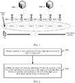
- FIG. 1 is a schematic diagram of a network architecture of a super cell.
- cell 1 to cell 6 are coverage cells that correspond to a base station and that are disposed along a high-speed railway.
- a distributed base station architecture for example, a distributed base station including a base band unit (Building Base band Unit, BBU) and a radio remote unit (Radio Remote Unit, RRU), may be used.
- BBU Building Base band Unit
- RRU Radio Remote Unit
- the BBU and the RRU are connected by using a fiber, and one BBU can support multiple RRUs.
- the BBU mainly performs functions such as baseband signal processing and transmission as well as functions of a master controller and a clock.
- the RRU mainly performs processing including radio frequency signal filtering, signal amplification, and up- and down-frequency conversion, and uses a digital intermediate frequency technology to convert an intermediate frequency analog signal into a baseband digital signal.
- the super cell is a technology based on a single frequency network (Single Frequency Network, SFN).
- SFN Single Frequency Network
- the SFN means that multiple radio transmitting stations at different places and in a synchronization state simultaneously transmit a same signal at a same frequency, to reliably cover a particular service area. Therefore, in the embodiments of the present invention, cells along a high-speed transportation line can also be based on the SFN. That is, a target cell and a neighboring cell in the embodiments of the present invention have to satisfy SFN characteristics such as co-frequency and clock synchronization.
- a network architecture in the embodiments of the present invention includes but is not merely limited to the foregoing network architecture, and each network architecture that can implement cell combination falls within the protection and coverage scope of the present invention.
- user equipment UE in the embodiments of the present invention includes but is not limited to communications devices such as a smartphone, a tablet computer, a media player, a smart TV, a smart band, a smart wearable device, an MP3 player (Moving Picture Experts Group Audio Layer III, Moving Picture Experts Group Audio Layer-3), an MP4 (Moving Picture Experts Group Audio Layer IV, Moving Picture Experts Group Audio Layer-4) player, a personal digital assistant (Personal Digital Assistant, PDA), a portable laptop computer, and a desktop computer that can communicate and interact with a base station or another network device.
- communications devices such as a smartphone, a tablet computer, a media player, a smart TV, a smart band, a smart wearable device, an MP3 player (Moving Picture Experts Group Audio Layer III, Moving Picture Experts Group Audio Layer-3), an MP4 (Moving Picture Experts Group Audio Layer IV, Moving Picture Experts Group Audio Layer-4) player, a personal digital assistant (Personal Digital Assistant, PDA), a portable laptop computer,
- Specific application scenarios of the embodiments of the present invention include but are not merely limited to highways, railroads, high-speed railways, tunnels, and the like.
- an application scenario of a high-speed railway is mainly used for detailed description and illustration.
- FIG. 2 is a schematic flowchart of a method for dynamically combining cells according to an embodiment of the present invention. A description is provided below from a perspective of a network device side with reference to FIG. 2 . As shown in FIG. 2 , the method may include the following step S201 and step S202.
- Step S201 Obtain a quantity of user equipments UEs in a high-speed movement state in a target cell.
- the target cell is capable of being combined with a neighboring cell of the target cell, and the target cell and the neighboring cell are cells distributed along a high-speed movement path, that is, in a line shape rather than a star shape, such as cells along a high-speed railway, cells along a highway, or cells along a railroad.
- the UEs in the high-speed movement state are UEs that are in a connected mode and whose movement speeds are greater than a preset threshold, for example, a UE making a call or a UE accessing the Internet or using an SMS message or another service on a high-speed railway whose driving speed reaches a particular value.
- the preset threshold may be properly set according to a practical application scenario. It should be noted that due to a train length, generally, a length of one train does not go beyond a coverage area of three cells. Generally, a coverage area of one cell is approximately 200 m, and a length of one train is approximately 300 m.
- each of the cells distributed along the high-speed movement path is a target cell, and the target cell is not limited to a particular cell. Therefore, in this embodiment of the present invention, the description provided from the perspective of the network device side may be understood as a description provided from a perspective of a network device side of each target cell, that is, a base station side corresponding to the target cell.
- a Doppler frequency offset of a UE under a high-speed driving condition changes to some degree. Therefore, whether a UE is a UE in the high-speed movement state whose movement speed is greater than the preset threshold may be determined by obtaining a Doppler frequency offset of the UE. Specifically, a Doppler frequency offset of a UE in a connected mode in the target cell is obtained; when it is determined that the Doppler frequency offset is greater than the preset threshold, the UE is determined as a UE in the high-speed movement state; a quantity of UEs determined to be in the high-speed movement state is calculated, thereby finally obtaining the quantity of the user equipments UEs in the high-speed movement state in the target cell.
- the UE is handed over from the neighboring cell of the target cell, so as to prevent a UE that quickly moves for a short time near the high-speed railway from being mistakenly determined as a UE in the high-speed movement state.
- a combined cell is a logical cell. Although physical cell identifiers (Physical Cell Identity, PCI) of the target cell and the neighboring cell are the same, respective independent cell global identifiers (Cell Global Identifier, CGI) are configured for the target cell and the neighboring cell. Therefore, a handover record may be obtained according to different CGIs of different cells accessed by the UE in the high-speed movement state.
- PCI Physical Cell Identity
- CGI Cell Global Identifier
- Step S202 Combine the target cell with the neighboring cell when the quantity of the UEs in the high-speed movement state in the target cell is greater than a first preset quantity, and send data to the UEs in the high-speed movement state by using a combined cell.
- a relationship between the quantity of the UEs in the high-speed movement state in the target cell and the first preset quantity is determined.
- the target cell and the neighboring cell are combined.
- the target cell and the neighboring cell have a linear relationship, that is, each target cell has two neighboring cells respectively at the left and right sides. Therefore, in this embodiment of the present invention, the target cell and the neighboring cell are combined, which means that the target cell is combined with both neighboring cells respectively at the left and right sides, or means that the target cell is combined with a neighboring cell that a train is about to head for.
- the combined cell may be considered as a logical cell.
- All cells in the combined cell cooperatively send the data to the UEs in the high-speed movement state, so that the UEs in the high-speed movement state do not require a cell handover in the combined cell.
- a cell in which the UEs in the high-speed movement state are currently located and a cell that the train is about to arrive at are combined in advance, so as to combine the cells before the train arrives at the cell. In this way, the train seems to be always in one logical cell when the train is driving, implementing no handover in the entire journey on the high-speed railway.
- a capacity of only the combined cell is reduced, and a cell that is not combined can still accommodate a terrestrial user and remain an original cell capacity, thereby increasing a capacity of cells along the high-speed transportation line, avoiding a capacity bottleneck caused in a super cell by combining all cells along the high-speed transportation line in the entire journey.
- the preset quantity is 0, provided that it is determined that the target cell includes a UE in the high-speed movement state, cell combination is triggered, so that the UE in the high-speed movement state enjoys a no-handover service in the entire journey on the high-speed railway after the cell combination.
- the combined cell may be regularly separated, periodically separated, or separated in response to a trigger.
- cells that have been combined may be separated in response to a trigger condition, to release a resource, thereby further increasing the capacity of the cells along the high-speed transportation line.
- a quantity of user equipments UEs in a high-speed movement state in a target cell is obtained; and the target cell is combined with a neighboring cell when it is determined that the quantity of the UEs in the high-speed movement state is greater than a first preset quantity, and data is sent to the UEs in the high-speed movement state by using a combined cell. That is, in this embodiment of the present invention, a busy/idle status of a cell is detected in real time, and cells are dynamically combined according to busy/idle statuses.
- the combined cell provides a no-handover service to the UEs in the high-speed movement state, and a cell that is not combined can still support a terrestrial user, that is, a UE in a low-speed movement state, resolving a problem in the prior art that a cell capacity is limited and a cell cannot support a terrestrial user because cells along a high-speed transportation line are used as one cell in the entire journey by means of a super cell, effectively increasing a capacity of the cells along the high-speed transportation line, and ensuring communication quality of the UEs in the high-speed movement state.
- the combined cell may be further dynamically separated, so as to release a resource when there are fewer UEs in the high-speed movement state, further increasing the capacity of the cells along the high-speed transportation line.
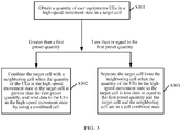
- FIG. 3 is a schematic flowchart of another method for dynamically combining cells according to an embodiment of the present invention. A description is provided below from a perspective of a network device side with reference to FIG. 3 . As shown in FIG. 3 , the method may include the following step S301 to step S303.
- Step S301 Obtain a quantity of user equipments UEs in a high-speed movement state in a target cell.
- Step S302 Combine the target cell with the neighboring cell when the quantity of the UEs in the high-speed movement state in the target cell is greater than a first preset quantity, and send data to the UEs in the high-speed movement state by using a combined cell.
- step S301 and step S302 refer to step S201 and step S202 in the embodiment in FIG. 2 . Details are not described herein again.
- Step S303 Separate the target cell from the neighboring cell when the quantity of the UEs in the high-speed movement state in the target cell is less than or equal to the first preset quantity and the target cell and the neighboring cell are in a cell combined state.
- step S303 may be performed after step S302, or may be performed before S202.
- an initial state between cells along a high-speed transportation line or between a target cell and a neighboring cell is a combined state.
- determining is performed by using a network device, for example, a base station, corresponding to each target cell.
- the target cell and the neighboring cell do not need to be in the combined state may be determined.
- the corresponding target cell and neighboring cell may be controlled to be separated, so as to release a cell resource and support an ordinary terrestrial user, that is, a UE in a low-speed movement state, thereby further increasing a capacity of the cells along the high-speed transportation line.
- a quantity of user equipments UEs in a high-speed movement state in a target cell is obtained; and the target cell is combined with a neighboring cell when it is determined that the quantity of the UEs in the high-speed movement state is greater than a first preset quantity, and data is sent to the UEs in the high-speed movement state by using a combined cell. That is, in this embodiment of the present invention, a busy/idle status of a cell is detected in real time, and cells are dynamically combined according to busy/idle statuses.
- the combined cell provides a no-handover service to the UEs in the high-speed movement state, and a cell that is not combined can still support a terrestrial user, that is, a UE in a low-speed movement state, resolving a problem in the prior art that a cell capacity is limited and a cell cannot support a terrestrial user because cells along a high-speed transportation line are used as one cell in the entire journey by means of a super cell, effectively increasing a capacity of the cells along the high-speed transportation line, and ensuring communication quality of the UEs in the high-speed movement state.
- the combined cell may be further dynamically separated, so as to release a resource when there are fewer UEs in the high-speed movement state, further increasing the capacity of the cells along the high-speed transportation line.
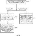
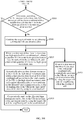
- FIG. 4 is a schematic flowchart of still another method for dynamically combining cells according to an embodiment of the present invention. A description is provided below from a perspective of a network device side with reference to FIG. 4 . As shown in FIG. 4 , the method may include the following step S401 to step S404.
- Step S401 Obtain a quantity of user equipments UEs in a high-speed movement state in a target cell.
- step S401 refers to step S201 in the embodiment in FIG. 2 . Details are not described herein again.
- Step S402 Determine a movement direction of the UEs in the high-speed movement state when the quantity of the UEs in the high-speed movement state in the target cell is greater than a first preset quantity.
- a trigger condition for cell combination is satisfied.
- the target cell has two neighboring cells respectively at the left and right sides, and one train can drive towards only one direction at a moment, if both of the neighboring cells are used for combination, a resource is wasted in a neighboring cell that the train does not arrive at. Therefore, a driving direction of the train needs to be determined, that is, a movement direction of user equipment on the train, that is, the UEs in the high-speed movement state, needs to be determined.
- the movement direction of the UEs in the high-speed movement state may be determined according to a cell handover history record or a cell combination history record of the UEs in the high-speed movement state.
- a cell handover history record of the UEs in the high-speed movement state may be obtained, and the movement direction of the UEs may be determined according to the cell handover history record.
- a unique identifier of a neighboring cell with which the target cell is combined last time may be obtained, and the movement direction of the UEs in the high-speed movement state may be determined and predicted according to a unique identifier of the target cell and the obtained unique identifier of the neighboring cell.
- the unique identifier is a numeric identifier that sequentially marks each cell along a high-speed transportation line.
- a cell handover history record or a cell combination history record of the UEs in the high-speed movement state may not be formed. Therefore, a situation in which there is no history record needs to be ignored, and the foregoing step of determining the movement direction can be performed only after the cell handover or cell combination history record of the UEs is generated.
- Step S403 Combine, according to the movement direction, the target cell with a neighboring cell that the UEs in the high-speed movement state are about to enter, and send data to the UEs in the high-speed movement state by using a combined cell.
- the target cell is combined with the neighboring cell that the UEs in the high-speed movement state are about to enter according to the movement direction determined in step S402.
- the combination may be implemented by changing respective physical cell identifiers PCIs of the target cell and the neighboring cell into a preset PCI together, and configuring a parameter for the target cell and the neighboring cell according to a preset cell combination rule.
- a switch that is mutually exclusive with a characteristic algorithm of a super cell may be disabled, and a fixed parameter of the combined cell is configured according to a requirement of the super cell.
- the preset PCI needs to be set in advance. That is, the preset PCI is always used for cell combination in the entire journey. Because a quantity of PCIs is limited, a rule specifying that the preset PCI is not the same as or does not conflict with PCIs of the cells along the high-speed transportation line needs to be satisfied. Otherwise, an error may occur in cell combination.
- Step S404 Separate the target cell from the neighboring cell when the quantity of the UEs in the high-speed movement state in the target cell is less than or equal to the first preset quantity and the target cell and the neighboring cell are in a cell combined state.
- the preset PCI into which the PCI of the target cell is changed is restored to a PCI that exists before the cell combination
- the parameter configured for the target cell according to the preset cell combination rule is restored to a parameter that exists before the cell combination. Further, both a related algorithm and the fixed parameter are restored to statuses that exist before the cell combination.
- a quantity of user equipments UEs in a high-speed movement state in a target cell is obtained; and the target cell is combined with a neighboring cell when it is determined that the quantity of the UEs in the high-speed movement state is greater than a first preset quantity, and data is sent to the UEs in the high-speed movement state by using a combined cell. That is, in this embodiment of the present invention, a busy/idle status of a cell is detected in real time, and cells are dynamically combined according to busy/idle statuses.
- the combined cell provides a no-handover service to the UEs in the high-speed movement state, and a cell that is not combined can still support a terrestrial user, that is, a UE in a low-speed movement state, resolving a problem in the prior art that a cell capacity is limited and a cell cannot support a terrestrial user because cells along a high-speed transportation line are used as one cell in the entire journey by means of a super cell, effectively increasing a capacity of the cells along the high-speed transportation line, and ensuring communication quality of the UEs in the high-speed movement state.
- the combined cell may be further dynamically separated, so as to release a resource when there are fewer UEs in the high-speed movement state, further increasing the capacity of the cells along the high-speed transportation line.
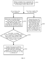
- FIG. 5 is a schematic flowchart of still another method for dynamically combining cells according to an embodiment of the present invention. A description is provided below from a perspective of a network device side with reference to FIG. 5 . As shown in FIG. 5 , the method may include the following step S501 to step S505.
- Step S501 Obtain a quantity of user equipments UEs in a high-speed movement state in a target cell according to a preset time interval.
- the quantity of the UEs in the high-speed movement state in the target cell is obtained in real time or is periodically obtained according to the preset time interval, so as to circularly and coherently perform the following step of cell combination or cell separation in this embodiment of the present invention.
- the preset time interval may be correspondingly adjusted according to different application scenarios, or may be dynamically adjusted with reference to a railroad train schedule. For example, during busy time, the preset time interval is adjusted shorter; during idle time, the preset time interval may be properly adjusted longer, to better save expenses. More specifically, refer to step S201 in the embodiment in FIG. 2 . Details are not described herein again.
- Step S502 Determine a movement direction of the UEs in the high-speed movement state when the quantity of the UEs in the high-speed movement state in the target cell is greater than a first preset quantity.
- step S502 refers to step S402 in the embodiment in FIG. 4 . Details are not described herein again.
- Step S503 Determine, according to the movement direction, whether the target cell has been combined with a neighboring cell that the UEs in the high-speed movement state are about to enter.
- whether the target cell has been combined with the neighboring cell that the UEs in the high-speed movement state are about to enter is specifically determined according to the movement direction. If the two cells have been combined, the following step of cell combination is not performed.
- Step S504 Combine the target cell with the neighboring cell that the UEs are about to enter if the two cells are not combined, and send data to the UEs in the high-speed movement state by using a combined cell.
- the target cell is combined, according to the movement direction determined in step S502, with the neighboring cell that the UEs are about to enter. More specifically, refer to step S403 in the embodiment in FIG. 4 . Details are not described herein again.
- Step S505 Separate the target cell from the neighboring cell when the quantity of the UEs in the high-speed movement state in the target cell is less than or equal to the first preset quantity and the target cell and the neighboring cell are in a cell combined state.
- step S505 refers to step S404 in the embodiment in FIG. 4 . Details are not described herein again.
- a quantity of user equipments UEs in a high-speed movement state in a target cell is obtained; and the target cell is combined with a neighboring cell when it is determined that the quantity of the UEs in the high-speed movement state is greater than a first preset quantity, and data is sent to the UEs in the high-speed movement state by using a combined cell. That is, in this embodiment of the present invention, a busy/idle status of a cell is detected in real time, and cells are dynamically combined according to busy/idle statuses.
- the combined cell provides a no-handover service to the UEs in the high-speed movement state, and a cell that is not combined can still support a terrestrial user, that is, a UE in a low-speed movement state, resolving a problem in the prior art that a cell capacity is limited and a cell cannot support a terrestrial user because cells along a high-speed transportation line are used as one cell in the entire journey by means of a super cell, effectively increasing a capacity of the cells along the high-speed transportation line, and ensuring communication quality of the UEs in the high-speed movement state.
- the combined cell may be further dynamically separated, so as to release a resource when there are fewer UEs in the high-speed movement state, further increasing the capacity of the cells along the high-speed transportation line.
- FIG. 6 is a schematic flowchart of still another method for dynamically combining cells according to an embodiment of the present invention. A description is provided below from a perspective of a network device side with reference to FIG. 6 . As shown in FIG. 6 , the method may include the following step S601 to step S608.
- Step S601 Obtain a quantity of user equipments UEs in a high-speed movement state in a target cell according to a preset time interval.
- step S601 refers to step S501 in the embodiment in FIG. 5 . Details are not described herein again.
- Step S602 Detect whether the target cell includes a UE in a low-speed movement state when the quantity of the UEs in the high-speed movement state in the target cell is greater than a first preset quantity.
- whether the target cell includes a UE in a low-speed movement state is detected when the quantity of the UEs in the high-speed movement state in the target cell is greater than the first preset quantity.
- the UE in the low-speed movement state is a UE that is in a connected mode and whose movement speed is less than a preset threshold. More specifically, for a method for determining whether a UE is in the low-speed movement state, correspondingly refer to the method for determining the speed of the UE in the connected mode in step S201 in the embodiment in FIG. 2 . Details are not described herein again.
- Step S603 If the target cell includes the UE in the low-speed movement state, hand over the UE in the low-speed movement state to the first carrier frequency to perform data transmission and receiving, and hand over the UEs in the high-speed movement state to the second carrier frequency to perform data transmission and receiving.
- both the target cell and the neighboring cell support the first carrier frequency and the second carrier frequency. That is, both the target cell and the neighboring cell are dual-carrier-frequency coverage cells, and data transmission and receiving on the first carrier frequency and data transmission and receiving on the second carrier frequency do not affect each other.
- a terrestrial user in a combined cell that is, a UE in the low-speed movement state may be not affected by the combined cell, and perform data transmission and receiving still in a transmission mode before the cell combination.
- a cell that is not combined can support a terrestrial user, that is, a UE in the low-speed movement state; in addition, because transmission of the UEs in the high-speed movement state and transmission of the UE in the low-speed movement state do not interfere with each other by handing over the UE in the low-speed movement state to a carrier frequency different from that of the UEs in the high-speed movement state, the combined cell can support both the UEs in the high-speed movement state and the UE in the low-speed movement state. That is, all cells along an entire high-speed transportation line can support both the UEs in the high-speed movement state and the UE in the low-speed movement state in after step S603 is performed.
- Step S604 Determine a movement direction of the UEs in the high-speed movement state.
- Step S605 Determine, according to the movement direction, whether the target cell has been combined with a neighboring cell that the UEs in the high-speed movement state are about to enter.
- Step S606 Combine the target cell with the neighboring cell that the UEs are about to enter if the two cells are not combined, and send data to the UEs in the high-speed movement state by using a combined cell.
- Step S607 Separate the target cell from the neighboring cell when the quantity of the UEs in the high-speed movement state in the target cell is less than or equal to the first preset quantity and the target cell and the neighboring cell are in a cell combined state.
- step S604 to step S607 refer to step S502 to step S505 in the embodiment in FIG. 5 . Details are not described herein again.
- Step S608 When it is determined that there is a UE in the low-speed movement state on the first carrier frequency for the target cell, hand over at least one UE in the low-speed movement state to the second carrier frequency to perform data transmission and receiving.
- the combined cell satisfies a cell separation condition and is separated.
- the second carrier frequency for the target cell is in an idle state, and some users performing data transmission and receiving on the first carrier frequency may be handed over to the second carrier frequency, to reduce load on the first carrier frequency and make full use of a carrier frequency resource.
- a quantity of user equipments UEs in a high-speed movement state in a target cell is obtained; and the target cell is combined with a neighboring cell when it is determined that the quantity of the UEs in the high-speed movement state is greater than a first preset quantity, and data is sent to the UEs in the high-speed movement state by using a combined cell. That is, in this embodiment of the present invention, a busy/idle status of a cell is detected in real time, and cells are dynamically combined according to busy/idle statuses.
- the combined cell provides a no-handover service to the UEs in the high-speed movement state, and a cell that is not combined can still support a terrestrial user, that is, a UE in a low-speed movement state, resolving a problem in the prior art that a cell capacity is limited and a cell cannot support a terrestrial user because cells along a high-speed transportation line are used as one cell in the entire journey by means of a super cell, effectively increasing a capacity of the cells along the high-speed transportation line, and ensuring communication quality of the UEs in the high-speed movement state.
- the combined cell may be further dynamically separated, so as to release a resource when there are fewer UEs in the high-speed movement state, further increasing the capacity of the cells along the high-speed transportation line.
- FIG. 7 is a schematic flowchart of still another method for dynamically combining cells according to an embodiment of the present invention. A description is provided below from a perspective of a network device side with reference to FIG. 7 . As shown in FIG. 7 , the method may include the following step S701 to step S708.
- Step S701 Obtain a quantity of user equipments UEs in a high-speed movement state in a target cell according to a preset time interval.
- Step S702 Detect whether the target cell includes a UE in a low-speed movement state when the quantity of the UEs in the high-speed movement state in the target cell is greater than a first preset quantity.
- Step S703 If the target cell includes the UE in the low-speed movement state, hand over the UE in the low-speed movement state to the first carrier frequency to perform data transmission and receiving, and hand over the UEs in the high-speed movement state to the second carrier frequency to perform data transmission and receiving.
- Step S704 Determine a movement direction of the UEs in the high-speed movement state.
- Step S705 Determine, according to the movement direction, whether the target cell has been combined with a neighboring cell that the UEs in the high-speed movement state are about to enter.
- step S701 to step S705 refer to step S601 to step S605 in the embodiment in FIG. 6 . Details are not described herein again.
- Step S706 Combine the target cell with the neighboring cell that the UEs are about to enter if the two cells are not combined, and cooperatively send data to the UEs in the high-speed movement state by using the target cell and the neighboring cell in a combined cell.
- the target cell is combined with the neighboring cell that the UEs are about to enter if a determining result in step S705 is that the two cells are not combined, and the data is cooperatively sent to the UEs in the high-speed movement state by using the target cell and the neighboring cell in the combined cell.
- the cooperatively sending data to the UEs in the high-speed movement state means sending the data to the UEs in the high-speed movement state in a coordinated multipoint (Coordinated Multiple Point, CoMP) transmission mode.
- CoMP Coordinatd Multiple Point
- antennas of multiple cell sites including a target cell and a neighboring cell perform receiving or transmission in a coordinated manner, to improve received signal quality of a UE or a network device, thereby implementing no handover of the UE in a combined cell.
- Step S707 Separate the target cell from the neighboring cell when the quantity of the UEs in the high-speed movement state in the target cell is less than or equal to the first preset quantity and the target cell and the neighboring cell are in a cell combined state.
- Step S708 When it is determined that there is a UE in the low-speed movement state on the first carrier frequency for the target cell, hand over at least one UE in the low-speed movement state to the second carrier frequency to perform data transmission and receiving.
- step S707 and step S708 refer to step S607 and step S608 in the embodiment in FIG. 6 . Details are not described herein again.
- a quantity of user equipments UEs in a high-speed movement state in a target cell is obtained; and the target cell is combined with a neighboring cell when it is determined that the quantity of the UEs in the high-speed movement state is greater than a first preset quantity, and data is sent to the UEs in the high-speed movement state by using a combined cell. That is, in this embodiment of the present invention, a busy/idle status of a cell is detected in real time, and cells are dynamically combined according to busy/idle statuses.
- the combined cell provides a no-handover service to the UEs in the high-speed movement state, and a cell that is not combined can still support a terrestrial user, that is, a UE in a low-speed movement state, resolving a problem in the prior art that a cell capacity is limited and a cell cannot support a terrestrial user because cells along a high-speed transportation line are used as one cell in the entire journey by means of a super cell, effectively increasing a capacity of the cells along the high-speed transportation line, and ensuring communication quality of the UEs in the high-speed movement state.
- the combined cell may be further dynamically separated, so as to release a resource when there are fewer UEs in the high-speed movement state, further increasing the capacity of the cells along the high-speed transportation line.
- FIG. 8A and FIG. 8B are a schematic flowchart of still another method for dynamically combining cells according to an embodiment of the present invention. A description is provided below from a perspective of a network device side with reference to FIG. 8A and FIG. 8B . As shown in FIG. 8A and FIG. 8B , the method may include the following step S801 to step S812.
- Step S801 Obtain a quantity of user equipments UEs in a high-speed movement state in a target cell according to a preset time interval.
- Step S802 Detect whether the target cell includes a UE in a low-speed movement state when the quantity of the UEs in the high-speed movement state in the target cell is greater than a first preset quantity.
- Step S803 If the target cell includes the UE in the low-speed movement state, hand over the UE in the low-speed movement state to the first carrier frequency to perform data transmission and receiving, and hand over the UEs in the high-speed movement state to the second carrier frequency to perform data transmission and receiving.
- Step S804 Determine a movement direction of the UEs in the high-speed movement state.
- Step S805 Determine, according to the movement direction, whether the target cell has been combined with a neighboring cell that the UEs in the high-speed movement state are about to enter.
- Step S806 Combine the target cell with the neighboring cell that the UEs are about to enter if the two cells are not combined.
- step S801 to step S806 refer to step S701 to step S706 in the embodiment in FIG. 7 . Details are not described herein again.
- Step S807 Determine whether the target cell and the neighboring cell in a combined cell are co-site cells.
- IP radio access network IP Radio Access Network
- IPRAN IP Radio Access Network
- a transmission delay corresponding to the networking is relatively large, and problems such as a data transmission error and a cell handover failure are caused when data cannot be synchronously sent to the UEs in the high-speed movement state by using the target cell and the neighboring cell in the combined cell. Therefore, in a process of sending the data to the UEs in the high-speed movement state by using the combined cell, a delay factor should be fully considered.
- cells of different sites have a relatively large data transmission delay, whether the target cell and the neighboring cell are co-site cells needs to be determined.
- cells corresponding to RRUs of different BBUs are cells of different sites, and different cells corresponding to RRUs of one BBU are co-site cells.
- this embodiment of the present invention is not limited to the IPRAN networking, and for any networking requiring a relatively large transmission delay or requiring considering a delay factor during data transmission, the steps of the method in this embodiment of the present invention may be performed.
- Step S808 Synchronously send data to the UEs in the high-speed movement state by using the target cell and the neighboring cell if the two cells are co-site cells.
- the data may be synchronously sent to the UEs in the high-speed movement state by using the target cell and the neighboring cell. More specifically, refer to step S706 in the embodiment in FIG. 7 . Details are not described herein again.
- Step S809 Obtain information about a transmission delay between the target cell and the neighboring cell if the two cells are not co-site cells.
- Step S810 Synchronously send data to the UEs in the high-speed movement state by using the target cell and the neighboring cell after a corresponding time is delayed in the target cell according to the information about the transmission delay.
- the delay time obtained in step S809 can be delayed in the target cell, and the data is synchronously sent to the UEs in the high-speed movement state by using the target cell and the neighboring cell.
- Step S811 Separate the target cell from the neighboring cell when the quantity of the UEs in the high-speed movement state in the target cell is less than or equal to the first preset quantity and the target cell and the neighboring cell are in a cell combined state.
- Step S812 When it is determined that there is a UE in the low-speed movement state on the first carrier frequency for the target cell, hand over at least one UE in the low-speed movement state to the second carrier frequency to perform data transmission and receiving.
- step S811 and step S812 refer to step S707 and step S708 in the embodiment in FIG. 7 . Details are not described herein again.
- a quantity of user equipments UEs in a high-speed movement state in a target cell is obtained; and the target cell is combined with a neighboring cell when it is determined that the quantity of the UEs in the high-speed movement state is greater than a first preset quantity, and data is sent to the UEs in the high-speed movement state by using a combined cell. That is, in this embodiment of the present invention, a busy/idle status of a cell is detected in real time, and cells are dynamically combined according to busy/idle statuses.
- the combined cell provides a no-handover service to the UEs in the high-speed movement state, and a cell that is not combined can still support a terrestrial user, that is, a UE in a low-speed movement state, resolving a problem in the prior art that a cell capacity is limited and a cell cannot support a terrestrial user because cells along a high-speed transportation line are used as one cell in the entire journey by means of a super cell, effectively increasing a capacity of the cells along the high-speed transportation line, and ensuring communication quality of the UEs in the high-speed movement state.
- the combined cell may be further dynamically separated, so as to release a resource when there are fewer UEs in the high-speed movement state, further increasing the capacity of the cells along the high-speed transportation line.
- FIG. 9A and FIG. 9B are a schematic flowchart of still another method for dynamically combining cells according to an embodiment of the present invention. A description is provided below from a perspective of a network device side with reference to FIG. 9A and FIG. 9B . As shown in FIG. 9A and FIG. 9B , the method may include the following step S901 to step S912.
- Step S901 Obtain a quantity of user equipments UEs in a high-speed movement state in a target cell according to a preset time interval.
- Step S902 Detect whether the target cell includes a UE in a low-speed movement state when the quantity of the UEs in the high-speed movement state in the target cell is greater than a first preset quantity.
- Step S903 If the target cell includes the UE in the low-speed movement state, hand over the UE in the low-speed movement state to the first carrier frequency to perform data transmission and receiving, and hand over the UEs in the high-speed movement state to the second carrier frequency to perform data transmission and receiving.
- Step S904 Determine a movement direction of the UEs in the high-speed movement state.
- Step S905 Determine, according to the movement direction, whether the target cell has been combined with a neighboring cell that the UEs in the high-speed movement state are about to enter.
- Step S906 Combine the target cell with the neighboring cell that the UEs are about to enter if the two cells are not combined.
- step S901 to step S906 refer to step S801 to step S806 in the embodiment in FIG. 8A and FIG. 8B . Details are not described herein again.
- Step S907 When it is determined that there is more than one high-speed cell in a combined cell, obtain a quantity of UEs in the high-speed movement state in each cell in the combined cell, and count a total quantity of UEs in the high-speed movement state.
- the high-speed cell is a cell, in the combined cell, in which a quantity of UEs in the high-speed movement state is greater than a second preset quantity. All cells in the combined cell need to simultaneously send same data to a same UE, but a cell in the combined cell cannot learn existence of a UE in the high-speed movement state in another cell that is determined as a high-speed cell.
- a train is within a coverage area of multiple cells at a moment, and more than one cell includes a quantity of UEs that are in the high-speed movement state, where the quantity is greater than the second preset quantity
- a conflict in allocating a channel resource for example, a conflict between a physical downlink control channel (Physical Downlink Control Channel, PDCCH) and a physical downlink shared channel (Physical Downlink Shared Channel, PDSCH).
- PDCCH Physical Downlink Control Channel
- PDSCH Physical Downlink Shared Channel
- each cell in the combined cell may be instructed to collect statistics on a quantity of UEs in the high-speed movement state in the cell, and to report the quantity to a preset network device together, for example, report the quantity to a network device corresponding to a cell with a maximum or minimum cell CGI, so as to count a total quantity.
- the second preset quantity is 0.
- Step S908 Dynamically allocate time domain resources to the UEs in the high-speed movement state within a transmission time interval TTI of the combined cell according to the total quantity of the UEs in the high-speed movement state and a preset allocation rule, so as to perform, on the allocated time domain resources, a step of sending data to the UEs in the high-speed movement state by using the combined cell.
- the time domain resources are dynamically allocated to the UEs in the high-speed movement state within the TTI according to the total quantity of the UEs in the high-speed movement state that is counted in step S907, the transmission time interval (Transmission Time Interval, TTI) of the combined cell, and the preset allocation rule.
- the time domain resources are allocated according to a rule such as preferably allocating a resource to a cell including more UEs in the high-speed movement state or allocating resources in sequence according to values of unique identifiers of cells. In this way, the step of sending data to the UEs in the high-speed movement state by using the combined cell is performed on the allocated time domain resources.
- Step S909 Cooperatively send, on the allocated time domain resources, data to the UEs in the high-speed movement state by using the target cell and the neighboring cell in the combined cell. Specifically, the data is cooperatively sent, on the time domain resources allocated in step S908, to the UEs in the high-speed movement state by using the target cell and the neighboring cell in the combined cell. More specifically, refer to step S706 in the embodiment in FIG. 7 . Details are not described herein again.
- Step S910 When it is determined that there is one high-speed cell in the combined cell, cooperatively send data to the UEs in the high-speed movement state by using the target cell and the neighboring cell in the combined cell.
- step S910 refers to step S706 in the embodiment in FIG. 7 . Details are not described herein again.
- Step S911 Separate the target cell from the neighboring cell when the quantity of the UEs in the high-speed movement state in the target cell is less than or equal to the first preset quantity and the target cell and the neighboring cell are in a cell combined state.
- Step S912 When it is determined that there is a UE in the low-speed movement state on the first carrier frequency for the target cell, hand over at least one UE in the low-speed movement state to the second carrier frequency to perform data transmission and receiving.
- step S911 and step S912 refer to step S811 and step S812 in the embodiment in FIG. 8A and FIG. 8B . Details are not described herein again.
- a quantity of user equipments UEs in a high-speed movement state in a target cell is obtained; and the target cell is combined with a neighboring cell when it is determined that the quantity of the UEs in the high-speed movement state is greater than a first preset quantity, and data is sent to the UEs in the high-speed movement state by using a combined cell. That is, in this embodiment of the present invention, a busy/idle status of a cell is detected in real time, and cells are dynamically combined according to busy/idle statuses.
- the combined cell provides a no-handover service to the UEs in the high-speed movement state, and a cell that is not combined can still support a terrestrial user, that is, a UE in a low-speed movement state, resolving a problem in the prior art that a cell capacity is limited and a cell cannot support a terrestrial user because cells along a high-speed transportation line are used as one cell in the entire journey by means of a super cell, effectively increasing a capacity of the cells along the high-speed transportation line, and ensuring communication quality of the UEs in the high-speed movement state.
- the combined cell may be further dynamically separated, so as to release a resource when there are fewer UEs in the high-speed movement state, further increasing the capacity of the cells along the high-speed transportation line.
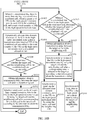
- FIG. 10A and FIG. 10B are a schematic flowchart of still another method for dynamically combining cells according to an embodiment of the present invention. A description is provided below from a perspective of a network device side with reference to FIG. 10A and FIG. 10B . As shown in FIG. 10A and FIG. 10B , the method may include the following step S1001 to step S1018.
- Step S1001 Obtain a quantity of user equipments UEs in a high-speed movement state in a target cell according to a preset time interval.
- Step S1002 Detect whether the target cell includes a UE in a low-speed movement state when the quantity of the UEs in the high-speed movement state in the target cell is greater than a first preset quantity.
- Step S1003 If the target cell includes the UE in the low-speed movement state, hand over the UE in the low-speed movement state to the first carrier frequency to perform data transmission and receiving, and hand over the UEs in the high-speed movement state to the second carrier frequency to perform data transmission and receiving.
- Step S1004 Determine a movement direction of the UEs in the high-speed movement state.
- Step S1005 Determine, according to the movement direction, whether the target cell has been combined with a neighboring cell that the UEs in the high-speed movement state are about to enter.
- Step S1006 Combine the target cell with the neighboring cell that the UEs are about to enter if the two cells are not combined.
- Step S1007 When it is determined that there is more than one high-speed cell in a combined cell, obtain a quantity of UEs in the high-speed movement state in each cell in the combined cell, and count a total quantity of UEs in the high-speed movement state.
- Step S1008 Dynamically allocate time domain resources to the UEs in the high-speed movement state within a transmission time interval TTI of the combined cell according to the total quantity of the UEs in the high-speed movement state and a preset allocation rule. Specifically, for step S1001 to step S1008, refer to step S901 to step S908 in the embodiment in FIG. 9A and FIG. 9B . Details are not described herein again.
- Step S1009 Determine whether the target cell and the neighboring cell in the combined cell are co-site cells.
- Step S1010 Synchronously send, on the allocated time domain resources, data to the UEs in the high-speed movement state by using the target cell and the neighboring cell if the two cells are co-site cells.
- Step S1011 Obtain information about a transmission delay between the target cell and the neighboring cell if the two cells are not co-site cells.
- Step S1012 Synchronously send, on the allocated time domain resources, data to the UEs in the high-speed movement state by using the target cell and the neighboring cell after a corresponding time is delayed in the target cell according to the information about the transmission delay.
- step S1009 to step S1012 refer to step S807 to step S810 in the embodiment in FIG. 8A and FIG. 8B . Details are not described herein again.
- Step S1013 When it is determined that there is one high-speed cell in the combined cell, determine whether the target cell and the neighboring cell in the combined cell are co-site cells.
- Step S1014 Synchronously send data to the UEs in the high-speed movement state by using the target cell and the neighboring cell if the two cells are co-site cells.
- Step S1015 Obtain information about a transmission delay between the target cell and the neighboring cell if the two cells are not co-site cells.
- Step S1016 Synchronously send data to the UEs in the high-speed movement state by using the target cell and the neighboring cell after a corresponding time is delayed in the target cell according to the information about the transmission delay.
- step S1013 to step S1016 refer to step S807 to step S810 in the embodiment in FIG. 8A and FIG. 8B . Details are not described herein again.
- Step S1017 Separate the target cell from the neighboring cell when the quantity of the UEs in the high-speed movement state in the target cell is less than or equal to the first preset quantity and the target cell and the neighboring cell are in a cell combined state.
- Step S1018 When it is determined that there is a UE in the low-speed movement state on the first carrier frequency for the target cell, hand over at least one UE in the low-speed movement state to the second carrier frequency to perform data transmission and receiving.
- step S1017 and step S1018 refer to step S911 and step S912 in the embodiment in FIG. 9A and FIG. 9B . Details are not described herein again.
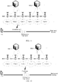
- FIG. 11 and FIG. 12 are schematic diagrams of a specific application scenario of a method for dynamically combining cells according to an embodiment of the present invention.
- a target cell cell 2 includes more UEs in a high-speed movement state, and in this case, a driving direction of a train is from left to right in the figure. Therefore, cell 2 and cell 3 are combined.
- FIG. 11 a target cell cell 2 includes more UEs in a high-speed movement state, and in this case, a driving direction of a train is from left to right in the figure. Therefore, cell 2 and cell 3 are combined.
- the train arrives at cell 3, and when detecting that a quantity of UEs in the high-speed movement state in cell 3 is greater than a particular quantity, a network device corresponding to the target cell cell 3 at this moment learns a direction of the train according to a cell handover record or cell combination record of the UEs in the high-speed movement state, and combines cell 3 and cell 4.
- a network device corresponding to the target cell cell 3 at this moment learns a direction of the train according to a cell handover record or cell combination record of the UEs in the high-speed movement state, and combines cell 3 and cell 4.
- FIG. 13 and FIG. 14 are schematic diagrams of another specific application scenario of a method for dynamically combining cells according to an embodiment of the present invention.
- both a target cell cell 2 and a target cell cell 6 include more UEs in a high-speed movement state. That is, in this case, two trains drive from different directions. One train from left to right is in cell 2, and cell 2 and cell 3 are combined; the other train from right to left is in cell 6, and cell 5 and cell 6 are combined. It can be predicted that in a next time period, a scenario in FIG. 14 appears. That is, two cells obtained through combination get closer to the middle.
- cell 2, cell 3, cell 4, cell 5, and cell 6 are combined to form a combined cell.
- Multiple cells in the combined cell include a UE in the high-speed movement state, and there are cells of different sites.
- time domain resources need to be coordinately allocated, and delay information needs to be calculated for synchronous data sending.
- a quantity of user equipments UEs in a high-speed movement state in a target cell is obtained; and the target cell is combined with a neighboring cell when it is determined that the quantity of the UEs in the high-speed movement state is greater than a first preset quantity, and data is sent to the UEs in the high-speed movement state by using a combined cell. That is, in this embodiment of the present invention, a busy/idle status of a cell is detected in real time, and cells are dynamically combined according to busy/idle statuses.
- the combined cell provides a no-handover service to the UEs in the high-speed movement state, and a cell that is not combined can still support a terrestrial user, that is, a UE in a low-speed movement state, resolving a problem in the prior art that a cell capacity is limited and a cell cannot support a terrestrial user because cells along a high-speed transportation line are used as one cell in the entire journey by means of a super cell, effectively increasing a capacity of the cells along the high-speed transportation line, and ensuring communication quality of the UEs in the high-speed movement state.
- the combined cell may be further dynamically separated, so as to release a resource when there are fewer UEs in the high-speed movement state, further increasing the capacity of the cells along the high-speed transportation line.
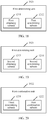
- the apparatus 10 may include an obtaining module 101, a combination module 102, and a sending module 103.
- the obtaining module 101 is configured to obtain a quantity of user equipments UEs in a high-speed movement state in a target cell.
- the target cell is capable of being combined with a neighboring cell of the target cell, the target cell and the neighboring cell are cells distributed along a high-speed movement path, and the UEs in the high-speed movement state are UEs that are in a connected mode and whose movement speeds are greater than a preset threshold.
- the combination module 102 is configured to combine the target cell with the neighboring cell when the quantity of the UEs in the high-speed movement state in the target cell is greater than a first preset quantity.
- the sending module 103 is configured to send data to the UEs in the high-speed movement state by using a combined cell.
- FIG. 16 is a schematic structural diagram of another embodiment of an apparatus for dynamically combining cells according to the present invention.
- the apparatus for dynamically combining cells may further include a first separation module 104.
- the first separation module 104 is configured to separate the target cell from the neighboring cell when the quantity of the UEs in the high-speed movement state in the target cell is less than or equal to the first preset quantity and the target cell and the neighboring cell are in a cell combined state.
- FIG. 17 is a schematic structural diagram of another embodiment of a combination module according to the present invention.
- the combination module 102 may include a first determining unit 1021 and a first combination unit 1022.
- the first determining unit 1021 is configured to determine a movement direction of the UEs in the high-speed movement state when the quantity of the UEs in the high-speed movement state in the target cell is greater than the first preset quantity.
- the first combination unit 1022 is configured to combine, according to the movement direction, the target cell with a neighboring cell that the UEs in the high-speed movement state are about to enter.
- FIG. 18 is a schematic structural diagram of another embodiment of a first determining unit according to the present invention.
- the first determining unit 1021 may include a first obtaining subunit 1211 and a first determining subunit 1212.
- the first obtaining subunit 1211 is configured to obtain a cell handover history record of the UEs in the high-speed movement state.
- the first determining subunit 1212 is configured to determine the movement direction of the UEs in the high-speed movement state according to the cell handover history record.
- FIG. 19 is a schematic structural diagram of still another embodiment of a first determining unit according to the present invention.
- the first determining unit may include a second obtaining subunit 1213 and a second determining subunit 1214.
- the second obtaining subunit 1213 is configured to obtain a unique identifier of a neighboring cell with which the target cell is combined last time.
- the unique identifier is a numeric identifier that sequentially marks the cell distributed along the high-speed movement path.
- the second determining subunit 1214 is configured to determine and predict the movement direction of the UEs in the high-speed movement state according to a unique identifier of the target cell and the obtained unique identifier of the neighboring cell.
- FIG. 20 is a schematic structural diagram of another embodiment of a first combination unit according to the present invention.
- the obtaining module 101 is specifically configured to perform the step of obtaining a quantity of user equipments UEs in a high-speed movement state in a target cell according to a preset time interval.
- the first combination unit 1022 may include a third determining subunit 1221 and a first combination subunit 1222.
- the third determining subunit 1221 is configured to determine, according to the movement direction, whether the target cell has been combined with the neighboring cell that the UEs in the high-speed movement state are about to enter.
- the first combination subunit 1222 is configured to combine the target cell with the neighboring cell that the UEs are about to enter if the two cells are not combined.
- FIG. 21 is a schematic structural diagram of still another embodiment of a combination module according to the present invention. Both the target cell and the neighboring cell support a first carrier frequency and a second carrier frequency.
- the combination module 102 may include a detection unit 1023, a handover unit 1024, and a second combination unit 1025.
- the detection unit 1023 is configured to detect whether the target cell includes a UE in a low-speed movement state when the quantity of the UEs in the high-speed movement state in the target cell is greater than the first preset quantity, where the UE in the low-speed movement state is a UE that is in a connected mode and whose movement speed is less than the preset threshold.
- the handover unit 1024 is configured to: if a determining result is that the target cell includes the UE in the low-speed movement state, hand over the UE in the low-speed movement state to the first carrier frequency to perform data transmission and receiving, and hand over the UEs in the high-speed movement state to the second carrier frequency to perform data transmission and receiving.
- the second combination unit 1025 is configured to combine the target cell with the neighboring cell.
- FIG. 22 is a schematic structural diagram of still another embodiment of an apparatus for dynamically combining cells according to the present invention.
- the apparatus 10 for dynamically combining cells may further include a second separation module 105 and a handover module 106.
- the second separation module 105 is configured to separate the target cell from the neighboring cell when the quantity of the UEs in the high-speed movement state in the target cell is less than or equal to the first preset quantity and the target cell and the neighboring cell are in a cell combined state.
- the handover module 106 is configured to: when it is determined that there is a UE in the low-speed movement state on the first carrier frequency for the target cell, hand over at least one UE in the low-speed movement state to the second carrier frequency to perform data transmission and receiving.
- FIG. 23 is a schematic structural diagram of still another embodiment of a combination module according to the present invention.
- the combination module 102 may include a changing unit 1026 and a configuration unit 1027.
- the changing unit 1026 is configured to change respective physical cell identifiers PCIs of the target cell and the neighboring cell into a preset PCI when the quantity of the UEs in the high-speed movement state in the target cell is greater than the first preset quantity.
- the configuration unit 1027 is configured to configure a parameter for the target cell and the neighboring cell according to a preset cell combination rule.
- FIG. 24 is a schematic structural diagram of still another embodiment of an apparatus for dynamically combining cells according to the present invention.
- the apparatus 10 for dynamically combining cells may further include a first restoration module 107 and a second restoration module 108.
- the first restoration module 107 is configured to: when the quantity of the UEs in the high-speed movement state in the target cell is less than or equal to the first preset quantity and the target cell and the neighboring cell are in the cell combined state, restore the preset PCI into which the PCI of the target cell is changed to a PCI that exists before the cell combination.
- the second restoration module 108 is configured to restore the parameter configured for the target cell according to the preset cell combination rule to a parameter that exists before the cell combination.
- the sending module 103 is specifically configured to:
- FIG. 25 is a schematic structural diagram of another embodiment of a sending module according to the present invention.
- Cells along a high-speed transportation line use IP radio access network IPRAN networking.
- the sending module 103 may further include a second determining unit 1031, a first synchronization unit 1032, a second obtaining unit 1033, and a second synchronization unit 1034.
- the second determining unit 1031 is configured to determine whether the target cell and the neighboring cell in the combined cell are co-site cells.
- the first synchronization unit 1032 is configured to synchronously send the data to the UEs in the high-speed movement state by using the target cell and the neighboring cell if a determining result is that the two cells are co-site cells.
- the second obtaining unit 1033 is configured to obtain information about a transmission delay between the target cell and the neighboring cell if a determining result is that the two cells are not co-site cells.
- the second synchronization unit 1034 is configured to synchronously send the data to the UEs in the high-speed movement state by using the target cell and the neighboring cell after a corresponding time is delayed in the target cell according to the information about the transmission delay.
- FIG. 26 is a schematic structural diagram of still another embodiment of an apparatus for dynamically combining cells according to the present invention.
- the apparatus may further include a counting module 109 and an allocation module 110.
- the counting module 109 is configured to: when it is determined that there is more than one high-speed cell in the combined cell, obtain a quantity of UEs in the high-speed movement state in each cell in the combined cell, and count a total quantity of UEs in the high-speed movement state, where the high-speed cell is a cell, in the combined cell, in which a quantity of UEs in the high-speed movement state is greater than a second preset quantity.
- the allocation module 110 is configured to dynamically allocate time domain resources to the UEs in the high-speed movement state within a transmission time interval TTI of the combined cell according to the total quantity of the UEs in the high-speed movement state and a preset allocation rule, so as to perform, on the allocated time domain resources, the step of sending data to the UEs in the high-speed movement state by using a combined cell.
- the present invention further provides a related device configured to cooperatively implement the foregoing solutions.
- a related device configured to cooperatively implement the foregoing solutions.
- FIG. 27 Detailed descriptions are provided below with reference to a schematic structural diagram of an embodiment of a network device according to the present invention shown in FIG. 27 .
- the network device 20 includes an input apparatus 201, an output apparatus 202, a memory 203, and a processor 204 (the network device 20 may include one or more processors 204, and in FIG. 27 , one processor is used as an example).
- the input apparatus 201, the output apparatus 202, the memory 203, and the processor 204 may be connected by using a bus or in another manner. In FIG. 27 , an example in which connection is implemented by using a bus is used.
- the memory 203 is configured to store program code.
- the processor 204 is configured to invoke the program code stored in the memory 203 to perform the following steps:
- the method further includes:
- that the processor 204 combines the target cell with the neighboring cell includes:
- the processor 204 determines a movement direction of the UEs in the high-speed movement state includes:
- the processor 204 determines a movement direction of the UEs in the high-speed movement state includes:
- the step of obtaining a quantity of user equipments UEs in a high-speed movement state in a target cell is performed according to a preset time interval.
- That the processor 204 combines, according to the movement direction, the target cell with a neighboring cell that the UEs in the high-speed movement state are about to enter includes:
- the target cell and the neighboring cell support a first carrier frequency and a second carrier frequency.
- processor 204 Before the processor 204 combines the target cell with the neighboring cell, the following steps are further included:
- the processor 204 obtains, by using the input apparatus, a quantity of user equipments UEs in a high-speed movement state in a target cell, the following steps are further included:
- processor 204 combines the target cell with the neighboring cell includes:
- the processor 204 obtains, by using the input apparatus 201, a quantity of user equipments UEs in a high-speed movement state in a target cell, the following steps are further included:
- the processor 204 sends, by using the output apparatus 202, data to the UEs in the high-speed movement state by using a combined cell includes:
- the cells distributed along the high-speed movement path use IP radio access network IPRAN networking.
- That the processor 204 sends, by using the output apparatus 202, data to the UEs in the high-speed movement state by using a combined cell includes:
- the processor 204 sends, by using the output apparatus 202, the data to the UEs in the high-speed movement state by using the combined cell, the following steps are further included:
- FIG. 28 is a schematic structural diagram of a system for dynamically combining cells according to the present invention.
- the system 30 includes a network device 301 and user equipment 302.
- the network device 301 may be the network device 20 in the embodiment in FIG. 27 . It can be understood that the system 30 in this embodiment of the present invention may further include devices such as a server and a service center.
- the program may be stored in a computer readable storage medium. When the program runs, the processes of the methods in the embodiments are performed.
- the foregoing storage medium may include a magnetic disk, an optical disc, a read-only memory (Read-Only Memory, ROM), or a random access memory (Random Access Memory, RAM).
Landscapes
- Engineering & Computer Science (AREA)
- Computer Networks & Wireless Communication (AREA)
- Signal Processing (AREA)
- Mobile Radio Communication Systems (AREA)
Applications Claiming Priority (1)
| Application Number | Priority Date | Filing Date | Title |
|---|---|---|---|
| PCT/CN2015/085810 WO2017020205A1 (fr) | 2015-07-31 | 2015-07-31 | Procédé et appareil de combinaison dynamique de cellules, dispositif de réseau, et système |
Publications (3)
| Publication Number | Publication Date |
|---|---|
| EP3310096A1 true EP3310096A1 (fr) | 2018-04-18 |
| EP3310096A4 EP3310096A4 (fr) | 2018-05-30 |
| EP3310096B1 EP3310096B1 (fr) | 2019-09-11 |
Family
ID=57942153
Family Applications (1)
| Application Number | Title | Priority Date | Filing Date |
|---|---|---|---|
| EP15899980.5A Active EP3310096B1 (fr) | 2015-07-31 | 2015-07-31 | Procédé et appareil de combinaison dynamique de cellules |
Country Status (4)
| Country | Link |
|---|---|
| US (1) | US10142907B2 (fr) |
| EP (1) | EP3310096B1 (fr) |
| CN (1) | CN107113678A (fr) |
| WO (1) | WO2017020205A1 (fr) |
Families Citing this family (9)
| Publication number | Priority date | Publication date | Assignee | Title |
|---|---|---|---|---|
| CN105873084A (zh) * | 2016-06-12 | 2016-08-17 | 朱兰英 | 一种动态整合重选小区系统 |
| CN105848163A (zh) * | 2016-06-12 | 2016-08-10 | 朱兰英 | 一种动态整合重选小区方法 |
| CN108632946B (zh) * | 2017-03-24 | 2021-06-22 | 华为技术有限公司 | 一种接入控制方法、终端及接入网设备 |
| CN112218231B (zh) * | 2019-07-11 | 2023-10-10 | 中兴通讯股份有限公司 | 一种无线资源管理方法及装置 |
| CN110505665B (zh) * | 2019-08-08 | 2021-12-14 | 武汉绿色网络信息服务有限责任公司 | 一种高铁移动终端用户小区切换方法和系统 |
| CN112235804B (zh) * | 2020-10-12 | 2021-08-20 | 江苏亨鑫科技有限公司 | 基站远端单元动态划归方法和装置、小区组网方法和系统 |
| US11470520B2 (en) * | 2021-03-03 | 2022-10-11 | T-Mobile Usa, Inc. | Parallel routing for wireless handoffs |
| CN115022888A (zh) * | 2022-05-27 | 2022-09-06 | 中国电信股份有限公司 | 小区合并处理方法、装置、网络侧设备以及存储介质 |
| CN121099331A (zh) * | 2024-06-07 | 2025-12-09 | 中兴通讯股份有限公司 | 网络部署方法、电子设备及计算机可读存储介质 |
Family Cites Families (12)
| Publication number | Priority date | Publication date | Assignee | Title |
|---|---|---|---|---|
| CN101873566B (zh) * | 2009-04-24 | 2014-04-09 | 中兴通讯股份有限公司 | 一种既定线路沿线用户终端的移动性管理方法及系统 |
| TW201230707A (en) * | 2010-08-31 | 2012-07-16 | Corning Inc | Broadband wireless mobile communications system with distributed antenna system using interleaving intra-cell handovers |
| US8605668B2 (en) * | 2011-04-28 | 2013-12-10 | Renesas Mobile Corporation | Common channel configuration for multipoint communications |
| WO2012119426A1 (fr) * | 2011-08-30 | 2012-09-13 | 华为技术有限公司 | Procédé, dispositif et appareil pour obtenir un résultat de discrimination de fréquence d'une commande automatique de fréquence |
| JP2013135282A (ja) * | 2011-12-26 | 2013-07-08 | Kddi Corp | ハンドオーバパラメータ調整制御装置、ハンドオーバパラメータ調整制御方法およびコンピュータプログラム |
| CN104170467B (zh) * | 2011-12-31 | 2019-02-12 | 爱立信(中国)通信有限公司 | 高速铁路中的移动性管理方法和设备 |
| CN104105145B (zh) * | 2013-04-01 | 2017-07-14 | 电信科学技术研究院 | 一种基站配置变更时的用户设备切换方法、装置及系统 |
| EP2843997B1 (fr) * | 2013-08-30 | 2016-06-15 | Swisscom AG | Station de base virtuelle mobile |
| WO2015027512A1 (fr) * | 2013-09-02 | 2015-03-05 | 华为技术有限公司 | Procédé, dispositif et appareil de commutation sectorielle |
| JP2015050758A (ja) * | 2013-09-05 | 2015-03-16 | 株式会社日立製作所 | 無線通信システムおよび無線通信方法ならびに基地局 |
| WO2015077933A1 (fr) * | 2013-11-27 | 2015-06-04 | Telefonaktiebolaget L M Ericsson (Publ) | Procédé et appareil d'optimisation de l'identification d'un ue |
| CN104244269B (zh) * | 2014-09-23 | 2017-11-24 | 中国联合网络通信集团有限公司 | 一种小区组网的方法和装置 |
-
2015
- 2015-07-31 EP EP15899980.5A patent/EP3310096B1/fr active Active
- 2015-07-31 CN CN201580065957.7A patent/CN107113678A/zh active Pending
- 2015-07-31 WO PCT/CN2015/085810 patent/WO2017020205A1/fr not_active Ceased
-
2018
- 2018-01-30 US US15/883,969 patent/US10142907B2/en active Active
Also Published As
| Publication number | Publication date |
|---|---|
| EP3310096A4 (fr) | 2018-05-30 |
| EP3310096B1 (fr) | 2019-09-11 |
| US10142907B2 (en) | 2018-11-27 |
| CN107113678A (zh) | 2017-08-29 |
| US20180152876A1 (en) | 2018-05-31 |
| WO2017020205A1 (fr) | 2017-02-09 |
Similar Documents
| Publication | Publication Date | Title |
|---|---|---|
| EP3310096B1 (fr) | Procédé et appareil de combinaison dynamique de cellules | |
| EP3229442B1 (fr) | Appareil de communication sans fil | |
| FI128634B (en) | Obtaining information | |
| CN111034104B (zh) | 一种通信方法和装置 | |
| US12426101B2 (en) | Cell reconfiguration method, network control node, and mobile IAB node | |
| EP3654537A1 (fr) | Dispositif, procédé et système de transmission de données | |
| CN114667767B (zh) | 一种同步信号/广播信号块的广播方法及装置 | |
| CN111866971B (zh) | 一种通信方法及装置 | |
| EP4335163A1 (fr) | Commutation de liaison croisée entre des liaisons terrestres et non terrestres dans des réseaux de communication sans fil | |
| EP3395044B1 (fr) | Noeud de service local améliorant l'expérience d'utilisateur | |
| JP2019510409A (ja) | 同期化を実現する方法及び装置 | |
| KR102706140B1 (ko) | 채널 전송 방법 및 통신 기기 | |
| EP3079406B1 (fr) | Procédé de traitement de message rrc, équipement utilisateur et station de base | |
| EP3703422B1 (fr) | Identification d'un état de mouvement d'un dispositif utilisateur | |
| US20210359825A1 (en) | Method for Determining Spectrum Utilization | |
| CN117099405A (zh) | 基于生存时间确定切换命令传输 | |
| CN107635294B (zh) | 基站子系统、信号传输方法、基站设备和存储介质 | |
| WO2021064425A1 (fr) | Routage de communications de véhicule à tout | |
| CN111357345B (zh) | 无线通信系统及无线基站 | |
| US12483961B2 (en) | Handover of a communication session | |
| WO2015062478A1 (fr) | Procédé, système et dispositif de communication | |
| JP2025529728A (ja) | デュアル接続 | |
| KR102010509B1 (ko) | 기지국의 처리 능력을 향상시키는 방법, 베이스밴드 장치, 기지국 및 시스템 | |
| CN108984558A (zh) | 一种用户设备数据通信方法及设备 | |
| CN118474808B (zh) | 一种通信方法及终端 |
Legal Events
| Date | Code | Title | Description |
|---|---|---|---|
| STAA | Information on the status of an ep patent application or granted ep patent |
Free format text: STATUS: THE INTERNATIONAL PUBLICATION HAS BEEN MADE |
|
| PUAI | Public reference made under article 153(3) epc to a published international application that has entered the european phase |
Free format text: ORIGINAL CODE: 0009012 |
|
| STAA | Information on the status of an ep patent application or granted ep patent |
Free format text: STATUS: REQUEST FOR EXAMINATION WAS MADE |
|
| 17P | Request for examination filed |
Effective date: 20180115 |
|
| AK | Designated contracting states |
Kind code of ref document: A1 Designated state(s): AL AT BE BG CH CY CZ DE DK EE ES FI FR GB GR HR HU IE IS IT LI LT LU LV MC MK MT NL NO PL PT RO RS SE SI SK SM TR |
|
| AX | Request for extension of the european patent |
Extension state: BA ME |
|
| A4 | Supplementary search report drawn up and despatched |
Effective date: 20180503 |
|
| RIC1 | Information provided on ipc code assigned before grant |
Ipc: H04W 88/08 20090101ALN20180425BHEP Ipc: H04W 36/32 20090101ALN20180425BHEP Ipc: H04W 36/18 20090101AFI20180425BHEP |
|
| DAV | Request for validation of the european patent (deleted) | ||
| DAX | Request for extension of the european patent (deleted) | ||
| RIC1 | Information provided on ipc code assigned before grant |
Ipc: H04W 36/32 20090101ALN20190117BHEP Ipc: H04W 36/18 20090101AFI20190117BHEP Ipc: H04W 88/08 20090101ALN20190117BHEP |
|
| RIC1 | Information provided on ipc code assigned before grant |
Ipc: H04W 36/32 20090101ALN20190118BHEP Ipc: H04W 36/18 20090101AFI20190118BHEP Ipc: H04W 88/08 20090101ALN20190118BHEP |
|
| GRAP | Despatch of communication of intention to grant a patent |
Free format text: ORIGINAL CODE: EPIDOSNIGR1 |
|
| STAA | Information on the status of an ep patent application or granted ep patent |
Free format text: STATUS: GRANT OF PATENT IS INTENDED |
|
| INTG | Intention to grant announced |
Effective date: 20190313 |
|
| GRAS | Grant fee paid |
Free format text: ORIGINAL CODE: EPIDOSNIGR3 |
|
| GRAA | (expected) grant |
Free format text: ORIGINAL CODE: 0009210 |
|
| STAA | Information on the status of an ep patent application or granted ep patent |
Free format text: STATUS: THE PATENT HAS BEEN GRANTED |
|
| AK | Designated contracting states |
Kind code of ref document: B1 Designated state(s): AL AT BE BG CH CY CZ DE DK EE ES FI FR GB GR HR HU IE IS IT LI LT LU LV MC MK MT NL NO PL PT RO RS SE SI SK SM TR |
|
| REG | Reference to a national code |
Ref country code: GB Ref legal event code: FG4D |
|
| REG | Reference to a national code |
Ref country code: CH Ref legal event code: EP |
|
| REG | Reference to a national code |
Ref country code: AT Ref legal event code: REF Ref document number: 1180103 Country of ref document: AT Kind code of ref document: T Effective date: 20190915 |
|
| REG | Reference to a national code |
Ref country code: DE Ref legal event code: R096 Ref document number: 602015038061 Country of ref document: DE Ref country code: IE Ref legal event code: FG4D |
|
| REG | Reference to a national code |
Ref country code: NL Ref legal event code: MP Effective date: 20190911 |
|
| REG | Reference to a national code |
Ref country code: LT Ref legal event code: MG4D |
|
| PG25 | Lapsed in a contracting state [announced via postgrant information from national office to epo] |
Ref country code: LT Free format text: LAPSE BECAUSE OF FAILURE TO SUBMIT A TRANSLATION OF THE DESCRIPTION OR TO PAY THE FEE WITHIN THE PRESCRIBED TIME-LIMIT Effective date: 20190911 Ref country code: SE Free format text: LAPSE BECAUSE OF FAILURE TO SUBMIT A TRANSLATION OF THE DESCRIPTION OR TO PAY THE FEE WITHIN THE PRESCRIBED TIME-LIMIT Effective date: 20190911 Ref country code: BG Free format text: LAPSE BECAUSE OF FAILURE TO SUBMIT A TRANSLATION OF THE DESCRIPTION OR TO PAY THE FEE WITHIN THE PRESCRIBED TIME-LIMIT Effective date: 20191211 Ref country code: HR Free format text: LAPSE BECAUSE OF FAILURE TO SUBMIT A TRANSLATION OF THE DESCRIPTION OR TO PAY THE FEE WITHIN THE PRESCRIBED TIME-LIMIT Effective date: 20190911 Ref country code: FI Free format text: LAPSE BECAUSE OF FAILURE TO SUBMIT A TRANSLATION OF THE DESCRIPTION OR TO PAY THE FEE WITHIN THE PRESCRIBED TIME-LIMIT Effective date: 20190911 Ref country code: NO Free format text: LAPSE BECAUSE OF FAILURE TO SUBMIT A TRANSLATION OF THE DESCRIPTION OR TO PAY THE FEE WITHIN THE PRESCRIBED TIME-LIMIT Effective date: 20191211 |
|
| PG25 | Lapsed in a contracting state [announced via postgrant information from national office to epo] |
Ref country code: ES Free format text: LAPSE BECAUSE OF FAILURE TO SUBMIT A TRANSLATION OF THE DESCRIPTION OR TO PAY THE FEE WITHIN THE PRESCRIBED TIME-LIMIT Effective date: 20190911 Ref country code: LV Free format text: LAPSE BECAUSE OF FAILURE TO SUBMIT A TRANSLATION OF THE DESCRIPTION OR TO PAY THE FEE WITHIN THE PRESCRIBED TIME-LIMIT Effective date: 20190911 Ref country code: GR Free format text: LAPSE BECAUSE OF FAILURE TO SUBMIT A TRANSLATION OF THE DESCRIPTION OR TO PAY THE FEE WITHIN THE PRESCRIBED TIME-LIMIT Effective date: 20191212 Ref country code: RS Free format text: LAPSE BECAUSE OF FAILURE TO SUBMIT A TRANSLATION OF THE DESCRIPTION OR TO PAY THE FEE WITHIN THE PRESCRIBED TIME-LIMIT Effective date: 20190911 Ref country code: AL Free format text: LAPSE BECAUSE OF FAILURE TO SUBMIT A TRANSLATION OF THE DESCRIPTION OR TO PAY THE FEE WITHIN THE PRESCRIBED TIME-LIMIT Effective date: 20190911 |
|
| REG | Reference to a national code |
Ref country code: AT Ref legal event code: MK05 Ref document number: 1180103 Country of ref document: AT Kind code of ref document: T Effective date: 20190911 |
|
| PG25 | Lapsed in a contracting state [announced via postgrant information from national office to epo] |
Ref country code: RO Free format text: LAPSE BECAUSE OF FAILURE TO SUBMIT A TRANSLATION OF THE DESCRIPTION OR TO PAY THE FEE WITHIN THE PRESCRIBED TIME-LIMIT Effective date: 20190911 Ref country code: NL Free format text: LAPSE BECAUSE OF FAILURE TO SUBMIT A TRANSLATION OF THE DESCRIPTION OR TO PAY THE FEE WITHIN THE PRESCRIBED TIME-LIMIT Effective date: 20190911 Ref country code: IT Free format text: LAPSE BECAUSE OF FAILURE TO SUBMIT A TRANSLATION OF THE DESCRIPTION OR TO PAY THE FEE WITHIN THE PRESCRIBED TIME-LIMIT Effective date: 20190911 Ref country code: AT Free format text: LAPSE BECAUSE OF FAILURE TO SUBMIT A TRANSLATION OF THE DESCRIPTION OR TO PAY THE FEE WITHIN THE PRESCRIBED TIME-LIMIT Effective date: 20190911 Ref country code: EE Free format text: LAPSE BECAUSE OF FAILURE TO SUBMIT A TRANSLATION OF THE DESCRIPTION OR TO PAY THE FEE WITHIN THE PRESCRIBED TIME-LIMIT Effective date: 20190911 Ref country code: PT Free format text: LAPSE BECAUSE OF FAILURE TO SUBMIT A TRANSLATION OF THE DESCRIPTION OR TO PAY THE FEE WITHIN THE PRESCRIBED TIME-LIMIT Effective date: 20200113 Ref country code: PL Free format text: LAPSE BECAUSE OF FAILURE TO SUBMIT A TRANSLATION OF THE DESCRIPTION OR TO PAY THE FEE WITHIN THE PRESCRIBED TIME-LIMIT Effective date: 20190911 |
|
| PG25 | Lapsed in a contracting state [announced via postgrant information from national office to epo] |
Ref country code: SK Free format text: LAPSE BECAUSE OF FAILURE TO SUBMIT A TRANSLATION OF THE DESCRIPTION OR TO PAY THE FEE WITHIN THE PRESCRIBED TIME-LIMIT Effective date: 20190911 Ref country code: IS Free format text: LAPSE BECAUSE OF FAILURE TO SUBMIT A TRANSLATION OF THE DESCRIPTION OR TO PAY THE FEE WITHIN THE PRESCRIBED TIME-LIMIT Effective date: 20200224 Ref country code: SM Free format text: LAPSE BECAUSE OF FAILURE TO SUBMIT A TRANSLATION OF THE DESCRIPTION OR TO PAY THE FEE WITHIN THE PRESCRIBED TIME-LIMIT Effective date: 20190911 Ref country code: CZ Free format text: LAPSE BECAUSE OF FAILURE TO SUBMIT A TRANSLATION OF THE DESCRIPTION OR TO PAY THE FEE WITHIN THE PRESCRIBED TIME-LIMIT Effective date: 20190911 |
|
| REG | Reference to a national code |
Ref country code: DE Ref legal event code: R097 Ref document number: 602015038061 Country of ref document: DE |
|
| PLBE | No opposition filed within time limit |
Free format text: ORIGINAL CODE: 0009261 |
|
| STAA | Information on the status of an ep patent application or granted ep patent |
Free format text: STATUS: NO OPPOSITION FILED WITHIN TIME LIMIT |
|
| PG2D | Information on lapse in contracting state deleted |
Ref country code: IS |
|
| PG25 | Lapsed in a contracting state [announced via postgrant information from national office to epo] |
Ref country code: DK Free format text: LAPSE BECAUSE OF FAILURE TO SUBMIT A TRANSLATION OF THE DESCRIPTION OR TO PAY THE FEE WITHIN THE PRESCRIBED TIME-LIMIT Effective date: 20190911 Ref country code: IS Free format text: LAPSE BECAUSE OF FAILURE TO SUBMIT A TRANSLATION OF THE DESCRIPTION OR TO PAY THE FEE WITHIN THE PRESCRIBED TIME-LIMIT Effective date: 20200112 |
|
| 26N | No opposition filed |
Effective date: 20200615 |
|
| PG25 | Lapsed in a contracting state [announced via postgrant information from national office to epo] |
Ref country code: SI Free format text: LAPSE BECAUSE OF FAILURE TO SUBMIT A TRANSLATION OF THE DESCRIPTION OR TO PAY THE FEE WITHIN THE PRESCRIBED TIME-LIMIT Effective date: 20190911 |
|
| PG25 | Lapsed in a contracting state [announced via postgrant information from national office to epo] |
Ref country code: MC Free format text: LAPSE BECAUSE OF FAILURE TO SUBMIT A TRANSLATION OF THE DESCRIPTION OR TO PAY THE FEE WITHIN THE PRESCRIBED TIME-LIMIT Effective date: 20190911 |
|
| REG | Reference to a national code |
Ref country code: CH Ref legal event code: PL |
|
| REG | Reference to a national code |
Ref country code: BE Ref legal event code: MM Effective date: 20200731 |
|
| PG25 | Lapsed in a contracting state [announced via postgrant information from national office to epo] |
Ref country code: CH Free format text: LAPSE BECAUSE OF NON-PAYMENT OF DUE FEES Effective date: 20200731 Ref country code: LU Free format text: LAPSE BECAUSE OF NON-PAYMENT OF DUE FEES Effective date: 20200731 Ref country code: LI Free format text: LAPSE BECAUSE OF NON-PAYMENT OF DUE FEES Effective date: 20200731 Ref country code: FR Free format text: LAPSE BECAUSE OF NON-PAYMENT OF DUE FEES Effective date: 20200731 |
|
| PG25 | Lapsed in a contracting state [announced via postgrant information from national office to epo] |
Ref country code: BE Free format text: LAPSE BECAUSE OF NON-PAYMENT OF DUE FEES Effective date: 20200731 |
|
| PG25 | Lapsed in a contracting state [announced via postgrant information from national office to epo] |
Ref country code: IE Free format text: LAPSE BECAUSE OF NON-PAYMENT OF DUE FEES Effective date: 20200731 |
|
| PG25 | Lapsed in a contracting state [announced via postgrant information from national office to epo] |
Ref country code: TR Free format text: LAPSE BECAUSE OF FAILURE TO SUBMIT A TRANSLATION OF THE DESCRIPTION OR TO PAY THE FEE WITHIN THE PRESCRIBED TIME-LIMIT Effective date: 20190911 Ref country code: MT Free format text: LAPSE BECAUSE OF FAILURE TO SUBMIT A TRANSLATION OF THE DESCRIPTION OR TO PAY THE FEE WITHIN THE PRESCRIBED TIME-LIMIT Effective date: 20190911 Ref country code: CY Free format text: LAPSE BECAUSE OF FAILURE TO SUBMIT A TRANSLATION OF THE DESCRIPTION OR TO PAY THE FEE WITHIN THE PRESCRIBED TIME-LIMIT Effective date: 20190911 |
|
| PG25 | Lapsed in a contracting state [announced via postgrant information from national office to epo] |
Ref country code: MK Free format text: LAPSE BECAUSE OF FAILURE TO SUBMIT A TRANSLATION OF THE DESCRIPTION OR TO PAY THE FEE WITHIN THE PRESCRIBED TIME-LIMIT Effective date: 20190911 |
|
| PGFP | Annual fee paid to national office [announced via postgrant information from national office to epo] |
Ref country code: GB Payment date: 20220609 Year of fee payment: 8 |
|
| PGFP | Annual fee paid to national office [announced via postgrant information from national office to epo] |
Ref country code: DE Payment date: 20220608 Year of fee payment: 8 |
|
| REG | Reference to a national code |
Ref country code: DE Ref legal event code: R119 Ref document number: 602015038061 Country of ref document: DE |
|
| GBPC | Gb: european patent ceased through non-payment of renewal fee |
Effective date: 20230731 |
|
| PG25 | Lapsed in a contracting state [announced via postgrant information from national office to epo] |
Ref country code: DE Free format text: LAPSE BECAUSE OF NON-PAYMENT OF DUE FEES Effective date: 20240201 Ref country code: GB Free format text: LAPSE BECAUSE OF NON-PAYMENT OF DUE FEES Effective date: 20230731 |