EP3310302B1 - Aktiv steuerbares herzklappenimplantat - Google Patents
Aktiv steuerbares herzklappenimplantat Download PDFInfo
- Publication number
- EP3310302B1 EP3310302B1 EP16815220.5A EP16815220A EP3310302B1 EP 3310302 B1 EP3310302 B1 EP 3310302B1 EP 16815220 A EP16815220 A EP 16815220A EP 3310302 B1 EP3310302 B1 EP 3310302B1
- Authority
- EP
- European Patent Office
- Prior art keywords
- implant
- lattice
- mitral valve
- valve
- trampoline
- Prior art date
- Legal status (The legal status is an assumption and is not a legal conclusion. Google has not performed a legal analysis and makes no representation as to the accuracy of the status listed.)
- Active
Links
Images















Classifications
-
- A—HUMAN NECESSITIES
- A61—MEDICAL OR VETERINARY SCIENCE; HYGIENE
- A61F—FILTERS IMPLANTABLE INTO BLOOD VESSELS; PROSTHESES; DEVICES PROVIDING PATENCY TO, OR PREVENTING COLLAPSING OF, TUBULAR STRUCTURES OF THE BODY, e.g. STENTS; ORTHOPAEDIC, NURSING OR CONTRACEPTIVE DEVICES; FOMENTATION; TREATMENT OR PROTECTION OF EYES OR EARS; BANDAGES, DRESSINGS OR ABSORBENT PADS; FIRST-AID KITS
- A61F2/00—Filters implantable into blood vessels; Prostheses, i.e. artificial substitutes or replacements for parts of the body; Appliances for connecting them with the body; Devices providing patency to, or preventing collapsing of, tubular structures of the body, e.g. stents
- A61F2/02—Prostheses implantable into the body
- A61F2/24—Heart valves ; Vascular valves, e.g. venous valves; Heart implants, e.g. passive devices for improving the function of the native valve or the heart muscle; Transmyocardial revascularisation [TMR] devices; Valves implantable in the body
- A61F2/2412—Heart valves ; Vascular valves, e.g. venous valves; Heart implants, e.g. passive devices for improving the function of the native valve or the heart muscle; Transmyocardial revascularisation [TMR] devices; Valves implantable in the body with soft flexible valve members, e.g. tissue valves shaped like natural valves
- A61F2/2418—Scaffolds therefor, e.g. support stents
-
- A—HUMAN NECESSITIES
- A61—MEDICAL OR VETERINARY SCIENCE; HYGIENE
- A61F—FILTERS IMPLANTABLE INTO BLOOD VESSELS; PROSTHESES; DEVICES PROVIDING PATENCY TO, OR PREVENTING COLLAPSING OF, TUBULAR STRUCTURES OF THE BODY, e.g. STENTS; ORTHOPAEDIC, NURSING OR CONTRACEPTIVE DEVICES; FOMENTATION; TREATMENT OR PROTECTION OF EYES OR EARS; BANDAGES, DRESSINGS OR ABSORBENT PADS; FIRST-AID KITS
- A61F2/00—Filters implantable into blood vessels; Prostheses, i.e. artificial substitutes or replacements for parts of the body; Appliances for connecting them with the body; Devices providing patency to, or preventing collapsing of, tubular structures of the body, e.g. stents
- A61F2/02—Prostheses implantable into the body
- A61F2/24—Heart valves ; Vascular valves, e.g. venous valves; Heart implants, e.g. passive devices for improving the function of the native valve or the heart muscle; Transmyocardial revascularisation [TMR] devices; Valves implantable in the body
- A61F2/2412—Heart valves ; Vascular valves, e.g. venous valves; Heart implants, e.g. passive devices for improving the function of the native valve or the heart muscle; Transmyocardial revascularisation [TMR] devices; Valves implantable in the body with soft flexible valve members, e.g. tissue valves shaped like natural valves
-
- A—HUMAN NECESSITIES
- A61—MEDICAL OR VETERINARY SCIENCE; HYGIENE
- A61F—FILTERS IMPLANTABLE INTO BLOOD VESSELS; PROSTHESES; DEVICES PROVIDING PATENCY TO, OR PREVENTING COLLAPSING OF, TUBULAR STRUCTURES OF THE BODY, e.g. STENTS; ORTHOPAEDIC, NURSING OR CONTRACEPTIVE DEVICES; FOMENTATION; TREATMENT OR PROTECTION OF EYES OR EARS; BANDAGES, DRESSINGS OR ABSORBENT PADS; FIRST-AID KITS
- A61F2/00—Filters implantable into blood vessels; Prostheses, i.e. artificial substitutes or replacements for parts of the body; Appliances for connecting them with the body; Devices providing patency to, or preventing collapsing of, tubular structures of the body, e.g. stents
- A61F2/02—Prostheses implantable into the body
- A61F2/24—Heart valves ; Vascular valves, e.g. venous valves; Heart implants, e.g. passive devices for improving the function of the native valve or the heart muscle; Transmyocardial revascularisation [TMR] devices; Valves implantable in the body
- A61F2/2427—Devices for manipulating or deploying heart valves during implantation
- A61F2/2436—Deployment by retracting a sheath
-
- A—HUMAN NECESSITIES
- A61—MEDICAL OR VETERINARY SCIENCE; HYGIENE
- A61F—FILTERS IMPLANTABLE INTO BLOOD VESSELS; PROSTHESES; DEVICES PROVIDING PATENCY TO, OR PREVENTING COLLAPSING OF, TUBULAR STRUCTURES OF THE BODY, e.g. STENTS; ORTHOPAEDIC, NURSING OR CONTRACEPTIVE DEVICES; FOMENTATION; TREATMENT OR PROTECTION OF EYES OR EARS; BANDAGES, DRESSINGS OR ABSORBENT PADS; FIRST-AID KITS
- A61F2220/00—Fixations or connections for prostheses classified in groups A61F2/00 - A61F2/26 or A61F2/82 or A61F9/00 or A61F11/00 or subgroups thereof
- A61F2220/0008—Fixation appliances for connecting prostheses to the body
- A61F2220/0016—Fixation appliances for connecting prostheses to the body with sharp anchoring protrusions, e.g. barbs, pins, spikes
-
- A—HUMAN NECESSITIES
- A61—MEDICAL OR VETERINARY SCIENCE; HYGIENE
- A61F—FILTERS IMPLANTABLE INTO BLOOD VESSELS; PROSTHESES; DEVICES PROVIDING PATENCY TO, OR PREVENTING COLLAPSING OF, TUBULAR STRUCTURES OF THE BODY, e.g. STENTS; ORTHOPAEDIC, NURSING OR CONTRACEPTIVE DEVICES; FOMENTATION; TREATMENT OR PROTECTION OF EYES OR EARS; BANDAGES, DRESSINGS OR ABSORBENT PADS; FIRST-AID KITS
- A61F2230/00—Geometry of prostheses classified in groups A61F2/00 - A61F2/26 or A61F2/82 or A61F9/00 or A61F11/00 or subgroups thereof
- A61F2230/0002—Two-dimensional shapes, e.g. cross-sections
- A61F2230/0004—Rounded shapes, e.g. with rounded corners
- A61F2230/0006—Rounded shapes, e.g. with rounded corners circular
-
- A—HUMAN NECESSITIES
- A61—MEDICAL OR VETERINARY SCIENCE; HYGIENE
- A61F—FILTERS IMPLANTABLE INTO BLOOD VESSELS; PROSTHESES; DEVICES PROVIDING PATENCY TO, OR PREVENTING COLLAPSING OF, TUBULAR STRUCTURES OF THE BODY, e.g. STENTS; ORTHOPAEDIC, NURSING OR CONTRACEPTIVE DEVICES; FOMENTATION; TREATMENT OR PROTECTION OF EYES OR EARS; BANDAGES, DRESSINGS OR ABSORBENT PADS; FIRST-AID KITS
- A61F2230/00—Geometry of prostheses classified in groups A61F2/00 - A61F2/26 or A61F2/82 or A61F9/00 or A61F11/00 or subgroups thereof
- A61F2230/0002—Two-dimensional shapes, e.g. cross-sections
- A61F2230/0028—Shapes in the form of latin or greek characters
- A61F2230/0034—D-shaped
-
- A—HUMAN NECESSITIES
- A61—MEDICAL OR VETERINARY SCIENCE; HYGIENE
- A61F—FILTERS IMPLANTABLE INTO BLOOD VESSELS; PROSTHESES; DEVICES PROVIDING PATENCY TO, OR PREVENTING COLLAPSING OF, TUBULAR STRUCTURES OF THE BODY, e.g. STENTS; ORTHOPAEDIC, NURSING OR CONTRACEPTIVE DEVICES; FOMENTATION; TREATMENT OR PROTECTION OF EYES OR EARS; BANDAGES, DRESSINGS OR ABSORBENT PADS; FIRST-AID KITS
- A61F2230/00—Geometry of prostheses classified in groups A61F2/00 - A61F2/26 or A61F2/82 or A61F9/00 or A61F11/00 or subgroups thereof
- A61F2230/0002—Two-dimensional shapes, e.g. cross-sections
- A61F2230/0028—Shapes in the form of latin or greek characters
- A61F2230/0052—T-shaped
-
- A—HUMAN NECESSITIES
- A61—MEDICAL OR VETERINARY SCIENCE; HYGIENE
- A61F—FILTERS IMPLANTABLE INTO BLOOD VESSELS; PROSTHESES; DEVICES PROVIDING PATENCY TO, OR PREVENTING COLLAPSING OF, TUBULAR STRUCTURES OF THE BODY, e.g. STENTS; ORTHOPAEDIC, NURSING OR CONTRACEPTIVE DEVICES; FOMENTATION; TREATMENT OR PROTECTION OF EYES OR EARS; BANDAGES, DRESSINGS OR ABSORBENT PADS; FIRST-AID KITS
- A61F2250/00—Special features of prostheses classified in groups A61F2/00 - A61F2/26 or A61F2/82 or A61F9/00 or A61F11/00 or subgroups thereof
- A61F2250/0004—Special features of prostheses classified in groups A61F2/00 - A61F2/26 or A61F2/82 or A61F9/00 or A61F11/00 or subgroups thereof adjustable
- A61F2250/001—Special features of prostheses classified in groups A61F2/00 - A61F2/26 or A61F2/82 or A61F9/00 or A61F11/00 or subgroups thereof adjustable for adjusting a diameter
-
- A—HUMAN NECESSITIES
- A61—MEDICAL OR VETERINARY SCIENCE; HYGIENE
- A61F—FILTERS IMPLANTABLE INTO BLOOD VESSELS; PROSTHESES; DEVICES PROVIDING PATENCY TO, OR PREVENTING COLLAPSING OF, TUBULAR STRUCTURES OF THE BODY, e.g. STENTS; ORTHOPAEDIC, NURSING OR CONTRACEPTIVE DEVICES; FOMENTATION; TREATMENT OR PROTECTION OF EYES OR EARS; BANDAGES, DRESSINGS OR ABSORBENT PADS; FIRST-AID KITS
- A61F2250/00—Special features of prostheses classified in groups A61F2/00 - A61F2/26 or A61F2/82 or A61F9/00 or A61F11/00 or subgroups thereof
- A61F2250/0014—Special features of prostheses classified in groups A61F2/00 - A61F2/26 or A61F2/82 or A61F9/00 or A61F11/00 or subgroups thereof having different values of a given property or geometrical feature, e.g. mechanical property or material property, at different locations within the same prosthesis
- A61F2250/0039—Special features of prostheses classified in groups A61F2/00 - A61F2/26 or A61F2/82 or A61F9/00 or A61F11/00 or subgroups thereof having different values of a given property or geometrical feature, e.g. mechanical property or material property, at different locations within the same prosthesis differing in diameter
-
- A—HUMAN NECESSITIES
- A61—MEDICAL OR VETERINARY SCIENCE; HYGIENE
- A61F—FILTERS IMPLANTABLE INTO BLOOD VESSELS; PROSTHESES; DEVICES PROVIDING PATENCY TO, OR PREVENTING COLLAPSING OF, TUBULAR STRUCTURES OF THE BODY, e.g. STENTS; ORTHOPAEDIC, NURSING OR CONTRACEPTIVE DEVICES; FOMENTATION; TREATMENT OR PROTECTION OF EYES OR EARS; BANDAGES, DRESSINGS OR ABSORBENT PADS; FIRST-AID KITS
- A61F2250/00—Special features of prostheses classified in groups A61F2/00 - A61F2/26 or A61F2/82 or A61F9/00 or A61F11/00 or subgroups thereof
- A61F2250/0014—Special features of prostheses classified in groups A61F2/00 - A61F2/26 or A61F2/82 or A61F9/00 or A61F11/00 or subgroups thereof having different values of a given property or geometrical feature, e.g. mechanical property or material property, at different locations within the same prosthesis
- A61F2250/0048—Special features of prostheses classified in groups A61F2/00 - A61F2/26 or A61F2/82 or A61F9/00 or A61F11/00 or subgroups thereof having different values of a given property or geometrical feature, e.g. mechanical property or material property, at different locations within the same prosthesis differing in mechanical expandability, e.g. in mechanical, self- or balloon expandability
Definitions
- the present invention lies in the field of heart valve implants (including mitral, aortic, pulmonary, and tricuspid), and systems for controlling and implanting heart valves.
- heart valve implants including mitral, aortic, pulmonary, and tricuspid
- systems for controlling and implanting heart valves including mitral, aortic, pulmonary, and tricuspid.
- One method of implanting an artificial heart valve in a human patient is via open-chest surgery, during which the patient's heart is stopped and the patient is placed on cardiopulmonary bypass (using a so-called "heart-lung machine").
- the diseased native valve leaflets are excised and a prosthetic valve is sutured to the surrounding tissue at the native valve annulus.
- some patients do not survive the surgical procedure or die shortly thereafter. It is well known that the risk to the patient increases with the amount of time required on extracorporeal circulation. Due to these risks, a substantial number of patients with defective native valves are deemed inoperable because their condition is too frail to withstand the procedure.
- TAVR Transcatheter Aortic Valve Replacement
- TAVI Transcatheter Aortic Valve Implantation
- TMVR Transcatheter Mitral Valve Replacement
- Current TMVR techniques have several limitations.
- the size of the valves that are available for TMVR implant may not fit well.
- the mitral valve is not substantially circular, it has a D-shape with a long curving interface between the mitral valve's native leaflets. This is in contrast to the aortic valve, which is substantially circular.
- the TMVR devices do not tend to allow for repositioning of the implant once it has been deployed in place.
- the final expanded diameter of the known TMVR devices is pre-determined, making pre-sizing by a doctor a critical and difficult step.
- US 2014/0358224 A1 relates to a self-expanding wire frame for a pre-configured compressible transcatheter prosthetic cardiovascular valve, a combined inner valve-outer collar component system, and methods for deploying such a valve for treatment of a patient in need thereof.
- the tissue is relatively soft.
- prior art self-expanding mitral implant valves which are oversized relative to the native mitral valve continuously provide an outward expanding force to the native mitral valve tissue. This force further expands the diseased tissue throughout the life of the implant.
- Such a result is not desirable for many reasons, e.g., leakage, movement, and/or embolization.
- heart valve (e.g., mitral valve) replacement implants that do not continuously provide an outwardly directed force after implantation.
- a further advantage of some of the embodiments of herein-described mitral valve implants relates to the size of the valve portion when the implant is secured in the native annulus.
- the native annulus of mitral valves are substantially D-shaped.
- One characteristic of a diseased mitral valve is that the annulus stretches outwardly, leaving the leaflets of the mitral valve unable to coapt and, thereby, impairing the functionality of the valve.
- Mitral Valve Prolapse one or both of the valve flaps are enlarged and do not close in an even manner. With improper closure, blood could flow backwards into the left atrium, referred to as Mitral Valve Regurgitation.
- Some of the embodiments of the mitral valve implant herein provide a valve opening sized for optimal flow irrespective of the size of the diseased mitral valve annulus. These embodiments provide a fixed-sized valve opening contained within a variable outer annular skirt, the combined structures of the variably sized outer skirt and the fixed-sized valve being referred to herein as a trampoline valve. These exemplary implants, therefore, provide an ideal amount of flow through the valve of the implant in spite of the enlarged native mitral valve annulus.
- a mitral heart valve implant system comprising a valve delivery system, a self-expanding and forcibly expanding mitral valve frame, a self-expanding implant skirt, wall-retaining wires, and a self-expanding valve trampoline lattice.
- the valve delivery system comprises a controller, a guidewire lumen connected to the controller and having a distal nosecone, a hollow external sheath surrounding the guidewire lumen, having a proximal end connected to the controller, and configured to retract proximally from an extended, valve-installed position, a given number of implant drive wires each having a distal drive wire connector, and hollow connector lumens equal in number to the given number and each respectively threaded on one of the drive wires and having a distal hollow connector sleeve.
- the self-expanding and forcibly expanding mitral valve frame defines a central axis and comprises proximal and distal jack screw strut pairs equal in number to the given number and disposed parallel to the central axis, intermediate struts equal in number to the given number and disposed parallel to the central axis, each intermediate strut disposed between two adjacent ones of the jack screw strut pairs, arms respectively connecting adjacent ones of the jack screw strut pairs and the intermediate struts, and a plurality of jack screws.
- the jack screws are each rotatably connected to one jack screw strut pair, form, together with the jack screw strut pairs, the intermediate struts, and the arms, an adjustable stent lattice having a ventricle side and an atrial side, are configured to reversibly forcibly expand and contract the adjustable stent lattice between a compressed state and an enlarged state for implantation of the mitral valve frame into a native mitral valve, and each have a driving connector shaped to removably mate and connect to the distal drive wire connector of one of the drive wires and be held connected thereto when the hollow connector sleeve is disposed about the mated driving connector and distal drive wire connector such that rotation of the drive wires correspondingly rotates the jack screws to forcibly expand or contract the adjustable stent lattice.
- the self-expanding valve trampoline lattice is disposed inside and is connected to the adjustable stent lattice and comprises an expandable outer trampoline portion having a circumferential exterior connected to the interior of the adjustable stent lattice and a circumferential interior and an inner circumferential valve portion connected to the circumferential interior and extending inwardly from the circumferential interior to define an interior cylindrical portion and having a circular valve with internal valve leaflets disposed at the interior cylindrical portion.
- a mitral heart valve implant system comprises a mitral valve lattice having a pre-set D-shaped cross-sectional configuration, defining an internal orifice, and comprising a plurality of jack screws configured to forcibly expand and contract the mitral valve lattice reversibly between a compressed configuration and an enlarged configuration, an outwardly flaring, self-expanding implant skirt attached to an exterior of the mitral valve lattice, the implant skirt shaped to be positioned on a ventricular side of a native mitral valve to secure the mitral valve lattice in the annulus of the native mitral valve, radially outwardly biased wall-retaining wires attached to the mitral valve lattice and shaped to be positioned on an atrial side of the native mitral valve to secure the mitral valve lattice in the annulus of the native mitral valve, a self-expanding valve trampoline lattice containing interior valve leaflets, the valve trampoline la
- a method for implanting a mitral heart valve including the steps of contracting a self-expanding and forcibly-expanding mitral valve of a shape-memory material set to a given shape to a reduced implantation size with a delivery system having drive wires, the mitral valve having an adjustable assembly with adjustable elements operatively connected to the drive wires such that, when the adjustable elements are adjusted by the drive wires, a configuration change in at least a portion of the mitral valve occurs, inserting the contracted mitral valve into a native mitral valve annulus in which the mitral valve is to be implanted, rotating the drive wires with the delivery system to forcibly expand the mitral valve into the native annulus, while rotating the drive wires, determining with the delivery system a torque applied to the drive wires, and stopping rotation of the drive wires based upon a value of the determined torque.
- the force-expanding mitral valve lattice is self-expandable to a first configuration and is force expandable from the first configuration to a second configuration.
- the first configuration is one of circular and D-shaped.
- the second configuration corresponds in shape to the one of circular and D-shaped first configuration.
- the mitral valve lattice comprises a plurality of jack screws configured to adjust expansion and contraction of a configuration of the mitral valve lattice.
- the mitral valve lattice is made of a shape memory material set shape to a given shape.
- valve trampoline has a cylindrical central region comprising valve leaflets.
- valve leaflets have an inflow side and the D-shaped portion is located on an inflow side of the valve leaflets.
- the implant skirt is a left ventricle implant skirt shaped to be positioned on a ventricular side of the native mitral valve when the mitral valve lattice is expanded within the annulus of the native mitral valve and the wall-retaining wires are left-atrium wall-retaining wires shaped to be positioned on an atrial side of the native mitral valve when the mitral valve lattice is expanded within the annulus of the native mitral valve.
- the implant skirt is a left atrium implant skirt shaped to be positioned on an atrial side of the native mitral valve when the mitral valve lattice is expanded within the annulus of the native mitral valve and the wall-retaining wires are left-ventricle wall-retaining wires shaped to be positioned on a ventricular side of the native mitral valve when the mitral valve lattice is expanded within the annulus of the native mitral valve.
- the mitral valve lattice has an inlet end and an outlet end and the valve trampoline is attached to the inlet end of the interior orifice.
- the mitral valve lattice has an inlet end and an outlet end and the valve trampoline is attached to the outlet end of the interior orifice.
- the adjustable stent lattice has a pre-set D-shaped cross-section and the exterior of the expandable outer trampoline portion is pre-set to a circumferential D-shape.
- the terms “including” and/or “having,” as used herein, are defined as comprising (i.e., open language).
- the terms “a” or “an”, as used herein, are defined as one or more than one.
- the term “plurality,” as used herein, is defined as two or more than two.
- the term “another,” as used herein, is defined as at least a second or more. The description may use the terms “embodiment” or “embodiments,” which may each refer to one or more of the same or different embodiments.
- Coupled may mean that two or more elements are in direct physical or electrical contact (e.g., directly coupled). However, “coupled” may also mean that two or more elements are not in direct contact with each other, but yet still cooperate or interact with each other (e.g., indirectly coupled).
- a phrase in the form "A/B” or in the form “A and/or B” or in the form “at least one of A and B” means (A), (B), or (A and B), where A and B are variables indicating a particular object or attribute.
- this phrase is intended to and is hereby defined as a choice of A or B or both A and B, which is similar to the phrase "and/or”.
- Relational terms such as first and second, top and bottom, and the like may be used solely to distinguish one entity or action from another entity or action without necessarily requiring or implying any actual such relationship or order between such entities or actions.
- the description may use perspective-based descriptions such as up/down, back/front, top/bottom, and proximal/distal. Such descriptions are merely used to facilitate the discussion and are not intended to restrict the application of disclosed embodiments.
- Various operations may be described as multiple discrete operations in turn, in a manner that may be helpful in understanding embodiments; however, the order of description should not be construed to imply that these operations are order dependent.
- proximal and distal are used. Meanings for these terms are to be determined in the context in which they are used.
- distal is in the direction towards the delivery handle and the user and away from the implant and term “distal” is in the direction away from the delivery handle and the user and towards the implant.
- the term “about” or “approximately” applies to all numeric values, whether or not explicitly indicated. These terms generally refer to a range of numbers that one of skill in the art would consider equivalent to the recited values (i.e., having the same function or result). In many instances these terms may include numbers that are rounded to the nearest significant figure.
- the terms “substantial” and “substantially” means, when comparing various parts to one another, that the parts being compared are equal to or are so close enough in dimension that one skill in the art would consider the same. Substantial and substantially, as used herein, are not limited to a single dimension and specifically include a range of values for those parts being compared. The range of values, both above and below (e.g., "+/-" or greater/lesser or larger/smaller), includes a variance that one skilled in the art would know to be a reasonable tolerance for the parts mentioned.
- embodiments of the systems, apparatuses, and methods described herein may be comprised of one or more conventional processors and unique stored program instructions that control the one or more processors to implement, in conjunction with certain non-processor circuits and other elements, some, most, or all of the functions of the devices and methods described herein.
- the non-processor circuits may include, but are not limited to, signal drivers, clock circuits, power source circuits, and user input and output elements.
- some or all functions could be implemented by a state machine that has no stored program instructions, or in one or more application specific integrated circuits (ASICs) or field-programmable gate arrays (FPGA), in which each function or some combinations of certain of the functions are implemented as custom logic.
- ASICs application specific integrated circuits
- FPGA field-programmable gate arrays
- program is defined as a sequence of instructions designed for execution on a computer system or programmable device.
- a "program,” “software,” “application,” “computer program,” or “software application” may include a subroutine, a function, a procedure, an object method, an object implementation, an executable application, an applet, a servlet, a source code, an object code, any computer language logic, a shared library/dynamic load library and/or other sequence of instructions designed for execution on a computer system.
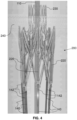
- the trampoline lattice 230 can be integral with the adjustable stent lattice 210 or fixedly connected thereto, for example, by crimping, banding, welding.
- a set of hollow disconnect lumens 140 surround lattice drive wires 150 and both are operatively connected to a non-illustrated delivery and deployment handle (also referred to as a controller because it need not be shaped as a handle).
- the exemplary embodiment of the disconnect lumens 140 are tubes that extend from the handle to the implant 200 and each surround a drive wire 150.
- Lattice disconnect tubes 142 are respectively disposed at the end of each hollow disconnect lumens 140.
- the disconnect lumens 140 and the drive wires 150 (and the sheath 130 if desired) to retract away from the adjustable stent lattice 210.
- the collapsed or contracted state of the wall-retaining petals 248 only remains while the disconnect lumens 140 and the drive wires 150 remain connected to the adjustable stent lattice 210.
- the petals 248 are allowed to move to their steady state or pre-set orientation, which is a position where the petals 248 extend in a plane that is substantially perpendicular to the axis of the guidewire lumen 110.
- the connection can be integral or can be formed, for example, by crimping, banding, and/or welding.
- Deformable cells of the outer trampoline portion 232 allow the outer trampoline portion 232 to expand and contract substantially.
- the cells are substantially marquis-shaped or tear-drop shaped, but they can take other closed curved or straight shapes.
- the valve trampoline lattice 230 has figure-eight-shaped structures that, when attached together at their sides, form five rows of cells that circumscribe the valve trampoline lattice.
- the outer trampoline portion 232 includes the first four rows of tear-drop and marquis-shaped cells.
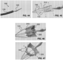
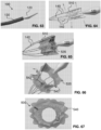
- FIGS. 44 to 47 illustrate an alternative embodiment of an actively controllable stent graft 300.
- This implant is similar in structure to the implant 200 except the wall-retaining petals 248 and the exterior implant skirt 240 are not present.
- the interior valve assembly also is not present, any valve assembly can be included within the adjustable stent lattice 310 of the implant 300.
- the implant 300 can be substantially circular or it can be D-shaped. As all other aspects of the implant 300 are similar to the implant 200, all features are not repeated to avoid unnecessary repetition. Likewise, where similar parts are referenced, the reference numeral is increased by 100.
- the tissue-fixation structures are extendible hooks 342 that are part of or attached to the adjustable stent lattice 310. Such hooks 342 can take the form of the needles 1700 or 2200 or 3070 shown and described in U.S. Patent Publication No. 2013/0046373 to Cartledge et al.
- One exemplary embodiment fixes a non-illustrated threaded nut within the distal jack strut 514 to allow the jack screw 520 to threadedly enter into and retract from a smooth-bored hollow in the distal jack strut 514 and places a rotationally free but longitudinally fixed connection of the jack screw 520 at the proximal jack strut 512.
- This relative movement of the intermediate strut 518 and the jack screw assemblies causes expansion of the adjustable stent lattice 510 when the proximal and distal jack struts 512, 514 move towards one another and causes contraction of the adjustable stent lattice 510 when the proximal and distal jack struts 512, 514 move away from one another.
- all of the jack screws 520 are rotated at the same speed to but such equal movement is not to be considered limiting.
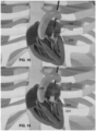
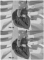
- FIGS. 82 to 87 A second alternative configuration of a circular valve replacement implant 600 is shown in FIGS. 82 to 87 .
- the implant 600 had an overall D-shape and the wall-retaining petals 648 were uncovered.
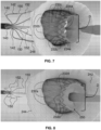
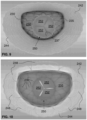
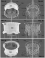
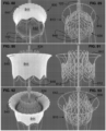
- the exemplary embodiment of the valve replacement implant 700 in FIGS. 82 to 87 likewise provides the trampoline lattice 730 with the inner circumferential valve portion 734 on the side opposite the implant skirt 740 projecting out from the side of the implant 700 with the wall-retaining petals 748 but is circular in its overall shape. Both the expandable outer trampoline portion 732 and the inner circumferential valve portion 734 are visible in FIG. 82 .
- the material 844 of the implant skirt 840 does not cover the wall-retaining petals 848, but it does project into the central orifices defined by each petal 848 in order to cover the proximal jack strut 812.
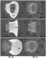
- the framework of the implant 800 is shown without the external coverings and valve material in FIGS. 89, 91, and 93 to expose the adjustable stent lattice 810, the skirt lattice 842, and the wall-retaining petals 848. Because the disconnect lumens 140 and the drive wires 150 connect from the side of the wall-retaining petals 848, the nosecone 120 is on the side of the implant skirt 840.
- FIGS. 94 and 95 A fourth alternative configuration of a circular valve replacement implant 900 is shown in FIGS. 94 and 95 .
- the implant 900 has no exterior skirt, has no wall-retaining petals, and does not have the trampoline valve.
- the implant 900 has an overall circular shape and a tricuspid valve with leaflets 952 attached to the interior of the adjustable stent lattice 910.
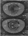
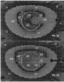
- FIGS. 96 to 99 A fifth alternative configuration of a circular valve replacement implant 1000 is shown in FIGS. 96 to 99 .
- the implant 1000 has a self-expanding valve trampoline lattice 1030 but it does not have an exterior skirt or wall-retaining petals.
- the trampoline lattice 1030 has an inner circumferential valve portion 1034 on a side where the disconnect lumens 140 project out from the proximal end of the adjustable stent lattice 1010.
- the expandable outer trampoline portion 1032 is visible from the interior of the implant 1000 in FIG. 96 and the inner circumferential valve portion 1034 is visible in both FIGS. 96 and 97 with the internal leaflets 1052 is visible in FIG. 97 .
- the framework of the implant 1000 is shown without the external coverings and valve material in FIGS. 98 and 99 to expose the adjustable stent lattice 1010 and the trampoline lattice 1030. Because the disconnect lumens 140 and the drive wires 150 connect from the side of the inner circumferential valve portion 1034, the nosecone 120 is on the side opposite the inner circumferential valve portion 1034.
- FIGS. 100 to 102 A sixth alternative configuration of a circular valve replacement implant 1100 is shown in FIGS. 100 to 102 .
- the implant 1100 has an exterior implant skirt 1140 but it does not have self-expanding valve trampoline lattice or wall-retaining petals.
- the valve contained within the adjustable stent lattice 1110 has three leaflets 1152, which are shown in FIGS. 100 and 101 .
- the implant 1100 is installed from the side of the adjustable stent lattice 1110 having the implant skirt 1140, the side where the disconnect lumens 140 project out from the proximal end of the adjustable stent lattice 1110. Because the disconnect lumens 140 and the drive wires 150 connect from the side of the implant skirt 1140, the nosecone 120 is on the side opposite the implant skirt 1140, as shown in FIG. 101 .
- This relative movement of the intermediate strut 1118 and the jack screw assemblies causes expansion of the adjustable stent lattice 1110 when the proximal and distal jack struts 1112, 1114 move towards one another and causes contraction of the adjustable stent lattice 1110 when the proximal and distal jack struts 1112, 1114 move away from one another.
- all of the jack screws 120 are rotated at the same speed to but such equal movement is not to be considered limiting.
- the adjustable stent lattice 1110 there are eight pairs of jack struts 1112, 1114 and eight intermediate struts 1118. This number is merely exemplary and there can be, for example, only six of each or any other number desired including any number from 1 to 10. Connecting the pairs of jack struts 1112, 1114 and the intermediate struts 1118 are the laterally extending arms 1116, which, in this exemplary embodiment is two for each of the proximal and distal jack struts 1112, 1114, but this number is not limiting.
- the arms 1116 each flex at their two endpoints, one at a respective intermediate strut 1118 and the other at a respective one of a pair of jack struts 1112, 1114.
- the arms 1116 move towards a longitudinal orientation (parallel to the jack screws and to the central axis of the lattice 1110.
- the arms 1116 angle away from the respective intermediate strut 1118 and one of the pair of jack struts 1112, 1114 in a circumferential orientation (perpendicular to the jack screws).
- the implant 1200 is installed from the skirt side of the adjustable stent lattice 1210 where the inner circumferential valve portion 1234 exists and the side where the disconnect lumens 140 project out from the proximal end of the adjustable stent lattice 1210. Because the disconnect lumens 140 and the drive wires 150 connect from the side of the inner circumferential valve portion 1234, the nosecone 120 is on the side opposite the inner circumferential valve portion 1234.
- the catheter sheaths required to implant these two are approximately 28 Fr to 32 Fr for the 25 mm to 40 mm size and 32 Fr to 35 Fr for the 40 mm to 55 mm size. Well within the desired range of catheters for such valve replacement procedures. It is further noted that if porcine pericardium is used for the valve leaflets, the size of the delivery sheath can be reduced, in particular, to 25 Fr to 29 Fr and 29 to 32 Fr, respectively.
Landscapes
- Health & Medical Sciences (AREA)
- Cardiology (AREA)
- Engineering & Computer Science (AREA)
- Biomedical Technology (AREA)
- Heart & Thoracic Surgery (AREA)
- Transplantation (AREA)
- Oral & Maxillofacial Surgery (AREA)
- Vascular Medicine (AREA)
- Life Sciences & Earth Sciences (AREA)
- Animal Behavior & Ethology (AREA)
- General Health & Medical Sciences (AREA)
- Public Health (AREA)
- Veterinary Medicine (AREA)
- Prostheses (AREA)
Claims (14)
- Mitralklappenimplantat (200, 300, 400, 500), aufweisend:ein kraftexpandierendes Mitralklappengitter (210) mit einer inneren Öffnung;ein selbstexpandierendes Herzklappen-Trampolingitter (230), das an der inneren Öffnung des kraftexpandierenden Mitralklappengitters (210) angebracht ist;dadurch gekennzeichnet, dass das kraftexpandierende Mitralklappengitter (210) eine Mehrzahl von Stellschrauben (220) umfasst, die zum Einstellen einer Konfiguration des Mitralklappengitters (210) ausgebildet sind, wobei das kraftexpandierende Mitralklappengitter (210) zu einer ersten Konfiguration selbstexpandierbar und von der ersten Konfiguration zu einer zweiten Konfiguration kraftexpandierbar ist.
- Implantat (200, 300, 400, 500) nach Anspruch 1, wobei das kraftexpandierende Mitralklappengitter (210) aus einem Formgedächtnismaterial gebildet ist, das auf eine bestimmte Form eingestellt ist.
- Implantat (200, 300, 400, 500) nach Anspruch 1, wobei die erste Konfiguration kreisförmig oder D-förmig ist und/oder wobei die zweite Konfiguration kreisförmig oder D-förmig ist.
- Implantat (200, 300, 400, 500) nach einem der vorstehenden Ansprüche, wobei das Herzklappen-Trampolingitter (230) einen zentralen Bereich hat, der Klappensegel (252) aufweist, wobei der zentrale Bereich vorzugsweise ein zylindrischer Abschnitt des Herzklappen-Trampolingitters (230) ist und die Klappensegel (252) innerhalb des zylindrischen Abschnitts aufgenommen sind.
- Implantat (200, 300, 400, 500) nach Anspruch 4, wobei das Herzklappen-Trampolingitter (230) einen D-förmigen Abschnitt aufweist, wobei die Klappensegel (252) vorzugsweise eine Einströmseite aufweisen und der D-förmige Abschnitt vorzugsweise auf einer Einströmseite der Klappensegel (252) angeordnet ist.
- Implantat (200, 300, 400, 500) nach einem der vorstehenden Ansprüche, wobei das Mitralklappengitter (210) eine Außenseite aufweist und ferner aufweisend eine sich nach außen erweiternde Implantatschürze (240), die an der Außenseite des Mitralklappengitters (210) angebracht und geformt ist, um an einer Seite einer nativen Mitralklappe (12) positioniert zu werden.
- Implantat (200, 300, 400, 500) nach einem der vorstehenden Ansprüche, ferner aufweisend Wandhaltedrähte (248), die an dem Mitralklappengitter (210) angebracht und geformt sind, um an einer Seite der nativen Mitralklappe (12) positioniert zu werden, wobei die Wandhaltedrähte (248) vorzugsweise die Form von Blütenblättern (248) und eine voreingestellte, radial nach außen gerichtete Gedächtnisform haben, um eine Kraft auf die Seite der nativen Mitralklappe (12) auszuüben, wenn das Mitralklappengitter (210) in einem Annulus der nativen Mitralklappe (12) expandiert wird.
- Implantat (200, 300, 400, 500) nach Anspruch 6 oder 7, wobei:die Implantatschürze (240) eine Implantatschürze für das linke Ventrikel oder das linke Atrium ist, die geformt ist, um auf der ventrikulären Seite beziehungsweise der atrialen Seite der nativen Mitralklappe (12) positioniert zu werden, wenn das Mitralklappengitter (210) innerhalb des Annulus der nativen Mitralklappe (12) expandiert wird; unddie Wandhaltedrähte (248) entsprechende linksatrium- oder linksventrikelseitige Wandhaltedrähte sind, die geformt sind, um auf einer atrialen Seite beziehungsweise ventrikulären Seite der nativen Mitralklappe (12) positioniert zu werden, wenn das Mitralklappengitter (210) innerhalb des Annulus der nativen Mitralklappe (12) expandiert wird.
- Implantat (200, 300, 400, 500) nach einem der vorstehenden Ansprüche, wobei:das Mitralklappengitter (210) ein Einlassende und ein Auslassende hat; undwobei das Herzklappen-Trampolingitter(230) am Einlassende oder Auslassende der inneren Öffnung angebracht ist.
- Mitralklappen-Implantatsystem, aufweisend das Implantat (200, 300, 400, 500) nach einem der vorstehenden Ansprüche und ein Zuführsystem (100), das zum aktiven Steuern der Expansion und Kontraktion des Implantats (200, 300, 400, 500) ausgebildet ist.
- System nach Anspruch 10, wobei das Zuführsystem (100) eine Mehrzahl von Implantatantriebsdrähten (150) aufweist und die Implantatantriebsdrähte (150) tempo-rär mit Stellschrauben (220) des Mitralklappengitters (210) verbindbar sind, so dass eine Rotation der Antriebsdrähte (150) in eine Richtung das Mitralklappengitter (210) kraftgetrieben expandiert und eine Rotation der Antriebsdrähte (150) in eine der einen Richtung entgegengesetzte Richtung das Mitralklappengitter (210) kraftgetrieben kontrahiert.
- Mitralklappen-Implantatsystem, aufweisend das Implantat (200, 300, 400, 500) nach einem der Ansprüche 1 bis 9 und ein Herzklappenzuführsystem (100), aufweisend:eine Steuerung;ein Führungsdrahtlumen (110), das mit der Steuerung verbunden ist und einen distalen Nasenkonus (120) hat;eine hohle externe Hülle (130), die das Führungsdrahtlumen (110) umgibt, ein mit der Steuerung verbundenes proximales Ende hat und dazu ausgebildet ist, aus einer ausgefahrenen, herzklappeninstallierten Position proximal zurückzuziehen;eine bestimmte Zahl von Implantatantriebsdrähten (150), die jeweils einen distalen Antriebsdrahtverbinder (152) haben; undhohle Verbindungslumen (140), in gleicher Anzahl zu der bestimmten Zahl und jeweils:auf einen entsprechenden der Antriebsdrähte (150) geschraubt;und mit einer distalen hohlen Verbindungshülse;wobei das selbstexpandierende und kraftexpandierende Mitralklappengitter (210) eine Zentralachse definiert und aufweist:proximale und distale Stellschraubenstrebenpaare (512, 514) in gleicher Anzahl zur bestimmten Zahl und parallel zur Zentralachse angeordnet;Zwischenstreben (518) in gleicher Anzahl zur bestimmten Zahl und parallel zur Zentralachse angeordnet, wobei jede Zwischenstrebe (518) zwischen zwei benachbarten der Stellschraubenstrebenpaare (512, 514) angeordnet ist;Arme (516), die jeweils benachbarte der Stellschraubenstrebenpaare (512, 514) und der Zwischenstreben (518) verbinden;die Mehrzahl von Stellschrauben (220):wobei jede drehbar mit einem Stellschraubenstrebenpaar (512, 514) verbunden ist;wobei diese zusammen mit den Stellschraubenstrebenpaaren (512, 514), den Zwischenstreben (518) und den Armen (216) das einstellbare Stentgitter (210, 510) bilden, wobei das einstellbare Stentgitter (210, 510) eine ventrikuläre Seite und eine atriale Seite aufweist;wobei diese dazu ausgebildet sind, das einstellbare Stentgitter (210, 510) reversibel kraftgetrieben zwischen einem komprimierten Zustand und einem vergrößerten Zustand zur Implantation des Mitralklappenrahmens in eine native Mitralklappe (12) zu expandieren und zu kontrahieren;und wobei diese jeweils einen Antriebsverbinder (152) haben, der geformt ist, um reversibel mit dem distalen Antriebsdrahtverbinder (152) eines der Antriebsdrähte (150) zu koppeln und zu verbinden und mit diesem verbunden zu bleiben, wenn die hohle Verbindungshülse (140) um den gekoppelten Antriebsverbinder (152) und distalen Antriebsdrahtverbinderangeordnet ist, so dass eine Rotation der Antriebsdrähte (150) entsprechend die Stellschrauben (220) rotiert, um das einstellbare Stentgitter (210, 510) kraftgetrieben zu expandieren oder zu kontrahieren;eine selbstexpandierende Implantatschürze (240), die an der ventrikulären Seite des einstellbaren Stentgitters (210, 510) angebracht ist, wobei die Implantatschürze (240) dazu ausgebildet ist, komprimiert und innerhalb der externen Hülle (130) gelagert zu werden, und sich selbst zu expandieren und dichtend an Gewebe an einer ventrikulären Seite der nativen Mitralklappe zu positionieren (12), wenn sie aus der externen Hülle (130) freigesetzt wird;Wandhaltedrähte (248), die an der atrialen Seite des einstellbaren Stentgitters (210, 510) befestigt und dazu ausgebildet sind, komprimiert und innerhalb der externen Hülle (130) gelagert zu werden, und sich selbst auf Gewebe an einer atrialen Seite der nativen Mitralklappe (12) zu expandieren, wenn sie an einer nativen Mitralklappe (12) aus der externen Hülle (130) freigesetzt werden;das selbstexpandierende Herzklappen-Trampolingitter (230), das im Inneren des einstellbaren Stentgitters (210, 510) angeordnet und damit verbunden ist, und aufweisend:
einen expandierbaren äußeren Trampolinabschnitt (232) mit einem umlaufenden Äußeren, das mit dem Inneren des einstellbaren Stentgitters (210, 510) verbunden ist, und einem umlaufenden Inneren; und einem inneren umlaufenden Ventilabschnitt (234):der mit dem umlaufenden Inneren verbunden ist und sich von dem umlaufenden Inneren nach innen erstreckt, um einen inneren zylindrischen Abschnitt zu definieren; undder ein kreisförmiges Ventil (250) mit inneren Klappensegeln (252) hat, die an dem inneren zylindrischen Abschnitt angeordnet sind. - System nach Anspruch 12, wobei:das einstellbare Stentgitter (210, 510) einen voreingestellten D-förmigen Querschnitt aufweist; unddas Äußere des expandierbaren äußeren Trampolinabschnitts (232) auf eine umlaufende D-Form voreingestellt ist, wobei die D-Form vorzugsweise im Wesentlichen eine D-Form eines nativen Mitralannulus (12) annähert.
- Mitralklappen-Implantatsystem, aufweisend:das Implantat (200, 300, 400, 500) nach einem der Ansprüche 1 bis 9,wobei das Mitralklappengitter (210) eine voreingestellte D-förmige Querschnittskonfiguration hat, die die innere Öffnung definiert, und eine Mehrzahl von Stellschrauben (220) umfasst, die dazu ausgebildet sind, das Mitralklappengitter (210) reversibel zwischen der ersten Konfiguration, die einer komprimierten Konfiguration entspricht, und der zweiten Konfiguration, die einer aufgeweiteten Konfiguration entspricht, kraftgetrieben zu expandieren und zu kontrahieren;eine sich nach außen erweiternde, selbstexpandierende Implantatschürze (240), die an einem Äußeren des Mitralklappengitters (210) angebracht ist, wobei die Implantatschürze (240) geformt ist, um an einer ventrikulären Seite einer nativen Mitralklappe (12) positioniert zu werden, um das Mitralklappengitter (210) im Annulus der nativen Mitralklappe (12) zu sichern;radial nach außen vorgespannte Wandhaltedrähte (248), die an dem Mitralklappengitter (210) angebracht und geformt sind, um an einer atrialen Seite der nativen Mitralklappe (12) positioniert zu werden, um das Mitralklappengitter (210) in dem Annulus der nativen Mitralklappe (12) zu sichern;das selbstexpandierende Herzklappen-Trampolingitter(230), das innere Klappensegel (252) enthält, wobei das Herzklappen-Trampolingitter (230) einen D-förmigen Abschnitt, der an dem Mitralklappengitter (210) angebracht ist, und einen im Wesentlichen zylindrischen inneren Abschnitt aufweist, wobei die Klappensegel (252) an dem im Wesentlichen zylindrischen inneren Abschnitt angebracht sind; undein Zuführsystem (100), das eine Mehrzahl von Implantatantriebsdrähten (150) aufweist, die temporär mit den Stellschrauben (220) verbindbar sind, so dass, wenn sie verbunden sind, eine Rotation der Antriebsdrähte (150) in eine Richtung das Mitralklappengitter (210) kraftgetrieben in Richtung der aufgeweiteten Konfiguration expandiert und eine Rotation der Antriebsdrähte (150) in einer der einen Richtung entgegengesetzten Richtung das Mitralklappengitter (210) kraftgetrieben in Richtung der komprimierten Konfiguration kontrahiert.
Applications Claiming Priority (3)
| Application Number | Priority Date | Filing Date | Title |
|---|---|---|---|
| US201562182820P | 2015-06-22 | 2015-06-22 | |
| US201562183451P | 2015-06-23 | 2015-06-23 | |
| PCT/US2016/038776 WO2016209970A1 (en) | 2015-06-22 | 2016-06-22 | Actively controllable heart valve implant and methods of controlling same |
Publications (3)
| Publication Number | Publication Date |
|---|---|
| EP3310302A1 EP3310302A1 (de) | 2018-04-25 |
| EP3310302A4 EP3310302A4 (de) | 2018-07-11 |
| EP3310302B1 true EP3310302B1 (de) | 2024-07-10 |
Family
ID=61656370
Family Applications (1)
| Application Number | Title | Priority Date | Filing Date |
|---|---|---|---|
| EP16815220.5A Active EP3310302B1 (de) | 2015-06-22 | 2016-06-22 | Aktiv steuerbares herzklappenimplantat |
Country Status (1)
| Country | Link |
|---|---|
| EP (1) | EP3310302B1 (de) |
Families Citing this family (20)
| Publication number | Priority date | Publication date | Assignee | Title |
|---|---|---|---|---|
| WO2019195860A2 (en) | 2018-04-04 | 2019-10-10 | Vdyne, Llc | Devices and methods for anchoring transcatheter heart valve |
| US10595994B1 (en) | 2018-09-20 | 2020-03-24 | Vdyne, Llc | Side-delivered transcatheter heart valve replacement |
| US11278437B2 (en) | 2018-12-08 | 2022-03-22 | Vdyne, Inc. | Compression capable annular frames for side delivery of transcatheter heart valve replacement |
| US11071627B2 (en) | 2018-10-18 | 2021-07-27 | Vdyne, Inc. | Orthogonally delivered transcatheter heart valve frame for valve in valve prosthesis |
| US12186187B2 (en) | 2018-09-20 | 2025-01-07 | Vdyne, Inc. | Transcatheter deliverable prosthetic heart valves and methods of delivery |
| US11344413B2 (en) | 2018-09-20 | 2022-05-31 | Vdyne, Inc. | Transcatheter deliverable prosthetic heart valves and methods of delivery |
| US10321995B1 (en) | 2018-09-20 | 2019-06-18 | Vdyne, Llc | Orthogonally delivered transcatheter heart valve replacement |
| US11109969B2 (en) | 2018-10-22 | 2021-09-07 | Vdyne, Inc. | Guidewire delivery of transcatheter heart valve |
| US11253359B2 (en) | 2018-12-20 | 2022-02-22 | Vdyne, Inc. | Proximal tab for side-delivered transcatheter heart valves and methods of delivery |
| WO2020146842A1 (en) | 2019-01-10 | 2020-07-16 | Vdyne, Llc | Anchor hook for side-delivery transcatheter heart valve prosthesis |
| US11185409B2 (en) | 2019-01-26 | 2021-11-30 | Vdyne, Inc. | Collapsible inner flow control component for side-delivered transcatheter heart valve prosthesis |
| US11273032B2 (en) | 2019-01-26 | 2022-03-15 | Vdyne, Inc. | Collapsible inner flow control component for side-deliverable transcatheter heart valve prosthesis |
| EP4729034A2 (de) | 2019-03-05 | 2026-04-22 | VDyne, Inc. | Trikuspidalregurgitationssteuerungsvorrichtungen für orthogonale transkatheterherzklappenprothese |
| US11076956B2 (en) | 2019-03-14 | 2021-08-03 | Vdyne, Inc. | Proximal, distal, and anterior anchoring tabs for side-delivered transcatheter mitral valve prosthesis |
| US11173027B2 (en) | 2019-03-14 | 2021-11-16 | Vdyne, Inc. | Side-deliverable transcatheter prosthetic valves and methods for delivering and anchoring the same |
| AU2020267390B2 (en) | 2019-05-04 | 2025-12-04 | Vdyne, Inc. | Cinch device and method for deployment of a side-delivered prosthetic heart valve in a native annulus |
| WO2021035032A1 (en) | 2019-08-20 | 2021-02-25 | Vdyne, Inc. | Delivery and retrieval devices and methods for side-deliverable transcatheter prosthetic valves |
| EP4684767A3 (de) | 2019-08-26 | 2026-04-08 | VDyne, Inc. | Seitlich freisetzbare transkatheter-prothesenventile |
| US11234813B2 (en) | 2020-01-17 | 2022-02-01 | Vdyne, Inc. | Ventricular stability elements for side-deliverable prosthetic heart valves and methods of delivery |
| EP4601585A1 (de) | 2022-10-14 | 2025-08-20 | Vdyne, Inc. | Vorrichtungen und verfahren zur freisetzung einer herzklappenprothese mit supraannularer stütze |
Family Cites Families (5)
| Publication number | Priority date | Publication date | Assignee | Title |
|---|---|---|---|---|
| US20080208327A1 (en) * | 2007-02-27 | 2008-08-28 | Rowe Stanton J | Method and apparatus for replacing a prosthetic valve |
| US9814611B2 (en) * | 2007-07-31 | 2017-11-14 | Edwards Lifesciences Cardiaq Llc | Actively controllable stent, stent graft, heart valve and method of controlling same |
| US20140358224A1 (en) * | 2013-05-30 | 2014-12-04 | Tendyne Holdlings, Inc. | Six cell inner stent device for prosthetic mitral valves |
| US9750607B2 (en) * | 2014-10-23 | 2017-09-05 | Caisson Interventional, LLC | Systems and methods for heart valve therapy |
| CA3005908A1 (en) * | 2015-12-03 | 2017-06-08 | Tendyne Holdings, Inc. | Frame features for prosthetic mitral valves |
-
2016
- 2016-06-22 EP EP16815220.5A patent/EP3310302B1/de active Active
Also Published As
| Publication number | Publication date |
|---|---|
| EP3310302A1 (de) | 2018-04-25 |
| EP3310302A4 (de) | 2018-07-11 |
Similar Documents
| Publication | Publication Date | Title |
|---|---|---|
| US11083576B2 (en) | Actively controllable heart valve implant and method of controlling same | |
| EP3310302A1 (de) | Aktiv steuerbares herzklappenimplantat und verfahren zur steuerung davon | |
| JP7507755B2 (ja) | 非円筒状のフレームを有する人工心臓弁 | |
| AU2019335206B2 (en) | Stent loading device | |
| JP6911012B2 (ja) | ドッキング要素及び人工弁要素を有する人工弁システム | |
| EP3399947B1 (de) | Klappenprothese mit strömungsrichter | |
| US9687341B2 (en) | Self-actuating sealing portions for paravalvular leak protection | |
| EP2699201B1 (de) | Transkatheterherzklappenprothesenfreisetzungssystem mit gesteuerter Expansion einer Herzklappenprothese | |
| US9999501B2 (en) | Valve prosthesis | |
| EP2575682B1 (de) | Transkatheterfreisetzungssystem für kontrollierte Expansion und Kontraktion einer Herzklappenprothese | |
| EP2911612B1 (de) | Klappenprothese | |
| US20260083553A1 (en) | Prosthetic heart valve having non-cylindrical frame | |
| EP4445872A2 (de) | Mechanisch expandierbare herzklappe mit segelklemmen | |
| EP4096581A1 (de) | System zur freisetzung einer herzklappenprothese. kugelschiebebefestigung | |
| CN108366856A (zh) | 具有作为用于自扩张假体的联接机构和展开机构的可收缩线材的递送系统 | |
| WO2008103283A2 (en) | Delivery systems and methods of implantation for replacement prosthetic heart valves | |
| JP2023525566A (ja) | 人工心臓弁リーフレット(弁尖)交連アセンブリおよび方法 | |
| US20230404750A1 (en) | Fabric Suture Valve Suspension System | |
| JP7655946B2 (ja) | 人工心臓弁の弁尖交連アセンブリ及び方法 | |
| EP4654925A1 (de) | Herzklappenprothese | |
| EP4378420B1 (de) | Stents für herzklappenprothesen |
Legal Events
| Date | Code | Title | Description |
|---|---|---|---|
| STAA | Information on the status of an ep patent application or granted ep patent |
Free format text: STATUS: THE INTERNATIONAL PUBLICATION HAS BEEN MADE |
|
| PUAI | Public reference made under article 153(3) epc to a published international application that has entered the european phase |
Free format text: ORIGINAL CODE: 0009012 |
|
| STAA | Information on the status of an ep patent application or granted ep patent |
Free format text: STATUS: REQUEST FOR EXAMINATION WAS MADE |
|
| 17P | Request for examination filed |
Effective date: 20180122 |
|
| AK | Designated contracting states |
Kind code of ref document: A1 Designated state(s): AL AT BE BG CH CY CZ DE DK EE ES FI FR GB GR HR HU IE IS IT LI LT LU LV MC MK MT NL NO PL PT RO RS SE SI SK SM TR |
|
| AX | Request for extension of the european patent |
Extension state: BA ME |
|
| RAP1 | Party data changed (applicant data changed or rights of an application transferred) |
Owner name: EDWARDS LIFESCIENCE CARDIAQ LLC |
|
| A4 | Supplementary search report drawn up and despatched |
Effective date: 20180607 |
|
| RIC1 | Information provided on ipc code assigned before grant |
Ipc: A61F 2/24 20060101AFI20180601BHEP |
|
| DAV | Request for validation of the european patent (deleted) | ||
| DAX | Request for extension of the european patent (deleted) | ||
| STAA | Information on the status of an ep patent application or granted ep patent |
Free format text: STATUS: EXAMINATION IS IN PROGRESS |
|
| 17Q | First examination report despatched |
Effective date: 20210913 |
|
| P01 | Opt-out of the competence of the unified patent court (upc) registered |
Effective date: 20230922 |
|
| GRAP | Despatch of communication of intention to grant a patent |
Free format text: ORIGINAL CODE: EPIDOSNIGR1 |
|
| STAA | Information on the status of an ep patent application or granted ep patent |
Free format text: STATUS: GRANT OF PATENT IS INTENDED |
|
| INTG | Intention to grant announced |
Effective date: 20240130 |
|
| GRAS | Grant fee paid |
Free format text: ORIGINAL CODE: EPIDOSNIGR3 |
|
| GRAA | (expected) grant |
Free format text: ORIGINAL CODE: 0009210 |
|
| STAA | Information on the status of an ep patent application or granted ep patent |
Free format text: STATUS: THE PATENT HAS BEEN GRANTED |
|
| AK | Designated contracting states |
Kind code of ref document: B1 Designated state(s): AL AT BE BG CH CY CZ DE DK EE ES FI FR GB GR HR HU IE IS IT LI LT LU LV MC MK MT NL NO PL PT RO RS SE SI SK SM TR |
|
| REG | Reference to a national code |
Ref country code: CH Ref legal event code: EP |
|
| REG | Reference to a national code |
Ref country code: DE Ref legal event code: R096 Ref document number: 602016088359 Country of ref document: DE |
|
| REG | Reference to a national code |
Ref country code: LT Ref legal event code: MG9D |
|
| REG | Reference to a national code |
Ref country code: NL Ref legal event code: MP Effective date: 20240710 |
|
| PG25 | Lapsed in a contracting state [announced via postgrant information from national office to epo] |
Ref country code: PT Free format text: LAPSE BECAUSE OF FAILURE TO SUBMIT A TRANSLATION OF THE DESCRIPTION OR TO PAY THE FEE WITHIN THE PRESCRIBED TIME-LIMIT Effective date: 20241111 |
|
| REG | Reference to a national code |
Ref country code: AT Ref legal event code: MK05 Ref document number: 1701378 Country of ref document: AT Kind code of ref document: T Effective date: 20240710 |
|
| PG25 | Lapsed in a contracting state [announced via postgrant information from national office to epo] |
Ref country code: NL Free format text: LAPSE BECAUSE OF FAILURE TO SUBMIT A TRANSLATION OF THE DESCRIPTION OR TO PAY THE FEE WITHIN THE PRESCRIBED TIME-LIMIT Effective date: 20240710 |
|
| PG25 | Lapsed in a contracting state [announced via postgrant information from national office to epo] |
Ref country code: PT Free format text: LAPSE BECAUSE OF FAILURE TO SUBMIT A TRANSLATION OF THE DESCRIPTION OR TO PAY THE FEE WITHIN THE PRESCRIBED TIME-LIMIT Effective date: 20241111 Ref country code: NL Free format text: LAPSE BECAUSE OF FAILURE TO SUBMIT A TRANSLATION OF THE DESCRIPTION OR TO PAY THE FEE WITHIN THE PRESCRIBED TIME-LIMIT Effective date: 20240710 |
|
| PG25 | Lapsed in a contracting state [announced via postgrant information from national office to epo] |
Ref country code: NO Free format text: LAPSE BECAUSE OF FAILURE TO SUBMIT A TRANSLATION OF THE DESCRIPTION OR TO PAY THE FEE WITHIN THE PRESCRIBED TIME-LIMIT Effective date: 20241010 |
|
| PG25 | Lapsed in a contracting state [announced via postgrant information from national office to epo] |
Ref country code: GR Free format text: LAPSE BECAUSE OF FAILURE TO SUBMIT A TRANSLATION OF THE DESCRIPTION OR TO PAY THE FEE WITHIN THE PRESCRIBED TIME-LIMIT Effective date: 20241011 Ref country code: PL Free format text: LAPSE BECAUSE OF FAILURE TO SUBMIT A TRANSLATION OF THE DESCRIPTION OR TO PAY THE FEE WITHIN THE PRESCRIBED TIME-LIMIT Effective date: 20240710 Ref country code: FI Free format text: LAPSE BECAUSE OF FAILURE TO SUBMIT A TRANSLATION OF THE DESCRIPTION OR TO PAY THE FEE WITHIN THE PRESCRIBED TIME-LIMIT Effective date: 20240710 |
|
| PG25 | Lapsed in a contracting state [announced via postgrant information from national office to epo] |
Ref country code: BG Free format text: LAPSE BECAUSE OF FAILURE TO SUBMIT A TRANSLATION OF THE DESCRIPTION OR TO PAY THE FEE WITHIN THE PRESCRIBED TIME-LIMIT Effective date: 20240710 |
|
| PG25 | Lapsed in a contracting state [announced via postgrant information from national office to epo] |
Ref country code: LV Free format text: LAPSE BECAUSE OF FAILURE TO SUBMIT A TRANSLATION OF THE DESCRIPTION OR TO PAY THE FEE WITHIN THE PRESCRIBED TIME-LIMIT Effective date: 20240710 |
|
| PG25 | Lapsed in a contracting state [announced via postgrant information from national office to epo] |
Ref country code: IS Free format text: LAPSE BECAUSE OF FAILURE TO SUBMIT A TRANSLATION OF THE DESCRIPTION OR TO PAY THE FEE WITHIN THE PRESCRIBED TIME-LIMIT Effective date: 20241110 Ref country code: AT Free format text: LAPSE BECAUSE OF FAILURE TO SUBMIT A TRANSLATION OF THE DESCRIPTION OR TO PAY THE FEE WITHIN THE PRESCRIBED TIME-LIMIT Effective date: 20240710 |
|
| PG25 | Lapsed in a contracting state [announced via postgrant information from national office to epo] |
Ref country code: HR Free format text: LAPSE BECAUSE OF FAILURE TO SUBMIT A TRANSLATION OF THE DESCRIPTION OR TO PAY THE FEE WITHIN THE PRESCRIBED TIME-LIMIT Effective date: 20240710 |
|
| PG25 | Lapsed in a contracting state [announced via postgrant information from national office to epo] |
Ref country code: ES Free format text: LAPSE BECAUSE OF FAILURE TO SUBMIT A TRANSLATION OF THE DESCRIPTION OR TO PAY THE FEE WITHIN THE PRESCRIBED TIME-LIMIT Effective date: 20240710 Ref country code: RS Free format text: LAPSE BECAUSE OF FAILURE TO SUBMIT A TRANSLATION OF THE DESCRIPTION OR TO PAY THE FEE WITHIN THE PRESCRIBED TIME-LIMIT Effective date: 20241010 |
|
| PG25 | Lapsed in a contracting state [announced via postgrant information from national office to epo] |
Ref country code: RS Free format text: LAPSE BECAUSE OF FAILURE TO SUBMIT A TRANSLATION OF THE DESCRIPTION OR TO PAY THE FEE WITHIN THE PRESCRIBED TIME-LIMIT Effective date: 20241010 Ref country code: PL Free format text: LAPSE BECAUSE OF FAILURE TO SUBMIT A TRANSLATION OF THE DESCRIPTION OR TO PAY THE FEE WITHIN THE PRESCRIBED TIME-LIMIT Effective date: 20240710 Ref country code: NO Free format text: LAPSE BECAUSE OF FAILURE TO SUBMIT A TRANSLATION OF THE DESCRIPTION OR TO PAY THE FEE WITHIN THE PRESCRIBED TIME-LIMIT Effective date: 20241010 Ref country code: LV Free format text: LAPSE BECAUSE OF FAILURE TO SUBMIT A TRANSLATION OF THE DESCRIPTION OR TO PAY THE FEE WITHIN THE PRESCRIBED TIME-LIMIT Effective date: 20240710 Ref country code: IS Free format text: LAPSE BECAUSE OF FAILURE TO SUBMIT A TRANSLATION OF THE DESCRIPTION OR TO PAY THE FEE WITHIN THE PRESCRIBED TIME-LIMIT Effective date: 20241110 Ref country code: HR Free format text: LAPSE BECAUSE OF FAILURE TO SUBMIT A TRANSLATION OF THE DESCRIPTION OR TO PAY THE FEE WITHIN THE PRESCRIBED TIME-LIMIT Effective date: 20240710 Ref country code: GR Free format text: LAPSE BECAUSE OF FAILURE TO SUBMIT A TRANSLATION OF THE DESCRIPTION OR TO PAY THE FEE WITHIN THE PRESCRIBED TIME-LIMIT Effective date: 20241011 Ref country code: FI Free format text: LAPSE BECAUSE OF FAILURE TO SUBMIT A TRANSLATION OF THE DESCRIPTION OR TO PAY THE FEE WITHIN THE PRESCRIBED TIME-LIMIT Effective date: 20240710 Ref country code: ES Free format text: LAPSE BECAUSE OF FAILURE TO SUBMIT A TRANSLATION OF THE DESCRIPTION OR TO PAY THE FEE WITHIN THE PRESCRIBED TIME-LIMIT Effective date: 20240710 Ref country code: BG Free format text: LAPSE BECAUSE OF FAILURE TO SUBMIT A TRANSLATION OF THE DESCRIPTION OR TO PAY THE FEE WITHIN THE PRESCRIBED TIME-LIMIT Effective date: 20240710 Ref country code: AT Free format text: LAPSE BECAUSE OF FAILURE TO SUBMIT A TRANSLATION OF THE DESCRIPTION OR TO PAY THE FEE WITHIN THE PRESCRIBED TIME-LIMIT Effective date: 20240710 |
|
| REG | Reference to a national code |
Ref country code: DE Ref legal event code: R097 Ref document number: 602016088359 Country of ref document: DE |
|
| PG25 | Lapsed in a contracting state [announced via postgrant information from national office to epo] |
Ref country code: DK Free format text: LAPSE BECAUSE OF FAILURE TO SUBMIT A TRANSLATION OF THE DESCRIPTION OR TO PAY THE FEE WITHIN THE PRESCRIBED TIME-LIMIT Effective date: 20240710 Ref country code: SM Free format text: LAPSE BECAUSE OF FAILURE TO SUBMIT A TRANSLATION OF THE DESCRIPTION OR TO PAY THE FEE WITHIN THE PRESCRIBED TIME-LIMIT Effective date: 20240710 Ref country code: RO Free format text: LAPSE BECAUSE OF FAILURE TO SUBMIT A TRANSLATION OF THE DESCRIPTION OR TO PAY THE FEE WITHIN THE PRESCRIBED TIME-LIMIT Effective date: 20240710 |
|
| PG25 | Lapsed in a contracting state [announced via postgrant information from national office to epo] |
Ref country code: EE Free format text: LAPSE BECAUSE OF FAILURE TO SUBMIT A TRANSLATION OF THE DESCRIPTION OR TO PAY THE FEE WITHIN THE PRESCRIBED TIME-LIMIT Effective date: 20240710 |
|
| PG25 | Lapsed in a contracting state [announced via postgrant information from national office to epo] |
Ref country code: CZ Free format text: LAPSE BECAUSE OF FAILURE TO SUBMIT A TRANSLATION OF THE DESCRIPTION OR TO PAY THE FEE WITHIN THE PRESCRIBED TIME-LIMIT Effective date: 20240710 |
|
| PG25 | Lapsed in a contracting state [announced via postgrant information from national office to epo] |
Ref country code: SK Free format text: LAPSE BECAUSE OF FAILURE TO SUBMIT A TRANSLATION OF THE DESCRIPTION OR TO PAY THE FEE WITHIN THE PRESCRIBED TIME-LIMIT Effective date: 20240710 Ref country code: IT Free format text: LAPSE BECAUSE OF FAILURE TO SUBMIT A TRANSLATION OF THE DESCRIPTION OR TO PAY THE FEE WITHIN THE PRESCRIBED TIME-LIMIT Effective date: 20240710 |
|
| PLBE | No opposition filed within time limit |
Free format text: ORIGINAL CODE: 0009261 |
|
| STAA | Information on the status of an ep patent application or granted ep patent |
Free format text: STATUS: NO OPPOSITION FILED WITHIN TIME LIMIT |
|
| 26N | No opposition filed |
Effective date: 20250411 |
|
| PGFP | Annual fee paid to national office [announced via postgrant information from national office to epo] |
Ref country code: DE Payment date: 20250402 Year of fee payment: 10 |
|
| PGFP | Annual fee paid to national office [announced via postgrant information from national office to epo] |
Ref country code: GB Payment date: 20250401 Year of fee payment: 10 |
|
| PGFP | Annual fee paid to national office [announced via postgrant information from national office to epo] |
Ref country code: FR Payment date: 20250508 Year of fee payment: 10 |
|
| PG25 | Lapsed in a contracting state [announced via postgrant information from national office to epo] |
Ref country code: SE Free format text: LAPSE BECAUSE OF FAILURE TO SUBMIT A TRANSLATION OF THE DESCRIPTION OR TO PAY THE FEE WITHIN THE PRESCRIBED TIME-LIMIT Effective date: 20240710 |
|
| REG | Reference to a national code |
Ref country code: CH Ref legal event code: H13 Free format text: ST27 STATUS EVENT CODE: U-0-0-H10-H13 (AS PROVIDED BY THE NATIONAL OFFICE) Effective date: 20260127 |
|
| PG25 | Lapsed in a contracting state [announced via postgrant information from national office to epo] |
Ref country code: MC Free format text: LAPSE BECAUSE OF FAILURE TO SUBMIT A TRANSLATION OF THE DESCRIPTION OR TO PAY THE FEE WITHIN THE PRESCRIBED TIME-LIMIT Effective date: 20240710 |
|
| PG25 | Lapsed in a contracting state [announced via postgrant information from national office to epo] |
Ref country code: LU Free format text: LAPSE BECAUSE OF NON-PAYMENT OF DUE FEES Effective date: 20250622 |
|
| REG | Reference to a national code |
Ref country code: BE Ref legal event code: MM Effective date: 20250630 |
|
| PG25 | Lapsed in a contracting state [announced via postgrant information from national office to epo] |
Ref country code: IE Free format text: LAPSE BECAUSE OF NON-PAYMENT OF DUE FEES Effective date: 20250622 |
|
| PG25 | Lapsed in a contracting state [announced via postgrant information from national office to epo] |
Ref country code: BE Free format text: LAPSE BECAUSE OF NON-PAYMENT OF DUE FEES Effective date: 20250630 |
|
| PG25 | Lapsed in a contracting state [announced via postgrant information from national office to epo] |
Ref country code: CH Free format text: LAPSE BECAUSE OF NON-PAYMENT OF DUE FEES Effective date: 20250630 |