EP3310409B1 - Okklusionsdetektionstechniken für eine fluidinfusionsvorrichtung mit einem drehpumpmechanismus - Google Patents
Okklusionsdetektionstechniken für eine fluidinfusionsvorrichtung mit einem drehpumpmechanismus Download PDFInfo
- Publication number
- EP3310409B1 EP3310409B1 EP16728196.3A EP16728196A EP3310409B1 EP 3310409 B1 EP3310409 B1 EP 3310409B1 EP 16728196 A EP16728196 A EP 16728196A EP 3310409 B1 EP3310409 B1 EP 3310409B1
- Authority
- EP
- European Patent Office
- Prior art keywords
- rotor
- fluid
- stator
- pump mechanism
- sensor
- Prior art date
- Legal status (The legal status is an assumption and is not a legal conclusion. Google has not performed a legal analysis and makes no representation as to the accuracy of the status listed.)
- Active
Links
Images


Classifications
-
- A—HUMAN NECESSITIES
- A61—MEDICAL OR VETERINARY SCIENCE; HYGIENE
- A61M—DEVICES FOR INTRODUCING MEDIA INTO, OR ONTO, THE BODY; DEVICES FOR TRANSDUCING BODY MEDIA OR FOR TAKING MEDIA FROM THE BODY; DEVICES FOR PRODUCING OR ENDING SLEEP OR STUPOR
- A61M5/00—Devices for bringing media into the body in a subcutaneous, intra-vascular or intramuscular way; Accessories therefor, e.g. filling or cleaning devices, arm-rests
- A61M5/14—Infusion devices, e.g. infusing by gravity; Blood infusion; Accessories therefor
- A61M5/142—Pressure infusion, e.g. using pumps
- A61M5/14212—Pumping with an aspiration and an expulsion action
- A61M5/14216—Reciprocating piston type
-
- A—HUMAN NECESSITIES
- A61—MEDICAL OR VETERINARY SCIENCE; HYGIENE
- A61M—DEVICES FOR INTRODUCING MEDIA INTO, OR ONTO, THE BODY; DEVICES FOR TRANSDUCING BODY MEDIA OR FOR TAKING MEDIA FROM THE BODY; DEVICES FOR PRODUCING OR ENDING SLEEP OR STUPOR
- A61M5/00—Devices for bringing media into the body in a subcutaneous, intra-vascular or intramuscular way; Accessories therefor, e.g. filling or cleaning devices, arm-rests
- A61M5/14—Infusion devices, e.g. infusing by gravity; Blood infusion; Accessories therefor
- A61M5/168—Means for controlling media flow to the body or for metering media to the body, e.g. drip meters, counters ; Monitoring media flow to the body
- A61M5/16831—Monitoring, detecting, signalling or eliminating infusion flow anomalies
- A61M2005/16863—Occlusion detection
Definitions
- Embodiments of the subject matter described herein relate generally to fluid infusion devices of the type suitable for delivering a medication fluid to the body of a patient. More particularly, embodiments of the subject matter presented herein relate to techniques for detecting an occlusion in the fluid delivery path of a fluid infusion device having a rotary pump mechanism.
- An exemplary medication fluid is insulin used in the management of diabetes.
- Certain diseases or conditions may be treated, according to modem medical techniques, by delivering a medication fluid or other substance to the body of a patient, either in a continuous manner or at particular times or time intervals within an overall time period.
- a medication fluid or other substance for example, diabetes is commonly treated by delivering defined amounts of insulin to the patient at appropriate times.
- Some common modes of providing insulin therapy to a patient include delivery of insulin through manually operated syringes and insulin pens.
- Other modern systems employ programmable fluid infusion devices (e.g., insulin pumps) to deliver controlled amounts of insulin to a patient.
- a fluid infusion device suitable for use as an insulin pump may be realized as an external device or an implantable device, which is surgically implanted into the body of the patient.
- External fluid infusion devices include devices designed for use in a generally stationary location (for example, in a hospital or clinic bedside environment), and devices configured for ambulatory or portable use (to be carried or worn by a patient).
- External fluid infusion devices may establish a fluid flow path from a fluid reservoir or cartridge to the patient via, for example, a suitable hollow tubing, needle, or other type of fluid conduit.
- a fluid infusion device can be implemented with a rotary micropump mechanism that accurately delivers a precise volume of fluid with each revolution or cycle.
- the inlet of the micropump is connected to a fluid source such as a reservoir, and the outlet of the micropump is connected to a fluid delivery conduit that leads to the body of the patient.
- the micropump draws fluid from the fluid source (via a vacuum or suction action) and then delivers a predictable volume of fluid with each cycle.
- a sensing element terminates at or near the stator cam surface.
- the sensing element cooperates with a detection circuit to detect whether or not the stator cam surface is in contact with the sensor contact element.
- the detection circuit monitors characteristics of a detection signal obtained from the sensing element in response to angular position of the rotor to determine an operating condition of the fluid pump mechanism.
- the fluid pump mechanism includes: a stator; a rotor; an inlet valve that opens and closes as a function of angular and axial position of the rotor; an outlet valve that opens and closes as a function of angular and axial position of the rotor; a sensor contact element; and a sensing element.
- the stator cam element has a stator cam surface, and the rotor includes a reference surface and a rotor cam element having a variable height rising from the reference surface. The rotor cam element cooperates with the stator cam element to axially displace the rotor, relative to the stator, as a function of angular position of the rotor.
- the sensor contact element resides on the reference surface in an area corresponding to a valve state in which the inlet valve is closed and the outlet valve is open.
- the sensing element terminates at or near the stator cam surface, and it cooperates with a detection circuit to detect whether or not the stator cam surface is in contact with the sensor contact element.
- the detection circuit monitors characteristics of a detection signal obtained from the sensing element in response to angular position of the rotor to determine an operating condition of the fluid pump mechanism.
- the fluid pump mechanism includes a stator with a stator cam element having a stator cam surface.
- the fluid pump mechanism also includes a rotor with a reference surface and a rotor cam element having a variable height rising from the reference surface.
- the rotor cam element cooperates with the stator cam element to axially displace the rotor, relative to the stator, as a function of angular position of the rotor.
- a biasing element provides a biasing force to urge the rotor cam element toward the stator cam element and toward the reference surface.
- a force sensor is coupled to the rotor. The force sensor generates output levels in response to force imparted thereto, and the force sensor cooperates with a detection circuit that obtains and processes the output levels to detect occlusions in a fluid path downstream of the fluid pump mechanism.
- a fluid pump mechanism includes a stator with a stator cam element having a stator cam surface, and a rotor with an optically detectable feature, a reference surface, and a rotor cam element having a variable height rising from the reference surface.
- the rotor cam element cooperates with the stator cam element to axially displace the rotor, relative to the stator, as a function of angular position of the rotor.
- the optically detectable feature rotates and axially translates as a function of angular position of the rotor.
- An optical detection circuit interrogates the optically detectable feature during operation of the fluid pump mechanism to determine an operating condition of the fluid pump mechanism.
- An exemplary embodiment of a fluid infusion device includes: a fluid pump mechanism; a biasing element; a subcutaneous conduit; a drive motor; and a detection circuit.
- the fluid pump mechanism cooperates with a fluid cartridge module, and the fluid pump mechanism includes a rotor and a stator.
- the rotor includes a reference surface and a rotor cam element having a variable height rising from the reference surface, and the stator includes a stator cam element having a stator cam surface.
- the rotor cam element cooperates with the stator cam element to axially displace the rotor, relative to the stator, as a function of angular position of the rotor.
- An exemplary embodiment of a fluid infusion device includes a fluid pump mechanism that cooperates with a fluid cartridge module.
- the fluid pump mechanism includes a rotor and a stator; the rotor has a reference surface and a rotor cam element having a variable height rising from the reference surface.
- the stator includes a stator cam element having a stator cam surface, wherein the rotor cam element cooperates with the stator cam element to axially displace the rotor, relative to the stator, as a function of angular position of the rotor.
- An exemplary embodiment of a fluid pump mechanism includes a stator with a stator cam element having a stator cam surface.
- the fluid pump mechanism also includes a rotor having: an endcap with a rim; a reference surface located inside the endcap; and a rotor cam element located inside the endcap and having a variable height rising from the reference surface.
- the rotor cam element cooperates with the stator cam element to axially displace the rotor, relative to the stator, as a function of angular position of the rotor.
- a first sensor contact element resides on the rim of the endcap, and is located at an angular position that follows an upper edge of the rotor cam element.
- the pump includes a stator, a rotationally drivable rotor disposed in the stator and axially movable between a retracted position and an extended position, a cam arrangement disposed between the rotor and the stator to apply a force to urge the rotor towards the extended position during a first part of the rotation of the rotor then remove the force on further rotation in each of repeated pump cycles, and a biasing element positioned to urge the rotor back towards the retracted position.
- the pump has a stator, a rotationally drivable rotor disposed in the stator and axially movable between a retracted position and an extended position, a cam arrangement disposed between the rotor and the stator to apply a force to urge the rotor towards the extended position during a first part of the rotation of the rotor then remove the force on further rotation in each of repeated pump cycles, and a biasing element positioned to urge the rotor back towards the retracted position.
- Also presented herein is an exemplary embodiment of a method of detecting occlusion in a pump for medication fluid of the type having a rotationally drivable rotor disposed in a stator and axially movable between a retracted position and an extended position, having a cam arrangement disposed between the rotor and the stator to apply a force in each of repeated pump cycles to urge the rotor towards the extended position during a first part of the rotation of the rotor then remove the force on further rotation, there being a biasing element positioned to urge the rotor back towards the retracted position, and having valving responsive to the angular position of the rotor including an inlet valve configured to open during a first arc of rotation for which the cam arrangement applies the force to the rotor and an outlet valve configured to open for a second arc of rotation after the force has been removed.
- Also presented herein is another embodiment of a method of detecting occlusion in a pump for medication fluid of the type having a rotationally drivable rotor disposed in a stator and axially movable between a retracted position and an extended position, having a cam arrangement disposed between the rotor and the stator to apply a force in each of repeated pump cycles to urge the rotor towards the extended position during a first part of the angular rotation of the rotor then remove the force on further rotation, there being a biasing element positioned to urge the rotor back towards the retracted position, and having valving responsive to the angular position of the rotor including an inlet valve configured to open during a first arc of rotation for which the cam arrangement applies the force to the rotor and an outlet valve configured to open for a second arc of rotation after the force has been removed.
- the following description relates to a fluid infusion device of the type used to treat a medical condition of a patient.
- the infusion device is used for infusing fluid (such as a medication) into the body of a user.
- fluid such as a medication
- the non-limiting examples described below relate to a medical device used to treat diabetes (more specifically, an insulin infusion device), although embodiments of the disclosed subject matter are not so limited.
- the infused medication fluid is insulin in certain embodiments.
- many other fluids may be administered through infusion such as, but not limited to, disease treatments, drugs to treat pulmonary hypertension, iron chelation drugs, pain medications, anti-cancer treatments, medications, vitamins, hormones, or the like.
- conventional features and characteristics related to infusion system operation, insulin pump operation, fluid reservoirs, and fluid conduits such as soft cannulas may not be described in detail here.
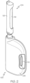
- the fluid infusion device 100 includes a housing 106 that serves as a shell for a variety of internal components.
- the housing 106 is suitably configured to receive, secure, and release the removable fluid cartridge module 104.
- the fluid cartridge module 104 can be received in a suitably shaped, sized, and configured cavity that is designed in accordance with certain physical characteristics of the fluid cartridge module 104.
- the housing 106 can include structural features that mate with or otherwise engage structural features of the fluid cartridge module 104.
- the illustrated embodiment of the removable fluid cartridge module 104 includes a retention mechanism 110 that secures the fluid cartridge module 104 in the properly installed and seated position within the fluid infusion device 100.
- the fluid infusion device 100 includes at least one user interface feature, which can be actuated by the patient as needed.
- the illustrated embodiment of the fluid infusion device 100 includes a button 112 that is physically actuated.
- the button 112 can be a multipurpose user interface if so desired to make it easier for the user to operate the fluid infusion device 100.
- the button 112 can be used in connection with one or more of the following functions, without limitation: waking up the processor and/or electronics of the fluid infusion device 100; triggering an insertion mechanism for actuating a transcutaneous conduit assembly (e.g., inserting a cannula into the subcutaneous space, or similar region of the patient); configuring one or more settings of the fluid infusion device 100; initiating delivery of medication fluid; initiating a fluid priming operation; disabling alerts or alarms generated by the fluid infusion device 100; and the like.
- the fluid infusion device 100 can employ a slider mechanism, a pin, a lever, or the like.
- the fluid infusion device 100 includes an adhesive element or adhesive material (hidden from view in FIG. 1 and FIG. 2 ) that can be used to affix the housing 106 to the body of the patient.
- the adhesive element can be located on the bottom surface of the housing 106 such that the housing 106 can be temporarily adhered to the skin of the patient.
- the adhesive element may be, for example, a piece of double sided adhesive tape that is cut into the desired shape and size.
- the fluid infusion device 100 is manufactured with an adhesive liner overlying the adhesive element; the adhesive liner is peeled away to expose the sticky surface of the adhesive element 114.
- the adhesive element is chosen to be strong enough to maintain the fluid infusion device 100 in place for the desired period of time (which is typically between one to seven days) and strong enough to withstand typical use cases (e.g., showering, rainy days, physical exercise, etc.), while also being easy to remove without discomfort.
- the fluid infusion device 100 is deployed in the following manner: (1) insert the fluid cartridge module 104 into the housing 106; (2) remove the adhesive liner; (3) affix the housing 106 to the body; and (4) insert the fluid delivery cannula into the body by pressing a button, pulling a tab, removing a safety pin, or otherwise activating an insertion mechanism to release a preloaded spring or equivalent actuation component. Thereafter, the fluid infusion device can be prepared for the delivery of the medication fluid as needed.
- the fluid cartridge module 104 is installed after the housing 106 is affixed to the body.
- the action of installing the fluid cartridge module 104 into the housing 106 engages or moves a mechanical, electrical, magnetic, or other type of interface, which in turn releases a preloaded spring or equivalent actuation component to insert the fluid delivery cannula into the body.
- the spring is released upon the first cartridge insertion, the fluid infusion device 100 is put into a different state such that subsequent installations of a fluid cartridge module will not trigger the insertion mechanism again.
- FIG. 3 depicts an embodiment of the fluid pump mechanism 136, which is fluidly coupled to the removable fluid cartridge module 104 during operation of the fluid infusion device 100.
- the fluid pump mechanism 136 can be realized as a rotationally actuated micro pump that delivers a calibrated amount of medication fluid with each delivery cycle.
- the fluid pump mechanism 136 includes a stator and a rotor; the rotor is actuated in a controlled manner by a drive motor 138.
- the fluid pump mechanism 136 functions by translating rotational movement of the rotor into axial displacement of the rotor relative to the stator.
- the illustrated embodiment of the system architecture 400 generally includes, without limitation: a printed circuit board 401; the removable fluid cartridge module 104; the fluid pump mechanism 136; the drive motor 138; a fluid flow path 402; a fluid flow path 404; a cartridge sensor 406; one or more status sensors 408; one or more alerting devices 410; an insertion mechanism 412; and a subcutaneous conduit 413.
- FIG. 4 includes a number of items that were previously described, and those items will not be redundantly described in detail here.
- the alerting devices 410 can be electrically coupled to the printed circuit board 401 for purposes of controlled activation. In this regard, activation of the alerting devices 410 can be controlled by the processor device 420 as needed. In certain embodiments, user manipulation of the button 112 results in actuation of the switch 423, which in turn disables alerts or alarms generated by the alerting devices 410.
- the dashed arrow labeled "Cartridge Trigger Option” in FIG. 4 represents mechanical interaction (and/or electrical, magnetic, inductive, optical, capacitive, or other detection methodology) between the fluid cartridge module 104 and the insertion mechanism 412.
- installation of the fluid cartridge module 104 into the housing 106 can be detected to trigger the insertion mechanism 412.
- the insertion mechanism 412 fires to position the subcutaneous conduit 413 into a subcutaneous location.
- a devoted insertion button 416 is used to fire the insertion mechanism 412. Accordingly, the dashed arrow labeled "Button Trigger Option" in FIG.
- various elements of the systems described herein are essentially the code segments or computer-readable instructions that perform the various tasks.
- the program or code segments are stored in a tangible processor-readable medium, which may include any medium that can store or transfer information.
- Examples of a non-transitory and processor-readable medium include an electronic circuit, a semiconductor memory device, a ROM, a flash memory, an erasable ROM (EROM), a floppy diskette, a CD-ROM, an optical disk, a hard disk, or the like.
- the software that performs the described functionality may reside and execute at, for example, an ASIC.
- the processor device 420 can implement, cooperate with, or otherwise support the operation of a detection circuit (and applicable processing logic) that functions to detect downstream occlusions in a fluid flow path, upstream occlusions in a fluid flow path, end of reservoir conditions in a fluid infusion device, and/or other detectable operating conditions.
- the processor device 420 can execute suitably written computer instructions that cause the processor device 420 to perform the various detection tasks, operations, and method steps described below in the context of the different detection methodologies.
- Patient-specific programming can be achieved through a physician programmer via a wired or wireless communication session.
- an infrared window can be provided in the housing of the fluid infusion device to accommodate wireless adjustments or programming.
- Other methods to adjust the basal rate utilize a dial, a knob, or other adjustment component that the physician or patient can manipulate.
- the adjustment component can be connected to the printed circuit board 401 and, specifically, to the processor device 420 for purposes of changing the timing and/or other characteristics of the fluid pump mechanism 136.
- FIG. 4 depicts a basal rate adjustment component 422 that is intended to represent the various methodologies and components that serve to adjust the programmed basal rate of the fluid infusion device 100.
- One simple and low cost way to visualize and confirm the adjustment involves the use of a clear window on the housing of the fluid infusion device and a colored dial with markings corresponding to the adjustment setting.
- the system architecture 400 may include or cooperate with any combination of alerting devices 410, including, without limitation: a vibration motor; a piezoelectric audio transducer; one or more indicator lights (e.g., light emitting diodes or other lamp components); a speaker protected by a hydrophobic membrane; and the like.
- alerting devices 410 including, without limitation: a vibration motor; a piezoelectric audio transducer; one or more indicator lights (e.g., light emitting diodes or other lamp components); a speaker protected by a hydrophobic membrane; and the like.
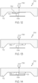
- the axial movement of the rotor 502 away from the stator 504 as shown in FIG. 6 is produced by a cam structure (not shown) acting between the rotor 502 and the stator 504 forcing them progressively apart during a portion of the rotation.
- the cam structure may comprise a rising land disposed on a transverse face of one of the rotor 502 and the stator 504 interacting with a projection or cam follower on the other.
- the cam structure could be a radial pin engaging a helical grove extending part way round one of the interacting cylindrical surfaces.
- the biasing element 506 (which may be realized as a spring, such as the spring coupler 164 shown in FIG. 3 ) provides a biasing force that urges the rotor 502 toward the stator 504.
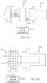
- the stator 704 has a different configuration than the stator 604 depicted in FIG. 9 , the operating concepts and functionality are identical for purposes of this description.
- the stator 704 includes a stator cam element 706 and a rotor opening 708 (as described above).
- the rotor 702 generally includes, without limitation: an endcap 712; a proximal axial extension 714; a distal axial extension 716; a first fluid supply channel 718 formed in the proximal axial extension 714; a second fluid supply channel 720 formed in the distal axial extension 716; and a rotor cam element 722.
- the fluid supply channels 718, 720 are realized as thin slits that extend from the outer surfaces of the axial extensions 714, 716. Sealing elements located inside the stator 704 cooperate with the fluid supply channels 718, 720 to act as valves that open and close as a function of the angular and axial position of the rotor 702 relative to the stator 704. This enables pumping of medication fluid supplied from the fluid cartridge module 104 (see FIG. 3 and FIG. 4 ) due to changes in volume available for fluid within the rotor chamber 610 caused by the axial displacement of the rotor 702.
- the endcap 712 can be suitably configured to mate with or otherwise cooperate with the drive motor 138, such that the angular position of the rotor 702 can be controlled as needed. Moreover, the endcap 712 can be suitably configured to mate with or otherwise cooperate with a biasing component that urges the rotor 702 toward the stator 704. For example, the endcap 712 can be coupled to or integrally fabricated with the spring coupler 164 shown in FIG. 3 .
- the axial displacement of the rotor 702 relative to the stator 704 is defined by the cooperating cam elements 706, 722.
- the cam elements contact each other during each pumping cycle to adjust the axial position of the rotor 702 as a function of the angular position of the rotor 702 relative to the stator 704.
- the rotor cam element 722 is positioned on the interior portion of the endcap 712, and it extends over a certain predefined arc.
- the rotor cam element 722 resembles a ramp having a variable height, i.e., progressively rising from a reference surface of the rotor 702. More specifically, the rotor cam element 722 increases in height over the predefined arc.
- FIG. 12 depicts a state where the stator cam element 706 resides on the rotor cam element 722. More specifically, the stator cam element 706 is positioned on the sloped portion of the rotor cam element 722. As the stator cam element 706 continues to "ride” along the rotor cam element 722, the rotor 702 becomes displaced relative to the stator 704. The maximum displacement occurs at the highest section (the plateau) of the rotor cam element 722. This maximum displacement in the discussion that follows is also referred to as the "extended” position.
- the illustrated embodiment of the rotor cam element 722 ends abruptly, as best shown in FIG. 13 , which depicts the vertical "shelf” defined at the end of the rotor cam element 722.
- FIG. 13 depicts the vertical "shelf” defined at the end of the rotor cam element 722.
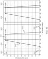
- FIG. 15 is a graph that includes a plot of rotor axial position versus rotor angular position, for normal and typical operating conditions.
- the vertical axis indicates the axial position (displacement) of the rotor 702 relative to the stator 704, and the horizontal axis indicates the angular position of the rotor 702.
- One pumping cycle corresponds to 360 degrees of rotation, and FIG. 15 depicts a plot that spans two pumping cycles.
- FIG. 15 includes regions superimposed over the plot; the regions represent periods during which the valves are open.
- the fourth section 820 of the plot corresponds to a period of time immediately after the stator cam element 706 travels beyond the rotor cam element 722 (see FIG. 13 and FIG. 14 ).
- the stator cam element 706 "falls off' and disengages the plateau of the rotor cam element 722, and the biasing force axially displaces the rotor 702 toward the stator 704 such that the rotor cam element 722 moves toward the reference surface 736.
- the stator cam element 706 reaches and contacts the reference surface 736 and the rotor has returned to its axially retracted position.
- the fourth section 820 of the plot corresponds to a fluid expulsion period.
- the fifth section 822 of the plot (where the axial displacement is approximately zero) corresponds to another period during which the stator cam element 706 is in contact with the reference surface 736.
- the stator cam element 706 is in contact with the reference surface 736.
- the fifth section 822 is akin to the first section 814, and the next pumping cycle proceeds as the rotor 702 continues to rotate.
- the occlusion detection methodology presented here utilizes a sensor system integrated into the fluid pump mechanism.
- the basic design, configuration, and operation of the fluid pump mechanism are consistent with that previously described.
- the sensor system includes a metal trace or similarly conductive sensor contact element that is installed on or integrated into the rotor and in the area away from the rotor cam element (also referred to as the "off-ramp position").
- the sensor system also includes a sensing element on or integrated into the stator, wherein the sensing element cooperates with the sensor contact element during operation of the fluid pump mechanism.
- the sensing element is realized as two discrete traces or conductive leads that terminate in the area of the stator cam element.
- the sensor contact element can be shaped, sized, and positioned such that the stator cam element only makes contact with the sensor contact element during normal fluid delivery operations (and such that the stator cam element does not make contact with the sensor contact element when the downstream fluid path is occluded). This can be done by placing the sensor contact at the appropriate angular position on the rotor so that it contacts the conductive leads on the stator cam element following a successful expulsion of fluid. If the expulsion cannot occur due to a downstream occlusion, the sensor contact on the rotor does not reach the conductive leads on the stator. This angular position depends on the discharge valve timing.
- the contact needs to be positioned to sense whether the rotor reaches the retracted position as a result of discharge through the outlet valve. In the cycle of rotation the earliest position for the contact would be while the discharge valve is still open, and in normal circumstances, the discharge will already have occurred. The latest position corresponds to time immediately before the opening of the inlet valve for the next pumping cycle.
- the conductive traces on the stator can be interconnected to appropriately configured electronics, a detection circuit, a processor, or the like.
- Software running on the fluid infusion device can monitor the state of the sensor system (open/close, high/low, etc.) to determine an operating condition, such as the state of fluid delivery.
- the detection circuit observes one binary pattern produced by the sensor system (open, close, open, close, etc.) that correlates to the various intake and expulsion cycles.
- the detection circuit observes a different binary pattern (e.g., open, open), which in turn initiates an alarm or an alert message.
- the leads 878, 880 cooperate with the detection circuit 856 to detect whether or not the stator cam surface 876 is in contact with the sensor contact element 870.
- the detection circuit 856 can monitor the characteristics of a detection signal that is obtained from the leads 878, 880 in response to the changing angular position of the rotor 852.
- the detection signal could be a measured voltage, current, or the like, having two measurable states corresponding to a contact state and a non-contact state.
- the sensor contact element 870 is shaped, sized, and positioned such that, under normal and expected operating conditions, the stator cam element 874 is in contact with the sensor contact element 870 immediately following each fluid expulsion period.
- the stator cam element 874 remains in contact with the sensor contact element 870 for a defined angular range of the rotor 852, but the sensor contact element 870 ends before the angular position that corresponds to the next fluid intake period (i.e., the sensor contact element 870 ends before the lower edge 866 of the rotor cam element 864.
- the sensor contact element 870 is located in an area on the reference surface 862 that corresponds to a valve state in which the inlet valve is closed and the outlet valve is open (see FIG. 15 and FIG. 16 ).
- at least a portion of the sensor contact element 870 can be located in an area on the reference surface 862 that corresponds to a valve state in which both the inlet valve and the outlet valve are closed.
- the sensor contact element is instead located on the rim 882 of the endcap 858 (see FIG. 17 ).
- the angular span of the sensor contact element can be identical or functionally equivalent to that shown in FIG. 17 for the sensor contact element 870. Locating the sensor contact element on the rim 882 instead of inside the endcap 858 may be desirable for ease of manufacturing, reliability, and robust performance.
- the electrically conductive leads of the stator 854 will also be relocated for compatibility with the alternative positioning of the sensor contact element.
- the leads can be located on a rim or other surface 884 of the stator 854. This type of arrangement is also shown in FIGS.
- the EAP sensor 906 is fabricated from a material (such as a thin film) that generates energy, electricity, voltage, current, or a measurable quantity as a function of mechanical stress or strain imparted thereto.
- the response of the EAP sensor 906 can be detected and analyzed by the detection circuit 908 as needed.
- the EAP sensor 906 is suitably configured to detect or measure the expansion and contraction of the fluid conduit 904 in an ongoing manner.
- the fluid conduit 904 will remain pressurized in the presence of a downstream occlusion until the inlet valve opens again for the next intake stroke. Opening of the inlet valve allows the pressurized fluid to backflow into the upstream fluid path, which in turn allows the resilient fluid conduit 904 to shrink or collapse (relative to its pressurized state).
- the detection circuit 908 can analyze the output of the EAP sensor 906, determine that a downstream occlusion has occurred, and take appropriate action such as generating an alert.
- the output of the EAP sensor 906 can also be monitored to detect an "end of reservoir" condition.
- the stopper of the fluid reservoir no longer moves because it has reached the limit of its travel.
- the fluid pump mechanism 902 generates a negative pressure on the inlet side, which collapses the fluid conduit 904 to a greater extent than experienced during normal delivery (and the fluid conduit 904 does not recover back to its nominal shape).
- FIG. 20 shows the EAP sensor 906 monitoring an upstream fluid conduit that resides between the fluid cartridge module 900 and the fluid pump mechanism 902.
- This arrangement can be effective at detecting upstream occlusions (e.g., an end of reservoir condition).
- the system can employ a similar EAP sensor to monitor expansion and contraction of a downstream fluid conduit that is located downstream of the fluid pump mechanism 902. Monitoring a downstream fluid conduit can be effective for purposes of detecting downstream occlusions.
- a rotary fluid pump mechanism includes a rotor and a stator that cooperate to draw fluid from a fluid reservoir and deliver the fluid to an outlet conduit.
- Axial displacement of the rotor relative to the stator is a function of the angular position of the rotor. Simply put, the rotor moves back and forth relative to the stator during normal and expected fluid pumping cycles.
- the occlusion detection methodology presented in this section employs at least one non-contact sensing scheme to monitor the position of the rotor relative to the stator during operation of the fluid pump mechanism.
- the axial position of the rotor 940 exhibits substantially different characteristics in the presence of a downstream occlusion, due to the back pressure caused by the occlusion (see FIG. 16 ).
- the techniques presented here detect the relative position of the rotor and/or the stator during operation of the fluid infusion device, and the detected position information is used to determine whether or not the downstream fluid path is occluded.
- the occlusion detection system includes a force or pressure sensor 954 that is suitably configured and arranged to measure the biasing force associated with the rotor 940.
- a biasing element can be employed to urge the rotor 940 toward the stator 942.
- the sensor 954 measures the force 956, which can vary during a fluid delivery cycle.
- the force 956 can be characterized for normal and expected fluid delivery cycles and for downstream occlusion conditions, and the detection circuit 946 can be designed and programmed in an appropriate manner to respond to changes in the detected force profile that might be indicative of a downstream occlusion.
- FIG. 23 is a simplified perspective view of an exemplary embodiment of a rotor 960 having an electrical contact 962 attached thereto
- FIG. 24 is a simplified diagram of an exemplary embodiment of an occlusion detection system that cooperates with the rotor 960.
- the occlusion detection system also includes a variable resistance element 964 that cooperates with the electrical contact 962 to form a potentiometer.
- the electrical contact 962 and the variable resistance element 964 can be electrically coupled to a detection circuit 966, which supports the occlusion detection methodology described here.
- the variable resistance element 964 can be realized as a component of the detection circuit 966.
- the variable resistance element 964 can be integrated with or coupled to the stator of the fluid pump mechanism if so desired.
- FIG. 24 depicts the rotor 960 at the sensor interrogation time, i.e., when the electrical contact 962 is touching the variable resistance element 964.
- the angular position of the rotor 960 corresponds to a desired interrogation or sampling point of the fluid delivery cycle.
- the electrical contact 962 can be placed such that it contacts the variable resistance element 964 immediately following each expected fluid expulsion period (see FIG. 15 ).
- the specific timing can be determined based on the known angular position characteristics of the fluid pump mechanism.
- the rotor 960 is axially displaced as a function of its angular position.
- the arrow 970 in FIG. 24 represents the axial displacement of the rotor 960.
- Axial displacement of the rotor 960 causes the electrical contact 962 to shift back and forth, because the electrical contact 962 is fixed relative to the rotor 960.
- the electrical contact 962 should make contact with the variable resistance element 964 within a predictable and repeatable range of possible locations. Consequently, the resistance of the potentiometer changes, and a measured quantity (e.g., voltage) as detected by the detection circuit 966 will be within a certain range during normal delivery cycles.
- the electrical contact 962 will touch the variable resistance element 964 at a considerably different location when the downstream fluid flow path is occluded. Accordingly, the resistance of the potentiometer and the measured voltage will be outside of the normal range of values when the output flow path is occluded.
- the detection circuit 966 can be designed and programmed in an appropriate manner to respond to changes in the resistance of the potentiometer that might be indicative of a downstream occlusion.
- FIG. 24 depicts an embodiment where the electrical contact 962 resides on the rotor 960 and the variable resistance element 964 is external to the rotor 960. In other embodiments, the variable resistance element 964 resides on the rotor 960 and the electrical contact 962 is external to the rotor 960. Regardless of which configuration is used, the operating principle remains the same.
- the conductive contact 996 is designed such that the resistance of the conductive contact 996 varies as a function of its physical compression and/or deflection.
- the conductive contact 996 compresses or deflects more as the gap between the rotor 994 and the conductive rim 992 closes. Conversely, the conductive element expands or returns to its nominal shape as the gap increases.
- the resistance of the conductive contact 996 changes as a function of the axial displacement of the rotor 994 relative to the stator 990.
- the resistance between the conductive contact 996 and the conductive rim 992 can be measured by the detection circuit, which can be suitably designed and programmed to respond to changes in the measured resistance that might be indicative of a downstream occlusion.
- the arrangement depicted in FIG. 26 and FIG. 27 can also be configured for use as a simple on/off switching mechanism.
- the detection circuit can be designed to detect whether or not the conductive contact 996 is electrically coupled to the conductive rim 992.
- the conductive contact 996 and the conductive rim 992 are configured such that an electrical connection is made only when the stator cam element resides on the reference surface.
- the detection circuit can detect the presence of a downstream occlusion in a manner similar to that described above with reference to FIGS. 17-19 .
- FIG. 28 is a simplified diagram of an exemplary embodiment of an occlusion detection system that utilizes one or more force sensors in cooperation with the fluid pump mechanism.
- FIG. 28 depicts a stator 1002, a rotor 1004, and a biasing element 1006 of a fluid pump mechanism that functions in the manner generally described above with reference to FIGS. 5-16 .
- FIG. 28 also shows a force sensor 1008 positioned between the rotor 1004 and the stator 1002, and another force sensor 1010 positioned such that it can measure the biasing force of the biasing element 1006.
- FIG. 29 is a simplified diagram of an exemplary embodiment of an occlusion detection system that utilizes optical sensing technology.
- FIG. 29 depicts a stator 1022 and a rotor 1024 of a fluid pump mechanism that functions in the manner generally described above with reference to FIGS. 5-16 .
- the rotor 1024 includes at least one optically detectable feature that can be monitored during the operation of the fluid pump mechanism.
- FIG. 28 also shows an exemplary embodiment of an optically detectable feature, which is realized as an optically detectable pattern 1026 located on an exposed surface 1028 of the rotor 1024.
- the optically detectable pattern 1026 is a dot array, which can be printed, affixed to, or integrated into the exposed surface 1028. Other types of optically detectable patterns 1026 can be employed if so desired.
- end of reservoir detection can employ one or more of the following general methodologies, without limitation: (1) detecting that the stopper has reached an end position; (2) detecting that the fluid pump mechanism is pulling on a vacuum rather than drawing in fluid; (3) measurement of the stopper position over the length of the reservoir; and (4) observing axial displacement characteristics of the rotor relative to the stator.
- the fluid infusion device includes an outlet conduit 1106 having an inlet end 1108 and an outlet end 1110.
- the inlet end 1108 is designed to penetrate a septum 1112 of the fluid reservoir 1104, and the outlet end 1110 is in fluid communication with the fluid pump mechanism.
- the inlet end 1108 enters the barrel of the fluid reservoir 1104 to establish fluid communication with the medication fluid inside the barrel.
- the fluid infusion device also includes an electrically conductive needle 1114.
- the needle 1114 has a contact end 1116 that is designed to penetrate the septum 1112 for entry into the barrel of the fluid reservoir 1104.
- the outlet conduit 1106 and the needle 1114 are electrically connected to a suitably configured detection circuit (not shown).
- the needle 1114 can be connected to a negative voltage terminal and the outlet conduit 1106 can be connected to a positive voltage terminal (or vice versa).
- the outlet conduit 1106 is shorted with the needle 1114.
- This action is akin to the closing of a switch (as described in the immediately preceding section), which can be monitored and detected by the detection circuit.
- the stopper 1102 will not create a short across the needle 1114 and the outlet conduit 1106.
- the detection circuit determines that the fluid reservoir 1104 is at the "end of reservoir” state.
- the detection circuit can take appropriate action when it detects this state. For example, the detection circuit can initiate an "end of reservoir" alert, an alarm, or a message intended for the user or a caregiver.
- the fluid infusion device that hosts the fluid reservoir 1120 includes a suitably configured detection circuit (not shown) that includes, controls, or otherwise cooperates with an excitation signal generator 1122 and an associated sensor 1124.
- the excitation signal generator 1122 can be coupled to the fluid reservoir 1120 for purposes of applying an excitation signal to the fluid reservoir 1120.
- the excitation signal can be, for example, a vibration signal having a particular frequency or a particular frequency spectrum that is suitable for measuring the resonance or other response of the fluid reservoir 1120.
- the resonance of the fluid reservoir 1120 is influenced by the volume and/or mass of the fluid remaining in the fluid reservoir 1120. In practice, the resonance of the fluid reservoir 1120 can be empirically determined or otherwise characterized for purposes of programming the detection circuit.
- the detection circuit can obtain and analyze the response signal in an appropriate manner to determine whether or not the fluid reservoir 1120 is empty. If the response signal is indicative of an empty reservoir, the detection circuit can take appropriate action, e.g., initiate an "end of reservoir” alert, an alarm, or a message intended for the user or a caregiver.
- FIG. 37 is a simplified diagram of an exemplary embodiment of an end of reservoir detection system for a fluid reservoir 1130 of a fluid infusion device.
- the fluid reservoir 1130 provides medication fluid to a fluid pump mechanism of the type described above. The manner in which the fluid pump mechanism functions and cooperates with the fluid reservoir 1130 will not be redundantly described in detail here.
- the fluid infusion device that hosts the fluid reservoir 1120 includes a suitably configured detection circuit 1132 that includes, controls, or otherwise cooperates with a force sensor 1134.
- the force sensor 1134 can be configured as described above with reference to FIG. 28 .
- the force sensor 1134 can be used to measure the force imparted by a biasing element 1136 (such as a spring) that is coupled to the stopper 1138 of the fluid reservoir 1130.
- the tension characteristics of the biasing element 1136 are selected such that the biasing element 1136 cannot independently move the stopper 1138.
- the force applied by the biasing element 1136 is too low to overcome the static friction of the stopper 1138, and the biasing element 1136 is not utilized to actuate the stopper 1138 or to otherwise deliver fluid from the fluid reservoir 1130.
- the stopper 1138 is designed to move only in response to the negative fluid pressure caused by the normal operation of the fluid pump mechanism, as described in detail above. Consequently, the biasing element 1136 is strictly utilized to provide a force measurement that corresponds to the position of the stopper 1138 within the fluid reservoir 1130.
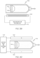
- FIG. 38 is a simplified diagram of an exemplary embodiment of an end of reservoir detection system for a fluid reservoir 1144 of a fluid infusion device.
- the fluid reservoir 1144 provides medication fluid to a fluid pump mechanism of the type described above. The manner in which the fluid pump mechanism functions and cooperates with the fluid reservoir 1144 will not be redundantly described in detail here.
- the fluid infusion device that hosts the fluid reservoir 1144 includes a suitably configured detection circuit 1146 that includes, controls, or otherwise cooperates with a pressure sensor 1148.
- the pressure sensor 1148 is designed to detect slight changes in the pressure of a sealed volume 1150 that is associated with the fluid reservoir 1144.
- FIG. 38 schematically depicts a vent 1152 leading from the sealed volume 1150 to the pressure sensor 1148. The vent 1152 allows the pressure sensor 1148 to monitor the pressure inside the sealed volume 1150 during operation of the fluid infusion device.
- the sealed volume 1150 can be defined by suitably configured structure of the fluid infusion device.
- the illustrated embodiment which is merely one possible implementation, includes a wall structure 1154 that at least partially surrounds the base of the fluid reservoir 1144.
- An airtight sealing element 1156 (such as an o-ring or a gasket) can be used to seal the wall structure 1154 against the outer surface of the fluid reservoir 1144.
- the sealed volume 1150 can be defined in any appropriate way, using additional structures or components if so desired.
- the shape and size of the sealed volume 1150 can vary from one embodiment to another.
- the pressure measurements obtained or otherwise processed by the detection circuit 1146 vary in accordance with the position of the stopper 1158 of the fluid reservoir 1144.
- the system is designed and configured such that the sealed volume 1150 does not adversely influence the normal operation of the fluid infusion device.
- the sealed volume 1150 should not impede the movement of the stopper 1158, which is caused by fluid intake strokes of the fluid pump mechanism.
- the detection circuit 1146 can obtain and analyze the output of the pressure sensor 1148 in an appropriate manner to determine whether or not the fluid reservoir 1144 is empty. If the measured pressure of the sealed volume 1150 is indicative of an empty reservoir, the detection circuit 1146 can take appropriate action, e.g., initiate an "end of reservoir" alert, an alarm, or a message intended for the user or a caregiver.
- the target 1166 and the coil element 1168 are suitably configured such that the inductance of the coil element 1168 varies (in a measurable manner) as a function of the position of the stopper 1164. Accordingly, the detection circuit 1170 observes a variable inductance as the stopper 1164 travels from the base of the fluid reservoir 1162 to the end position. The measured inductance can be correlated to the position of the stopper 1164, and the inductance corresponding to the end position of the stopper 1164 can be characterized for purposes of detecting the end of reservoir state. If the measured inductance of the coil element 1168 is indicative of an empty reservoir, the detection circuit 1170 can take appropriate action, e.g., initiate an "end of reservoir" alert, an alarm, or a message intended for the user or a caregiver.
- the system is provided with a device for detecting the presence of the stopper either at the forward position, thereby indicating that the barrel is empty or at intermediate positions giving an indication of the fill of the barrel.
- the outlet includes a needle passing through a septum in the outlet, the needle being positioned to be axially displaced by a contact with the stopper as it arrives at the forward position there being a switch operable by the needle outside of the barrel to indicate that the barrel is empty when the switch is actuated.
- the stopper and needle can be conductive closing an electrical circuit when the stopper touches the needle. In other arrangements, a second contact beside the needle is bridged by the presence of the stopper.
- Intermediate positions of the stopper can be detected by measuring the force in a spring extending from a position rearwardly of the stopper to a stopper, the pressure of a gas in the chamber behind the piston, the inductive properties of a ferromagnetic or conductive material within the stopper as detected by inductance from outside the reservoir or directed to detection of the liquid or stopper between the plates of a capacitor straddling the barrel.
- the detection of liquid in the barrel can be done by exciting the barrel rearwardly with respect to the stopper and detecting the excitation forward of the stopper. When the excitation and detection are either both adjacent, a non-liquid filled portion transmission between the excitation transducer and the reception transducer is improved due to the better impedance match.
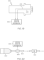
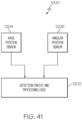
- FIG. 41 is a schematic block diagram of an exemplary embodiment of an end of reservoir detection system 1200 that can be implemented in a fluid infusion device having a rotary fluid pump mechanism.
- the fluid pump mechanism and the fluid reservoir are not shown in FIG. 41 .
- the manner in which the fluid pump mechanism functions and cooperates with the fluid reservoir will not be redundantly described in detail here.
- the angular position sensor 1206 is designed and configured to obtain angular position data of the rotor, where the angular position data indicates the rotational position of the rotor, relative to any convenient reference point.
- the angular position of the rotor can be expressed in degrees or in any appropriate units that correspond to angular measurement.
- the angular position sensor 1206 may be realized as a digital encoder or counter that monitors the operation of the drive motor, which in turn rotates the rotor.
- the respective sensor data or information is obtained by the detection circuit 1202 for processing and analysis. More specifically, the detection circuit 1202 can process the sensor data to determine whether or not an occlusion upstream of the fluid pump mechanism has occurred. The determination is based on certain detectable characteristics of the sensor data, wherein the detection circuit 1202 can determine whether the fluid pump mechanism is operating as expected to draw fluid in from the fluid reservoir and expel the fluid for delivery to the patient, or whether an upstream occlusion is preventing the fluid pump mechanism from drawing in fluid. As mentioned previously, an upstream occlusion may be detected when an inlet fluid flow path is blocked, or when the fluid reservoir is empty (and the stopper of the reservoir has reached its end position).
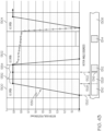
- the detection circuit 1202 calculates or otherwise obtains the axial velocity of the rotor during the fluid expulsion cycle.
- the section 820 of the plot represents the fluid expulsion period, during which the rotor normally "snaps back" into the stator under the force of the biasing element.
- the velocity of the rotor during this period can be characterized and predicted under normal and expected operating conditions. It should be understood that the slope of the section 820 is indicative of the axial velocity of the rotor (a gradual slope corresponds to lower velocity, and a steeper slope corresponds to higher velocity).
- an upstream occlusion is present (e.g., the fluid reservoir is empty and the stopper of the reservoir has reached its end position)
- the fluid pump mechanism will pull on a vacuum. Consequently, during the fluid intake period (corresponding to the section 816 of the plot in FIG. 15 ) the vacuum creates additional force in the same direction of the biasing force. This additional force increases the axial velocity of the rotor during the fluid expulsion cycle.
- the plot 1210 is characterized by a steeper slope during the expulsion period 1216.
- the steeper slope is indicative of higher axial velocity of the rotor during this time.
- the vacuum conditions created by an occlusion upstream of the fluid pump mechanism increase the axial velocity of the rotor during the fluid expulsion period (relative to the nominal axial velocity experienced during normal fluid delivery operations).
- the detection circuit 1202 is suitably configured and programmed to analyze the collected axial position and angular position sensor data in a way that is consistent with the comparison visualized in FIG. 42 .
- the detection circuit 1202 can calculate an average or maximum rotor axial velocity during the fluid expulsion period and compare the calculated velocity to a predetermined threshold axial velocity value. If the calculated axial velocity exceeds the threshold value, then the detection circuit 1202 can declare that an upstream occlusion has been detected.
- the detection circuit 1202 can consider the angular position data to determine the timing of the pumping cycle, such that the axial velocity of the rotor is analyzed during the fluid expulsion phase of the cycle (rather than at other times).
- the detection circuit 1202 can be programmed as needed to accurately characterize the axial velocity behavior of the rotor during the fluid expulsion period.
- the fluid expulsion period is characterized by a nominal axial velocity of the rotor
- the fluid expulsion period is characterized by a different axial velocity of the rotor, which is higher than the nominal axial velocity of the rotor.
- the upstream occlusion detection methodology presented in this section assumes that the fluid infusion device uses a fluid pump mechanism of the type described above, i.e., one having a stator and a cooperating rotor driven by a drive motor.
- the upstream occlusion detection methodology presented in this section analyzes the motor current of the drive motor to determine the operating condition or state of the fluid infusion device.
- one pumping cycle includes a fluid intake period (represented by the section 816 of the plot), a brief dwell period (represented by the section 818 of the plot), a fluid expulsion period (represented by the section 820 of the plot), and another dwell period (represented by the section 822 of the plot).
- the rotor cam element 722 travels along the stator cam element 706 during the fluid intake period and during the dwell period corresponding to the section 818 of the plot; the rotor cam element 722 disengages from the stator cam element 706 and moves toward the reference surface 736 during the fluid expulsion period; and the rotor cam element 722 travels along the reference surface 736 during the dwell period corresponding to the section 822 of the plot.
- the rotor cam element 722 travels along the stator cam element 706 during the fluid intake period and during the dwell period corresponding to the section 818 of the plot.
- the drive motor 138 is a DC motor, and that the current consumption of the drive motor 138 can be monitored and measured as it drives the rotor. It is well established that the current consumption of a DC motor is proportional to the output torque and the rotational speed (as torque increases, the current draw increases and the rotational speed decreases). Thus, when the rotor cam element 722 is traveling on the reference surface 736 and the applied biasing force is lower (the sections 814, 822 of the plot in FIG. 15 ), the motor current is somewhat stable, flat, and relatively low. In contrast, when the rotor cam element 722 is engaged with the stator cam element 706, the biasing spring force increases, which in turn increases the friction between the cam elements.
- the net effect is an increase in drive current consumption and torque output from the drive motor.
- the drive current peaks when the rotor cam element 722 reaches the plateau of the stator cam element 706, and then gradually decreases as the rotor cam element 722 continues traveling across the plateau. After the rotor cam element 722 disengages from the stator cam element 706 (i.e., the rotor cam element 722 falls off the plateau), the drive current returns to its relatively low and stable baseline level.
- the vacuum created by an empty reservoir or an upstream occlusion will increase the output torque during the fluid intake period (because the drive motor 138 must overcome the force created by the vacuum).
- the measured motor current will exhibit a steeper rise and a higher maximum value during the fluid intake period, relative to the normal motor current characteristics associated with non-occluded operation of the fluid pump mechanism.
- the detection circuit can be designed to take appropriate action if it observes this type of characteristic difference in the measured motor current. It should be appreciated that the methodology presented in this section can also be utilized to detect the presence of downstream occlusions if so desired.
- FIG. 43 also schematically depicts the reference surface 1306 of a rotor 1308; the reference surface 1306 is rendered in a straight line (rather than a circle as depicted in FIG. 44 ) aligned with the rotor angle axis of the graph.
- FIG. 44 does not depict the endcap or surrounding structure of the rotor 1308.
- the rotor 1308 includes a rotor cam element 1310 having a variable height that rises from the reference surface 1306, as described in detail above with reference to FIGS. 11-14 .
- the illustrated embodiment of the rotor 1308 also includes a first (leading) sensor contact element 1312 located on or integrated with the reference surface 1306, and a second (trailing) sensor contact element 1314 located on or integrated with the reference surface 1306. As will become apparent from the following description, the second sensor contact element 1314 is utilized to support downstream occlusion detection.
- the behavior of the fluid pump mechanism under normal and occluded conditions can be characterized such that the sensor contact elements 1312, 1314 can be sized and positioned in an appropriate manner.
- the sensing element on the stator cam element makes no contact with the first sensor contact element 1312 because the rotor remains axially displaced from the stator throughout the angular position that corresponds to the location of the first sensor contact element 1312 on the reference surface 1306.
- the sensing element contacts the second sensor contact element 1314 once per pumping cycle because the rotor resides at its baseline axial position throughout the angular position that corresponds to the location of the second sensor contact element 1314 on the reference surface 1306. Accordingly, under normal operating conditions, the detection circuit will detect contact with only the second sensor contact element 1314 for each pumping cycle.
- FIG. 44 the sensor contact elements 1312, 1314 are located on the reference surface 1306 of the rotor 1308. Moreover, the embodiment of FIG. 44 cooperates with a sensing element incorporated into the stator cam element (of the type described above with reference to FIGS. 18 and 19 ).
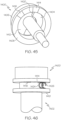
- FIG. 45 and FIG. 46 depict an alternative embodiment having a different arrangement of sensor contact elements.
- FIG. 45 is a perspective end view of an exemplary embodiment of a rotor 1400 of a fluid pump mechanism
- FIG. 46 is a side view that depicts the rotor 1400 cooperating with a compatible stator 1402 of the fluid pump mechanism.
- the first sensor contact element 1414 is located at an angular position that follows the upper edge 1420 of the rotor cam element 1404, and the second sensor contact element 1416 is located at an angular position that follows the first sensor contact element 1414.
- the plots shown in FIG. 43 for normal operating conditions, upstream occlusion conditions, and downstream occlusion conditions also apply to the embodiment depicted in FIG. 45 and FIG. 46 .
Landscapes
- Health & Medical Sciences (AREA)
- Vascular Medicine (AREA)
- Engineering & Computer Science (AREA)
- Anesthesiology (AREA)
- Biomedical Technology (AREA)
- Heart & Thoracic Surgery (AREA)
- Hematology (AREA)
- Life Sciences & Earth Sciences (AREA)
- Animal Behavior & Ethology (AREA)
- General Health & Medical Sciences (AREA)
- Public Health (AREA)
- Veterinary Medicine (AREA)
- Infusion, Injection, And Reservoir Apparatuses (AREA)
Claims (8)
- Rotationspumpe (500, 600) für ein Medikamentenfluid, umfassend:einen Stator (504, 604, 704);einen rotierbar antreibbaren Rotor (502, 602, 702), der in dem Stator (504, 604, 704) eingerichtet und zwischen einer eingefahrenen Position und einer erstreckten Position axial bewegbar ist, wobei der Rotor in der eingefahrenen Position vollständig innerhalb des Stators sitzt;eine Nockenanordnung (612, 706, 722), die zwischen dem Rotor (502, 602, 702) und dem Stator (504, 604, 704) eingerichtet ist, um eine Kraft auszuüben, um den Rotor (502, 602, 702) während eines ersten Teils der Rotation des Rotors (502, 602, 702) zu der erstreckten Position hin zu drängen und dann die Kraft bei einer weiteren Rotation in jedem der wiederholten Pumpenzyklen aufzuheben;ein Vorspannelement, das positioniert ist, um den Rotor (502, 602, 702) zurück in die eingefahrene Position zu drängen;Ventile, die auf die Winkelposition des Rotors (502, 602, 702) ansprechen, die ein Einlassventil (510), das konfiguriert ist, um sich während eines ersten Rotationsbogens zu öffnen, für den die Nockenanordnung (706, 722) die Kraft auf den Rotor (502, 602, 702) ausübt, und ein Auslassventil (512) einschließt, das konfiguriert ist, um sich für einen zweiten Rotationsbogen zu öffnen, nachdem die Kraft aufgehoben wurde; undeinen Verstopfungsdetektor;wobei der Verstopfungsdetektor einen elektrischen Kontakt (878, 880) auf einem von Rotor und dem Stator und eine leitende Kontaktfläche (870) auf dem anderen von dem Rotor und dem Stator aufweist;wobei der Kontakt (878, 880) und die leitende Kontaktfläche (870) axial und rotierbar positioniert sind, um nur dann einen Kontakt herzustellen, falls der Rotor die eingefahrene Position bis zu dem Ende des zweiten Rotationsbogens erreicht, wobei der Verstopfungsdetektor konfiguriert ist, um eine Verstopfung zu registrieren, falls ein solcher Kontakt nicht hergestellt wird.
- Pumpe nach Anspruch 1, wobei die leitende Kontaktfläche (870) positioniert ist, um über das Ende des zweiten Rotationsbogens hinaus, aber vor dem ersten Rotationsbogen des folgenden Zyklus der wiederholten Pumpenzyklen, Kontakt herstellt.
- Pumpe nach einem der vorstehenden Ansprüche, wobei der Rotor (502, 602, 702) eine Endkappe (609, 712) und eine axiale Erstreckung (508, 608) umfasst, die von der Endkappe (609, 712) vorsteht, wobei die axiale Erstreckung in einer Rotorkammer (610) in dem Stator (504, 604, 704) aufgenommen wird und die Endkappe (600, 712) sich radial über die Rotorkammer (610) hinaus erstreckt.
- Pumpe nach einem der vorstehenden Ansprüche, wobei die Nockenanordnung eine bogenförmige Rampe (722, 1404) umfasst, die einen Bereich von progressiv zunehmender Höhe aufweist, um die Kraft auszuüben, die den Rotor zu der erstreckten Position drängt, und auf einem von der Endkappe und dem Stator mit einem Nockenstößel (874) auf dem anderen von der Endkappe und des Stators koaxial eingerichtet ist.
- Pumpe nach Anspruch 4, wobei die bogenförmige Rampe (722, 1404) einen weiteren Bereich mit gleichmäßiger Höhe aufweist, der von dem Bereich mit progressiv zunehmender Höhe weiter verläuft, gefolgt von einem abrupten Ende.
- Pumpe nach einem der Ansprüche 4, wobei der elektrische Kontakt ein Paar von Kontakten auf dem Nockenstößel (874) umfasst und die leitende Kontaktfläche ein Streifen aus leitendem Material (870) ist, der koplanar mit einer Bezugsoberfläche auf der Höhe des Bodens der Rampe ist.
- Pumpe nach einem der Ansprüche 4, wobei die Endkappe (1406) eine herabhängende Schürze aufweist, die den Stator überspannt und in einem ringförmigen Rand (1408) endet;der Stator (1402) einen sich radial erstreckenden Flansch (1410) aufweist, der dem Rand (1408) der Schürze zugewandt ist; undwobei der elektrische Kontakt einen Verbinder (1426) auf einem von dem Rand (1408) und dem Flansch (1410) und einen Streifen aus leitendem Material (1414, 1416) auf dem anderen von dem Rand (1408) und dem Flansch (1410) umfasst.
- Pumpe nach einem der Ansprüche 4 bis 7, wobei die bogenförmige Rampe auf der Kappe koaxial mit der axialen Erstreckung eingerichtet ist und der Nockenstößel auf dem Stator eingerichtet ist.
Applications Claiming Priority (6)
| Application Number | Priority Date | Filing Date | Title |
|---|---|---|---|
| US14/746,641 US9879668B2 (en) | 2015-06-22 | 2015-06-22 | Occlusion detection techniques for a fluid infusion device having a rotary pump mechanism and an optical sensor |
| US14/746,648 US9993594B2 (en) | 2015-06-22 | 2015-06-22 | Occlusion detection techniques for a fluid infusion device having a rotary pump mechanism and rotor position sensors |
| US14/746,634 US10010668B2 (en) | 2015-06-22 | 2015-06-22 | Occlusion detection techniques for a fluid infusion device having a rotary pump mechanism and a force sensor |
| US14/746,654 US9878095B2 (en) | 2015-06-22 | 2015-06-22 | Occlusion detection techniques for a fluid infusion device having a rotary pump mechanism and multiple sensor contact elements |
| US14/746,624 US9987425B2 (en) | 2015-06-22 | 2015-06-22 | Occlusion detection techniques for a fluid infusion device having a rotary pump mechanism and sensor contact elements |
| PCT/US2016/034788 WO2016209554A1 (en) | 2015-06-22 | 2016-05-27 | Occlusion detection techniques for a fluid infusion device having a rotary pump mechanism |
Publications (2)
| Publication Number | Publication Date |
|---|---|
| EP3310409A1 EP3310409A1 (de) | 2018-04-25 |
| EP3310409B1 true EP3310409B1 (de) | 2024-07-03 |
Family
ID=56116583
Family Applications (1)
| Application Number | Title | Priority Date | Filing Date |
|---|---|---|---|
| EP16728196.3A Active EP3310409B1 (de) | 2015-06-22 | 2016-05-27 | Okklusionsdetektionstechniken für eine fluidinfusionsvorrichtung mit einem drehpumpmechanismus |
Country Status (5)
| Country | Link |
|---|---|
| EP (1) | EP3310409B1 (de) |
| JP (1) | JP6553216B2 (de) |
| CN (1) | CN107810021B (de) |
| CA (2) | CA3086724C (de) |
| WO (1) | WO2016209554A1 (de) |
Families Citing this family (25)
| Publication number | Priority date | Publication date | Assignee | Title |
|---|---|---|---|---|
| EP4732889A2 (de) | 2017-06-07 | 2026-04-29 | Supira Medical, Inc. | Vorrichtungen, systeme und verfahren zur bewegung intravaskulärer flüssigkeiten |
| US11511103B2 (en) | 2017-11-13 | 2022-11-29 | Shifamed Holdings, Llc | Intravascular fluid movement devices, systems, and methods of use |
| JP7410034B2 (ja) | 2018-02-01 | 2024-01-09 | シファメド・ホールディングス・エルエルシー | 血管内血液ポンプならびに使用および製造の方法 |
| WO2020028537A1 (en) | 2018-07-31 | 2020-02-06 | Shifamed Holdings, Llc | Intravascaular blood pumps and methods of use |
| WO2020073047A1 (en) | 2018-10-05 | 2020-04-09 | Shifamed Holdings, Llc | Intravascular blood pumps and methods of use |
| US12070578B2 (en) | 2019-04-19 | 2024-08-27 | Carefusion 303, Inc. | Medical tubing dimension scanning |
| WO2021011473A1 (en) | 2019-07-12 | 2021-01-21 | Shifamed Holdings, Llc | Intravascular blood pumps and methods of manufacture and use |
| US20220211941A1 (en) * | 2019-07-19 | 2022-07-07 | Medtrum Technologies Inc. | Integrated drug infusion device |
| US11654275B2 (en) | 2019-07-22 | 2023-05-23 | Shifamed Holdings, Llc | Intravascular blood pumps with struts and methods of use and manufacture |
| EP4010046A4 (de) | 2019-08-07 | 2023-08-30 | Calomeni, Michael | Katheterblutpumpen und zusammenklappbare pumpengehäuse |
| EP4034192B1 (de) | 2019-09-25 | 2025-12-24 | Supira Medical, Inc. | Intravaskuläre blutpumpensysteme und verfahren zur verwendung und steuerung davon |
| EP4034221B1 (de) | 2019-09-25 | 2024-11-13 | Shifamed Holdings, LLC | Katheterblutpumpen und zusammenklappbare pumpengehäuse |
| WO2021062260A1 (en) | 2019-09-25 | 2021-04-01 | Shifamed Holdings, Llc | Catheter blood pumps and collapsible blood conduits |
| WO2021101696A1 (en) * | 2019-11-21 | 2021-05-27 | Medtronic Minimed, Inc. | Systems for wearable infusion port and associated pump |
| EP4072650A4 (de) | 2019-12-11 | 2024-01-10 | Shifamed Holdings, LLC | Absteigende aorten- und hohlvenenblutpumpen |
| US12599758B2 (en) | 2019-12-19 | 2026-04-14 | Shifamed Holdings, Llc | Intravascular blood pumps, motors, and fluid control |
| US11602598B1 (en) | 2020-08-27 | 2023-03-14 | Fresenius Kabi Deutschland Gmbh | Prefilled syringe with pegfilgrastim having optimized dose and methods related thereto |
| KR102477255B1 (ko) * | 2020-09-10 | 2022-12-14 | 이오플로우(주) | 약물 주입 장치의 주입구 막힘 발생을 결정하는 방법, 장치 및 컴퓨터 프로그램 제품 |
| CN116669792A (zh) * | 2020-12-15 | 2023-08-29 | 贝克顿·迪金森公司 | 用于检测输液泵中的空储存器的装置和方法 |
| EP4059541A1 (de) * | 2021-03-15 | 2022-09-21 | Sensile Medical AG | Arzneimittelabgabevorrichtung |
| EP4059539A1 (de) * | 2021-03-15 | 2022-09-21 | Sensile Medical AG | Verfahren zur herstellung einer arzneimittelabgabevorrichtung |
| WO2022251642A1 (en) * | 2021-05-28 | 2022-12-01 | Insulet Corporation | Spring-based status sensors |
| CN116643617B (zh) * | 2023-06-01 | 2026-01-13 | 宁波方太厨具有限公司 | 旋钮、灶具及烟灶联动系统 |
| CN119714173B (zh) * | 2023-09-26 | 2025-09-30 | 大庆油田有限责任公司 | 一种单头螺杆泵定子内腔尺寸测量系统 |
| CN118391250B (zh) * | 2024-06-27 | 2024-08-23 | 佛山市顺德区凯硕精密模具自动化科技有限公司 | 一种压缩机泵体装配自动化在线检测设备 |
Citations (1)
| Publication number | Priority date | Publication date | Assignee | Title |
|---|---|---|---|---|
| US20130017099A1 (en) * | 2010-03-17 | 2013-01-17 | Sensile Pat Ag | Micropump |
Family Cites Families (10)
| Publication number | Priority date | Publication date | Assignee | Title |
|---|---|---|---|---|
| US4856339A (en) * | 1986-11-17 | 1989-08-15 | Centaur Sciences, Inc. | Medical infusion pump with sensors |
| CH679172A5 (de) * | 1989-10-06 | 1991-12-31 | Draegerwerk Ag | |
| DE4100886A1 (de) * | 1991-01-15 | 1992-07-16 | Zipperer M Cat Ingbuero | Kolbenbuerette |
| CH688224A5 (de) * | 1994-06-03 | 1997-06-30 | Saphirwerk Ind Prod | Implantierbare Vorrichtung fuer die dosierte Abgabe pharmazeutischer Flüssigkeiten im menschlichen oder tierischen Koerper. |
| EP1527793A1 (de) * | 2003-10-27 | 2005-05-04 | Ecole Polytechnique Fédérale de Lausanne (EPFL) | Mikropumpe zur Verabreichung von Arzneien |
| ATE409280T1 (de) * | 2005-12-28 | 2008-10-15 | Sensile Pat Ag | Mikropumpe |
| AU2011232741B2 (en) * | 2005-12-28 | 2012-12-20 | Sensile Medical Ag | Micropump |
| EP2275678B1 (de) * | 2009-07-13 | 2019-03-06 | Sensile Medical AG | Pumpe mit Rotorpositionsmessungssystem |
| JP5740950B2 (ja) * | 2010-12-09 | 2015-07-01 | セイコーエプソン株式会社 | 流体輸送装置、流体輸送方法 |
| JP6190807B2 (ja) * | 2011-08-17 | 2017-08-30 | フロー フォワード メディカル,インク. | 血液ポンプシステムと方法 |
-
2016
- 2016-05-27 JP JP2017566865A patent/JP6553216B2/ja active Active
- 2016-05-27 CA CA3086724A patent/CA3086724C/en active Active
- 2016-05-27 CN CN201680037039.8A patent/CN107810021B/zh active Active
- 2016-05-27 WO PCT/US2016/034788 patent/WO2016209554A1/en not_active Ceased
- 2016-05-27 EP EP16728196.3A patent/EP3310409B1/de active Active
- 2016-05-27 CA CA2985213A patent/CA2985213C/en active Active
Patent Citations (1)
| Publication number | Priority date | Publication date | Assignee | Title |
|---|---|---|---|---|
| US20130017099A1 (en) * | 2010-03-17 | 2013-01-17 | Sensile Pat Ag | Micropump |
Also Published As
| Publication number | Publication date |
|---|---|
| CA3086724A1 (en) | 2016-12-29 |
| CN107810021A (zh) | 2018-03-16 |
| CA2985213A1 (en) | 2016-12-29 |
| JP2018518320A (ja) | 2018-07-12 |
| WO2016209554A1 (en) | 2016-12-29 |
| EP3310409A1 (de) | 2018-04-25 |
| CN107810021B (zh) | 2023-06-30 |
| CA2985213C (en) | 2020-09-15 |
| JP6553216B2 (ja) | 2019-07-31 |
| CA3086724C (en) | 2022-08-02 |
Similar Documents
| Publication | Publication Date | Title |
|---|---|---|
| EP3310409B1 (de) | Okklusionsdetektionstechniken für eine fluidinfusionsvorrichtung mit einem drehpumpmechanismus | |
| US9993594B2 (en) | Occlusion detection techniques for a fluid infusion device having a rotary pump mechanism and rotor position sensors | |
| US9879668B2 (en) | Occlusion detection techniques for a fluid infusion device having a rotary pump mechanism and an optical sensor | |
| US9987425B2 (en) | Occlusion detection techniques for a fluid infusion device having a rotary pump mechanism and sensor contact elements | |
| US9878095B2 (en) | Occlusion detection techniques for a fluid infusion device having a rotary pump mechanism and multiple sensor contact elements | |
| US10010668B2 (en) | Occlusion detection techniques for a fluid infusion device having a rotary pump mechanism and a force sensor | |
| US20210038807A1 (en) | Fluid infusion patch pump device with automatic startup feature | |
| CN101175516B (zh) | 适于检测经皮装置脱离的医疗装置 | |
| EP4069333B1 (de) | Rotierende mikrofluidische medizinische pumpe | |
| US9416775B2 (en) | Internal cam metering pump | |
| JP2007530860A (ja) | 検出手段を備えるアクチュエータシステム | |
| US20240082486A1 (en) | Drug delivery device | |
| US12121699B1 (en) | Systems and methods for monitoring operations of an infusion delivery device using a pressure sensor |
Legal Events
| Date | Code | Title | Description |
|---|---|---|---|
| STAA | Information on the status of an ep patent application or granted ep patent |
Free format text: STATUS: THE INTERNATIONAL PUBLICATION HAS BEEN MADE |
|
| PUAI | Public reference made under article 153(3) epc to a published international application that has entered the european phase |
Free format text: ORIGINAL CODE: 0009012 |
|
| STAA | Information on the status of an ep patent application or granted ep patent |
Free format text: STATUS: REQUEST FOR EXAMINATION WAS MADE |
|
| 17P | Request for examination filed |
Effective date: 20180108 |
|
| AK | Designated contracting states |
Kind code of ref document: A1 Designated state(s): AL AT BE BG CH CY CZ DE DK EE ES FI FR GB GR HR HU IE IS IT LI LT LU LV MC MK MT NL NO PL PT RO RS SE SI SK SM TR |
|
| AX | Request for extension of the european patent |
Extension state: BA ME |
|
| DAV | Request for validation of the european patent (deleted) | ||
| DAX | Request for extension of the european patent (deleted) | ||
| PUAG | Search results despatched under rule 164(2) epc together with communication from examining division |
Free format text: ORIGINAL CODE: 0009017 |
|
| STAA | Information on the status of an ep patent application or granted ep patent |
Free format text: STATUS: EXAMINATION IS IN PROGRESS |
|
| 17Q | First examination report despatched |
Effective date: 20210121 |
|
| B565 | Issuance of search results under rule 164(2) epc |
Effective date: 20210121 |
|
| RIC1 | Information provided on ipc code assigned before grant |
Ipc: A61M 5/168 20060101ALI20210118BHEP Ipc: A61M 5/142 20060101AFI20210118BHEP |
|
| GRAP | Despatch of communication of intention to grant a patent |
Free format text: ORIGINAL CODE: EPIDOSNIGR1 |
|
| STAA | Information on the status of an ep patent application or granted ep patent |
Free format text: STATUS: GRANT OF PATENT IS INTENDED |
|
| INTG | Intention to grant announced |
Effective date: 20240229 |
|
| GRAS | Grant fee paid |
Free format text: ORIGINAL CODE: EPIDOSNIGR3 |
|
| GRAA | (expected) grant |
Free format text: ORIGINAL CODE: 0009210 |
|
| STAA | Information on the status of an ep patent application or granted ep patent |
Free format text: STATUS: THE PATENT HAS BEEN GRANTED |
|
| AK | Designated contracting states |
Kind code of ref document: B1 Designated state(s): AL AT BE BG CH CY CZ DE DK EE ES FI FR GB GR HR HU IE IS IT LI LT LU LV MC MK MT NL NO PL PT RO RS SE SI SK SM TR |
|
| REG | Reference to a national code |
Ref country code: CH Ref legal event code: EP |
|
| REG | Reference to a national code |
Ref country code: DE Ref legal event code: R096 Ref document number: 602016088214 Country of ref document: DE |
|
| REG | Reference to a national code |
Ref country code: LT Ref legal event code: MG9D |
|
| REG | Reference to a national code |
Ref country code: NL Ref legal event code: MP Effective date: 20240703 |
|
| PG25 | Lapsed in a contracting state [announced via postgrant information from national office to epo] |
Ref country code: PT Free format text: LAPSE BECAUSE OF FAILURE TO SUBMIT A TRANSLATION OF THE DESCRIPTION OR TO PAY THE FEE WITHIN THE PRESCRIBED TIME-LIMIT Effective date: 20241104 |
|
| REG | Reference to a national code |
Ref country code: AT Ref legal event code: MK05 Ref document number: 1699150 Country of ref document: AT Kind code of ref document: T Effective date: 20240703 |
|
| PG25 | Lapsed in a contracting state [announced via postgrant information from national office to epo] |
Ref country code: NL Free format text: LAPSE BECAUSE OF FAILURE TO SUBMIT A TRANSLATION OF THE DESCRIPTION OR TO PAY THE FEE WITHIN THE PRESCRIBED TIME-LIMIT Effective date: 20240703 |
|
| PG25 | Lapsed in a contracting state [announced via postgrant information from national office to epo] |
Ref country code: PT Free format text: LAPSE BECAUSE OF FAILURE TO SUBMIT A TRANSLATION OF THE DESCRIPTION OR TO PAY THE FEE WITHIN THE PRESCRIBED TIME-LIMIT Effective date: 20241104 Ref country code: NL Free format text: LAPSE BECAUSE OF FAILURE TO SUBMIT A TRANSLATION OF THE DESCRIPTION OR TO PAY THE FEE WITHIN THE PRESCRIBED TIME-LIMIT Effective date: 20240703 |
|
| PG25 | Lapsed in a contracting state [announced via postgrant information from national office to epo] |
Ref country code: NO Free format text: LAPSE BECAUSE OF FAILURE TO SUBMIT A TRANSLATION OF THE DESCRIPTION OR TO PAY THE FEE WITHIN THE PRESCRIBED TIME-LIMIT Effective date: 20241003 |
|
| PG25 | Lapsed in a contracting state [announced via postgrant information from national office to epo] |
Ref country code: PL Free format text: LAPSE BECAUSE OF FAILURE TO SUBMIT A TRANSLATION OF THE DESCRIPTION OR TO PAY THE FEE WITHIN THE PRESCRIBED TIME-LIMIT Effective date: 20240703 Ref country code: FI Free format text: LAPSE BECAUSE OF FAILURE TO SUBMIT A TRANSLATION OF THE DESCRIPTION OR TO PAY THE FEE WITHIN THE PRESCRIBED TIME-LIMIT Effective date: 20240703 Ref country code: GR Free format text: LAPSE BECAUSE OF FAILURE TO SUBMIT A TRANSLATION OF THE DESCRIPTION OR TO PAY THE FEE WITHIN THE PRESCRIBED TIME-LIMIT Effective date: 20241004 |
|
| PG25 | Lapsed in a contracting state [announced via postgrant information from national office to epo] |
Ref country code: BG Free format text: LAPSE BECAUSE OF FAILURE TO SUBMIT A TRANSLATION OF THE DESCRIPTION OR TO PAY THE FEE WITHIN THE PRESCRIBED TIME-LIMIT Effective date: 20240703 |
|
| PG25 | Lapsed in a contracting state [announced via postgrant information from national office to epo] |
Ref country code: LV Free format text: LAPSE BECAUSE OF FAILURE TO SUBMIT A TRANSLATION OF THE DESCRIPTION OR TO PAY THE FEE WITHIN THE PRESCRIBED TIME-LIMIT Effective date: 20240703 |
|
| PG25 | Lapsed in a contracting state [announced via postgrant information from national office to epo] |
Ref country code: IS Free format text: LAPSE BECAUSE OF FAILURE TO SUBMIT A TRANSLATION OF THE DESCRIPTION OR TO PAY THE FEE WITHIN THE PRESCRIBED TIME-LIMIT Effective date: 20241103 Ref country code: AT Free format text: LAPSE BECAUSE OF FAILURE TO SUBMIT A TRANSLATION OF THE DESCRIPTION OR TO PAY THE FEE WITHIN THE PRESCRIBED TIME-LIMIT Effective date: 20240703 |
|
| PG25 | Lapsed in a contracting state [announced via postgrant information from national office to epo] |
Ref country code: HR Free format text: LAPSE BECAUSE OF FAILURE TO SUBMIT A TRANSLATION OF THE DESCRIPTION OR TO PAY THE FEE WITHIN THE PRESCRIBED TIME-LIMIT Effective date: 20240703 Ref country code: CZ Free format text: LAPSE BECAUSE OF FAILURE TO SUBMIT A TRANSLATION OF THE DESCRIPTION OR TO PAY THE FEE WITHIN THE PRESCRIBED TIME-LIMIT Effective date: 20240703 |
|
| PG25 | Lapsed in a contracting state [announced via postgrant information from national office to epo] |
Ref country code: ES Free format text: LAPSE BECAUSE OF FAILURE TO SUBMIT A TRANSLATION OF THE DESCRIPTION OR TO PAY THE FEE WITHIN THE PRESCRIBED TIME-LIMIT Effective date: 20240703 Ref country code: RS Free format text: LAPSE BECAUSE OF FAILURE TO SUBMIT A TRANSLATION OF THE DESCRIPTION OR TO PAY THE FEE WITHIN THE PRESCRIBED TIME-LIMIT Effective date: 20241003 |
|
| PG25 | Lapsed in a contracting state [announced via postgrant information from national office to epo] |
Ref country code: RS Free format text: LAPSE BECAUSE OF FAILURE TO SUBMIT A TRANSLATION OF THE DESCRIPTION OR TO PAY THE FEE WITHIN THE PRESCRIBED TIME-LIMIT Effective date: 20241003 Ref country code: PL Free format text: LAPSE BECAUSE OF FAILURE TO SUBMIT A TRANSLATION OF THE DESCRIPTION OR TO PAY THE FEE WITHIN THE PRESCRIBED TIME-LIMIT Effective date: 20240703 Ref country code: NO Free format text: LAPSE BECAUSE OF FAILURE TO SUBMIT A TRANSLATION OF THE DESCRIPTION OR TO PAY THE FEE WITHIN THE PRESCRIBED TIME-LIMIT Effective date: 20241003 Ref country code: LV Free format text: LAPSE BECAUSE OF FAILURE TO SUBMIT A TRANSLATION OF THE DESCRIPTION OR TO PAY THE FEE WITHIN THE PRESCRIBED TIME-LIMIT Effective date: 20240703 Ref country code: IS Free format text: LAPSE BECAUSE OF FAILURE TO SUBMIT A TRANSLATION OF THE DESCRIPTION OR TO PAY THE FEE WITHIN THE PRESCRIBED TIME-LIMIT Effective date: 20241103 Ref country code: HR Free format text: LAPSE BECAUSE OF FAILURE TO SUBMIT A TRANSLATION OF THE DESCRIPTION OR TO PAY THE FEE WITHIN THE PRESCRIBED TIME-LIMIT Effective date: 20240703 Ref country code: GR Free format text: LAPSE BECAUSE OF FAILURE TO SUBMIT A TRANSLATION OF THE DESCRIPTION OR TO PAY THE FEE WITHIN THE PRESCRIBED TIME-LIMIT Effective date: 20241004 Ref country code: FI Free format text: LAPSE BECAUSE OF FAILURE TO SUBMIT A TRANSLATION OF THE DESCRIPTION OR TO PAY THE FEE WITHIN THE PRESCRIBED TIME-LIMIT Effective date: 20240703 Ref country code: ES Free format text: LAPSE BECAUSE OF FAILURE TO SUBMIT A TRANSLATION OF THE DESCRIPTION OR TO PAY THE FEE WITHIN THE PRESCRIBED TIME-LIMIT Effective date: 20240703 Ref country code: CZ Free format text: LAPSE BECAUSE OF FAILURE TO SUBMIT A TRANSLATION OF THE DESCRIPTION OR TO PAY THE FEE WITHIN THE PRESCRIBED TIME-LIMIT Effective date: 20240703 Ref country code: BG Free format text: LAPSE BECAUSE OF FAILURE TO SUBMIT A TRANSLATION OF THE DESCRIPTION OR TO PAY THE FEE WITHIN THE PRESCRIBED TIME-LIMIT Effective date: 20240703 Ref country code: AT Free format text: LAPSE BECAUSE OF FAILURE TO SUBMIT A TRANSLATION OF THE DESCRIPTION OR TO PAY THE FEE WITHIN THE PRESCRIBED TIME-LIMIT Effective date: 20240703 |
|
| REG | Reference to a national code |
Ref country code: DE Ref legal event code: R097 Ref document number: 602016088214 Country of ref document: DE |
|
| PG25 | Lapsed in a contracting state [announced via postgrant information from national office to epo] |
Ref country code: DK Free format text: LAPSE BECAUSE OF FAILURE TO SUBMIT A TRANSLATION OF THE DESCRIPTION OR TO PAY THE FEE WITHIN THE PRESCRIBED TIME-LIMIT Effective date: 20240703 Ref country code: RO Free format text: LAPSE BECAUSE OF FAILURE TO SUBMIT A TRANSLATION OF THE DESCRIPTION OR TO PAY THE FEE WITHIN THE PRESCRIBED TIME-LIMIT Effective date: 20240703 Ref country code: SM Free format text: LAPSE BECAUSE OF FAILURE TO SUBMIT A TRANSLATION OF THE DESCRIPTION OR TO PAY THE FEE WITHIN THE PRESCRIBED TIME-LIMIT Effective date: 20240703 |
|
| PG25 | Lapsed in a contracting state [announced via postgrant information from national office to epo] |
Ref country code: EE Free format text: LAPSE BECAUSE OF FAILURE TO SUBMIT A TRANSLATION OF THE DESCRIPTION OR TO PAY THE FEE WITHIN THE PRESCRIBED TIME-LIMIT Effective date: 20240703 |
|
| PG25 | Lapsed in a contracting state [announced via postgrant information from national office to epo] |
Ref country code: SK Free format text: LAPSE BECAUSE OF FAILURE TO SUBMIT A TRANSLATION OF THE DESCRIPTION OR TO PAY THE FEE WITHIN THE PRESCRIBED TIME-LIMIT Effective date: 20240703 Ref country code: IT Free format text: LAPSE BECAUSE OF FAILURE TO SUBMIT A TRANSLATION OF THE DESCRIPTION OR TO PAY THE FEE WITHIN THE PRESCRIBED TIME-LIMIT Effective date: 20240703 |
|
| PLBE | No opposition filed within time limit |
Free format text: ORIGINAL CODE: 0009261 |
|
| STAA | Information on the status of an ep patent application or granted ep patent |
Free format text: STATUS: NO OPPOSITION FILED WITHIN TIME LIMIT |
|
| 26N | No opposition filed |
Effective date: 20250404 |
|
| PGFP | Annual fee paid to national office [announced via postgrant information from national office to epo] |
Ref country code: DE Payment date: 20250423 Year of fee payment: 10 |
|
| PGFP | Annual fee paid to national office [announced via postgrant information from national office to epo] |
Ref country code: FR Payment date: 20250423 Year of fee payment: 10 |
|
| PG25 | Lapsed in a contracting state [announced via postgrant information from national office to epo] |
Ref country code: SE Free format text: LAPSE BECAUSE OF FAILURE TO SUBMIT A TRANSLATION OF THE DESCRIPTION OR TO PAY THE FEE WITHIN THE PRESCRIBED TIME-LIMIT Effective date: 20240703 |
|
| REG | Reference to a national code |
Ref country code: CH Ref legal event code: H13 Free format text: ST27 STATUS EVENT CODE: U-0-0-H10-H13 (AS PROVIDED BY THE NATIONAL OFFICE) Effective date: 20251223 |
|
| PG25 | Lapsed in a contracting state [announced via postgrant information from national office to epo] |
Ref country code: LU Free format text: LAPSE BECAUSE OF NON-PAYMENT OF DUE FEES Effective date: 20250527 |
|
| PG25 | Lapsed in a contracting state [announced via postgrant information from national office to epo] |
Ref country code: CH Free format text: LAPSE BECAUSE OF NON-PAYMENT OF DUE FEES Effective date: 20250531 |
|
| GBPC | Gb: european patent ceased through non-payment of renewal fee |
Effective date: 20250527 |
|
| REG | Reference to a national code |
Ref country code: BE Ref legal event code: MM Effective date: 20250531 |
|
| PG25 | Lapsed in a contracting state [announced via postgrant information from national office to epo] |
Ref country code: MC Free format text: LAPSE BECAUSE OF FAILURE TO SUBMIT A TRANSLATION OF THE DESCRIPTION OR TO PAY THE FEE WITHIN THE PRESCRIBED TIME-LIMIT Effective date: 20240703 |
|
| PG25 | Lapsed in a contracting state [announced via postgrant information from national office to epo] |
Ref country code: GB Free format text: LAPSE BECAUSE OF NON-PAYMENT OF DUE FEES Effective date: 20250527 |
|
| PG25 | Lapsed in a contracting state [announced via postgrant information from national office to epo] |
Ref country code: IE Free format text: LAPSE BECAUSE OF NON-PAYMENT OF DUE FEES Effective date: 20250527 |
|
| PG25 | Lapsed in a contracting state [announced via postgrant information from national office to epo] |
Ref country code: BE Free format text: LAPSE BECAUSE OF NON-PAYMENT OF DUE FEES Effective date: 20250531 |