EP3310454B1 - Élément filtrant muni d'un pré-séparateur et système de filtration - Google Patents
Élément filtrant muni d'un pré-séparateur et système de filtration Download PDFInfo
- Publication number
- EP3310454B1 EP3310454B1 EP16721442.8A EP16721442A EP3310454B1 EP 3310454 B1 EP3310454 B1 EP 3310454B1 EP 16721442 A EP16721442 A EP 16721442A EP 3310454 B1 EP3310454 B1 EP 3310454B1
- Authority
- EP
- European Patent Office
- Prior art keywords
- filter
- frame
- filter element
- separator
- bellows
- Prior art date
- Legal status (The legal status is an assumption and is not a legal conclusion. Google has not performed a legal analysis and makes no representation as to the accuracy of the status listed.)
- Active
Links
Images


Classifications
-
- B—PERFORMING OPERATIONS; TRANSPORTING
- B01—PHYSICAL OR CHEMICAL PROCESSES OR APPARATUS IN GENERAL
- B01D—SEPARATION
- B01D46/00—Filters or filtering processes specially modified for separating dispersed particles from gases or vapours
- B01D46/52—Particle separators, e.g. dust precipitators, using filters embodying folded corrugated or wound sheet material
- B01D46/521—Particle separators, e.g. dust precipitators, using filters embodying folded corrugated or wound sheet material using folded, pleated material
- B01D46/525—Particle separators, e.g. dust precipitators, using filters embodying folded corrugated or wound sheet material using folded, pleated material which comprises flutes
-
- B—PERFORMING OPERATIONS; TRANSPORTING
- B01—PHYSICAL OR CHEMICAL PROCESSES OR APPARATUS IN GENERAL
- B01D—SEPARATION
- B01D46/00—Filters or filtering processes specially modified for separating dispersed particles from gases or vapours
- B01D46/0027—Filters or filtering processes specially modified for separating dispersed particles from gases or vapours with additional separating or treating functions
- B01D46/0036—Filters or filtering processes specially modified for separating dispersed particles from gases or vapours with additional separating or treating functions by adsorption or absorption
-
- B—PERFORMING OPERATIONS; TRANSPORTING
- B01—PHYSICAL OR CHEMICAL PROCESSES OR APPARATUS IN GENERAL
- B01D—SEPARATION
- B01D46/00—Filters or filtering processes specially modified for separating dispersed particles from gases or vapours
- B01D46/0002—Casings; Housings; Frame constructions
- B01D46/0005—Mounting of filtering elements within casings, housings or frames
-
- B—PERFORMING OPERATIONS; TRANSPORTING
- B01—PHYSICAL OR CHEMICAL PROCESSES OR APPARATUS IN GENERAL
- B01D—SEPARATION
- B01D46/00—Filters or filtering processes specially modified for separating dispersed particles from gases or vapours
- B01D46/0027—Filters or filtering processes specially modified for separating dispersed particles from gases or vapours with additional separating or treating functions
-
- B—PERFORMING OPERATIONS; TRANSPORTING
- B01—PHYSICAL OR CHEMICAL PROCESSES OR APPARATUS IN GENERAL
- B01D—SEPARATION
- B01D46/00—Filters or filtering processes specially modified for separating dispersed particles from gases or vapours
- B01D46/10—Particle separators, e.g. dust precipitators, using filter plates, sheets or pads having plane surfaces
- B01D46/12—Particle separators, e.g. dust precipitators, using filter plates, sheets or pads having plane surfaces in multiple arrangements
-
- B—PERFORMING OPERATIONS; TRANSPORTING
- B01—PHYSICAL OR CHEMICAL PROCESSES OR APPARATUS IN GENERAL
- B01D—SEPARATION
- B01D46/00—Filters or filtering processes specially modified for separating dispersed particles from gases or vapours
- B01D46/52—Particle separators, e.g. dust precipitators, using filters embodying folded corrugated or wound sheet material
- B01D46/521—Particle separators, e.g. dust precipitators, using filters embodying folded corrugated or wound sheet material using folded, pleated material
-
- B—PERFORMING OPERATIONS; TRANSPORTING
- B01—PHYSICAL OR CHEMICAL PROCESSES OR APPARATUS IN GENERAL
- B01D—SEPARATION
- B01D46/00—Filters or filtering processes specially modified for separating dispersed particles from gases or vapours
- B01D46/56—Filters or filtering processes specially modified for separating dispersed particles from gases or vapours with multiple filtering elements, characterised by their mutual disposition
- B01D46/62—Filters or filtering processes specially modified for separating dispersed particles from gases or vapours with multiple filtering elements, characterised by their mutual disposition connected in series
-
- B—PERFORMING OPERATIONS; TRANSPORTING
- B01—PHYSICAL OR CHEMICAL PROCESSES OR APPARATUS IN GENERAL
- B01D—SEPARATION
- B01D53/00—Separation of gases or vapours; Recovering vapours of volatile solvents from gases; Chemical or biological purification of waste gases, e.g. engine exhaust gases, smoke, fumes, flue gases, aerosols
- B01D53/02—Separation of gases or vapours; Recovering vapours of volatile solvents from gases; Chemical or biological purification of waste gases, e.g. engine exhaust gases, smoke, fumes, flue gases, aerosols by adsorption, e.g. preparative gas chromatography
- B01D53/04—Separation of gases or vapours; Recovering vapours of volatile solvents from gases; Chemical or biological purification of waste gases, e.g. engine exhaust gases, smoke, fumes, flue gases, aerosols by adsorption, e.g. preparative gas chromatography with stationary adsorbents
-
- B—PERFORMING OPERATIONS; TRANSPORTING
- B60—VEHICLES IN GENERAL
- B60H—ARRANGEMENTS OF HEATING, COOLING, VENTILATING OR OTHER AIR-TREATING DEVICES SPECIALLY ADAPTED FOR PASSENGER OR GOODS SPACES OF VEHICLES
- B60H3/00—Other air-treating devices
- B60H3/06—Filtering
- B60H3/0608—Filter arrangements in the air stream
- B60H3/0616—Filter arrangements in the air stream with provisions for replacing the filter element
-
- F—MECHANICAL ENGINEERING; LIGHTING; HEATING; WEAPONS; BLASTING
- F02—COMBUSTION ENGINES; HOT-GAS OR COMBUSTION-PRODUCT ENGINE PLANTS
- F02M—SUPPLYING COMBUSTION ENGINES IN GENERAL WITH COMBUSTIBLE MIXTURES OR CONSTITUENTS THEREOF
- F02M35/00—Combustion-air cleaners, air intakes, intake silencers, or induction systems specially adapted for, or arranged on, internal-combustion engines
- F02M35/02—Air cleaners
- F02M35/024—Air cleaners using filters, e.g. moistened
- F02M35/02416—Fixing, mounting, supporting or arranging filter elements; Filter element cartridges
-
- F—MECHANICAL ENGINEERING; LIGHTING; HEATING; WEAPONS; BLASTING
- F02—COMBUSTION ENGINES; HOT-GAS OR COMBUSTION-PRODUCT ENGINE PLANTS
- F02M—SUPPLYING COMBUSTION ENGINES IN GENERAL WITH COMBUSTIBLE MIXTURES OR CONSTITUENTS THEREOF
- F02M35/00—Combustion-air cleaners, air intakes, intake silencers, or induction systems specially adapted for, or arranged on, internal-combustion engines
- F02M35/02—Air cleaners
- F02M35/024—Air cleaners using filters, e.g. moistened
- F02M35/02441—Materials or structure of filter elements, e.g. foams
- F02M35/0245—Pleated, folded, corrugated filter elements, e.g. made of paper
-
- B—PERFORMING OPERATIONS; TRANSPORTING
- B01—PHYSICAL OR CHEMICAL PROCESSES OR APPARATUS IN GENERAL
- B01D—SEPARATION
- B01D2253/00—Adsorbents used in seperation treatment of gases and vapours
- B01D2253/10—Inorganic adsorbents
- B01D2253/102—Carbon
-
- B—PERFORMING OPERATIONS; TRANSPORTING
- B01—PHYSICAL OR CHEMICAL PROCESSES OR APPARATUS IN GENERAL
- B01D—SEPARATION
- B01D2265/00—Casings, housings or mounting for filters specially adapted for separating dispersed particles from gases or vapours
- B01D2265/02—Non-permanent measures for connecting different parts of the filter
-
- B—PERFORMING OPERATIONS; TRANSPORTING
- B01—PHYSICAL OR CHEMICAL PROCESSES OR APPARATUS IN GENERAL
- B01D—SEPARATION
- B01D2265/00—Casings, housings or mounting for filters specially adapted for separating dispersed particles from gases or vapours
- B01D2265/04—Permanent measures for connecting different parts of the filter, e.g. welding, glueing or moulding
-
- B—PERFORMING OPERATIONS; TRANSPORTING
- B01—PHYSICAL OR CHEMICAL PROCESSES OR APPARATUS IN GENERAL
- B01D—SEPARATION
- B01D2279/00—Filters adapted for separating dispersed particles from gases or vapours specially modified for specific uses
- B01D2279/60—Filters adapted for separating dispersed particles from gases or vapours specially modified for specific uses for the intake of internal combustion engines or turbines
-
- B—PERFORMING OPERATIONS; TRANSPORTING
- B60—VEHICLES IN GENERAL
- B60H—ARRANGEMENTS OF HEATING, COOLING, VENTILATING OR OTHER AIR-TREATING DEVICES SPECIALLY ADAPTED FOR PASSENGER OR GOODS SPACES OF VEHICLES
- B60H3/00—Other air-treating devices
- B60H3/06—Filtering
- B60H3/0608—Filter arrangements in the air stream
- B60H2003/065—Details for holding filter elements in position
Definitions
- the invention relates to a filter element for filtering a fluid with a pre-separator, in particular for use as an air filter in an internal combustion engine or as an interior air filter, in particular in a motor vehicle.
- Rectangular filter elements so-called flat filters, with a pleated filter medium, namely a fold pack, are known from the prior art. These filter elements are, for example, glued to the end faces and / or longitudinal sides for stabilization purposes. Nevertheless, there is a risk that a filter element will be bent or twisted during use. Gaps and / or cracks can form here. This can lead to significant leakage.
- a filter element which comprises a folded filter medium with end faces and longitudinal sides.
- the filter medium has folds with fold valleys and fold tips.
- a fastening device with adhesives is assigned to the filter medium.
- the fastening device is designed as a profile that can be inserted into the folds.
- the plug-in profile effects end fold stabilization, which stabilizes the filter element against twisting and deformation.
- the arrangement of the adhesive on the profile has the effect that the filter element can be gripped in the area of a relatively rigid and stable profile when it is to be replaced. This also prevents deformations and twisting of the filter element.
- the profile creates a target area of attack that an assembling person should touch in order to release the filter element.
- the fastening device has two legs, the legs projecting away from the side of a functional surface facing away from the adhesive.
- a functional surface allows the arrangement of adhesives on the profile.
- the profile is designed like a clamp to accommodate one or more folds between them.
- the legs are elastically deformable.
- U.S. 5,730,770 A relates to a two-stage filter for electronic devices.
- the filter has a fine filter medium and a coarse filter medium.
- the fine filter medium is arranged in a housing.
- the coarse filter medium can be releasably attached to the housing with the fine filter medium.
- Velcro strips with a self-adhesive back can be glued to the housing.
- US 2013/298773 A1 describes a dust collection filter with a pleated filter media for an image projection display device.
- the pleated filter medium of this dust collecting filter can be embedded in a filter frame.
- a pre-filter element can be provided on the air inlet side of the dust collecting filter. The pre-filter element can be held on the filter frame by being pressed between the ends of the filter frame on the air inlet side.
- One object of the invention is to create a filter element for filtering a fluid with a pre-separator which is of modular construction and can be manufactured in a simple and inexpensive manner.
- a further object is to create a filter system for filtering a fluid for receiving such an exchangeable filter element with a pre-separator, which is of modular construction and can be manufactured in a simple and inexpensive manner.
- a filter element according to claim 1 which comprises at least one filter bellows and at least one pre-separator, the filter bellows being overmolded with plastic in the form of a frame, and wherein the pre-separator is fastened with fastening elements arranged on the frame.
- the invention relates to a filter element for filtering a fluid, in particular for use as an air filter of an internal combustion engine or as a cabin air filter, in particular of a motor vehicle, which comprises at least one filter bellows with a designated raw side and a designated clean side opposite this, made of a filter medium that zigzagged along folded edges is folded into folds, each between opposite end edges of the filter bellows extend, and which has end edge surfaces running parallel to one another on opposite end faces.
- the filter element further comprises at least one pre-separator, which is designed as a flat mat and is arranged on the raw side of the filter bellows.
- the filter bellows is overmolded with plastic in the form of a frame so that the front edge surfaces are sealed. Furthermore, the pre-separator is fastened with fastening elements arranged on the frame.
- the raw side and the clean side of the filter bellows can, for example, be flat, so that the filter bellows is designed in the form of a flat plate.
- One or more filter bellows are overmolded with a plastic in an injection mold, so that the at least one filter bellows is firmly fixed and held in a type of frame.
- the frame expediently seals the front edge surfaces of the filter bellows, in that the front edges of the filter bellows are also injected. Front faces of the filter bellows can also be injected. Alternatively, however, they can also remain open.
- a circumferential end face of the frame is advantageously provided with a seal for sealing the filter element when used in a filter housing.
- Fastening elements are arranged on an opposite side of the frame, to which a pre-separator, for example in the form of a fleece mat, can be attached.
- Side surfaces of the frame can have stiffening ribs for stiffening large-area filter elements.
- Crosspieces for additional stiffening can also be arranged across the surface of the frame. If several filter bellows are arranged next to one another and injected, then it is expedient to also provide end edge seals in the interior of the frame in order to seal the end edge surfaces over the length of the frame parallel to the outer surfaces of the end edge seals of the external filter bellows and thus additionally stiffen the frame and the filter element.
- the injection molding of a filter bellows with plastic has several advantages. On the one hand, a stable frame is created in order to hold the filter bellows mechanically, to stabilize it and to make it manageable for assembly. On the other hand, the front edge surfaces are sealed with it, so that the filter bellows can thus be used for use in a filter system.
- plastic-coated filter elements are often designed without a pre-separator.
- a pre-separator is often applied to conventional cellulose filter elements.
- This pre-separator is also applied to the plastic-coated filter element according to the invention. This results in improved protection of the filter medium and an improvement in the filtration of plastic-coated filter elements, in that the actual filter medium of the filter bellows is not loaded with coarse dirt particles and / or clogged.
- the fastening elements are formed in one piece with the frame.
- the fastening elements can be manufactured in one piece with the frame by being provided and manufactured at the same time as the injection molding process. In this way, the fastening elements can be produced in one operation and with the same material as the frame, which means that the production costs of the filter element can be made low.
- the fastening elements are designed as part of a Velcro fastener, in particular as a Velcro fastener.
- Such fastening elements can be represented in an injection mold so that they can be produced together with the frame in one injection molding process.
- pre-separators are often fixed on a filter element by means of adhesive beads, beads made of hot-melt adhesives or the like.
- a Velcro fastener structure can be incorporated into one end of the frame, which is used to attach the pre-separator, for example in the form of fleece, activated carbon media or similar media.
- the Velcro structure can be produced directly in one step during the injection molding of the plastic part.
- the pre-separator for example in the form of a fleece, can be automatically placed on the filter element / plastic frame during production.
- the Velcro structure ensures very good adhesion. Advantages that result from such a production of the fastening elements are, for example, cost advantages, quality advantages, and minimization of process times.
- the frame can advantageously effect a lateral sealing of the front edge surfaces.
- the side surfaces of the frame are expediently used as front edge seals, in that the front edges of the filter bellows are encapsulated with the plastic and are thus embedded in the side surfaces of the frame. A sealing of the front edge surfaces is thus achieved.
- the end edge seals can be arranged as inner sealing surfaces of the frame parallel to the outer side surfaces of the frame.
- the pre-separator can be provided for joint exchange with the filter element. If the pre-separator is connected to the filter element in the form of its frame via the fastening elements, it can also be exchanged with the entire filter element. The pre-separator then does not need to be handled separately. Alternatively, however, it is also possible, after removing the filter element, to remove the pre-separator from it, to clean it and to insert it again with the same filter element or with a different filter element. Although joint handling with the filter element is possible and useful, it is also possible to reuse the pre-separator separately, in particular if it is attached to the frame via a Velcro fastener.
- an activated carbon medium can be provided as a pre-separator.
- Activated carbon media are also available as a flexible mat that can be conveniently attached and handled on a Velcro fastener structure that is attached to the frame of the filter element. This means that an activated carbon medium can also be exchanged together with the filter element and does not need a separate holder in a filter system.
- the frame can consist of the same material as the filter medium.
- a fully synthetic material such as polyester can be used as the filter medium.
- injection-mold the frame from the same material. So that results There is a better connection between the frame and the filter bellows / filter medium, since the same material then forms a firm material connection such as a welded connection.
- a circumferential seal can be provided on an end face of the frame.
- At least one stiffening web can be provided in the frame transversely to the folds.
- stiffening webs are advantageous for reasons of torsional rigidity, in order to ensure a reliable seal over the service life of the filter element.
- Such a stiffening web can be provided in addition to the side surfaces of the frame in the injection molding tool.
- the invention further relates to a filter system for filtering a fluid with a filter element according to the invention as described above.
- the filter element is arranged exchangeably in a filter housing of the filter system and provides a filter bellows and a pre-separator for mutual exchange.
- the filter bellows is molded with plastic in the form of a frame so that the front edge surfaces are sealed.
- the pre-separator is fastened to the frame with fastening elements arranged on the frame.
- One or more filter bellows are overmolded with a plastic in an injection mold, so that the at least one filter bellows is firmly fixed and held in a type of frame.
- the frame expediently seals the front edge surfaces of the filter bellows by injecting the front edges of the filter bellows. Front faces of the filter bellows can also be injected. Alternatively, however, they can also remain open.
- a circumferential end face of the frame is advantageously provided with a seal for sealing the filter element when used in a filter housing.
- fastening elements to which a pre-separator, for example in the form of a fleece mat, can be attached.
- Side surfaces of the frame can have stiffening ribs for stiffening large-area filter elements.
- Crosspieces for additional stiffening can also be arranged across the surface of the frame. If several filter bellows are arranged next to one another and injected, then it is expedient to also provide end edge seals in the interior of the frame in order to seal the front edge surfaces over the length of the frame parallel to the outer surfaces of the front edge seals of the outer filter bellows and thus additionally stiffen the frame and the filter element.
- the fastening elements are formed in one piece with the frame.
- the fastening elements can be manufactured in one piece with the frame by being provided and manufactured at the same time as the injection molding process. In this way, the fastening elements can be produced in one operation and with the same material as the frame, which means that the production costs of the filter element can be made low.
- the fastening elements are designed as part of a Velcro fastener, in particular as a Velcro fastener.
- Such fastening elements can also be represented in an injection mold so that they can be produced together with the frame in one injection molding process.
- pre-separators are often fixed on a filter element by means of adhesive beads, beads made of hot-melt adhesives, or the like.
- a Velcro fastener structure can be incorporated on one end of the frame, which is used to attach the pre-separator, for example in the form of fleece, activated carbon media or similar media.
- the Velcro structure can be produced directly in one step during the injection molding of the plastic part.
- the pre-separator for example in the form of a fleece, can be automatically placed on the filter element / plastic frame during production.
- the Velcro structure ensures very good adhesion. Advantages that result from such a production of the fastening elements are, for example, cost advantages, quality advantages, and minimization of process times
- the filter system according to the invention described can be used according to the invention as an air filter of an internal combustion engine or as an interior air filter of a motor vehicle.
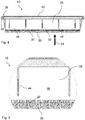
- FIG Figure 1 shows an isometric view of a filter element 10 without the pre-separator installed (30 in Figure 4 ) with filter bellows 12 molded in a frame 28 according to an embodiment of the invention.
- the filter element 10 for filtering a fluid comprises FIG Figure 1 a filter bellows 12 (alternatively: three filter bellows) with a designated raw side 52 and a designated clean side 50 opposite this, made of a filter medium 14 which is folded along fold edges 26 in a zigzag shape to form folds 34, each of which extends between opposite end edges 22a, 22b of the filter bellows 12 extend, and which in each case has end edge surfaces 20a, 20b running parallel to one another on opposite end faces 18, 19.
- the filter bellows 12 is molded with plastic in the form of a frame 28, so that the end edge surfaces 20a, 20b are sealed.
- the pre-separator (30 in Figure 4 ) can be fastened with fasteners 32 arranged on the frame 28, but is shown in FIG Figure 1 not shown.
- the frame 28 effects a side sealing of the end edge surfaces 20a, 20b.
- stiffening webs 42 are provided transversely to the folds 34, which at the same time serve as seals for the end edge surfaces 20a, 20b of the individual filter bellows 12.
- the frame 28 can advantageously consist of the same material as the filter medium 14 in order to achieve a material connection between the frame 28 and the filter bellows 12, as in the form of a weld.
- the fastening elements 32 are embodied in one piece with the frame 28, that is to say they are expediently produced together with the frame 28 in an injection molding process.
- the fastening elements 32 can also be formed only partially. They sit in particular on the underside of the side surfaces 46 and stiffening webs 42 of the frame 28, which at the same time form the sealing of the end edge surfaces 20a, 20b of the filter bellows 12.
- a circumferential seal 40 is provided on the end face 38 of the frame 28, which seal serves to separate the raw side 52 from the clean side 50 when used in a filter housing 108.
- the seal 40 can be molded onto the frame 28 in a two-component process. However, it can also be produced as a molded seal and pressed onto the frame 28 after it has been produced.
- FIG. 11 is an isometric view of the frame 28 without the filter bellows 12 according to the embodiment in FIG Figure 1 shown.
- the frame 28 can be seen as a framework for the filter bellows 12.
- the negative impressions of the end edges 22a, 22b of the filter bellows 12 can be seen in the side surfaces 46 and stiffening webs 42, since these are encapsulated with plastic and thus a side seal of the filter bellows 12 is achieved.
- the side surfaces 46 have stiffening ribs 44 for stiffening the entire frame 28.
- the fastening elements 32 for attaching the pre-separator 30 are arranged on the underside of the side surfaces 46 and stiffening webs 42.
- FIG 3 shows an isometric representation of a pre-separator 30 according to an embodiment of the invention in the form of a flat mat.
- the filter element 10 according to the invention in Figure 1 comprises such a pre-separator 30, which is designed as a flat mat and is arranged on the raw side 52 of the filter bellows 12.
- the pre-separator 30 is provided for joint exchange with the filter element 10. After the filter element 10 has been removed from a filter housing 108, the pre-separator 30 can be removed from the frame 28 in order to be cleaned or used again with another filter element 10.
- the filter element 10 can also be provided with a new pre-separator 30 so that it can continue to be used.
- An activated carbon medium can also be provided as the pre-separator 30.
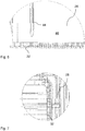
- FIG 4 is a side view of a filter element 10 can be seen with a pre-separator 30 according to an embodiment of the invention.
- the pre-separator 30 is attached to the fastening elements 32, which are located on the underside of the side surfaces 46 and stiffening webs (42 in Figure 1 ), which corresponds to the raw side 52 of the filter element 10, are attached.
- the direction of flow 54 of the filter element 10 is shown with an arrow.
- the seal 40 is arranged on a circumferential end face 38 of the frame 28 and is used for sealing between the raw side 52 and the clean side 50 when used in a filter housing 108.
- FIG. 10 shows an enlarged side view of the filter element 10 from FIG Figure 4 with detailing of the fastening elements 32 in the form of hook and loop fastener with attached pre-separator 30.
- the fastening elements 32 are designed as part of a hook and loop fastener, in particular as hook and loop fastener hooks.
- the pre-separator 30, which is designed as a fleece, for example, can be hooked into this hook-and-loop fastener as a counterpart of a Velcro fastener, which ensures a reliable and permanent connection between the frame 28 (FIG. 4) and the pre-separator 30 for the operation of the filter element 10. Nevertheless, when the filter element 10 is replaced, the pre-separator 30 can also be removed again and replaced.
- stiffening ribs 44 which serve to stiffen the side surfaces 46 of the frame 28, can also be clearly seen.
- FIG. 10 is an enlarged side view of the filter element 10 of FIG Figure 4 with detailing of the fastening elements 32 in the form of Velcro hooks without pre-separator 30.
- the shape of the Velcro hooks which can be produced in an injection molding process together with the frame 28 as a one-piece component, can be clearly seen.
- Such a shape can be represented in an injection mold. With such a mold, the finished component can also be removed from the mold after injection molding.
- the fastening elements 32 can also have a mushroom shape.
- Figure 7 shows a plan view of the fastening elements 32 in the form of Velcro hooks according to an embodiment of the invention.
- the in Figure 7 In the illustrated embodiment, a two-row arrangement of the Velcro hooks is chosen as sufficient for a permanent attachment of the pre-separator 30.
- FIG 8 shows a schematic sectional illustration of a filter system 100 according to an embodiment of the invention.
- the filter system 100 for filtering a fluid with a filter element 10 comprises an exchangeable filter element 10 arranged in a filter housing 108 of the filter system.
- the filter element 10 provides a filter bellows 12 and a pre-separator 30 for mutual exchange.
- the filter bellows 12 is molded with plastic in the form of a frame 28, so that the end edge surfaces 20a, 20b are sealed.
- the pre-separator 30 is fastened with fastening elements 32 arranged on the frame 28.
- the fastening elements 32 are formed in one piece with the frame 28.
- the fastening elements 32 are designed as part of a Velcro fastener, in particular as a Velcro fastener.
- the filter system 100 is used, for example, for air filtering, in particular for air filtering an internal combustion engine or as an interior filter of a vehicle.
- the filter housing 108 with the lower housing part 114 and the upper housing part 112 is shown purely schematically with an inlet 102 for the fluid and an outlet 104 for the fluid.
- the direction of flow 54 of the fluid is marked with an arrow.
- the filter element 10 inside the filter housing 108 is shown in side view and is sealed circumferentially against the filter housing 108 with the seal 40 on the end face 38 of the frame 28, so that the raw side 52 and clean side 50 are reliably separated.
- the pre-separator is arranged upstream of the raw side 52 of the filter bellows 12, which is molded in the frame 28, in order to effect a pre-separation of coarse dirt particles from the fluid.
Landscapes
- Chemical & Material Sciences (AREA)
- Engineering & Computer Science (AREA)
- Chemical Kinetics & Catalysis (AREA)
- Mechanical Engineering (AREA)
- Combustion & Propulsion (AREA)
- General Engineering & Computer Science (AREA)
- Analytical Chemistry (AREA)
- General Chemical & Material Sciences (AREA)
- Oil, Petroleum & Natural Gas (AREA)
- Filtering Of Dispersed Particles In Gases (AREA)
Claims (11)
- Élément filtrant (10) destiné à filtrer un fluide, comprenant- au moins un soufflet de filtre (12) avec un côté brut conforme à l'utilisation (52) et un côté pur conforme à l'utilisation (50) opposé au côté brut, constitué d'un milieu filtrant (14) plié le long d'arêtes de pliage (26) en plis (34) en zigzag qui s'étendent entre des arêtes frontales (22a, 22b) respectivement opposées du soufflet de filtre (12) et présentant sur les faces frontales (18, 19) respectivement opposées des surfaces d'arêtes frontales (20a, 20b) s'étendant parallèlement les unes aux autres,- au moins un pré-séparateur (30) qui est conçu en tant que natte plane et disposé sur le côté brut (52) du soufflet de filtre (12),dans lequel le soufflet de filtre (12) est enrobé de matière plastique sous la forme d'un cadre (28) de sorte que les surfaces d'arêtes frontales (20a, 20b) sont étanchées, et dans lequel le pré-séparateur (10) est attaché au moyen d'éléments de fixation (32) disposés sur le cadre (28), dans lequel les éléments de fixation (32) sont conçus d'un seul tenant avec le cadre (28),
caractérisé en ce que les éléments de fixation (32) sont conçus pour faire partie d'une fermeture Velcro. - Élément filtrant selon la revendication 1, dans lequel le cadre (28) réalise une étanchéité latérale des surfaces d'arêtes frontales (20a, 20b).
- Élément filtrant selon l'une des revendications précédentes, dans lequel les éléments de fixation (32) sont conçus en tant que crochets de fermeture Velcro.
- Élément filtrant selon l'une des revendications précédentes, dans lequel le pré-séparateur (30) est prévu à l'échange commun avec l'élément filtrant.
- Élément filtrant selon l'une des revendications précédentes, dans lequel un milieu de charbon actif est prévu comme pré-séparateur (30).
- Élément filtrant selon l'une des revendications précédentes, dans lequel le cadre (28) est fait du même matériau que le milieu filtrant (14).
- Élément filtrant selon l'une des revendications précédentes, dans lequel un joint d'étanchéité circonférentiel (40) est prévu sur la face frontale (38) du cadre (28).
- Elément filtrant selon l'une des revendications précédentes, dans lequel au moins une nervure de renforcement (42) est prévue dans le cadre (28) transversalement aux plis (34).
- Système de filtre (100) destiné à filtrer un fluide avec un élément filtrant (10) selon l'une des revendications précédentes, dans lequel l'élément filtrant (10) est disposé dans un boîtier de filtre (108) du système de filtre de manière échangeable, et lequel élément filtrant (10) est pourvu d'un soufflet de filtre (12) et d'un pré-séparateur (30) pour un échange commun, dans lequel le soufflet de filtre (12) est enrobé de matière plastique sous la forme d'un cadre (28) de sorte que les surfaces d'arêtes frontales (20a, 20b) sont étanchées, et dans lequel le pré-séparateur (30) est attaché au moyen d'éléments de fixation (32) disposés sur le cadre (28).
- Système de filtre selon la revendication 9, dans lequel les éléments de fixation (32) sont conçus en tant que crochets de fermeture Velcro.
- Utilisation du système de filtre (100) selon la revendication 9 ou 10 pour la filtration d'air pour un moteur à combustion interne ou en tant que filtre d'habitacle d'un véhicule.
Applications Claiming Priority (2)
| Application Number | Priority Date | Filing Date | Title |
|---|---|---|---|
| DE102015007901.8A DE102015007901A1 (de) | 2015-06-22 | 2015-06-22 | Filterelement mit Vorabscheider und Filtersystem |
| PCT/EP2016/060518 WO2016206855A1 (fr) | 2015-06-22 | 2016-05-11 | Élément filtrant muni d'un pré-séparateur et système de filtration |
Publications (2)
| Publication Number | Publication Date |
|---|---|
| EP3310454A1 EP3310454A1 (fr) | 2018-04-25 |
| EP3310454B1 true EP3310454B1 (fr) | 2021-01-13 |
Family
ID=55953170
Family Applications (1)
| Application Number | Title | Priority Date | Filing Date |
|---|---|---|---|
| EP16721442.8A Active EP3310454B1 (fr) | 2015-06-22 | 2016-05-11 | Élément filtrant muni d'un pré-séparateur et système de filtration |
Country Status (6)
| Country | Link |
|---|---|
| US (1) | US10589205B2 (fr) |
| EP (1) | EP3310454B1 (fr) |
| KR (1) | KR20180019601A (fr) |
| CN (1) | CN107810040B (fr) |
| DE (1) | DE102015007901A1 (fr) |
| WO (1) | WO2016206855A1 (fr) |
Families Citing this family (8)
| Publication number | Priority date | Publication date | Assignee | Title |
|---|---|---|---|---|
| DE102017011313A1 (de) * | 2017-12-08 | 2019-06-13 | Mann+Hummel Gmbh | Kraftfahrzeug mit Umgebungsluftreinigungsvorrichtung und Umgebungsluftreinigungsvorrichtung |
| DE102020121711A1 (de) * | 2020-08-19 | 2022-02-24 | Mann+Hummel Gmbh | Filterelement und Filtersystem |
| US20220314151A1 (en) * | 2021-04-06 | 2022-10-06 | K&N Engineering, Inc. | Multi-panel air filter |
| USD1085331S1 (en) * | 2021-10-18 | 2025-07-22 | Caterpillar Paving Products Inc. | Cooling package filter |
| EP4252887B1 (fr) * | 2022-03-28 | 2025-03-12 | MANN+HUMMEL GmbH | Système de filtre et élément de filtre |
| CN115138154A (zh) * | 2022-08-05 | 2022-10-04 | 安徽思诺特新材料科技有限公司 | 黏胶基石墨毡生产车间废气处理设备 |
| EP4474037B1 (fr) * | 2023-06-06 | 2025-12-03 | MANN+HUMMEL GmbH | Élément filtrant à filtre plat avec au moins deux corps de milieu filtrant, système filtrant et utilisation d'un élément filtrant à filtre plat |
| WO2026060160A1 (fr) * | 2024-09-11 | 2026-03-19 | Stryker Corporation | Ensemble filtre pour filtrer la fumée chirurgicale, et insert de filtre pour filtre à gaz de combustion |
Family Cites Families (8)
| Publication number | Priority date | Publication date | Assignee | Title |
|---|---|---|---|---|
| DE9405390U1 (de) * | 1994-03-30 | 1995-08-03 | Minnesota Mining And Manufacturing Co., Saint Paul, Minn. | Filteranordnung zum Filtern einer Fluidströmung |
| DE19534254A1 (de) | 1995-09-15 | 1997-03-20 | Mann & Hummel Filter | Filterelement |
| DE19700340A1 (de) * | 1997-01-08 | 1998-07-09 | Illbruck Industrieprodukte Gmb | Filter |
| US5730770A (en) * | 1997-01-17 | 1998-03-24 | Seh America, Inc. | Two-stage air filter for use with electronic enclosures |
| DE202009017970U1 (de) | 2009-09-14 | 2010-11-18 | Carl Freudenberg Kg | Tonerstaubfilter mit Flauschband |
| DE102010005114A1 (de) * | 2010-01-19 | 2011-07-21 | Mann + Hummel GmbH, 71638 | Filterelement und Filteranordnung |
| JPWO2012105208A1 (ja) * | 2011-01-31 | 2014-07-03 | パナソニック株式会社 | 集塵フィルターユニット、投写型画像表示装置、及び空気清浄機 |
| US8801826B2 (en) * | 2012-03-12 | 2014-08-12 | Bha Altair, Llc | Pre-filter or coalescer mounted on pulse cartridge tripod |
-
2015
- 2015-06-22 DE DE102015007901.8A patent/DE102015007901A1/de not_active Withdrawn
-
2016
- 2016-05-11 CN CN201680036947.5A patent/CN107810040B/zh active Active
- 2016-05-11 WO PCT/EP2016/060518 patent/WO2016206855A1/fr not_active Ceased
- 2016-05-11 KR KR1020177036891A patent/KR20180019601A/ko not_active Withdrawn
- 2016-05-11 EP EP16721442.8A patent/EP3310454B1/fr active Active
-
2017
- 2017-12-22 US US15/851,856 patent/US10589205B2/en active Active
Non-Patent Citations (1)
| Title |
|---|
| None * |
Also Published As
| Publication number | Publication date |
|---|---|
| EP3310454A1 (fr) | 2018-04-25 |
| CN107810040A (zh) | 2018-03-16 |
| US20180117514A1 (en) | 2018-05-03 |
| KR20180019601A (ko) | 2018-02-26 |
| WO2016206855A1 (fr) | 2016-12-29 |
| DE102015007901A1 (de) | 2016-12-22 |
| US10589205B2 (en) | 2020-03-17 |
| CN107810040B (zh) | 2020-09-01 |
Similar Documents
| Publication | Publication Date | Title |
|---|---|---|
| EP3310454B1 (fr) | Élément filtrant muni d'un pré-séparateur et système de filtration | |
| EP2582444B1 (fr) | Cartouche filtrante | |
| EP1679110A1 (fr) | Filtre à air | |
| DE102015011339B4 (de) | Filterelement mit einer umlaufenden Dichtung und Verfahren zu seiner Herstellung | |
| DE102012016955A1 (de) | Filteranordnung und Verfahren zum Herstellen einer Filteraufnahme | |
| DE102014000927A1 (de) | Filterelement | |
| DE202007014821U1 (de) | Filterelement V-Dichtung | |
| DE102013014489B4 (de) | Filterelement, Filtersystem mit einem Filterelement und Verwendung | |
| EP2029257B1 (fr) | Élément de filtre à air compact | |
| EP3043883B1 (fr) | Filtre à air | |
| EP3980158B1 (fr) | Élément filtrant et système de filtre | |
| EP1736227B1 (fr) | Système d'étanchéité d'un filtre | |
| EP3523010B1 (fr) | Élément filtrant, en particulier pour la filtration de gaz | |
| DE102016006073A1 (de) | Brennstoffzellen-Filterelement und Brennstoffzellen-Filtersystem mit einem Brennstoffzellen-Filterelement | |
| DE102017011876A1 (de) | Luftfilter mit integriertem Schneeschutz und Filterelement | |
| DE102014017785B4 (de) | Filteranordnung und Verwendung eines Filterelements | |
| DE202006020287U1 (de) | Filterelement mit tiefgezogenem Rahmen | |
| DE102007057616A1 (de) | Filtereinsatz und Filtereinrichtung | |
| EP2165067B1 (fr) | Dispositif de filtrage pour un système d'aspiration d'air | |
| EP4615609A1 (fr) | Appareil de filtration | |
| DE102012012940A1 (de) | Filterhalterahmen für ein Filtersystem | |
| WO2023143762A1 (fr) | Élément filtrant comprenant un milieu filtrant plié en forme de zigzag, et système de filtration | |
| WO2017220415A1 (fr) | Filtre d'habitacle et ensemble de filtration | |
| DE102008057300A1 (de) | Filterelement mit aufgespritzter Raupe | |
| DE102021126855A1 (de) | Filterelement und Filtersystem |
Legal Events
| Date | Code | Title | Description |
|---|---|---|---|
| STAA | Information on the status of an ep patent application or granted ep patent |
Free format text: STATUS: THE INTERNATIONAL PUBLICATION HAS BEEN MADE |
|
| PUAI | Public reference made under article 153(3) epc to a published international application that has entered the european phase |
Free format text: ORIGINAL CODE: 0009012 |
|
| STAA | Information on the status of an ep patent application or granted ep patent |
Free format text: STATUS: REQUEST FOR EXAMINATION WAS MADE |
|
| 17P | Request for examination filed |
Effective date: 20171110 |
|
| AK | Designated contracting states |
Kind code of ref document: A1 Designated state(s): AL AT BE BG CH CY CZ DE DK EE ES FI FR GB GR HR HU IE IS IT LI LT LU LV MC MK MT NL NO PL PT RO RS SE SI SK SM TR |
|
| AX | Request for extension of the european patent |
Extension state: BA ME |
|
| DAV | Request for validation of the european patent (deleted) | ||
| DAX | Request for extension of the european patent (deleted) | ||
| STAA | Information on the status of an ep patent application or granted ep patent |
Free format text: STATUS: EXAMINATION IS IN PROGRESS |
|
| 17Q | First examination report despatched |
Effective date: 20190802 |
|
| GRAP | Despatch of communication of intention to grant a patent |
Free format text: ORIGINAL CODE: EPIDOSNIGR1 |
|
| STAA | Information on the status of an ep patent application or granted ep patent |
Free format text: STATUS: GRANT OF PATENT IS INTENDED |
|
| INTG | Intention to grant announced |
Effective date: 20191112 |
|
| GRAJ | Information related to disapproval of communication of intention to grant by the applicant or resumption of examination proceedings by the epo deleted |
Free format text: ORIGINAL CODE: EPIDOSDIGR1 |
|
| STAA | Information on the status of an ep patent application or granted ep patent |
Free format text: STATUS: EXAMINATION IS IN PROGRESS |
|
| INTC | Intention to grant announced (deleted) | ||
| GRAP | Despatch of communication of intention to grant a patent |
Free format text: ORIGINAL CODE: EPIDOSNIGR1 |
|
| STAA | Information on the status of an ep patent application or granted ep patent |
Free format text: STATUS: GRANT OF PATENT IS INTENDED |
|
| INTG | Intention to grant announced |
Effective date: 20200819 |
|
| GRAS | Grant fee paid |
Free format text: ORIGINAL CODE: EPIDOSNIGR3 |
|
| GRAA | (expected) grant |
Free format text: ORIGINAL CODE: 0009210 |
|
| STAA | Information on the status of an ep patent application or granted ep patent |
Free format text: STATUS: THE PATENT HAS BEEN GRANTED |
|
| AK | Designated contracting states |
Kind code of ref document: B1 Designated state(s): AL AT BE BG CH CY CZ DE DK EE ES FI FR GB GR HR HU IE IS IT LI LT LU LV MC MK MT NL NO PL PT RO RS SE SI SK SM TR |
|
| REG | Reference to a national code |
Ref country code: GB Ref legal event code: FG4D Free format text: NOT ENGLISH |
|
| REG | Reference to a national code |
Ref country code: CH Ref legal event code: EP |
|
| REG | Reference to a national code |
Ref country code: IE Ref legal event code: FG4D Free format text: LANGUAGE OF EP DOCUMENT: GERMAN |
|
| REG | Reference to a national code |
Ref country code: DE Ref legal event code: R096 Ref document number: 502016012191 Country of ref document: DE |
|
| REG | Reference to a national code |
Ref country code: AT Ref legal event code: REF Ref document number: 1354128 Country of ref document: AT Kind code of ref document: T Effective date: 20210215 |
|
| RAP4 | Party data changed (patent owner data changed or rights of a patent transferred) |
Owner name: MANN+HUMMEL GMBH |
|
| REG | Reference to a national code |
Ref country code: NL Ref legal event code: MP Effective date: 20210113 |
|
| REG | Reference to a national code |
Ref country code: LT Ref legal event code: MG9D |
|
| PG25 | Lapsed in a contracting state [announced via postgrant information from national office to epo] |
Ref country code: FI Free format text: LAPSE BECAUSE OF FAILURE TO SUBMIT A TRANSLATION OF THE DESCRIPTION OR TO PAY THE FEE WITHIN THE PRESCRIBED TIME-LIMIT Effective date: 20210113 Ref country code: HR Free format text: LAPSE BECAUSE OF FAILURE TO SUBMIT A TRANSLATION OF THE DESCRIPTION OR TO PAY THE FEE WITHIN THE PRESCRIBED TIME-LIMIT Effective date: 20210113 Ref country code: GR Free format text: LAPSE BECAUSE OF FAILURE TO SUBMIT A TRANSLATION OF THE DESCRIPTION OR TO PAY THE FEE WITHIN THE PRESCRIBED TIME-LIMIT Effective date: 20210414 Ref country code: PT Free format text: LAPSE BECAUSE OF FAILURE TO SUBMIT A TRANSLATION OF THE DESCRIPTION OR TO PAY THE FEE WITHIN THE PRESCRIBED TIME-LIMIT Effective date: 20210513 Ref country code: NO Free format text: LAPSE BECAUSE OF FAILURE TO SUBMIT A TRANSLATION OF THE DESCRIPTION OR TO PAY THE FEE WITHIN THE PRESCRIBED TIME-LIMIT Effective date: 20210413 Ref country code: LT Free format text: LAPSE BECAUSE OF FAILURE TO SUBMIT A TRANSLATION OF THE DESCRIPTION OR TO PAY THE FEE WITHIN THE PRESCRIBED TIME-LIMIT Effective date: 20210113 Ref country code: BG Free format text: LAPSE BECAUSE OF FAILURE TO SUBMIT A TRANSLATION OF THE DESCRIPTION OR TO PAY THE FEE WITHIN THE PRESCRIBED TIME-LIMIT Effective date: 20210413 |
|
| PG25 | Lapsed in a contracting state [announced via postgrant information from national office to epo] |
Ref country code: SE Free format text: LAPSE BECAUSE OF FAILURE TO SUBMIT A TRANSLATION OF THE DESCRIPTION OR TO PAY THE FEE WITHIN THE PRESCRIBED TIME-LIMIT Effective date: 20210113 Ref country code: LV Free format text: LAPSE BECAUSE OF FAILURE TO SUBMIT A TRANSLATION OF THE DESCRIPTION OR TO PAY THE FEE WITHIN THE PRESCRIBED TIME-LIMIT Effective date: 20210113 Ref country code: PL Free format text: LAPSE BECAUSE OF FAILURE TO SUBMIT A TRANSLATION OF THE DESCRIPTION OR TO PAY THE FEE WITHIN THE PRESCRIBED TIME-LIMIT Effective date: 20210113 Ref country code: RS Free format text: LAPSE BECAUSE OF FAILURE TO SUBMIT A TRANSLATION OF THE DESCRIPTION OR TO PAY THE FEE WITHIN THE PRESCRIBED TIME-LIMIT Effective date: 20210113 |
|
| PG25 | Lapsed in a contracting state [announced via postgrant information from national office to epo] |
Ref country code: IS Free format text: LAPSE BECAUSE OF FAILURE TO SUBMIT A TRANSLATION OF THE DESCRIPTION OR TO PAY THE FEE WITHIN THE PRESCRIBED TIME-LIMIT Effective date: 20210513 |
|
| REG | Reference to a national code |
Ref country code: DE Ref legal event code: R097 Ref document number: 502016012191 Country of ref document: DE |
|
| PG25 | Lapsed in a contracting state [announced via postgrant information from national office to epo] |
Ref country code: EE Free format text: LAPSE BECAUSE OF FAILURE TO SUBMIT A TRANSLATION OF THE DESCRIPTION OR TO PAY THE FEE WITHIN THE PRESCRIBED TIME-LIMIT Effective date: 20210113 Ref country code: CZ Free format text: LAPSE BECAUSE OF FAILURE TO SUBMIT A TRANSLATION OF THE DESCRIPTION OR TO PAY THE FEE WITHIN THE PRESCRIBED TIME-LIMIT Effective date: 20210113 Ref country code: SM Free format text: LAPSE BECAUSE OF FAILURE TO SUBMIT A TRANSLATION OF THE DESCRIPTION OR TO PAY THE FEE WITHIN THE PRESCRIBED TIME-LIMIT Effective date: 20210113 |
|
| PLBE | No opposition filed within time limit |
Free format text: ORIGINAL CODE: 0009261 |
|
| STAA | Information on the status of an ep patent application or granted ep patent |
Free format text: STATUS: NO OPPOSITION FILED WITHIN TIME LIMIT |
|
| PG25 | Lapsed in a contracting state [announced via postgrant information from national office to epo] |
Ref country code: SK Free format text: LAPSE BECAUSE OF FAILURE TO SUBMIT A TRANSLATION OF THE DESCRIPTION OR TO PAY THE FEE WITHIN THE PRESCRIBED TIME-LIMIT Effective date: 20210113 Ref country code: RO Free format text: LAPSE BECAUSE OF FAILURE TO SUBMIT A TRANSLATION OF THE DESCRIPTION OR TO PAY THE FEE WITHIN THE PRESCRIBED TIME-LIMIT Effective date: 20210113 Ref country code: DK Free format text: LAPSE BECAUSE OF FAILURE TO SUBMIT A TRANSLATION OF THE DESCRIPTION OR TO PAY THE FEE WITHIN THE PRESCRIBED TIME-LIMIT Effective date: 20210113 |
|
| 26N | No opposition filed |
Effective date: 20211014 |
|
| REG | Reference to a national code |
Ref country code: CH Ref legal event code: PL |
|
| GBPC | Gb: european patent ceased through non-payment of renewal fee |
Effective date: 20210511 |
|
| PG25 | Lapsed in a contracting state [announced via postgrant information from national office to epo] |
Ref country code: ES Free format text: LAPSE BECAUSE OF FAILURE TO SUBMIT A TRANSLATION OF THE DESCRIPTION OR TO PAY THE FEE WITHIN THE PRESCRIBED TIME-LIMIT Effective date: 20210113 Ref country code: AL Free format text: LAPSE BECAUSE OF FAILURE TO SUBMIT A TRANSLATION OF THE DESCRIPTION OR TO PAY THE FEE WITHIN THE PRESCRIBED TIME-LIMIT Effective date: 20210113 Ref country code: CH Free format text: LAPSE BECAUSE OF NON-PAYMENT OF DUE FEES Effective date: 20210531 Ref country code: LI Free format text: LAPSE BECAUSE OF NON-PAYMENT OF DUE FEES Effective date: 20210531 Ref country code: MC Free format text: LAPSE BECAUSE OF FAILURE TO SUBMIT A TRANSLATION OF THE DESCRIPTION OR TO PAY THE FEE WITHIN THE PRESCRIBED TIME-LIMIT Effective date: 20210113 Ref country code: LU Free format text: LAPSE BECAUSE OF NON-PAYMENT OF DUE FEES Effective date: 20210511 |
|
| REG | Reference to a national code |
Ref country code: BE Ref legal event code: MM Effective date: 20210531 |
|
| PG25 | Lapsed in a contracting state [announced via postgrant information from national office to epo] |
Ref country code: SI Free format text: LAPSE BECAUSE OF FAILURE TO SUBMIT A TRANSLATION OF THE DESCRIPTION OR TO PAY THE FEE WITHIN THE PRESCRIBED TIME-LIMIT Effective date: 20210113 |
|
| PG25 | Lapsed in a contracting state [announced via postgrant information from national office to epo] |
Ref country code: IT Free format text: LAPSE BECAUSE OF FAILURE TO SUBMIT A TRANSLATION OF THE DESCRIPTION OR TO PAY THE FEE WITHIN THE PRESCRIBED TIME-LIMIT Effective date: 20210113 Ref country code: IE Free format text: LAPSE BECAUSE OF NON-PAYMENT OF DUE FEES Effective date: 20210511 Ref country code: GB Free format text: LAPSE BECAUSE OF NON-PAYMENT OF DUE FEES Effective date: 20210511 |
|
| PG25 | Lapsed in a contracting state [announced via postgrant information from national office to epo] |
Ref country code: IS Free format text: LAPSE BECAUSE OF FAILURE TO SUBMIT A TRANSLATION OF THE DESCRIPTION OR TO PAY THE FEE WITHIN THE PRESCRIBED TIME-LIMIT Effective date: 20210513 Ref country code: FR Free format text: LAPSE BECAUSE OF NON-PAYMENT OF DUE FEES Effective date: 20210531 |
|
| REG | Reference to a national code |
Ref country code: AT Ref legal event code: MM01 Ref document number: 1354128 Country of ref document: AT Kind code of ref document: T Effective date: 20210511 |
|
| PG25 | Lapsed in a contracting state [announced via postgrant information from national office to epo] |
Ref country code: BE Free format text: LAPSE BECAUSE OF NON-PAYMENT OF DUE FEES Effective date: 20210531 |
|
| PG25 | Lapsed in a contracting state [announced via postgrant information from national office to epo] |
Ref country code: AT Free format text: LAPSE BECAUSE OF NON-PAYMENT OF DUE FEES Effective date: 20210511 |
|
| PG25 | Lapsed in a contracting state [announced via postgrant information from national office to epo] |
Ref country code: NL Free format text: LAPSE BECAUSE OF NON-PAYMENT OF DUE FEES Effective date: 20210113 Ref country code: CY Free format text: LAPSE BECAUSE OF FAILURE TO SUBMIT A TRANSLATION OF THE DESCRIPTION OR TO PAY THE FEE WITHIN THE PRESCRIBED TIME-LIMIT Effective date: 20210113 |
|
| PG25 | Lapsed in a contracting state [announced via postgrant information from national office to epo] |
Ref country code: HU Free format text: LAPSE BECAUSE OF FAILURE TO SUBMIT A TRANSLATION OF THE DESCRIPTION OR TO PAY THE FEE WITHIN THE PRESCRIBED TIME-LIMIT; INVALID AB INITIO Effective date: 20160511 |
|
| PG25 | Lapsed in a contracting state [announced via postgrant information from national office to epo] |
Ref country code: MK Free format text: LAPSE BECAUSE OF FAILURE TO SUBMIT A TRANSLATION OF THE DESCRIPTION OR TO PAY THE FEE WITHIN THE PRESCRIBED TIME-LIMIT Effective date: 20210113 |
|
| PG25 | Lapsed in a contracting state [announced via postgrant information from national office to epo] |
Ref country code: TR Free format text: LAPSE BECAUSE OF FAILURE TO SUBMIT A TRANSLATION OF THE DESCRIPTION OR TO PAY THE FEE WITHIN THE PRESCRIBED TIME-LIMIT Effective date: 20210113 |
|
| PG25 | Lapsed in a contracting state [announced via postgrant information from national office to epo] |
Ref country code: MT Free format text: LAPSE BECAUSE OF FAILURE TO SUBMIT A TRANSLATION OF THE DESCRIPTION OR TO PAY THE FEE WITHIN THE PRESCRIBED TIME-LIMIT Effective date: 20210113 |
|
| PGFP | Annual fee paid to national office [announced via postgrant information from national office to epo] |
Ref country code: DE Payment date: 20250521 Year of fee payment: 10 |