EP3310509B1 - Hubkolben-verbrennungskraftmaschine und verfahren zum herstellen einer hubkolben-verbrennungskraftmaschine - Google Patents
Hubkolben-verbrennungskraftmaschine und verfahren zum herstellen einer hubkolben-verbrennungskraftmaschine Download PDFInfo
- Publication number
- EP3310509B1 EP3310509B1 EP16754390.9A EP16754390A EP3310509B1 EP 3310509 B1 EP3310509 B1 EP 3310509B1 EP 16754390 A EP16754390 A EP 16754390A EP 3310509 B1 EP3310509 B1 EP 3310509B1
- Authority
- EP
- European Patent Office
- Prior art keywords
- crankcase
- assembly
- cylinder head
- composite
- cylinders
- Prior art date
- Legal status (The legal status is an assumption and is not a legal conclusion. Google has not performed a legal analysis and makes no representation as to the accuracy of the status listed.)
- Active
Links
Images





Classifications
-
- F—MECHANICAL ENGINEERING; LIGHTING; HEATING; WEAPONS; BLASTING
- F02—COMBUSTION ENGINES; HOT-GAS OR COMBUSTION-PRODUCT ENGINE PLANTS
- F02F—CYLINDERS, PISTONS OR CASINGS, FOR COMBUSTION ENGINES; ARRANGEMENTS OF SEALINGS IN COMBUSTION ENGINES
- F02F1/00—Cylinders; Cylinder heads
- F02F1/02—Cylinders; Cylinder heads having cooling means
- F02F1/10—Cylinders; Cylinder heads having cooling means for liquid cooling
- F02F1/102—Attachment of cylinders to crankcase
-
- B—PERFORMING OPERATIONS; TRANSPORTING
- B22—CASTING; POWDER METALLURGY
- B22D—CASTING OF METALS; CASTING OF OTHER SUBSTANCES BY THE SAME PROCESSES OR DEVICES
- B22D19/00—Casting in, on, or around objects which form part of the product
- B22D19/0009—Cylinders, pistons
-
- F—MECHANICAL ENGINEERING; LIGHTING; HEATING; WEAPONS; BLASTING
- F02—COMBUSTION ENGINES; HOT-GAS OR COMBUSTION-PRODUCT ENGINE PLANTS
- F02F—CYLINDERS, PISTONS OR CASINGS, FOR COMBUSTION ENGINES; ARRANGEMENTS OF SEALINGS IN COMBUSTION ENGINES
- F02F1/00—Cylinders; Cylinder heads
- F02F1/02—Cylinders; Cylinder heads having cooling means
- F02F1/10—Cylinders; Cylinder heads having cooling means for liquid cooling
- F02F1/108—Siamese-type cylinders, i.e. cylinders cast together
-
- F—MECHANICAL ENGINEERING; LIGHTING; HEATING; WEAPONS; BLASTING
- F02—COMBUSTION ENGINES; HOT-GAS OR COMBUSTION-PRODUCT ENGINE PLANTS
- F02F—CYLINDERS, PISTONS OR CASINGS, FOR COMBUSTION ENGINES; ARRANGEMENTS OF SEALINGS IN COMBUSTION ENGINES
- F02F1/00—Cylinders; Cylinder heads
- F02F1/24—Cylinder heads
-
- F—MECHANICAL ENGINEERING; LIGHTING; HEATING; WEAPONS; BLASTING
- F02—COMBUSTION ENGINES; HOT-GAS OR COMBUSTION-PRODUCT ENGINE PLANTS
- F02F—CYLINDERS, PISTONS OR CASINGS, FOR COMBUSTION ENGINES; ARRANGEMENTS OF SEALINGS IN COMBUSTION ENGINES
- F02F7/00—Casings, e.g. crankcases
- F02F7/0002—Cylinder arrangements
-
- F—MECHANICAL ENGINEERING; LIGHTING; HEATING; WEAPONS; BLASTING
- F02—COMBUSTION ENGINES; HOT-GAS OR COMBUSTION-PRODUCT ENGINE PLANTS
- F02F—CYLINDERS, PISTONS OR CASINGS, FOR COMBUSTION ENGINES; ARRANGEMENTS OF SEALINGS IN COMBUSTION ENGINES
- F02F7/00—Casings, e.g. crankcases
- F02F7/0021—Construction
-
- F—MECHANICAL ENGINEERING; LIGHTING; HEATING; WEAPONS; BLASTING
- F02—COMBUSTION ENGINES; HOT-GAS OR COMBUSTION-PRODUCT ENGINE PLANTS
- F02F—CYLINDERS, PISTONS OR CASINGS, FOR COMBUSTION ENGINES; ARRANGEMENTS OF SEALINGS IN COMBUSTION ENGINES
- F02F7/00—Casings, e.g. crankcases
- F02F7/0085—Materials for constructing engines or their parts
-
- F—MECHANICAL ENGINEERING; LIGHTING; HEATING; WEAPONS; BLASTING
- F02—COMBUSTION ENGINES; HOT-GAS OR COMBUSTION-PRODUCT ENGINE PLANTS
- F02F—CYLINDERS, PISTONS OR CASINGS, FOR COMBUSTION ENGINES; ARRANGEMENTS OF SEALINGS IN COMBUSTION ENGINES
- F02F2200/00—Manufacturing
- F02F2200/06—Casting
Definitions
- the present invention relates to a reciprocating internal combustion engine and a method for manufacturing a reciprocating internal combustion engine.
- crankcases have intricate internal spaces which, in the finishing process, require complicated cleaning to remove the sand and / or silt residue from the foundry process.
- cylinder crankcases today have a variety of integrated molded internal functions, such as water jackets, passages and channels for water or oil, which must be cleaned after casting. To make matters worse, that for engine components, the requirements for component cleanliness and the residual dirt requirements have risen sharply in recent times.
- centrifugal blast machines are used for cleaning, which essentially clean the outer contours of residues of the casting process.
- Inner contours are usually cleaned with pressure blast equipment, whereby the hand process and type-specific special machines dominate because of the complex interiors.
- Reciprocating internal combustion engines comprising a cylinder head, a crankcase and a composite, wherein the outer wall portions of the cylinder of the composite and the wall portions of the recess for receiving the composite of the crankcase form a coolant space, are for example from US 3,168,081 A and US 2006/037566 A1 known.
- a reciprocating internal combustion engine comprising a cylinder head, a crankcase and a composite
- the crankcase comprises a recess for receiving the composite
- the composite comprises at least two cylinders and a plate-shaped cylinder head bearing surface connecting them, wherein the composite is formed in one piece
- the plate-shaped cylinder head support surface has a recess for each cylinder and wherein the composite is insertable into a crankcase of a reciprocating internal combustion engine or can be placed on a crankcase of a reciprocating internal combustion engine and wherein the bond between the cylinder head and the crankcase and in the recess for receiving the composite is arranged and wherein the outer wall portions of the cylinder of the composite and the wall portions of the recess for receiving the composite of the crankcase form a coolant space, achieved in that at least a coolant guide is arranged between the cylinders of the assembly, wherein the coolant guide of the composite is realized by drilling through the intermediate region of two adjacent cylinders and / or by
- a composite is arranged, wherein the composite is integrally formed and is inserted into a crankcase of a reciprocating internal combustion engine or placed with the plate-shaped cylinder head bearing surface on the crankcase and with the Cylinders is inserted into the recess of the crankcase for receiving the cylinders of the composite, and wherein the plate-shaped cylinder head support surface is for supporting the cylinder head and has a recess for each cylinder.
- a coolant guide is arranged between the cylinders, wherein the coolant guide by drilling through the intermediate region of two adjacent, possibly connected cylinder and / or by a cooling channel core in the intermediate region of two adjacent, possibly connected, cylinder is realized.
- the water jacket geometry will have a thickness of less than 5mm, preferably less than 3.5mm.
- the at least two cylinders connecting plate-shaped cylinder head bearing surface is placed on the crankcase or inserted into the recess for receiving the composite.
- mounted means that the cylinder head bearing surface covers or overlaps the recess of the crankcase.
- Unsed in this context means that the cylinder head bearing surface can be positively inserted into the recess of the crankcase.
- the recess of the crankcase may have at least one inwardly directed at least partially circumferential projection or seat, so that the outer region of the cylinder head bearing surface can rest on the projection or seat.
- the recess of the crankcase for receiving the composite in its geometry is designed such that the composite at least partially, at least the cylinder, can be arranged in the crankcase.
- the recess for receiving the composite corresponds in its internal geometry of the outer geometry of the at least two cylinders.
- the cylinders can therefore be accurately inserted into the crankcase.
- the recess for receiving the composite in its upper inner geometry corresponds to the outer geometry of the plate-shaped cylinder head bearing surface, wherein it can be provided that the plate-shaped cylinder head support surface is held by a circumferential projection in the recess.
- crankcase By a separate production of the composite and the "open" crankcase, there are further advantages for the production of the crankcase. For example, a significantly simplified accessibility for component-internal supply measures is achieved, whereby the structure in the bearing block area can be positively influenced by the use of cooling elements with regard to the resulting mechanical properties. Furthermore, it is advantageous that the cleaning of the "open" crankcase is simplified, whereby the residual dirt requirements can be met much easier.
- crankcase according to the invention can be produced in a cost-effective and easy-to-control alloys requirements.
- tread coatings for example, the masking (cover) to avoid overspray and additional cleaning steps after spraying in the crankcase area can be omitted.
- the one-piece design of the multi-cylinder composite advantageously ensures that the composite can be produced as a separate component.
- Various methods can be used for the production.
- the component is cast.
- the production of the composite is achieved by a deep-drawing process or the forging of the composite using, for example, aluminum-copper wrought alloys.
- the plate-shaped cylinder head bearing surface of the multi-cylinder composite that this is free formable in its geometry.
- the thickness of the plate-shaped cylinder head bearing surface can be produced according to the resulting loads.
- the plate-shaped cylinder head bearing surface has greater thicknesses in loaded areas and minimum thicknesses in unloaded areas.
- the geometry of the plate-shaped cylinder head bearing surface can be freely designed, for example such that the plate-shaped cylinder head bearing surface is adapted to the geometry of the crankcase and the cylinder head.
- the outer cylinder walls can be freely designed according to the requirements.
- a force flow and / or requirement-optimized support structure such as rib reinforcements and the like or cooling ribs, can be realized on the outer cylinder walls.
- the support structure (ribs) is arranged on the cylinder walls such that a flow optimization is achieved.
- the support structure (ribs) is already produced in the production of the cylinder.
- At least one coolant guide or web cooling is arranged between the cylinders.
- the composite with its cylinder geometries and the plate-shaped cylinder head bearing surface is not produced together with the cylinder crankcase, but separately manufactured and can be used in this or placed on this (the plate-shaped cylinder head bearing surface rests on the crankcase, wherein the cylinders protrude into the crankcase), can the coolant supply very universal, individual and without restrictions regarding position, eg also directly below and parallel to the cylinder head bearing surface, are produced.
- the cylinders there is at least one recess between at least two adjacent cylinders so that coolant can pass from one side of the composite through the recess onto the opposite side of the assembly. Accordingly, the cylinders are also cooled in the area between the cylinders. It can be provided that a coolant guide is arranged between all adjacent cylinders. Likewise it can be provided that the coolant guide only between some cylinders, e.g. in every second area between two adjacent cylinders.
- the cylinder tube shape and cylinder tube wall can be freely designed according to the requirements.
- the design of the cylinder tube shape is important to counteract the deformation by the screw.
- the cylinder tube wall may be convex (arched outward), concave (inwardly curved), sinusoidal, step-shaped, or as a mixture of the foregoing be configured or provided with support structures, cooling fins or the like.
- the formable cylinder tube shape and cylinder tube wall have the advantage that the cylinder wall thickness can be increased in the range of high ignition pressures.
- a flow optimization can be achieved. For example, a higher flow rate is made possible by a customized design.
- crankcase can be made as an "open" crankcase and the cylinder can before the insertion can be easily edited, which allows a great deal of freedom in the design of the cylinder outer wall.
- crankcase internal feeds such as nonferrous alloys or iron base materials
- the invention also allows the currently very much sought after, completely separate coolant management of the cylinder head and crankcase, since no openings for storage of the usual water jacket or Losteilschieber are required. So a closed head area is possible.
- the plate-shaped cylinder head bearing surface can also, depending on requirements, be opened locally to allow a connection between the coolant chamber and water space of the crankcase to the coolant chamber and water space of the head.
- the plate-shaped cylinder head bearing surface is configured in its dimensions such that it is largely introduced positively into the open crankcase.
- An embodiment of the invention provides that the outer wall of the cylinder have at least one horizontally at least partially encircling bead.
- the bead is preferably formed as a sealing bead.
- the sealing bead is preferably arranged on the cylinder such that a seal between a coolant space or water space (formed by the outer walls of the cylinders and the upper inner walls of the crankcase) and the lower crankcase is achieved.
- the composite thus offers the described advantages the possibility of improving internal combustion engines for current and future higher ignition pressures and higher temperature loads in the top plate and cylinder land, and cylinder tube.
- the composite according to the invention can be used to solve the challenges with regard to thermal shock resistance, thermal stress on the cylinder web ("gusset"), tribology, plate stiffness and stiffness, cylinder distortion, coatability of the raceways (in the case of Al-Leg.).
- the plate-shaped cylinder head bearing surface of the composite to the recesses for each cylinder - is formed without passage.
- this configuration it is achieved that the rigidity and structure of the cylinder head bearing surface is not weakened by passages. This also allows a simplified sealing between the cylinder head and the cylinder crankcase, since no / hardly any spills, stoppers, etc. are arranged when using a head gasket on the cylinder head bearing surface. Advantageously, this configuration further ensures that the internal combustion engine can be exposed to higher pressures. Likewise, the tendency for cracking of the cylinder head bearing surface, which is favored by passages as an initial location, can be reduced to prevented.
- the composite is further advantageous provided that the composite of cast iron with lamellar graphite (GJL), cast iron with vermicular graphite (GJV), cast iron with nodular graphite (GJS) and / or steel and / or a combination of the aforementioned materials is made.
- GJL lamellar graphite
- GJV vermicular graphite
- GJS cast iron with nodular graphite
- the production of the internal combustion engine as a whole can be simplified, for example by casting. It is also achieved that a requirement-optimized control of the fine grain and the freedom from pores of the cylinder tube structure is made possible by the separate production without the crankcase being influenced. For example, a quenching layer can be realized close to the surface of the tread. Likewise or additionally, a continuously quenched cylinder wall can be realized. This separate treatment of the composite enables improved heat conduction and transfer into the cooling circuit as well as adjustability of the mechanical properties (tensile strength R m , yield strength R p0.2 and elongation at break A ).
- the composite of non-ferrous materials especially aluminum alloys, such as aluminum-magnesium alloys (AlMgxx), aluminum-silicon alloys (AlSixx) with copper (Cu) and / or magnesium (Mg) and or aluminum wrought alloys, is produced.
- aluminum alloys such as aluminum-magnesium alloys (AlMgxx), aluminum-silicon alloys (AlSixx) with copper (Cu) and / or magnesium (Mg) and or aluminum wrought alloys
- non-ferrous materials By using non-ferrous materials to make the composite, it can be made without feeding. In particular, it is advantageous that a subsequent liner encapsulation and the subsequent joining of the liner omitted. It is particularly advantageous that only the composite of non-ferrous materials, in particular aluminum alloys, is produced, and not the complete cylinder crankcase (composite and "open" crankcase).
- Non-ferrous materials especially those based on aluminum, make it possible to produce a coatable running surface by using cooling elements in the cylinder tube (steel molds, GJL, Ms, etc.) without affecting the crankcase.
- a cooling groove is arranged on the cylinder head side facing the cylinder head bearing surface, which serves to reduce the temperatures in the web area. It is further provided that the cooling groove is supplied by the cylinder head with coolant.
- a reciprocating internal combustion engine comprising a cylinder head, a crankcase and an integrally formed from a cylinder and a cylinder head bearing surface composite, wherein the plate-shaped cylinder head bearing surface has a recess for the one cylinder and wherein the crankcase a recess for receiving the one piece of a cylinder and a cylinder head bearing surface formed composite shown, in which a portion of the cylinder outer wall of the composite and the recess of the crankcase for receiving the composite form a coolant space or water space.
- the composite described here consists of exactly one cylinder and one cylinder head bearing surface.
- the cylinder head bearing surface may be configured according to the multi-cylinder composite. It is also contemplated that the single-cylinder composite may be made of the same materials as the multi-cylinder composite.
- the object is also achieved by a method for producing the reciprocating internal combustion engine.
- connection of the crankcase, the composite and the cylinder head by common methods such as screws, gluing, clamping, sealing or the like is achieved. Due to the one-piece design of the composite, it is advantageously achieved that the cylinders are hardly or not distorted when joining, since the force flow during connection (for example, by tightening cylinder head bolts) is decoupled from the cylinder ears. Due to the configuration, a slimmer cylinder wall can be further realized, which leads to a weight and thus cost reduction.
- Fig. 1 is a composite (1) of four cylinders (2a, 2b, 2c, 2d) and a plate-shaped cylinder head bearing surface (5) connecting these cylinders, wherein the composite (1) consists of at least two cylinders (2a, 2b, 2c, 2d) and the this connecting plate-shaped cylinder head bearing surface (5) is integrally formed, shown in perspective view.
- the plate-shaped cylinder head bearing surface (5) for each cylinder (2a; 2b; 2c; 2d) has a recess (3a; 3b; 3c; 3d).
- the composite (1) in a ("open") crankcase (7a, 7b) of a reciprocating internal combustion engine can be used or placed on this.
- the plate-shaped cylinder head bearing surface (5) - with the exception of the recesses (3a; 3b; 3c; 3d) - has a passage-free design for each cylinder (2a; 2b; 2c; 2d).
- Fig. 2 shows the composite (1) of four cylinders and a connecting them plate-shaped cylinder head support surface (5) in, in comparison to Fig. 1 inverted, perspective view. Since the composite (1) is manufactured separately, it is made possible by the use of cooling elements in the cylinder tube (steel molds, GJL, Ms, ...) a coatable tread (4a, 4b, 4c, 4d) can be produced, without affecting the crankcase. It is also achieved that a requirement-optimized control of the fine grain and the freedom from pores of the cylinder tube structure is made possible by the separate production without the crankcase being influenced. For example, a quenching layer can be realized close to the surface of the tread. Likewise or additionally, a continuously quenched cylinder wall can be realized.
- the composite (1) of four cylinders (2a, 2b, 2c, 2d) and a plate-shaped cylinder head bearing surface connecting them is shown in vertical sectional views.
- the coolant guide (6) can be realized by drilling through the intermediate region of two adjacent longitudinally connected cylinders (2a, 2b, 2c, 2d).
- the coolant guide (6) can be realized by a cooling channel core in the intermediate region of two adjacent longitudinally connected cylinders (2a, 2b, 2c, 2d).
- Fig. 3c it is shown that the coolant guide (6) can be realized by freestanding cylinders (2a; 2b; 2c; 2d).
- a cooling groove (6a) is disposed in the plate-shaped cylinder head support surface.
- the geometry, shape and position of the cooling groove (6a) are not limited to the illustrated gap-like embodiment, but may be arranged on the cylinder head bearing surface according to need.
- Fig. 4 shows a reciprocating internal combustion engine according to the invention, comprising a cylinder head (8) and a crankcase (7a) according to the invention, wherein between the cylinder head (8) and the crankcase (7a) a composite (1) of four cylinders and a four-cylinder connecting plate-shaped cylinder head bearing surface is arranged, in exploded view.
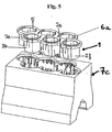
- Fig. 5 is a composite (1, VR6 inline variant) and a corresponding open crankcase (7c, VR6 inline crankcase) in an exploded view.
- the composite (1) comprises six cylinders (2, 2b, 2c, 2d, 2e, 2f) and a plate-shaped cylinder head bearing surface (5) connecting these cylinders.
- the composite (1) is configured to be inserted into the crankcase (7c) (the plate-shaped cylinder head support surface can be approximately positively fitted on a seat in the crankcase, the cylinders are guided in the crankcase).
- the cylinders are offset from each other in the longitudinal direction and each have a setting (to the longitudinal axis) of about 15%.
- the cylinders (2, 2b, 2c, 2d, 2e, 2f) can be freely guided in the crankcase (7c).
- the inner contour of the recess of the crankcase (for receiving the composite) may be substantially smooth or, as shown here, have a contour.
- cooling grooves (6a) are shown on the plate-shaped cylinder head support surface (5).
- the cooling grooves (6a) are at least partially arranged radially circumferentially around the recesses for the cylinder, wherein the shape, the size, the number, the depth and the position are freely designable.
- Fig. 6 shows an inventive reciprocating internal combustion engine in exploded view.
- the reciprocating internal combustion engine comprises a cylinder head (8) and a crankcase (7a), wherein between the cylinder head (8) and the crankcase (7a) a composite (1) of four cylinders and a plate-shaped cylinder head support surface connecting these four cylinders is arranged.
- the composite (1) is mounted on the crankcase (7a) (the plate-shaped cylinder head bearing surface rests on the crankcase, the cylinders are guided in the crankcase).
- On the plate-shaped cylinder head support surface three cooling grooves (6a) are shown.
- the cooling grooves (6a) are arranged between the recesses for the cylinder.
- Fig. 7 shows an inventive reciprocating internal combustion engine in exploded view.
- the reciprocating internal combustion engine comprises a cylinder head (8) and a crankcase (7a), wherein between the cylinder head (8) and the crankcase (7a) a composite (1) of four cylinders and a plate-shaped cylinder head support surface connecting these four cylinders is arranged.
- the composite (1) is positively inserted into the crankcase (the plate-shaped cylinder head bearing surface rests on a shoulder in the crankcase, so that the cylinder head bearing surface and the top of the crankcase in the assembled state are flat; are guided in the crankcase).
- Fig. 8 is a composite (1) of four cylinders and a cylinder-connecting these cylinder plate-shaped surface, wherein the composite (1) is integrally formed, shown in a perspective view.
- the outer walls of the cylinder have a horizontally encircling bead (14).
- the bead (14) is preferably designed as a sealing bead and serves in the operating state (zusammenmonierter state of the reciprocating internal combustion engine) as a seal between the coolant space or water space (formed by the outer walls of the cylinder and the upper inner walls of the crankcase) and the lower crankcase.
- the shape, the position and the size of the bead (14) can be freely designed. Also is in Fig.
- support structures (6b) are shown on the outer cylinder walls (four shown) support structures (6b), here rib reinforcements, which may also be cooling fins, are realized. As a result, inter alia, a flow optimization is achieved.
- the support structures (ribs) can be arranged on the outer walls of the cylinders in any desired manner (as shown, for example, longitudinally, transversely or obliquely).
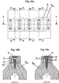
- Fig. 9a to 9f the composite (1) is arranged as an attached composite in a crankcase (7a) and shown in different views and sectional planes.
- the patch on the crankcase composite is shown in plan view, the sectional planes for the Fig. 9b to Fig. 9f are drawn.
- Fig. 9b shows the section plane AA
- Fig. 9c shows the section plane BB
- Fig. 9d shows the section plane CC
- Fig. 9e shows the section plane DD
- Fig. 9f shows the section plane EE.
- the sectional plane AA is shown, wherein the composite (1) mounted and via fastening means (13), here Switzerlanderschrauben, with the crankcase (7a) is connected.
- the tie bolts are threaded through the plate-shaped cylinder head support surface of the composite (1) into the crankcase.
- the coolant space or water space (11) is formed by the outer walls of the cylinders and the upper inner walls of the crankcase.
- the outer wall of the cylinder shown here has a horizontal circumferential bead (14).
- the bead is designed as a sealing bead (s. Fig. 10e ).
- the sealing bead is arranged on the cylinder in such a way that a seal is achieved between the coolant space or water space (11) and the lower crankcase.
- the composite (1) is provided in the present example for better illustration with three different coolant guides (6), although each of the variants can be implemented individually in a composite, wherein Fig. 9b a slot coolant guide, in Fig. 9c , two horizontally drilled coolant guides and in Fig. 9d a coolant guide are shown by freestanding cylinders. In Fig. 9f these coolant guides are shown as section EE from left to right.
- the coolant guides (6) are connected to the coolant space or water space (11), so that the coolant can be circulated around the cylinders.
- the composite (1) is arranged as an inserted composite in a crankcase (7a) and shown in different views and sectional planes.
- Fig. 10a the composite used on the crankcase is shown in plan view, wherein the sectional planes for the FIGS. 10b to 10f are drawn.
- Fig. 10b shows the section plane AA
- Fig. 10c shows the section plane BB
- Fig. 10d shows the section plane CC
- Fig. 10e shows the section plane DD
- Fig. 10f shows the section plane EE.
- the fastening means 13
- the fastening means here Buchankerschrauben
- the coolant space or water space (11) is formed by the outer walls of the cylinders and the upper inner walls of the crankcase.
- the outer wall of the cylinder shown here has a horizontal circumferential bead (14).
- the bead is designed as a sealing bead (s. Fig. 10e ).
- the sealing bead is arranged on the cylinder in such a way that a seal is achieved between the coolant space or water space (11) and the lower crankcase.
- the composite (1) is provided in the present example for better illustration with three different coolant guides (6), although each of the variants can be implemented individually in a composite, wherein Fig. 10b a slot coolant guide, in Fig.
- Fig. 10c two horizontally drilled coolant guides and in Fig. 10d a coolant guide are shown by freestanding cylinders.
- Fig. 10f these coolant guides are shown as section EE from left to right.
- the coolant guides (6) are connected to the coolant space or water space (11), so that the coolant can be circulated around the cylinders.
Landscapes
- Engineering & Computer Science (AREA)
- Mechanical Engineering (AREA)
- Chemical & Material Sciences (AREA)
- Combustion & Propulsion (AREA)
- General Engineering & Computer Science (AREA)
- Cylinder Crankcases Of Internal Combustion Engines (AREA)
Description
- Die vorliegende Erfindung betrifft eine Hubkolben-Verbrennungskraftmaschine und ein Verfahren zum Herstellen einer Hubkolben-Verbrennungskraftmaschine.
- Die Herstellung von Gussteilen ist gekennzeichnet durch eine zunehmende Integration von funktionalen Elementen des Gussbauteiles. Dies trifft insbesondere für Motorblöcke, insbesondere Zylinderkurbelgehäuse, zu. Derartige Kurbelgehäuse weisen komplizierte Innenräume auf, die im Finish-Prozess eine komplizierte Reinigung zur Entfernung der Sand- und oder Schlichterückstände aus dem Gießereiprozess erfordern. Insbesondere Zylinderkurbelgehäuse besitzen heute eine Vielzahl von integrierten gegossenen innen liegenden Funktionen, wie Wassermänteln, Passagen und Kanälen für Wasser oder Öl, die nach dem Gießen gereinigt werden müssen. Erschwerend kommt hinzu, dass für Motorenkomponenten die Anforderungen an die Bauteilsauberkeit bzw. die Restschmutzanforderungen in der letzten Zeit stark gestiegen sind.
- Zurzeit werden für die Reinigung Schleuderradstrahlmaschinen verwendet, die im Wesentlichen die Außenkonturen von Rückständen des Gießprozesses säubern. Innenkonturen werden in der Regel mit Druckstrahlgeräten gereinigt, wobei der Handprozess sowie typenbezogene Sondermaschinen aufgrund der komplexen Innenräume dominieren.
- Nachteilig ist derzeit, dass diese Reinigung aufwendig ist und durch die Vielzahl von integrierten gegossenen innen liegenden Funktionen, wie Wassermänteln, Passagen und Kanälen für Wasser oder Öl erschwert wird.
- Hubkolben-Verbrennungskraftmaschinen umfassend einen Zylinderkopf, ein Kurbelgehäuse und einen Verbund, wobei die Außenwandbereiche der Zylinder des Verbunds und die Wandbereiche der Aussparung zur Aufnahme des Verbunds des Kurbelgehäuses einen Kühlmittelraum ausbilden, sind beispielsweise aus der
US 3 168 081 A undUS 2006/037566 A1 bekannt. - Neben den gestiegenen Anforderungen an die Bauteilsauberkeit bzw. die Restschmutzanforderungen sind ebenfalls die Leistungsanforderungen, wie höhere Zünddrücke oder höhere Temperaturbelastungen, an die Motorblöcke gestiegen. Durch die geforderten steigenden Leistungen bei Verbrennungsmotoren, sind die vier klassischen Lastzonen eines Zylinderkurbelgehäuses, nämlich Lagerstuhl, Kopfverschraubung, Zylinderrohr und Zylindersteg, im Grenzbereich des aktuell technisch Machbaren angelangt.
- Es ist daher die Aufgabe der Erfindung die Reinigung der Motorblöcke nach dem Gießen zu erleichtern und es zu ermöglichen, aktuelle und zukünftige Restschmutzanforderungen einzuhalten sowie eine Lösung für die Herausforderungen aktueller und zukünftiger Hochleistungsmotoren, insbesondere für die Lastzonen Kopfplatte und Zylinderrohr, sowie Potential zur lokalen Verbesserung der Eigenschaften im Kurbelgehäuse in den weiteren Lastzonen Kopf- und Kurbelwellenlager-Verschraubung bereitzustellen.
- Die Aufgabe wird durch eine Hubkolben-Verbrennungskraftmaschine umfassend einen Zylinderkopf, ein Kurbelgehäuse und einen Verbund, wobei das Kurbelgehäuse eine Aussparung zur Aufnahme des Verbunds umfasst, wobei der Verbund wenigstens zwei Zylinder und eine diese verbindende plattenförmige Zylinderkopfauflagefläche umfasst, wobei der Verbund einstückig ausgebildet ist, wobei die plattenförmige Zylinderkopfauflagefläche für jeden Zylinder eine Ausnehmung aufweist und wobei der Verbund in ein Kurbelgehäuse einer Hubkolben-Verbrennungskraftmaschine einsetzbar oder auf ein Kurbelgehäuse einer Hubkolben-Verbrennungskraftmaschine aufsetzbar ist und wobei der Verbund zwischen dem Zylinderkopf und dem Kurbelgehäuse sowie in der Aussparung zur Aufnahme des Verbunds angeordnet ist und wobei die Außenwandbereiche der Zylinder des Verbunds und die Wandbereiche der Aussparung zur Aufnahme des Verbunds des Kurbelgehäuses einen Kühlmittelraum ausbilden, dadurch gelöst, dass wenigstens eine Kühlmittelführung zwischen den Zylindern des Verbunds angeordnet ist, wobei die Kühlmittelführung des Verbunds durch Durchbohrung des Zwischenbereichs zweier benachbarter Zylinder und/oder durch einen Kühlkanal-Kern im Zwischenbereich zweier Zylinder realisiert ist, und die plattenförmige Zylinderkopfauflagefläche des Verbunds - bis auf die Ausnehmungen für jeden Zylinder - durchtrittsfrei ausgebildet ist.
- Es ist zu der Erfindung gehörig, dass zwischen dem Zylinderkopf und dem Kurbelgehäuse ein Verbund angeordnet ist, wobei der Verbund einstückig ausgebildet ist und in ein Kurbelgehäuse einer Hubkolben-Verbrennungskraftmaschine eingesetzt ist oder mit der plattenförmigen Zylinderkopfauflagefläche auf das Kurbelgehäuse aufgesetzt und mit den Zylindern in die Aussparung des Kurbelgehäuses zur Aufnahme der Zylinder des Verbunds eingesetzt ist, und wobei die plattenförmige Zylinderkopfauflagefläche zur Auflage des Zylinderkopfes dient und für jeden Zylinder eine Ausnehmung aufweist.
- Hierbei ist für den Verbund der Hubkolben-Verbrennungskraftmaschine vorgesehen, dass eine Kühlmittelführung zwischen den Zylindern angeordnet ist, wobei die Kühlmittelführung durch Durchbohrung des Zwischenbereichs zweier benachbarter, möglicherweise verbundener Zylinder und/oder durch einen Kühlkanal-Kern im Zwischenbereich zweier benachbarter, möglicherweise verbundene, Zylinder realisiert ist.
- Es ist bei der erfindungsgemäßen Hubkolben-Verbrennungskraftmaschine vorgesehen, dass die Außenwandbereiche der Zylinder des Verbunds und die Wandbereiche der Aussparung zur Aufnahme des Verbunds des Kurbelgehäuses einen Kühlmittelraum bzw. Wasserraum ausbilden.
- Durch diese Ausgestaltung wird vorteilhaft erreicht, dass zur Ausbildung des Kühlmittelraums bzw. Wasserraumes keine Entformungsschrägen oder, im Falle von Druckgussfertigung, Losteile und oder Schieber mit größerem (1 bis >2°) Formkonus erforderlich sind. Parallel verlaufende oder gestufte Zylinderwände können ohne weiteres hergestellt werden. Ebenso können aufgrund der gewählten Formteilung Leit-/Kühl-/StützRippen etc. am Zylinderrohr vorgesehen werden und eine bedarfsangepasste Wandung des Zylinders ist möglich. Der Kühlmittelraum kann demnach frei gestaltet werden.
- Aufgrund der Kühlmittelraumbildung durch die separat hergestellten Bauteile, Verbund und offenes Kurbelgehäuse, kann eine sehr dünne bzw. schmale Wassermantel-Geometrie hergestellt werden. Die Geometrie kann deutlich filigraner dargestellt bzw. ausgebildet werden als dies heute technisch, mittels Kernen und Schiebern, erreichbar ist.
- Es ist vorgesehen, dass die Wassermantel-Geometrie eine Stärke von weniger als 5 mm, vorzugsweise weniger als 3,5 mm, aufweist.
- Durch die dünne bzw. schmale Wassermantel-Geometrie wird vorteilhaft erreicht, dass weniger Kühlmittel als bei vorbekanntem Stand der Technik benötigt wird. Dementsprechend ist die benötigte Pumpleistung geringer als bei bekannten Pumpen und die Pumpe kann dadurch kleiner ausgestaltet werden als die bisher verwendeten Pumpen. Dies spart Gewicht, damit Kosten, und Raum.
- Es ist weiterhin vorteilhaft bei der erfindungsgemäßen Hubkolben-Verbrennungskraftmaschine vorgesehen, dass die die wenigstens zwei Zylinder verbindende plattenförmige Zylinderkopfauflagefläche auf das Kurbelgehäuse aufgesetzt ist oder in die Aussparung zur Aufnahme des Verbunds eingesetzt ist. "Aufgesetzt" bedeutet in diesem Zusammenhang, dass die Zylinderkopfauflagefläche die Ausnehmung des Kurbelgehäuses abdeckt bzw. überlappt. "Eingesetzt" bedeutet in diesem Zusammenhang, dass die Zylinderkopfauflagefläche formschlüssig in die Ausnehmung des Kurbelgehäuses einbringbar ist. Bei letzterer Ausgestaltung kann die Ausnehmung des Kurbelgehäuses wenigstens einen nach innen gerichteten zumindest teilweise umlaufenden Vorsprung bzw. Sitz aufweisen, so dass der Außenbereich der Zylinderkopfauflagefläche auf dem Vorsprung bzw. Sitz aufliegen kann.
- Es ist vorgesehen, dass die Aussparung des Kurbelgehäuses zur Aufnahme des Verbunds in ihrer Geometrie derart ausgestaltet ist, dass der Verbund zumindest teilweise, zumindest die Zylinder, in dem Kurbelgehäuse angeordnet werden kann.
- Es kann vorteilhaft vorgesehen sein, dass die Aussparung zur Aufnahme des Verbunds in ihrer Innengeometrie der Außengeometrie der wenigstens zwei Zylinder entspricht. Die Zylinder können demnach passgenau in das Kurbelgehäuse eingesetzt werden. Zusätzlich oder alternativ kann vorgesehen sein, dass die Aussparung zur Aufnahme des Verbunds in ihrer oberen Innengeometrie der Außengeometrie der plattenförmigen Zylinderkopfauflagefläche entspricht, wobei vorgesehen sein kann, dass die plattenförmige Zylinderkopfauflagefläche durch einen umlaufenden Vorsprung in der Aussparung gehalten wird.
- Durch eine separate Herstellung des Verbunds und des "offenen" Kurbelgehäuses ergeben sich weitere Vorteile für die Herstellung des Kurbelgehäuses. Beispielsweise wird eine deutlich vereinfachte Zugänglichkeit für bauteilinnere Speisungsmaßnahmen erreicht, wodurch das Gefüge im Lagerstuhlbereich durch den Einsatz von Kühlelementen hinsichtlich der daraus resultierenden mechanischen Eigenschaften positiv beeinflusst werden kann. Weiterhin kommt vorteilhaft hinzu, dass die Reinigung des "offenen" Kurbelgehäuses vereinfacht wird, wodurch die Restschmutzanforderungen deutlich einfacher eingehalten werden können.
- Vorteilhaft kommt hinzu, dass das erfindungsgemäße Kurbelgehäuse in kostengünstigen und einfach zu beherrschenden Legierungen anforderungsgerecht hergestellt werden kann. Im Falle, dass Laufflächenbeschichtungen verwendet werden, können beispielsweise die Maskierung (Abdeckung) zur Vermeidung von Overspray und zusätzliche Reinigungsschritte nach dem Sprayen im Kurbelraumbereich entfallen.
- Durch die einstückige Ausbildung des mehrzylindrigen Verbunds wird vorteilhaft erreicht, dass der Verbund als separates Bauteil hergestellt werden kann. Für die Herstellung können verschiedene Verfahren angewendet werden. Vorzugsweise wird das Bauteil gegossen. Es ist jedoch ebenso im Rahmen der Erfindung vorgesehen, dass das Herstellen des Verbunds durch einen Tiefziehprozess oder das Schmieden des Verbundes unter Verwendung von beispielsweise Aluminium-Kupfer-Knetlegierungen erreicht wird.
- Es ist für die plattenförmige Zylinderkopfauflagefläche des mehrzylindrigen Verbunds vorgesehen, dass diese in ihrer Geometrie frei gestaltbar ist. Beispielsweise kann die Dicke der plattenförmigen Zylinderkopfauflagefläche entsprechend der anfallenden Belastungen hergestellt werden. Ebenso ist hierbei vorstellbar, dass die plattenförmige Zylinderkopfauflagefläche größere Dicken in belasteten Bereichen und minimale Dicken in nicht belasteten Bereichen aufweist. Ebenfalls ist vorgesehen, dass die Geometrie der plattenförmigen Zylinderkopfauflagefläche frei gestaltbar ist, beispielsweise derart, dass die plattenförmige Zylinderkopfauflagefläche an die Geometrie des Kurbelgehäuses und des Zylinderkopfes angepasst ist.
- Da der Verbund keinen integrierten Kühlmittelraum umfassen muss, sind die äußeren Zylinderwände entsprechend den Anforderungen frei gestaltbar. Beispielsweise kann eine kraftfluss- und/oder anforderungsoptimierte Stützstruktur, wie beispielsweise Rippenverstärkungen und Dergleichen oder Kühlrippen, an den äußeren Zylinderwänden realisiert werden. Hierbei ist vorteilhaft vorgesehen, dass die Stützstruktur (Rippen) derart an den Zylinderwänden angeordnet ist, dass eine Strömungsoptimierung erreicht wird. Die Stützstruktur (Rippen) wird bereits bei der Herstellung der Zylinder mithergestellt.
- Es ist erfindungsgemäß vorgesehen, dass wenigstens eine Kühlmittelführung bzw. Stegkühlung zwischen den Zylindern angeordnet ist.
- Da der Verbund mit seinen Zylindergeometrien und der plattenförmigen Zylinderkopfauflagefläche nicht zusammen mit dem Zylinderkurbelgehäuse hergestellt wird, sondern separat hergestellt und in diesen einsetzbar oder auf diesen aufsetzbar ist (die plattenförmige Zylinderkopfauflagefläche liegt auf dem Kurbelgehäuse auf, wobei die Zylinder in das Kurbelgehäuse hineinragen), kann die Kühlmittelführung sehr universell, individuell und ohne Einschränkungen bzgl. Position, z.B. auch unmittelbar unter und parallel zur Zylinderkopfauflagefläche, hergestellt werden.
- Zwischen den Zylindern bedeutet, dass zwischen wenigstens zwei benachbarten Zylindern wenigstens eine Aussparung bzw. Ausnehmung vorhanden ist, so dass Kühlmittel von einer Seite des Verbunds durch die Aussparung bzw. Ausnehmung auf die gegenüberliegende Seite des Verbunds gelangen kann. Dementsprechend werden die Zylinder auch in dem Bereich zwischen den Zylindern gekühlt. Hierbei kann vorgesehen sein, dass eine Kühlmittelführung zwischen allen benachbarten Zylindern angeordnet ist. Ebenso kann vorgesehen sein, dass die Kühlmittelführung nur zwischen manchen Zylindern, z.B. in jedem zweiten Bereich zwischen zwei benachbarten Zylindern, angeordnet ist.
- Ebenso ist es ein Vorteil der Erfindung, dass die Zylinderrohrform und Zylinderrohrwandung entsprechend den Anforderungen frei gestaltbar sind. Die Ausgestaltung der Zylinderrohrform ist wichtig, um der Verformung durch die Verschraubung entgegenzuwirken. Beispielsweise kann die Zylinderrohrwandung konvex (nach außen gewölbt), konkav (nach innen gewölbt), sinusförmig, stufenförmig oder als eine Mischung der vorgenannten Möglichkeiten ausgestaltet sein oder mit Stützstrukturen, Kühlrippen oder Dergleichen versehen sein. Die gestaltbare Zylinderrohrform und Zylinderrohrwandung haben den Vorteil, dass die Zylinderwandstärke im Bereich der hohen Zünddrücke erhöht werden kann. Weiterhin kann durch die ausgewählte Form (konvex, konkav,...) eine Strömungsoptimierung erreicht werden. Beispielsweise wird durch eine angepasste Ausgestaltung eine höhere Strömungsgeschwindigkeit ermöglicht.
- Dadurch, dass der Verbund separat hergestellt wird und erst nach dem Herstellen, beispielsweise durch Gießen, in das separat hergestellte Kurbelgehäuse eingesetzt oder auf es aufgesetzt bzw. in diesem montiert wird, kann das Kurbelgehäuse als "offenes" Kurbelgehäuse hergestellt werden und die Zylinder können vor dem Einsetzen leicht bearbeitet werden, was eine große Freiheit in der Gestaltung der Zylinderaußenwand ermöglicht.
- Dies ermöglicht eine verbesserte Zugänglichkeit für kurbelgehäuseinterne Speisungsmaßnahmen, beispielsweise bei Nichteisen-Legierungen oder Eisenbasiswerkstoffen, sowie signifikant verbesserte Reinigungsmöglichkeiten des Verbunds und des "offenen" Kurbelgehäuses mit den bekannten Reinigungsverfahren. Die Erfindung ermöglicht ebenfalls die aktuell sehr häufig nachgefragte, komplett getrennte Kühlmittelführung von Zylinderkopf und Kurbelgehäuse, da keine Öffnungen zur Lagerung des sonst üblichen Wassermantels oder Losteilschieber erforderlich sind. So ist eine geschlossene Kopffläche möglich. Die plattenförmige Zylinderkopfauflagefläche kann aber auch, je nach Bedarf, örtlich geöffnet werden um eine Verbindung zwischen dem Kühlmittelraum bzw. Wasserraum des Kurbelgehäuses zum Kühlmittelraum bzw. Wasserraum des Kopfes zu ermöglichen.
- Da der Verbund in ein "offenes" Kurbelgehäuse einer Hubkolben-Verbrennungskraftmaschine eingesetzt wird, ist vorteilhaft vorgesehen, dass die plattenförmige Zylinderkopfauflagefläche in ihren Dimensionen derart ausgestaltet ist, dass sie weitestgehend formschlüssig in das offene Kurbelgehäuse eingebracht wird. Durch diese Ausgestaltung wird ein einfacheres Abdichten - Kurbelgehäuse und Verbund - erreicht.
- Eine Ausgestaltung der Erfindung sieht vor, dass die Außenwand der Zylinder wenigstens einen horizontal zumindest teilweise umlaufenden Wulst aufweisen. Der Wulst ist vorzugsweise als Dichtwulst ausgebildet. Der Dichtwulst ist vorzugsweise derart an dem Zylinder angeordnet, dass eine Dichtung zwischen einem Kühlmittelraum bzw. Wasserraum (gebildet durch die Außenwände der Zylinder und den oberen Innenwänden des Kurbelgehäuses) und dem unteren Kurbelgehäuse erreicht wird.
- Der Verbund bietet somit durch die beschriebenen Vorteile die Möglichkeit zur Verbesserung von Verbrennungsmotoren für aktuelle und zukünftige höhere Zünddrücke und höhere Temperaturbelastungen im Bereich Kopfplatte und Zylindersteg, sowie Zylinderrohr.
- Insbesondere können durch den erfindungsgemäßen Verbund die Herausforderungen bzgl. Temperaturwechselbeständigkeit, Temperaturbelastung des Zylinderstegs ("Zwickel"), Tribologie, Plattensteifigkeit und -festigkeit, Zylinderverzug, Beschichtungsfähigkeit der Laufbahnen (bei Al-Leg.) einfacher gelöst werden.
- Es ist weiterhin erfindungsgemäß vorgesehen, dass die plattenförmige Zylinderkopfauflagefläche des Verbunds- bis auf die Ausnehmungen für jeden Zylinder - durchtrittsfrei ausgebildet ist.
- Durch diese Ausgestaltung wird erreicht, dass die Steifigkeit und Struktur der Zylinderkopfauflagefläche nicht durch Durchtritte geschwächt wird. Dies ermöglicht auch ein vereinfachtes Abdichten zwischen dem Zylinderkopf und dem Zylinderkurbelgehäuse, da keine/kaum Versickungen, Stopper, etc. bei Einsatz einer Kopfdichtung an der Zylinderkopfauflagefläche angeordnet sind. Vorteilhaft wird durch diese Ausgestaltung weiterhin erreicht, dass die Verbrennungskraftmaschine höheren Drücken ausgesetzt werden kann. Ebenso kann die Tendenz zur Rissbildung der Zylinderkopfauflagefläche, die von Durchtritten als Anfangsort begünstigt wird, vermindert bis verhindert werden.
- Für den Verbund ist weiterhin vorteilhaft vorgesehen, dass der Verbund aus Gusseisen mit Lamellengraphit (GJL), Gusseisen mit Vermiculargraphit (GJV), Gusseisen mit Kugelgraphit (GJS) und/oder Stahl und/oder einer Kombination der vorgenannten Werkstoffe hergestellt ist.
- Durch den separat hergestellten Verbund aus einem dieser oder einer Kombination dieser Eisenbasiswerkstoffe kann die Herstellung der Brennkraftmaschine insgesamt, durch beispielsweise Gießen, vereinfacht werden. Ebenso wird erreicht, dass durch die separate Herstellung eine anforderungsoptimierte Steuerung der Feinkörnigkeit und der Porenfreiheit des Zylinderrohrgefüges ermöglicht wird, ohne dass das Kurbelgehäuse beeinflusst wird. Beispielsweise kann eine Abschreckschicht oberflächennah der Lauffläche realisiert werden. Ebenso oder zusätzlich kann eine durchgehend abgeschreckte Zylinderwandung realisiert werden. Durch diese separate Behandlung des Verbunds wird eine verbesserte Wärmeleitung und -Übergang/Abführung in den Kühlkreislauf sowie Einstellbarkeit der mechanischen Eigenschaften (Zugfestigkeit R m, Dehngrenze R p0,2 und Bruchdehnung A) ermöglicht. Es ist ebenfalls vorteilhaft, dass durch die Verwendung von Eisenbasiswerkstoffen ein nachträgliches Fügen der Laufbuchsen sowie eine separate Laufbahnbeschichtung entfallen können. Insbesondere durch die Verwendung des Werkstoffs Gusseisen mit Kugelgraphit kann sowohl eine höhere Festigkeit als auch eine höhere Dehnung erreicht werden.
- Für eine alternative Ausgestaltung des erfindungsgemäßen Verbundes ist vorgesehen, dass der Verbund aus Nichteisenwerkstoffen, insbesondere Aluminiumlegierungen, wie Aluminium-Magnesium-Legierungen (AlMgxx), Aluminium-Silizium-Legierungen (AlSixx) mit Kupfer (Cu) und/oder Magnesium (Mg) und/oder Aluminiumknetlegierungen, hergestellt ist.
- Durch die Verwendung von Nichteisenwerkstoffen für die Herstellung des Verbunds kann dieser ohne Speisungsmaßnahmen hergestellt werden. Insbesondere ist vorteilhaft, dass ein nachträglicher Liner-Umguss sowie das nachträgliche Fügen des Liners entfallen. Vorteilhaft ist insbesondere, dass nur der Verbund aus Nichteisenwerkstoffen, insbesondere Aluminiumlegierungen, hergestellt wird, und nicht das komplette Zylinderkurbelgehäuse (Verbund und "offenes" Kurbelgehäuse).
- Bei Nichteisenwerkstoffen, insbesondere auf Aluminium-Basis, wird ermöglicht, dass durch den Einsatz von Kühlelementen im Zylinderrohr (Kokillen aus Stahl, GJL, Ms,...) eine beschichtungsfähige Lauffläche hergestellt werden kann, ohne dass das Kurbelgehäuse beeinflusst wird.
- Es ist ebenfalls für den Verbund vorstellbar, dass eine Kühlnut auf der dem Zylinderkopf zugewandten Seite der Zylinderkopfauflagefläche angeordnet ist, die für eine Reduzierung der Temperaturen im Stegbereich dient. Es ist weiterhin vorgesehen, dass die Kühlnut seitens des Zylinderkopfes mit Kühlmittel versorgt wird.
- Weiterhin wird eine Hubkolben-Verbrennungskraftmaschine umfassend einen Zylinderkopf, ein Kurbelgehäuse sowie einen einstückig aus einem Zylinder und einer Zylinderkopfauflagefläche ausgebildeteten Verbund, wobei die plattenförmige Zylinderkopfauflagefläche eine Ausnehmung für den einen Zylinder aufweist und wobei das Kurbelgehäuse eine Aussparung zur Aufnahme des einen einstückig aus einem Zylinder und einer Zylinderkopfauflagefläche ausgebildeteten Verbunds aufweist, gezeigt, bei der ein Bereich der Zylinderaußenwand des Verbunds und die Aussparung des Kurbelgehäuses zur Aufnahme des Verbunds einen Kühlmittelraum bzw. Wasserraum bilden.
- Der hier beschriebene Verbund besteht aus genau einem Zylinder und einer Zylinderkopfauflagefläche. Die Zylinderkopfauflagefläche kann gemäß dem mehrzylindrigen Verbund ausgestaltet sein. Ebenso ist vorgesehen, dass der einzylindrige Verbund aus denselben Materialien wie der mehrzylindrige Verbund hergestellt sein kann.
- Die Aufgabe wird ebenfalls durch ein Verfahren zum Herstellen der Hubkolben-Verbrennungskraftmaschine gelöst.
- Das Verfahren umfasst folgende Schritte:
- Separates Herstellen des Kurbelgehäuses, des Verbunds und des Zylinderkopfes,
- Einsetzen des Verbunds in das Kurbelgehäuse,
- Anordnen des Zylinderkopfes auf der plattenförmigen Zylinderkopfauflagefläche des Verbunds,
- Verbinden des Kurbelgehäuses, des Verbunds und des Zylinderkopfes.
- Es ist zu der Erfindung gehörig, dass die Schritte
- Einsetzen des Verbunds in das Kurbelgehäuse,
- Anordnen des Zylinderkopfes auf der plattenförmigen Zylinderkopfauflagefläche des Verbunds,
- Es ist erfindungsgemäß zu dem Verfahren gehörig, dass das Verbinden des Kurbelgehäuses, des Verbunds und des Zylinderkopfes durch gängige Verfahren wie Schrauben, Kleben, Klemmen, Dichten oder Dergleichen erreicht wird. Durch die einstückige Ausbildung des Verbunds wird vorteilhaft erreicht, dass die Zylinder beim Verbinden kaum oder gar nicht verzogen werden, da der Kraftfluss beim Verbinden (beispielsweise durch Anziehen von Zylinderkopfschrauben) von den Zylinderohren entkoppelt ist. Durch die Ausgestaltung kann weiterhin eine schlankere Zylinderwandung realisiert werden, was zu einer Gewichts- und damit Kostenreduzierung führt.
- Nachfolgend wird die Erfindung anhand von Zeichnungen näher, jedoch nicht darauf beschränkt, erläutert. Es zeigen
- Fig. 1
- den Verbund aus vier Zylindern und einer diese verbindenden plattenförmigen Zylinderkopfauflagefläche in perspektivischer Ansicht,
- Fig. 2
- den Verbund aus vier Zylindern und einer diese verbindenden plattenförmigen Zylinderkopfauflagefläche in, im Vergleich zu
Fig. 1 umgedrehter, perspektivischer Ansicht, - Fig. 3a
- den Verbund aus vier Zylindern und einer diese verbindenden plattenförmigen Zylinderkopfauflagefläche, wobei die Kühlmittelführung durch Durchbohrung des Zwischenbereich zweier benachbarter in Längsrichtung verbundener Zylinder realisiert ist, in vertikaler Schnittansicht,
- Fig. 3b
- den Verbund aus vier Zylindern und einer diese verbindenden plattenförmigen Zylinderkopfauflagefläche, wobei die Kühlmittelführung durch einen Kühlkanal-Kern im Zwischenbereich zweier benachbarter in Längsrichtung verbundener Zylinder realisiert ist, in vertikaler Schnittansicht,
- Fig. 3c
- den Verbund aus vier Zylindern und einer diese verbindenden plattenförmigen Zylinderkopfauflagefläche, wobei die Kühlmittelführung durch freistehende Zylinder realisiert ist, in vertikaler Schnittansicht,
- Fig. 3d
- den Verbund aus vier Zylindern und einer diese verbindenden plattenförmigen Zylinderkopfauflagefläche, wobei eine Kühlnut auf der Zylinderkopfauflagefläche angeordnet ist, in vertikaler Schnittansicht,
- Fig. 4
- eine erfindungsgemäße Hubkolben-Verbrennungskraftmaschine umfassend einen Zylinderkopf und ein Kurbelgehäuse, wobei zwischen dem Zylinderkopf und dem Kurbelgehäuse ein Verbund aus vier Zylindern und einer diese vier Zylinder verbindenden plattenförmigen Zylinderkopfauflagefläche angeordnet ist, in Explosionsdarstellung,
- Fig. 5
- einen Verbund (VR-Inline Variante) und ein entsprechendes offenes Kurbelgehäuse (VR-Inline Kurbelgehäuse), wobei der Verbund sechs Zylinder und eine diese Zylinder verbindenden plattenförmige Zylinderkopfauflagefläche umfasst, wobei die Zylinder in Längsrichtung versetzt zueinander angeordnet sind, in Explosionsdarstellung,
- Fig. 6
- eine erfindungsgemäße Hubkolben-Verbrennungskraftmaschine umfassend einen Zylinderkopf und ein Kurbelgehäuse, wobei zwischen dem Zylinderkopf und dem Kurbelgehäuse ein Verbund aus vier Zylindern und einer diese vier Zylinder verbindenden plattenförmigen Zylinderkopfauflagefläche angeordnet ist, wobei die Zylinderkopfauflagefläche im zusammengebauten Zustand auf dem Kurbelgehäuse aufliegt, in Explosionsdarstellung,
- Fig. 7
- eine erfindungsgemäße Hubkolben-Verbrennungskraftmaschine umfassend einen Zylinderkopf und ein Kurbelgehäuse, wobei zwischen dem Zylinderkopf und dem Kurbelgehäuse ein Verbund aus vier Zylindern und einer diese vier Zylinder verbindenden plattenförmigen Zylinderkopfauflagefläche angeordnet ist, wobei die Zylinderkopfauflagefläche im zusammengebauten Zustand in der Aussparung des Kurbelgehäuses in etwa formschlüssig eingebracht ist, in Explosionsdarstellung,
- Fig. 8
- den Verbund aus vier Zylindern und einer diese verbindenden plattenförmigen Zylinderkopfauflagefläche, wobei vier verschieden angeordnete Kühlnuten an den Zylindern angeordnet sind, in perspektivischer Ansicht,
- Fig. 9a-9f
- verschiedene Schnittdarstellungen eines in einem offenen Kurbelgehäuse angeordneten Verbundes,
- Fig. 10a-10f
- verschiedene Schnittdarstellungen eines in einem offenen Kurbelgehäuse angeordneten Verbundes.
- In
Fig. 1 ist ein Verbund (1) aus vier Zylindern (2a, 2b, 2c, 2d) und einer diese Zylinder verbindenden plattenförmigen Zylinderkopfauflagefläche (5), wobei der Verbund (1) aus wenigstens zwei Zylindern (2a, 2b, 2c, 2d) und der diese verbindenden plattenförmigen Zylinderkopfauflagefläche (5) einstückig ausgebildet ist, in perspektivischer Ansicht dargestellt. Wie gezeigt, weist die plattenförmige Zylinderkopfauflagefläche (5) für jeden Zylinder (2a; 2b; 2c; 2d) eine Ausnehmung (3a; 3b; 3c; 3d) auf. Es ist vorgesehen, dass der Verbund (1) in ein ("offenes") Kurbelgehäuse (7a; 7b) einer Hubkolben-Verbrennungskraftmaschine einsetzbar oder auf dieses aufsetzbar ist. Weiterhin ist gezeigt, dass die plattenförmige Zylinderkopfauflagefläche (5) - bis auf die Ausnehmungen (3a; 3b; 3c; 3d) für jeden Zylinder (2a; 2b; 2c; 2d) - durchtrittsfrei ausgebildet ist. -
Fig. 2 zeigt den Verbund (1) aus vier Zylindern und einer diese verbindenden plattenförmigen Zylinderkopfauflagefläche (5) in, im Vergleich zuFig. 1 umgedrehter, perspektivischer Ansicht. Da der Verbund (1) separat hergestellt ist, wird ermöglicht, dass durch den Einsatz von Kühlelementen im Zylinderrohr (Kokillen aus Stahl, GJL, Ms,...) eine beschichtungsfähige Lauffläche (4a; 4b; 4c; 4d) hergestellt werden kann, ohne dass das Kurbelgehäuse beeinflusst wird. Ebenso wird erreicht, dass durch die separate Herstellung eine anforderungsoptimierte Steuerung der Feinkörnigkeit und der Porenfreiheit des Zylinderrohrgefüges ermöglicht wird, ohne dass das Kurbelgehäuse beeinflusst wird. Beispielsweise kann eine Abschreckschicht oberflächennah der Lauffläche realisiert werden. Ebenso oder zusätzlich kann eine durchgehend abgeschreckte Zylinderwandung realisiert werden. - In den
Fig. 3a bis 3c ist der Verbund (1) aus vier Zylindern (2a, 2b, 2c, 2d) und einer diese verbindenden plattenförmigen Zylinderkopfauflagefläche in vertikalen Schnittansichten gezeigt. InFig. 3a ist dargestellt, dass die Kühlmittelführung (6) durch Durchbohrung des Zwischenbereichs zweier benachbarter in Längsrichtung verbundener Zylinder (2a, 2b, 2c, 2d) realisiert werden kann. InFig. 3b ist dargestellt, dass die Kühlmittelführung (6) durch einen Kühlkanal-Kern im Zwischenbereich zweier benachbarter in Längsrichtung verbundener Zylinder (2a, 2b, 2c, 2d) realisiert werden kann. InFig. 3c ist dargestellt, dass die Kühlmittelführung (6) durch freistehende Zylinder (2a; 2b; 2c; 2d) realisiert werden kann. - In den
Fig. 3d ist der Verbund (1) aus vier Zylindern (2a, 2b, 2c, 2d) und einer diese verbindenden plattenförmigen Zylinderkopfauflagefläche in vertikalen Schnittansichten gezeigt. InFig, 3d ist dargestellt, dass eine Kühlnut (6a) in der plattenförmigen Zylinderkopfauflagefläche angeordnet ist. Die Geometrie, Form und Lage der Kühlnut (6a) sind nicht beschränkt auf die dargestellte spaltähnliche Ausführungsform, sondern kann entsprechend dem Bedarf auf der Zylinderkopfauflagefläche angeordnet sein. -
Fig. 4 zeigt eine erfindungsgemäße Hubkolben-Verbrennungskraftmaschine, umfassend einen Zylinderkopf (8) und ein erfindungsgemäßes Kurbelgehäuse (7a), wobei zwischen dem Zylinderkopf (8) und dem Kurbelgehäuse (7a) ein Verbund (1) aus vier Zylindern und einer diese vier Zylinder verbindenden plattenförmigen Zylinderkopfauflagefläche angeordnet ist, in Explosionsdarstellung. - Wie in
Fig. 4 dargestellt, wird keine separate Zylinderkopfdichtung benötigt, wodurch die Kraftübertragung direkt und flächig erfolgen kann und nicht beschränkt ist auf eine Zylinderkopfdichtungskontur. Dies ist insbesondere im hochbelasteten Bereich (Kompressionsbereich) vorteilhaft. - In
Fig. 5 ist ein Verbund (1; VR6-Inline Variante) und ein entsprechendes offenes Kurbelgehäuse (7c; VR6-Inline Kurbelgehäuse) in Explosionsdarstellung dargestellt. Der Verbund (1) umfasst sechs Zylinder (2, 2b. 2c, 2d, 2e, 2f) und eine diese Zylinder verbindende plattenförmige Zylinderkopfauflagefläche (5). Der Verbund (1) ist derart ausgestaltet, dass er in das Kurbelgehäuse (7c) eingesetzt wird (die plattenförmige Zylinderkopfauflagefläche kann auf einem Sitz in dem Kurbelgehäuse in etwa formschlüssig eingebracht werden; die Zylinder sind in dem Kurbelgehäuse geführt). Die Zylinder sind in Längsrichtung versetzt zueinander angeordnet und haben jeweils eine Schränkung (zur Längsachse hin) von ca. 15 %. Die Zylinder (2, 2b. 2c, 2d, 2e, 2f) können frei geführt in dem Kurbelgehäuse (7c) angeordnet werden. Die Innenkontur der Aussparung des Kurbelgehäuses (zur Aufnahme des Verbunds) kann im Wesentlichen glatt oder, wie hier dargestellt, eine Kontur aufweisen. Auf der plattenförmigen Zylinderkopfauflagefläche (5) sind Kühlnuten (6a) gezeigt. Die Kühlnuten (6a) sind zumindest teilweise radial umlaufend um die Ausnehmungen für die Zylinder angeordnet, wobei die Form, die Größe, die Anzahl, die Tiefe und die Lage frei gestaltbar sind. -
Fig. 6 zeigt eine erfindungsgemäße Hubkolben-Verbrennungskraftmaschine in Explosionsdarstellung. Die Hubkolben-Verbrennungskraftmaschine umfasst einen Zylinderkopf (8) und ein Kurbelgehäuse (7a), wobei zwischen dem Zylinderkopf (8) und dem Kurbelgehäuse (7a) ein Verbund (1) aus vier Zylindern und einer diese vier Zylinder verbindende plattenförmige Zylinderkopfauflagefläche angeordnet ist. Bei der erfindungsgemäßen Hubkolben-Verbrennungskraftmaschine ist der Verbund (1) auf das Kurbelgehäuse (7a) aufgesetzt (die plattenförmige Zylinderkopfauflagefläche liegt auf dem Kurbelgehäuse auf, die Zylinder sind in dem Kurbelgehäuse geführt). Auf der plattenförmigen Zylinderkopfauflagefläche sind drei Kühlnuten (6a) gezeigt. Die Kühlnuten (6a) sind zwischen den Ausnehmungen für die Zylinder angeordnet. -
Fig. 7 zeigt eine erfindungsgemäße Hubkolben-Verbrennungskraftmaschine in Explosionsdarstellung. Die Hubkolben-Verbrennungskraftmaschine umfasst einen Zylinderkopf (8) und ein Kurbelgehäuse (7a), wobei zwischen dem Zylinderkopf (8) und dem Kurbelgehäuse (7a) ein Verbund (1) aus vier Zylindern und einer diese vier Zylinder verbindende plattenförmige Zylinderkopfauflagefläche angeordnet ist. Bei der erfindungsgemäßen Hubkolben-Verbrennungskraftmaschine ist der Verbund (1) formschlüssig in das Kurbelgehäuse (7a) eingesetzt (die plattenförmige Zylinderkopfauflagefläche liegt auf einem Absatz in dem Kurbelgehäuse auf, so dass die Zylinderkopfauflagefläche und die Oberseite des Kurbelgehäuses im montierten Zustand plan sind; die Zylinder sind in dem Kurbelgehäuse geführt). - In
Fig. 8 ist ein Verbund (1) aus vier Zylindern und einer diese Zylinder verbindenden plattenförmigen Zylinderkopfauflagefläche, wobei der Verbund (1) einstückig ausgebildet ist, in perspektivischer Ansicht dargestellt. Die Außenwände der Zylinder weisen einen horizontal umlaufenden Wulst (14) auf. Der Wulst (14) ist vorzugsweise als Dichtwulst ausgebildet und dient im Betriebszustand (zusammenmonierter Zustand der Hubkolben-Verbrennungskraftmaschine) als Dichtung zwischen dem Kühlmittelraum bzw. Wasserraum (gebildet durch die Außenwände der Zylinder und den oberen Innenwänden des Kurbelgehäuses) und dem unteren Kurbelgehäuse. Die Form, die Lage und die Größe des Wulstes (14) sind frei gestaltbar. Ebenfalls ist inFig. 8 gezeigt, dass an den äußeren Zylinderwänden (vier gezeigte) Stützstrukturen (6b), hier Rippenverstärkungen, die auch Kühlrippen sein können, realisiert sind. Hierdurch wird unter anderem eine Strömungsoptimierung erreicht. Die Stützstrukturen (Rippen) können in beliebiger Weise (wie dargestellt z.B. längs, quer oder schräg) an den Außenwänden der Zylinder angeordnet sein. - In den
Fig. 9a bis 9f ist der Verbund (1) als aufgesetzter Verbund in einem Kurbelgehäuse (7a) angeordnet und in verschiedenen Ansichten und Schnittebenen dargestellt. InFig. 9a ist der auf das Kurbelgehäuse aufgesetzte Verbund in Draufsicht dargestellt, wobei die Schnittebenen für dieFig. 9b bis Fig. 9f eingezeichnet sind.Fig. 9b zeigt die Schnittebene A-A,Fig. 9c zeigt die Schnittebene B-B,Fig. 9d zeigt die Schnittebene C-C,Fig. 9e zeigt die Schnittebene D-D undFig. 9f zeigt die Schnittebene E-E. InFig. 9b ist die Schnittebene A-A dargestellt, wobei der Verbund (1) aufgesetzt und über Befestigungsmittel (13), hier Zugankerschrauben, mit dem Kurbelgehäuse (7a) verbunden ist. Die Zugankerschrauben sind durch die plattenförmige Zylinderkopfauflagefläche des Verbunds (1) in das Kurbelgehäuse geschraubt. Wie dargestellt, ist der Kühlmittelraum bzw. Wasserraum (11) durch die Außenwände der Zylinder und den oberen Innenwänden des Kurbelgehäuses gebildet. In denFig. 10b bis 10f ist weiterhin dargestellt, dass die Außenwand des hier gezeigten Zylinders einen horizontal umlaufenden Wulst (14) aufweist. Der Wulst ist als Dichtwulst ausgebildet (s.Fig. 10e ). Der Dichtwulst ist derart an dem Zylinder angeordnet, dass eine Dichtung zwischen dem Kühlmittelraum bzw. Wasserraum (11) und dem unteren Kurbelgehäuse erreicht wird. Der Verbund (1) ist im vorliegenden Beispiel zur besseren Veranschaulichung mit drei verschiedenen Kühlmittelführungen (6) versehen, obwohl jede der Varianten einzeln in einem Verbund umsetzbar ist, wobei inFig. 9b eine Schlitzkühlmittelführung, inFig. 9c , zwei horizontal gebohrte Kühlmittelführungen und inFig. 9d eine Kühlmittelführung durch freistehende Zylinder gezeigt sind. InFig. 9f sind diese Kühlmittelführungen als Schnitt E-E von links nach rechts dargestellt. - Die Kühlmittelführungen (6) sind mit dem Kühlmittelraum bzw. Wasserraum (11) verbunden, so dass das Kühlmittel um die Zylinder herum geführt bzw. zirkuliert werden kann.
- In den
Fig. 10a bis 10f ist der Verbund (1) als eingesetzter Verbund in einem Kurbelgehäuse (7a) angeordnet und in verschiedenen Ansichten und Schnittebenen dargestellt. InFig. 10a ist der auf das Kurbelgehäuse eingesetzte Verbund in Draufsicht dargestellt, wobei die Schnittebenen für dieFig. 10b bis Fig. 10f eingezeichnet sind.Fig. 10b zeigt die Schnittebene A-A,Fig. 10c zeigt die Schnittebene B-B,Fig. 10d zeigt die Schnittebene C-C,Fig. 10e zeigt die Schnittebene D-D undFig. 10f zeigt die Schnittebene E-E. In denFig. 10a bis 10e ist gezeigt, dass die Befestigungsmittel (13), hier Zugankerschrauben, in das Kurbelgehäuse (7a) eingreifen, jedoch nicht in den Verbund (1) geführt werden. Wie dargestellt, ist der Kühlmittelraum bzw. Wasserraum (11) durch die Außenwände der Zylinder und den oberen Innenwänden des Kurbelgehäuses gebildet. In denFig. 10b bis 10f ist weiterhin dargestellt, dass die Außenwand des hier gezeigten Zylinders einen horizontal umlaufenden Wulst (14) aufweist. Der Wulst ist als Dichtwulst ausgebildet (s.Fig. 10e ). Der Dichtwulst ist derart an dem Zylinder angeordnet, dass eine Dichtung zwischen dem Kühlmittelraum bzw. Wasserraum (11) und dem unteren Kurbelgehäuse erreicht wird. Der Verbund (1) ist im vorliegenden Beispiel zur besseren Veranschaulichung mit drei verschiedenen Kühlmittelführungen (6) versehen, obwohl jede der Varianten einzeln in einem Verbund umsetzbar ist, wobei inFig. 10b eine Schlitzkühlmittelführung, inFig. 10c , zwei horizontal gebohrte Kühlmittelführungen und inFig. 10d eine Kühlmittelführung durch freistehende Zylinder gezeigt sind. InFig. 10f sind diese Kühlmittelführungen als Schnitt E-E von links nach rechts dargestellt. Die Kühlmittelführungen (6) sind mit dem Kühlmittelraum bzw. Wasserraum (11) verbunden, so dass das Kühlmittel um die Zylinder herum geführt bzw. zirkuliert werden kann.
Claims (6)
- Hubkolben-Verbrennungskraftmaschine umfassend einen Zylinderkopf (8), ein Kurbelgehäuse (7a; 7b) und einen Verbund (1),
wobei das Kurbelgehäuse (7a; 7b) eine Aussparung (10) zur Aufnahme des Verbunds (1) umfasst,
wobei der Verbund (1) wenigstens zwei Zylinder (2a, 2b; 2a, 2b, 2c; 2a, 2b, 2c, 2d; 2a, 2b, 2c, 2d, 2e, 2f) und eine diese verbindende plattenförmige Zylinderkopfauflagefläche (5) umfasst, wobei der Verbund (1) einstückig ausgebildet ist, wobei die plattenförmige Zylinderkopfauflagefläche (5) für jeden Zylinder (2a; 2b; 2c; 2d; 2e; 2f) eine Ausnehmung (3a; 3b; 3c; 3d; 3e; 3f) aufweist und wobei der Verbund (1) in ein Kurbelgehäuse (7a; 7b; 7c) einer Hubkolben-Verbrennungskraftmaschine einsetzbar oder auf ein Kurbelgehäuse (7a; 7b; 7c) einer Hubkolben-Verbrennungskraftmaschine aufsetzbar ist und wobei der Verbund (1) zwischen dem Zylinderkopf (8) und dem Kurbelgehäuse (7a; 7b; 7c) sowie in der Aussparung (10) zur Aufnahme des Verbunds (1) angeordnet ist und wobei die Außenwandbereiche der Zylinder (2a, 2b, 2c, 2d; 2a, 2b, 2c, 2d, 2e, 2f) des Verbunds (1) und die Wandbereiche der Aussparung (10) zur Aufnahme des Verbunds (1) des Kurbelgehäuses (7a; 7b; 7c) einen Kühlmittelraum (11) ausbilden, dadurch gekennzeichnet, dass wenigstens eine Kühlmittelführung (6) zwischen den Zylindern (2a, 2b; 2b, 2c; 2c, 2d; 2e, 2f; 2a, 2b, 2c; 2c, 2d, 2e) des Verbunds (1) angeordnet ist, wobei die Kühlmittelführung (6) des Verbunds (1) durch Durchbohrung des Zwischenbereichs zweier benachbarter Zylinder (2a, 2b; 2b, 2c; 2c, 2d; 2d, 2e; 2e, 2f) und/oder durch einen Kühlkanal-Kern im Zwischenbereich zweier Zylinder (2a, 2b; 2b, 2c; 2c, 2d; 2d, 2e; 2e, 2f) realisiert ist, und die plattenförmige Zylinderkopfauflagefläche (5) des Verbunds (1) - bis auf die Ausnehmungen (3a; 3b; 3c; 3d) für jeden Zylinder (2a; 2b; 2c; 2d) - durchtrittsfrei ausgebildet ist. - Hubkolben-Verbrennungskraftmaschine gemäß Anspruch 1, dadurch gekennzeichnet, dass der Verbund (1) aus Gusseisen mit Lamellengraphit (GJL), Gusseisen mit Vermiculargraphit (GJV), Gusseisen mit Kugelgraphit (GJS) und/oder Stahl und/oder einer Kombination der vorgenannten Werkstoffe hergestellt ist.
- Hubkolben-Verbrennungskraftmaschine gemäß Anspruch 1, dadurch gekennzeichnet, dass der Verbund (1) aus Nichteisenwerkstoffen, insbesondere Aluminiumlegierungen, wie Aluminium-Magnesium-Legierungen (AlMgxx), Aluminium-Silizium-Legierungen (AlSixx) mit Kupfer (Cu) und/oder Magnesium (Mg) und/oder Aluminiumknetlegierungen, hergestellt ist.
- Hubkolben-Verbrennungskraftmaschine gemäß Anspruch 1, dadurch gekennzeichnet, dass die die wenigstens zwei Zylinder (2a, 2b; 2a, 2b, 2c; 2a, 2b, 2c, 2d; 2a, 2b, 2c, 2d, 2e, 2f) verbindende plattenförmige Zylinderkopfauflagefläche (5) auf das Kurbelgehäuse (7a, 7b; 7c) aufgesetzt ist oder in die Aussparung (10) zur Aufnahme des Verbunds (1) eingesetzt ist.
- Verfahren zum Herstellen der Hubkolben-Verbrennungskraftmaschine gemäß einem der Ansprüche 1 bis 4 mit folgenden Schritten:- Separates Herstellen des Kurbelgehäuses (7a; 7b; 7c), des Verbunds (1) und des Zylinderkopfes (8),- Einsetzen des Verbunds (1) in das Kurbelgehäuse (7a; 7b; 7c),- Anordnen des Zylinderkopfes (8) auf der plattenförmigen Zylinderkopfauflagefläche (5) des Verbunds (1),- Verbinden des Kurbelgehäuses (7a; 7b; 7c), des Verbunds (1) und des Zylinderkopfes (8).
- Verfahren zum Herstellen der Hubkolben-Verbrennungskraftmaschine gemäß einem der Ansprüche 1 bis 5 mit folgenden Schritten:- Separates Herstellen des Kurbelgehäuses (7a; 7b; 7c), des Verbunds (1) und des Zylinderkopfes (8),- Anordnen des Zylinderkopfes (8) auf der plattenförmigen Zylinderkopfauflagefläche (5) des Verbunds (1),- Einsetzen des Verbunds (1) in das Kurbelgehäuse (7a; 7b; 7c),- Verbinden des Kurbelgehäuses (7a; 7b; 7c), des Verbunds (1) und des Zylinderkopfes (8).
Applications Claiming Priority (2)
| Application Number | Priority Date | Filing Date | Title |
|---|---|---|---|
| DE102015109867 | 2015-06-19 | ||
| PCT/DE2016/100279 WO2016202330A2 (de) | 2015-06-19 | 2016-06-20 | Verbund, kurbelgehäuse, hubkolben-verbrennungskraftmaschine und verfahren zum herstellen einer hubkolben-verbrennungskraftmaschine |
Publications (2)
| Publication Number | Publication Date |
|---|---|
| EP3310509A2 EP3310509A2 (de) | 2018-04-25 |
| EP3310509B1 true EP3310509B1 (de) | 2019-09-18 |
Family
ID=56787178
Family Applications (1)
| Application Number | Title | Priority Date | Filing Date |
|---|---|---|---|
| EP16754390.9A Active EP3310509B1 (de) | 2015-06-19 | 2016-06-20 | Hubkolben-verbrennungskraftmaschine und verfahren zum herstellen einer hubkolben-verbrennungskraftmaschine |
Country Status (4)
| Country | Link |
|---|---|
| US (1) | US20180179985A1 (de) |
| EP (1) | EP3310509B1 (de) |
| DE (1) | DE202016104878U1 (de) |
| WO (1) | WO2016202330A2 (de) |
Families Citing this family (5)
| Publication number | Priority date | Publication date | Assignee | Title |
|---|---|---|---|---|
| GB2567208A (en) * | 2017-10-06 | 2019-04-10 | Caterpillar Motoren Gmbh & Co | Cylinder liner assembly for engine |
| CN110857671B (zh) * | 2018-08-22 | 2022-03-08 | 帝伯爱尔株式会社 | 气缸套、机体的制造方法以及气缸套的制造方法 |
| JP6978990B2 (ja) * | 2018-08-22 | 2021-12-08 | Tpr株式会社 | シリンダライナ、ブロックの製造方法及びシリンダライナの製造方法 |
| DE102019110566A1 (de) * | 2019-04-24 | 2020-10-29 | Dr. Ing. H.C. F. Porsche Aktiengesellschaft | Kurbelgehäuse sowie Verfahren zu dessen Herstellung |
| CN116696584B (zh) * | 2023-08-07 | 2023-10-13 | 康硕(德阳)智能制造有限公司 | 一种发动机缸盖及其铸造方法 |
Family Cites Families (7)
| Publication number | Priority date | Publication date | Assignee | Title |
|---|---|---|---|---|
| NL277009A (de) * | 1961-04-11 | |||
| DE2756120A1 (de) * | 1977-12-16 | 1979-06-21 | Daimler Benz Ag | Zylinderblock fuer eine insbesondere luftverdichtende brennkraftmaschine |
| JP3355635B2 (ja) * | 1991-11-21 | 2002-12-09 | トヨタ自動車株式会社 | 内燃機関のシリンダブロック |
| FR2758591B1 (fr) * | 1997-01-20 | 1999-02-19 | Peugeot | Bloc-cylindres pour moteur a combustion interne |
| JP4367288B2 (ja) * | 2004-08-17 | 2009-11-18 | トヨタ自動車株式会社 | エンジンのシリンダブロック |
| DE102010055724A1 (de) * | 2010-12-22 | 2012-06-28 | Neue Halberg-Guss Gmbh | Gussteil, insbesondere Zylinderkurbelgehäuse oder Zylinderkopf mit Kühleinrichtungen für die Abfuhr der Verbrennungswärme |
| AT513153B1 (de) * | 2012-09-25 | 2014-02-15 | Avl List Gmbh | Brennkraftmaschine mit einem für mehrere Zylinder gemeinsam ausgebildeten Zylinderkopf |
-
2016
- 2016-06-20 EP EP16754390.9A patent/EP3310509B1/de active Active
- 2016-06-20 DE DE202016104878.8U patent/DE202016104878U1/de not_active Expired - Lifetime
- 2016-06-20 WO PCT/DE2016/100279 patent/WO2016202330A2/de not_active Ceased
- 2016-06-20 US US15/737,401 patent/US20180179985A1/en not_active Abandoned
Non-Patent Citations (1)
| Title |
|---|
| None * |
Also Published As
| Publication number | Publication date |
|---|---|
| WO2016202330A2 (de) | 2016-12-22 |
| EP3310509A2 (de) | 2018-04-25 |
| US20180179985A1 (en) | 2018-06-28 |
| DE202016104878U1 (de) | 2016-09-21 |
| WO2016202330A3 (de) | 2017-02-09 |
Similar Documents
| Publication | Publication Date | Title |
|---|---|---|
| EP1843029B1 (de) | Gebautes Kurbelgehäuse | |
| EP2091678B1 (de) | Giessform zum giessen eines gussteils und verwendung einer solchen giessform | |
| DE102007023060A1 (de) | Verfahren zur Herstellung eines Zylinderkurbelgehäuses | |
| DE202016104878U1 (de) | Verbund, Kurbelgehäuse und Hubkolben-Verbrennungskraftmaschine | |
| EP1525384B8 (de) | Druckguss-zylinderkurbelgehäuse | |
| DE102009000356A1 (de) | Magnesiumlegierungs-motorblock | |
| AT513153B1 (de) | Brennkraftmaschine mit einem für mehrere Zylinder gemeinsam ausgebildeten Zylinderkopf | |
| EP2738377B1 (de) | Verfahren zur Herstellung eines Zylinderkurbelgehäuses | |
| AT519596B1 (de) | Verfahren zur herstellung eines gegossenen, flüssigkeitsgekühlten zylinderkurbelgehäuses | |
| DE10235910B4 (de) | Verbund von Zylinderlaufbuchsen aus Leichtmetall-Legierung, Verfahren zum Herstellen eines Verbundes und Verfahren zum Eingießen eines Verbundes | |
| DE102018122899A1 (de) | Aluminium-Zylinderblockanordnungen und Verfahren zur Herstellung derselben | |
| DE10235911B3 (de) | Gussverbund von Hohlprofilen aus Leichtmetall-Legierung und Verfahren zu seiner Herstellung | |
| DE102005004486B4 (de) | Laufbuchse zum Eingießen in einen Motorblock | |
| EP2734322B1 (de) | GIEßKERN EINER GUSSFORM ZUR HERSTELLUNG EINES ZYLINDERS | |
| DE102008031864A1 (de) | Einlegteil für einen Kolben eines Verbrennungsmotors sowie mit dem Einlegeteil versehener Kolben oder Kolbenkopf | |
| EP3926158B1 (de) | Verfahren zur herstellung eines kolbens | |
| DE102007060502B4 (de) | Verfahren zur Herstellung eines Zylinderkurbelgehäuses | |
| DE102012021065A1 (de) | Verfahren zum Herstellen eines Zylinderkurbelgehäuses sowie Zylinderkurbelgehäuse | |
| DE102005048650B4 (de) | Fertigungsverfahren und Bauweise für Gussbauteile mit Formhohlräumen | |
| DE10221673C5 (de) | Zylinderliner zum Eingießen in ein Zylindergehäuse | |
| DE10221674B4 (de) | Verfahren zum Herstellen eines Zylindergehäuses und Zylindergehäuse | |
| DE102004040539B4 (de) | Zylinder-Kurbelgehäuse für eine Mehrzylinder-Hubkolbenmaschine sowie Verfahren zur Herstellung eines Zylinder-Kurbelgehäuses für eine Mehrzylinder-Hubkolbenmaschine | |
| DE102012025333B4 (de) | Kurbelgehäuse einer Brennkraftmaschine sowie Verfahren zum Herstellen eines Kurbelgehäuses | |
| DE10103459A1 (de) | Verfahren zum Herstellen eines Zylinderkurbelgehäuses | |
| DE102013013646A1 (de) | Zylindergehäuse für eine Hubkolben-Verbrennungskraftmaschine, insbesondere eines Kraftwagens |
Legal Events
| Date | Code | Title | Description |
|---|---|---|---|
| STAA | Information on the status of an ep patent application or granted ep patent |
Free format text: STATUS: THE INTERNATIONAL PUBLICATION HAS BEEN MADE |
|
| PUAI | Public reference made under article 153(3) epc to a published international application that has entered the european phase |
Free format text: ORIGINAL CODE: 0009012 |
|
| STAA | Information on the status of an ep patent application or granted ep patent |
Free format text: STATUS: REQUEST FOR EXAMINATION WAS MADE |
|
| 17P | Request for examination filed |
Effective date: 20171208 |
|
| AK | Designated contracting states |
Kind code of ref document: A2 Designated state(s): AL AT BE BG CH CY CZ DE DK EE ES FI FR GB GR HR HU IE IS IT LI LT LU LV MC MK MT NL NO PL PT RO RS SE SI SK SM TR |
|
| AX | Request for extension of the european patent |
Extension state: BA ME |
|
| DAV | Request for validation of the european patent (deleted) | ||
| DAX | Request for extension of the european patent (deleted) | ||
| GRAP | Despatch of communication of intention to grant a patent |
Free format text: ORIGINAL CODE: EPIDOSNIGR1 |
|
| STAA | Information on the status of an ep patent application or granted ep patent |
Free format text: STATUS: GRANT OF PATENT IS INTENDED |
|
| INTG | Intention to grant announced |
Effective date: 20190215 |
|
| GRAJ | Information related to disapproval of communication of intention to grant by the applicant or resumption of examination proceedings by the epo deleted |
Free format text: ORIGINAL CODE: EPIDOSDIGR1 |
|
| STAA | Information on the status of an ep patent application or granted ep patent |
Free format text: STATUS: REQUEST FOR EXAMINATION WAS MADE |
|
| INTC | Intention to grant announced (deleted) | ||
| GRAR | Information related to intention to grant a patent recorded |
Free format text: ORIGINAL CODE: EPIDOSNIGR71 |
|
| GRAS | Grant fee paid |
Free format text: ORIGINAL CODE: EPIDOSNIGR3 |
|
| STAA | Information on the status of an ep patent application or granted ep patent |
Free format text: STATUS: GRANT OF PATENT IS INTENDED |
|
| GRAA | (expected) grant |
Free format text: ORIGINAL CODE: 0009210 |
|
| STAA | Information on the status of an ep patent application or granted ep patent |
Free format text: STATUS: THE PATENT HAS BEEN GRANTED |
|
| INTG | Intention to grant announced |
Effective date: 20190806 |
|
| AK | Designated contracting states |
Kind code of ref document: B1 Designated state(s): AL AT BE BG CH CY CZ DE DK EE ES FI FR GB GR HR HU IE IS IT LI LT LU LV MC MK MT NL NO PL PT RO RS SE SI SK SM TR |
|
| REG | Reference to a national code |
Ref country code: GB Ref legal event code: FG4D Free format text: NOT ENGLISH |
|
| REG | Reference to a national code |
Ref country code: CH Ref legal event code: EP |
|
| REG | Reference to a national code |
Ref country code: DE Ref legal event code: R096 Ref document number: 502016006708 Country of ref document: DE |
|
| REG | Reference to a national code |
Ref country code: AT Ref legal event code: REF Ref document number: 1180706 Country of ref document: AT Kind code of ref document: T Effective date: 20191015 |
|
| REG | Reference to a national code |
Ref country code: IE Ref legal event code: FG4D Free format text: LANGUAGE OF EP DOCUMENT: GERMAN |
|
| REG | Reference to a national code |
Ref country code: NL Ref legal event code: MP Effective date: 20190918 |
|
| PG25 | Lapsed in a contracting state [announced via postgrant information from national office to epo] |
Ref country code: HR Free format text: LAPSE BECAUSE OF FAILURE TO SUBMIT A TRANSLATION OF THE DESCRIPTION OR TO PAY THE FEE WITHIN THE PRESCRIBED TIME-LIMIT Effective date: 20190918 Ref country code: LT Free format text: LAPSE BECAUSE OF FAILURE TO SUBMIT A TRANSLATION OF THE DESCRIPTION OR TO PAY THE FEE WITHIN THE PRESCRIBED TIME-LIMIT Effective date: 20190918 Ref country code: BG Free format text: LAPSE BECAUSE OF FAILURE TO SUBMIT A TRANSLATION OF THE DESCRIPTION OR TO PAY THE FEE WITHIN THE PRESCRIBED TIME-LIMIT Effective date: 20191218 Ref country code: SE Free format text: LAPSE BECAUSE OF FAILURE TO SUBMIT A TRANSLATION OF THE DESCRIPTION OR TO PAY THE FEE WITHIN THE PRESCRIBED TIME-LIMIT Effective date: 20190918 Ref country code: FI Free format text: LAPSE BECAUSE OF FAILURE TO SUBMIT A TRANSLATION OF THE DESCRIPTION OR TO PAY THE FEE WITHIN THE PRESCRIBED TIME-LIMIT Effective date: 20190918 Ref country code: NO Free format text: LAPSE BECAUSE OF FAILURE TO SUBMIT A TRANSLATION OF THE DESCRIPTION OR TO PAY THE FEE WITHIN THE PRESCRIBED TIME-LIMIT Effective date: 20191218 |
|
| REG | Reference to a national code |
Ref country code: LT Ref legal event code: MG4D |
|
| PG25 | Lapsed in a contracting state [announced via postgrant information from national office to epo] |
Ref country code: RS Free format text: LAPSE BECAUSE OF FAILURE TO SUBMIT A TRANSLATION OF THE DESCRIPTION OR TO PAY THE FEE WITHIN THE PRESCRIBED TIME-LIMIT Effective date: 20190918 Ref country code: GR Free format text: LAPSE BECAUSE OF FAILURE TO SUBMIT A TRANSLATION OF THE DESCRIPTION OR TO PAY THE FEE WITHIN THE PRESCRIBED TIME-LIMIT Effective date: 20191219 Ref country code: LV Free format text: LAPSE BECAUSE OF FAILURE TO SUBMIT A TRANSLATION OF THE DESCRIPTION OR TO PAY THE FEE WITHIN THE PRESCRIBED TIME-LIMIT Effective date: 20190918 Ref country code: AL Free format text: LAPSE BECAUSE OF FAILURE TO SUBMIT A TRANSLATION OF THE DESCRIPTION OR TO PAY THE FEE WITHIN THE PRESCRIBED TIME-LIMIT Effective date: 20190918 |
|
| PG25 | Lapsed in a contracting state [announced via postgrant information from national office to epo] |
Ref country code: RO Free format text: LAPSE BECAUSE OF FAILURE TO SUBMIT A TRANSLATION OF THE DESCRIPTION OR TO PAY THE FEE WITHIN THE PRESCRIBED TIME-LIMIT Effective date: 20190918 Ref country code: IT Free format text: LAPSE BECAUSE OF FAILURE TO SUBMIT A TRANSLATION OF THE DESCRIPTION OR TO PAY THE FEE WITHIN THE PRESCRIBED TIME-LIMIT Effective date: 20190918 Ref country code: EE Free format text: LAPSE BECAUSE OF FAILURE TO SUBMIT A TRANSLATION OF THE DESCRIPTION OR TO PAY THE FEE WITHIN THE PRESCRIBED TIME-LIMIT Effective date: 20190918 Ref country code: NL Free format text: LAPSE BECAUSE OF FAILURE TO SUBMIT A TRANSLATION OF THE DESCRIPTION OR TO PAY THE FEE WITHIN THE PRESCRIBED TIME-LIMIT Effective date: 20190918 Ref country code: PT Free format text: LAPSE BECAUSE OF FAILURE TO SUBMIT A TRANSLATION OF THE DESCRIPTION OR TO PAY THE FEE WITHIN THE PRESCRIBED TIME-LIMIT Effective date: 20200120 Ref country code: ES Free format text: LAPSE BECAUSE OF FAILURE TO SUBMIT A TRANSLATION OF THE DESCRIPTION OR TO PAY THE FEE WITHIN THE PRESCRIBED TIME-LIMIT Effective date: 20190918 Ref country code: PL Free format text: LAPSE BECAUSE OF FAILURE TO SUBMIT A TRANSLATION OF THE DESCRIPTION OR TO PAY THE FEE WITHIN THE PRESCRIBED TIME-LIMIT Effective date: 20190918 |
|
| PG25 | Lapsed in a contracting state [announced via postgrant information from national office to epo] |
Ref country code: IS Free format text: LAPSE BECAUSE OF FAILURE TO SUBMIT A TRANSLATION OF THE DESCRIPTION OR TO PAY THE FEE WITHIN THE PRESCRIBED TIME-LIMIT Effective date: 20200224 Ref country code: SK Free format text: LAPSE BECAUSE OF FAILURE TO SUBMIT A TRANSLATION OF THE DESCRIPTION OR TO PAY THE FEE WITHIN THE PRESCRIBED TIME-LIMIT Effective date: 20190918 Ref country code: SM Free format text: LAPSE BECAUSE OF FAILURE TO SUBMIT A TRANSLATION OF THE DESCRIPTION OR TO PAY THE FEE WITHIN THE PRESCRIBED TIME-LIMIT Effective date: 20190918 Ref country code: CZ Free format text: LAPSE BECAUSE OF FAILURE TO SUBMIT A TRANSLATION OF THE DESCRIPTION OR TO PAY THE FEE WITHIN THE PRESCRIBED TIME-LIMIT Effective date: 20190918 |
|
| REG | Reference to a national code |
Ref country code: DE Ref legal event code: R097 Ref document number: 502016006708 Country of ref document: DE |
|
| PLBE | No opposition filed within time limit |
Free format text: ORIGINAL CODE: 0009261 |
|
| STAA | Information on the status of an ep patent application or granted ep patent |
Free format text: STATUS: NO OPPOSITION FILED WITHIN TIME LIMIT |
|
| PG2D | Information on lapse in contracting state deleted |
Ref country code: IS |
|
| PG25 | Lapsed in a contracting state [announced via postgrant information from national office to epo] |
Ref country code: DK Free format text: LAPSE BECAUSE OF FAILURE TO SUBMIT A TRANSLATION OF THE DESCRIPTION OR TO PAY THE FEE WITHIN THE PRESCRIBED TIME-LIMIT Effective date: 20190918 Ref country code: IS Free format text: LAPSE BECAUSE OF FAILURE TO SUBMIT A TRANSLATION OF THE DESCRIPTION OR TO PAY THE FEE WITHIN THE PRESCRIBED TIME-LIMIT Effective date: 20200119 |
|
| 26N | No opposition filed |
Effective date: 20200619 |
|
| PG25 | Lapsed in a contracting state [announced via postgrant information from national office to epo] |
Ref country code: SI Free format text: LAPSE BECAUSE OF FAILURE TO SUBMIT A TRANSLATION OF THE DESCRIPTION OR TO PAY THE FEE WITHIN THE PRESCRIBED TIME-LIMIT Effective date: 20190918 |
|
| PG25 | Lapsed in a contracting state [announced via postgrant information from national office to epo] |
Ref country code: MC Free format text: LAPSE BECAUSE OF FAILURE TO SUBMIT A TRANSLATION OF THE DESCRIPTION OR TO PAY THE FEE WITHIN THE PRESCRIBED TIME-LIMIT Effective date: 20190918 |
|
| REG | Reference to a national code |
Ref country code: CH Ref legal event code: PL |
|
| GBPC | Gb: european patent ceased through non-payment of renewal fee |
Effective date: 20200620 |
|
| PG25 | Lapsed in a contracting state [announced via postgrant information from national office to epo] |
Ref country code: LU Free format text: LAPSE BECAUSE OF NON-PAYMENT OF DUE FEES Effective date: 20200620 |
|
| REG | Reference to a national code |
Ref country code: BE Ref legal event code: MM Effective date: 20200630 |
|
| PG25 | Lapsed in a contracting state [announced via postgrant information from national office to epo] |
Ref country code: GB Free format text: LAPSE BECAUSE OF NON-PAYMENT OF DUE FEES Effective date: 20200620 Ref country code: IE Free format text: LAPSE BECAUSE OF NON-PAYMENT OF DUE FEES Effective date: 20200620 Ref country code: FR Free format text: LAPSE BECAUSE OF NON-PAYMENT OF DUE FEES Effective date: 20200630 Ref country code: CH Free format text: LAPSE BECAUSE OF NON-PAYMENT OF DUE FEES Effective date: 20200630 Ref country code: LI Free format text: LAPSE BECAUSE OF NON-PAYMENT OF DUE FEES Effective date: 20200630 |
|
| PG25 | Lapsed in a contracting state [announced via postgrant information from national office to epo] |
Ref country code: BE Free format text: LAPSE BECAUSE OF NON-PAYMENT OF DUE FEES Effective date: 20200630 |
|
| REG | Reference to a national code |
Ref country code: DE Ref legal event code: R081 Ref document number: 502016006708 Country of ref document: DE Owner name: REBMANN, CHRISTIAN, DE Free format text: FORMER OWNER: NEUE HALBERG-GUSS GMBH, 66130 SAARBRUECKEN, DE |
|
| PG25 | Lapsed in a contracting state [announced via postgrant information from national office to epo] |
Ref country code: TR Free format text: LAPSE BECAUSE OF FAILURE TO SUBMIT A TRANSLATION OF THE DESCRIPTION OR TO PAY THE FEE WITHIN THE PRESCRIBED TIME-LIMIT Effective date: 20190918 Ref country code: MT Free format text: LAPSE BECAUSE OF FAILURE TO SUBMIT A TRANSLATION OF THE DESCRIPTION OR TO PAY THE FEE WITHIN THE PRESCRIBED TIME-LIMIT Effective date: 20190918 Ref country code: CY Free format text: LAPSE BECAUSE OF FAILURE TO SUBMIT A TRANSLATION OF THE DESCRIPTION OR TO PAY THE FEE WITHIN THE PRESCRIBED TIME-LIMIT Effective date: 20190918 |
|
| PG25 | Lapsed in a contracting state [announced via postgrant information from national office to epo] |
Ref country code: MK Free format text: LAPSE BECAUSE OF FAILURE TO SUBMIT A TRANSLATION OF THE DESCRIPTION OR TO PAY THE FEE WITHIN THE PRESCRIBED TIME-LIMIT Effective date: 20190918 |
|
| REG | Reference to a national code |
Ref country code: AT Ref legal event code: MM01 Ref document number: 1180706 Country of ref document: AT Kind code of ref document: T Effective date: 20210620 |
|
| PG25 | Lapsed in a contracting state [announced via postgrant information from national office to epo] |
Ref country code: AT Free format text: LAPSE BECAUSE OF NON-PAYMENT OF DUE FEES Effective date: 20210620 |
|
| PGFP | Annual fee paid to national office [announced via postgrant information from national office to epo] |
Ref country code: DE Payment date: 20250618 Year of fee payment: 10 |