EP3310511B1 - Rhombus-förmiger umkehrbarer schneideinsatz - Google Patents
Rhombus-förmiger umkehrbarer schneideinsatz Download PDFInfo
- Publication number
- EP3310511B1 EP3310511B1 EP16731668.6A EP16731668A EP3310511B1 EP 3310511 B1 EP3310511 B1 EP 3310511B1 EP 16731668 A EP16731668 A EP 16731668A EP 3310511 B1 EP3310511 B1 EP 3310511B1
- Authority
- EP
- European Patent Office
- Prior art keywords
- nose
- cutting insert
- corner
- median plane
- insert
- Prior art date
- Legal status (The legal status is an assumption and is not a legal conclusion. Google has not performed a legal analysis and makes no representation as to the accuracy of the status listed.)
- Active
Links
Images


Classifications
-
- B—PERFORMING OPERATIONS; TRANSPORTING
- B23—MACHINE TOOLS; METAL-WORKING NOT OTHERWISE PROVIDED FOR
- B23B—TURNING; BORING
- B23B27/00—Tools for turning or boring machines; Tools of a similar kind in general; Accessories therefor
- B23B27/14—Cutting tools of which the bits or tips or cutting inserts are of special material
- B23B27/16—Cutting tools of which the bits or tips or cutting inserts are of special material with exchangeable cutting bits or cutting inserts, e.g. able to be clamped
- B23B27/1614—Cutting tools of which the bits or tips or cutting inserts are of special material with exchangeable cutting bits or cutting inserts, e.g. able to be clamped with plate-like cutting inserts of special shape clamped against the walls of the recess in the shank by a clamping member acting upon the wall of a hole in the insert
- B23B27/1622—Cutting tools of which the bits or tips or cutting inserts are of special material with exchangeable cutting bits or cutting inserts, e.g. able to be clamped with plate-like cutting inserts of special shape clamped against the walls of the recess in the shank by a clamping member acting upon the wall of a hole in the insert characterised by having a special shape
-
- B—PERFORMING OPERATIONS; TRANSPORTING
- B23—MACHINE TOOLS; METAL-WORKING NOT OTHERWISE PROVIDED FOR
- B23B—TURNING; BORING
- B23B27/00—Tools for turning or boring machines; Tools of a similar kind in general; Accessories therefor
- B23B27/14—Cutting tools of which the bits or tips or cutting inserts are of special material
- B23B27/16—Cutting tools of which the bits or tips or cutting inserts are of special material with exchangeable cutting bits or cutting inserts, e.g. able to be clamped
-
- B—PERFORMING OPERATIONS; TRANSPORTING
- B23—MACHINE TOOLS; METAL-WORKING NOT OTHERWISE PROVIDED FOR
- B23B—TURNING; BORING
- B23B2200/00—Details of cutting inserts
- B23B2200/04—Overall shape
- B23B2200/0447—Parallelogram
-
- B—PERFORMING OPERATIONS; TRANSPORTING
- B23—MACHINE TOOLS; METAL-WORKING NOT OTHERWISE PROVIDED FOR
- B23B—TURNING; BORING
- B23B2200/00—Details of cutting inserts
- B23B2200/04—Overall shape
- B23B2200/0447—Parallelogram
- B23B2200/0452—Parallelogram rounded
-
- B—PERFORMING OPERATIONS; TRANSPORTING
- B23—MACHINE TOOLS; METAL-WORKING NOT OTHERWISE PROVIDED FOR
- B23B—TURNING; BORING
- B23B2200/00—Details of cutting inserts
- B23B2200/08—Rake or top surfaces
- B23B2200/085—Rake or top surfaces discontinuous
-
- B—PERFORMING OPERATIONS; TRANSPORTING
- B23—MACHINE TOOLS; METAL-WORKING NOT OTHERWISE PROVIDED FOR
- B23B—TURNING; BORING
- B23B2200/00—Details of cutting inserts
- B23B2200/08—Rake or top surfaces
- B23B2200/086—Rake or top surfaces with one or more grooves
-
- B—PERFORMING OPERATIONS; TRANSPORTING
- B23—MACHINE TOOLS; METAL-WORKING NOT OTHERWISE PROVIDED FOR
- B23B—TURNING; BORING
- B23B2200/00—Details of cutting inserts
- B23B2200/16—Supporting or bottom surfaces
- B23B2200/163—Supporting or bottom surfaces discontinuous
-
- B—PERFORMING OPERATIONS; TRANSPORTING
- B23—MACHINE TOOLS; METAL-WORKING NOT OTHERWISE PROVIDED FOR
- B23B—TURNING; BORING
- B23B2200/00—Details of cutting inserts
- B23B2200/16—Supporting or bottom surfaces
- B23B2200/165—Supporting or bottom surfaces with one or more grooves
-
- B—PERFORMING OPERATIONS; TRANSPORTING
- B23—MACHINE TOOLS; METAL-WORKING NOT OTHERWISE PROVIDED FOR
- B23B—TURNING; BORING
- B23B2200/00—Details of cutting inserts
- B23B2200/28—Angles
-
- B—PERFORMING OPERATIONS; TRANSPORTING
- B23—MACHINE TOOLS; METAL-WORKING NOT OTHERWISE PROVIDED FOR
- B23B—TURNING; BORING
- B23B2200/00—Details of cutting inserts
- B23B2200/28—Angles
- B23B2200/286—Positive cutting angles
-
- B—PERFORMING OPERATIONS; TRANSPORTING
- B23—MACHINE TOOLS; METAL-WORKING NOT OTHERWISE PROVIDED FOR
- B23B—TURNING; BORING
- B23B2205/00—Fixation of cutting inserts in holders
- B23B2205/12—Seats for cutting inserts
-
- B—PERFORMING OPERATIONS; TRANSPORTING
- B23—MACHINE TOOLS; METAL-WORKING NOT OTHERWISE PROVIDED FOR
- B23B—TURNING; BORING
- B23B2205/00—Fixation of cutting inserts in holders
- B23B2205/16—Shims
Definitions
- the present invention relates to a generally rhombus-shaped reversible cutting insert according to the preamble of claim 1 for use in metal cutting processes in general, and for turning operations in particular.
- reversible cutting inserts removably retained in an insert receiving pocket of a tool holder, either directly or by employing a shim.
- these reversible cutting inserts are configured such the abutment surfaces associated with the opposing end surfaces are lower than the corner cutting edges.
- US 8,568,064 discloses a trigonal-shaped double-sided indexable cutting insert and a correspondingly shaped support plate.
- the support plate has an upper surface with three separate flat contact surfaces defining an upper central plateau, with the upper central plateau being located above its adjoining transitional faces and upper edges.
- the upper and lower surfaces of the cutting insert each have three flat contact faces associated with its corner regions, which are recessed with respect to its corner cutting edges, and which are configured to engage the upper central plateau of the support plate in each index position.
- US 2012/0114435 discloses a rectangular-shaped double-sided indexable cutting insert and a correspondingly shaped reinforcing part.
- the reinforcing part has four flat portions formed between the outside of a ring shaped elevated portion and each corner of the rectangle.
- the upper and lower surfaces of the cutting insert each have four dome-shaped convex portions associated with its corner regions, which are recessed with respect to its corner cutting edges, and at least three of which engage the four flat portions in each index position.
- SU 126664 which discloses a cutting insert according to the preamble of claim 1, shows a reversible polygonal turning insert having opposing upper and lower surfaces and a peripheral surface extending therebetween.
- the peripheral surface has a plurality of side surfaces, and each of the upper and lower surfaces is divided into a plurality of chambers by a plurality of ribs extending perpendicular to the side surfaces. The provision of the chambers and ribs facilitates the shaving of chips into two streams and increases the stiffness of the insert.
- US 2014/286717 discloses a polygonal turning insert having primary cutting edges, which individually include a nose edge and two main edges, which converge toward the same. Behind the nose edge, chip-directing guide surfaces are formed, on one hand, with a breast surface included in a knob situated behind the nose edge along a bisector between the main edges, and, on the other hand, with a pair of flank surfaces included in a land there behind. At a distance behind the knob, there is formed a second breast surface, the upper part of which is situated on a higher level than the upper part of the first breast surface. In such a way, it is guaranteed that thin chips, which tend to pass or jump over the first breast surface without being affected by the same, will impinge on the second, higher breast surface and be subjected to guiding by the same.
- a generally rhombus-shaped reversible cutting insert according to claim 1.
- an assembly of a generally rhombus-shaped reversible cutting insert and a support seat wherein:
- the cutting insert comprises
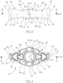
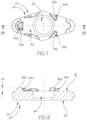
- the embodiment relates to an assembly 20 of a generally rhombus-shaped reversible cutting insert 22 and a support seat 24, as shown in Figs. 1 and 2 .
- the cutting insert 22 has two opposing rhombus-shaped end surfaces 26 interconnected by a continuous peripheral surface 28, with the peripheral side surface 28 having alternating obtuse and acute corner surfaces 30, 32 separated by four side surfaces 34.
- a nose cutting edge 36 is formed at the intersection of each acute corner surface 32 and each end surface 26, and each end surface 26 has a corner abutment surface 38 adjacent each nose cutting edge 36 and a rake surface 48 located therebetween.
- the cutting insert 22 may preferably be manufactured by form pressing and sintering a cemented carbide, such as tungsten carbide, and may be coated or uncoated.
- a median plane M located between the two opposing end surfaces 26 intersects the peripheral surface 28, and the cutting insert 22 is indexable about an insert axis A1 perpendicular to the median plane M.
- each end surface 26 has two cutting sections that are 180° rotationally apart about the insert axis A1.
- a longitudinal plane P1 containing the insert axis A1 bisects the two acute corner surfaces 32 and the four nose cutting edges 36.
- the cutting insert 22 may exhibit mirror symmetry about the median plane M.
- each corner abutment surface 38 is located closer to the median plane M than a nose point N1 located at the intersection of its adjacent nose cutting edge 36 and the longitudinal plane P1.
- no point on each end surface 26 may be located further from the median plane M than the two nose points N1 associated therewith.
- each corner abutment surface 38 may be entirely located closer to the median plane M than any point along its adjacent nose cutting edge 36.
- the two corner abutment surfaces 38 associated with each end surface 26 may be coplanar and parallel to the median plane M.
- a closest point on each end surface 26 from the median plane M may be contained in one of the two corner abutment surfaces 38 associated therewith.
- the longitudinal plane P1 may bisect the two corner abutment surfaces 38 associated with each end surface 26.
- each end surface 26 may have exactly two corner abutment surfaces 38.
- the cutting insert 22 may exhibit mirror symmetry about the longitudinal plane P1.
- the median plane M intersects each side surface 34 to form a side boundary line Ls, and two side boundary lines L s converge towards the same acute corner surface 32 to form an acute nose corner angle ⁇ 1.
- the nose corner angle ⁇ 1 is less than 60°, and suitable for profiling turning operations.
- a lateral plane P2 containing the insert axis A1 bisects the two obtuse corner surfaces 30.
- the cutting insert 22 may exhibit mirror symmetry about the lateral plane P2.
- the longitudinal plane P1 may be perpendicular to the lateral plane P2.
- the median plane M, the longitudinal plane P1 and the lateral plane P2 may be mutually perpendicular to one another, with the insert axis A1 being located at the intersection of the longitudinal plane P1 and the lateral plane P2, a longitudinal axis A2 being located at the intersection of the median plane M and the longitudinal plane P1, and a lateral axis A3 being located at the intersection of the median plane M and the lateral plane P2.
- the insert may be mirror symmetric about all three planes M, P1 and P2.
- the insert may have 180° rotational symmetry about all three axes A1, A2 and A3.
- the insert may be mirror symmetric about all three planes M, P1 and P2 and also 180° rotationally symmetric about all three axes A1, A2 and A3.
- At least one inner abutment surface 40a, 40b is entirely located on one side of the lateral plane P2, and at least one inner abutment surface 40a, 40b is entirely located on the opposite side of the lateral plane P2.
- the at least two inner abutment surfaces 40a, 40b associated with each end surface 26 may be coplanar and parallel to the median plane M.
- the at least two inner abutment surfaces 40a, 40b associated with each end surface 26 may be entirely located closer to the median plane M than the two nose points N1 associated with the same end surface 26.
- the two corner abutment surfaces 38 and the at least two inner abutment surfaces 40a, 40b associated with each end surface 26 may be coplanar.
- each inner abutment surface 40a, 40b may intersect at least one of the four side surfaces 34.
- each end surface 26 may have exactly two spaced apart inner abutment surfaces 40a, 40b located on each side of the lateral plane P2.
- the support seat 24 comprises a seat surface 42 with a plurality of supporting members 44a, 44b, 44c protruding therefrom, each supporting member 44a, 44b, 44c having a supporting surface 46a, 46b, 46c in contact with the end surface 26 facing the support seat 24.
- regions of contact between the cutting insert 22 and the support seat 24 are represented by cross-hatching in in Fig. 2 .
- the plurality of supporting surfaces 46a, 46b, 46c may be coplanar.
- the support seat 24 can be manufactured with increased efficiency.
- each index position of the cutting insert 22 only one of the two corner abutment surfaces 38 of the end surface 26 facing the support seat 24 is in operative contact with the support seat 24, at a first supporting surface 46a , and only the at least one inner abutment surface 40a , 40b of the end surface 26 facing the support seat 24 located on the opposite side of the lateral plane P2 from the operative corner abutment surface 38 is in contact with the support seat 24 at the at least one remaining supporting surface 46b , 46c .
- no other portion of the end surface 26 facing the support seat 24 and located on the same side of the lateral plane P2 may be in contact with the support seat 24.
- the assembly 20 is configured with exactly three spaced apart contact zones between the end surface 26 facing the support seat 24 and the support seat 24, thus enabling the cutting insert 22 to be retained on the support seat 24 without being over-constrained.
- This configuration can be achieved when the two spaced apart inner abutment surfaces 40a, 40b located on the opposite side of the lateral plane P2 from the operative corner abutment surface 38 are in contact with two corresponding supporting surfaces 46b , 46c , as shown in Figs. 2 , 4 and 7 , or alternatively, when the two spaced apart inner abutment surfaces 40a , 40b located on the opposite side of the lateral plane P2 from the operative corner abutment surface 38 are in contact with a single supporting surface (not shown in the figures).
- a clamping force between the cutting insert 22 and the support seat 24 may be applied at a central region of an imaginary triangle delimited by the three spaced apart contact zones, thus enabling the cutting insert 22 to be retained on the support seat 24 with a high level of stability.
- the assembly 20 may still be configured with exactly three spaced apart contact zones, by virtue of the single inner abutment surface located on the opposite side of the lateral plane P2 from the operative corner abutment surface 38 being in contact with two spaced apart supporting surfaces 46b , 46c .
- the operative nose cutting edge 36 may be located on the opposite end surface 26 from the operative corner abutment surface 38 and on the same side of the lateral plane P2 as the operative corner abutment surface 38.
- a first imaginary straight line L1 containing one of the nose points N1 and a radially outermost point No of the adjacent corner abutment surface 38 forms an acute first angle ⁇ 1 with the median plane M.
- the first angle ⁇ 1 may be greater than 25°.
- the operative corner abutment surface 38 is advantageously located 'under' the operative nose cutting edge 36, thus enabling the effective transmission of cutting forces through the cutting insert 22 and into the support seat 24.
- Effective transmission of cutting forces through the cutting insert 22 and into the support seat 24 is particularly preferable for embodiments of the present invention where the cutting insert 22 has slender nose cutting corners and the nose corner angle ⁇ 1 is less than 60°.
- each corner abutment surface 38 is located a first height h1 above the median plane M, and each nose point N1 is located a second height h2 above the median plane M.
- the first height h1 may be less than three quarters of the second height h2, i.e. h1 ⁇ h2 *3/4.
- the cutting insert 22 is advantageously compact in a direction transverse to the median plane M, resulting in reduced material costs and greater suitability for internal turning operations.
- a ramp surface 50 is located between each rake surface 48 and its associated corner abutment surface 38.
- a second imaginary straight line L2 tangential to a ramp point NR on each ramp surface 50 forms an acute second angle ⁇ 2 with the median plane M.
- the second angle ⁇ 2 is greater than the first angle ⁇ 1.
- each second imaginary straight line L2 intersects the median plane M at an inner axial point N2.
- each inner axial point N2 may be located closer to the insert axis A1 than its associated ramp point NR.
- each ramp surface 50 may extend from its associated rake surface 48 to its associated corner abutment surface 38, and as shown in Fig. 5 , in a cross-sectional view of the cutting insert 22 taken along the longitudinal plane P1, the radially outermost point No of each corner abutment surface 38 may be coincident with the ramp point NR of its associated ramp surface 50.
- each rake surface 48 may extend from its associated nose cutting edge 36 to its associated ramp surface 50, and in a cross-sectional view of the cutting insert 22 taken along the longitudinal plane P1, as shown in Fig. 5 , each rake surface 48 may extend continuously towards the median plane M from its associated nose cutting edge 36 to its associated ramp surface 50.
- each nose cutting edge 36 is typically honed, having no negative land surface associated therewith.
- the median plane M intersects each acute corner surface 32 to form a nose boundary line LN
- the longitudinal plane P1 intersects each nose boundary line LN at an outer axial point N3.
- each outer axial point N3 may be located closer to the insert axis A1 than the two nose points N1 associated with the same acute corner surface 32.
- each end surface 26 may intersect the peripheral side surface 28 to form a peripheral edge 52, and in a cross-sectional view of the cutting insert 22 taken along the median plane M, as shown in Fig. 6 , each nose boundary line LN may be entirely located inside the visible peripheral edge 52.
- the cutting insert 22 takes the form of a double-positive type cutting insert, thus enabling turning operations to be performed with an increased positive rake angle, whilst maintaining sufficient clearance between the acute corner surface 32 and a workpiece (not shown).
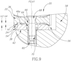
- the support seat 24 may be in the form of a shim 54 removably retained in an insert receiving pocket 56 of a tool holder 58 by means of a threaded bushing 60.
- the shim 54 may preferably be manufactured from cemented carbide or another material which is harder than the material of the insert receiving pocket 56.
- the shim 54 may have a flat base surface 62 opposing the seat surface 42, and a shim bore 64 may intersect both the base surface 62 and the seat surface 42.
- the threaded bushing 60 may be located in the shim bore 64 and threadingly engage the receiving pocket 56.
- an insert bore 66 may extend coaxially with the insert axis A1 and intersect the two end surfaces 26 of the cutting insert 22.
- a clamping screw 68 may be located in the insert bore 66 and threadingly engage a threaded bore 70 in the threaded bushing 60 to apply the clamping force.
- each nose point N1 is located a third height h3 above its associated corner abutment surface 38, and the first supporting surface 46a is located a fourth height h4 above the seat surface 42.
- the third height h3 may be greater than the fourth height h4.
- the insert receiving pocket 56 may include two pocket walls 72a, 72b transverse to the seat surface 42 of the shim 54.
- the two side surfaces 34 of the cutting insert 22 located on the opposite side of the lateral plane P2 from the operative corner abutment surface 38 may be in contact with the two pocket walls 72a, 72b.
- Contact between the cutting insert 22 and the two pocket walls 72a, 72b may be generated by the insert bore 66 and the threaded bore 70 being eccentric to each other, and a component of the clamping force from the clamping screw 68 being directed transverse to the insert axis A1.
- the shim 54 may be non-indexable.
- each end surface 26 of the cutting insert 22 may have a male-type lateral member 74 extending between and intersecting the two obtuse corner surfaces 30, and each lateral member 74 may have a raised lateral surface 76 having a fifth height h5 above the median plane M.
- each raised lateral surface 76 may be located closer to the median plane M than the two nose points N1 associated with the same end surface 26 (i.e., h2 > h5 ), and each raised lateral surface 76 may be located further from the median plane M than the at least two inner abutment surfaces 40a, 40b of the same end surface 26.
- the raised lateral surface 76 may be parallel to the median plane M.
- the insert bore 66 may intersect the raised lateral surface 76 of each lateral member 74.
Landscapes
- Engineering & Computer Science (AREA)
- Mechanical Engineering (AREA)
- Milling Processes (AREA)
- Cutting Tools, Boring Holders, And Turrets (AREA)
- Absorbent Articles And Supports Therefor (AREA)
- Processing Of Stones Or Stones Resemblance Materials (AREA)
- Earth Drilling (AREA)
- Harvester Elements (AREA)
Claims (7)
- Allgemein rhombus-förmiger umkehrbarer Schneideinsatz (22), aufweisend:zwei gegenüberliegende Endflächen (26), die durch eine kontinuierliche Umfangsfläche (28) miteinander verbunden sind, wobei die Umfangsseitenfläche (28) abwechselnd stumpfwinklige und spitzwinklige Eckflächen (30, 32) hat, die durch vier Seitenflächen (34) voneinander getrennt sind;eine Mittelebene (M), die zwischen den zwei gegenüberliegenden Endflächen (26) angeordnet ist und die Umfangsfläche (28) kreuzt,eine Einsatzachse (A1), die senkrecht zu der Mittelebene (M) ist und um die der Schneideinsatz (22) wendbar ist,eine Nasenschneidkante (36), die an der Kreuzung jeder spitzwinkligen Eckfläche (32) und jeder Endfläche (26) gebildet ist,eine Längsebene (P1), die die Einsatzachse (A1) enthält und die vier Nasenschneidkanten (36) halbiert,wobei jede Endfläche (26) eine Eckanlagefläche (38) angrenzend an jede Nasenschneidkante (36) und eine dazwischen angeordnete Spanfläche (48) hat,einen Nasenpunkt (N1), der sich an einer Kreuzung jeder Nasenschneidkante (36) und der Längsebene (P1) befindet, undwobei jede Eckanlagefläche (38) näher an der Mittelebene (M) angeordnet ist als ihr angrenzender Nasenpunkt (N1),wobei:die Mittelebene (M) jede Seitenfläche (34) kreuzt, um eine Seitenrandlinie (Ls) zu bilden; undin einer entlang der Längsebene (P1) genommenen Querschnittansicht des Schneideinsatzes (22) eine erste imaginäre gerade Linie (L1), die irgendeinen der Nasenpunkte (N1) und einen radial äußersten Punkt (No) der angrenzenden Eckanlagefläche (38) enthält, mit der Mittelebene (M) einen spitzen ersten Winkel ((31) bildet, der größer als 25° ist;dadurch gekennzeichnet, dasszwei Seitenrandlinien (Ls) zu der gleichen spitzwinkligen Eckfläche (32) konvergieren, um einen spitzen Naseneckwinkel (α1) zu bilden, der kleiner als 60° ist;eine Rampenfläche (50) zwischen jeder Spanfläche (48) und deren zugehöriger Eckanlagefläche (38) angeordnet ist; undin der entlang der Längsebene (P1) genommenen Querschnittansicht des Schneideinsatzes (22) eine zweite imaginäre gerade Linie (L2), die tangential zu einem Rampenpunkt (NR) an der Rampenfläche (50) ist, mit der Mittelebene (M) einen spitzen zweiten Winkel (β2) bildet, undder zweite Winkel (β2) größer als der erste Winkel (β1) ist.
- Schneideinsatz (22) nach Anspruch 1, wobei kein Punkt an jeder Endfläche (26) weiter weg von der Mittelebne (M) angeordnet ist als die zwei zugehörigen Nasenpunkte (N1).
- Schneideinsatz (22) nach Anspruch 1 oder 2, wobei jede Eckanlagefläche (38) in Gänze näher an der Mittelebene (M) angeordnet ist als irgendein Punkt ihrer angrenzenden Nasenschneidkante (36).
- Schneideinsatz (22) nach einem der Ansprüche 1 bis 3, wobei:
jede Endfläche (26) ein laterales Element (74) männlichen Typs hat, das sich zwischen den zwei stumpfwinkligen Eckflächen (30) erstreckt und diese kreuzt. - Schneideinsatz (22) nach Anspruch 4, wobei:
jedes laterale Element (74) eine vorspringende laterale Oberfläche (76) hat, die näher an der Mittelebene (M) angeordnet ist als die der gleichen Endfläche (26) zugehörigen zwei Nasenpunkte (N1). - Schneideinsatz (22) nach Anspruch 5, wobei:
eine Einsatzbohrung (66) sich koaxial mit der Einsatzachse (A1) erstreckt und die vorspringende laterale Oberfläche (76) jedes lateralen Elements (74) kreuzt. - Schneideinsatz (22) nach Anspruch 5, wobei in der entlang der Längsebene (P1) genommenen Querschnittansicht des Schneideinsatzes (22):der radial äußerste Punkt (No) jeder Eckanlagefläche (38) eine erste Höhe (h1) oberhalb der Mittelebene (M) angeordnet ist,jede vorspringende laterale Oberfläche (76) eine fünfte Höhe (h5) oberhalb der Mittelebene (M) angeordnet ist, unddie fünfte Höhe (h5) größer als die erste Höhe (h1) ist.
Applications Claiming Priority (2)
| Application Number | Priority Date | Filing Date | Title |
|---|---|---|---|
| US14/742,874 US9802255B2 (en) | 2015-06-18 | 2015-06-18 | Rhombus-shaped reversible cutting insert and support seat therefor |
| PCT/IL2016/050539 WO2016203462A1 (en) | 2015-06-18 | 2016-05-24 | Assembly comprising rhombus-shaped insert and support seat and rhombus-shaped reversible cutting insert |
Publications (2)
| Publication Number | Publication Date |
|---|---|
| EP3310511A1 EP3310511A1 (de) | 2018-04-25 |
| EP3310511B1 true EP3310511B1 (de) | 2024-04-03 |
Family
ID=56194532
Family Applications (1)
| Application Number | Title | Priority Date | Filing Date |
|---|---|---|---|
| EP16731668.6A Active EP3310511B1 (de) | 2015-06-18 | 2016-05-24 | Rhombus-förmiger umkehrbarer schneideinsatz |
Country Status (14)
| Country | Link |
|---|---|
| US (1) | US9802255B2 (de) |
| EP (1) | EP3310511B1 (de) |
| JP (1) | JP6966329B2 (de) |
| KR (1) | KR102478774B1 (de) |
| CN (1) | CN107708901B (de) |
| BR (1) | BR112017025114B1 (de) |
| CA (1) | CA2988035C (de) |
| ES (1) | ES2977384T3 (de) |
| IL (1) | IL255553B (de) |
| PL (1) | PL3310511T3 (de) |
| PT (1) | PT3310511T (de) |
| RU (1) | RU2715266C2 (de) |
| TW (1) | TWI750121B (de) |
| WO (1) | WO2016203462A1 (de) |
Families Citing this family (8)
| Publication number | Priority date | Publication date | Assignee | Title |
|---|---|---|---|---|
| CN107020395B (zh) * | 2017-05-31 | 2019-12-03 | 玉环卡布里尔刀具科技有限公司 | 一种用于各类铜材料外圆与内孔加工的聚晶金刚石刀具 |
| RU2661223C1 (ru) * | 2017-12-11 | 2018-07-16 | Нина Алексеевна Корюкина | Режущая пластина и сборный резец |
| KR102393186B1 (ko) | 2018-03-28 | 2022-05-02 | 대구텍 유한책임회사 | 인서트 및 이를 포함하는 절삭 공구 조립체 |
| JP6617894B2 (ja) * | 2018-05-16 | 2019-12-11 | 株式会社タンガロイ | 切削インサート及び切削工具 |
| KR102146314B1 (ko) * | 2018-12-20 | 2020-08-20 | 한국야금 주식회사 | 절삭인서트 및 이를 장착한 절삭공구 |
| EP4091749A1 (de) * | 2021-05-20 | 2022-11-23 | AB Sandvik Coromant | Metallschneidendes drehwerkzeug |
| US11717895B2 (en) * | 2021-05-21 | 2023-08-08 | Taegutec Ltd. | Cutting insert and cutting tool assembly including same |
| JP7692062B2 (ja) * | 2022-01-05 | 2025-06-12 | 京セラ株式会社 | 切削インサート、切削工具、及び切削加工物の製造方法 |
Family Cites Families (26)
| Publication number | Priority date | Publication date | Assignee | Title |
|---|---|---|---|---|
| US3760474A (en) * | 1971-11-04 | 1973-09-25 | Warner Swasey Co | Reversible blade-like cutoff tool |
| SU755443A1 (en) * | 1977-05-19 | 1980-08-15 | Petr B Grinberg | Cutting blade |
| US4340324A (en) | 1980-08-28 | 1982-07-20 | Kennametal Inc. | Cutting insert |
| SU1266664A1 (ru) | 1985-05-17 | 1986-10-30 | Всесоюзный заочный машиностроительный институт | Режуща вставка |
| DE19653921B4 (de) | 1995-12-27 | 2009-05-07 | Widia Gmbh | Schneidwerkzeugeinheit aus einem Werkzeughalter und einer Wendeschneidplatte |
| JP2000107911A (ja) * | 1998-10-05 | 2000-04-18 | Mitsubishi Materials Corp | スローアウェイチップ |
| DE10207768A1 (de) * | 2001-07-26 | 2003-03-06 | Ceramtec Ag | Schneideinsatz mit Spannmulde und Schneidwerkzeug |
| JP3812473B2 (ja) * | 2001-11-20 | 2006-08-23 | 三菱マテリアル株式会社 | スローアウェイチップ |
| SE526586C2 (sv) * | 2003-11-25 | 2005-10-11 | Sandvik Intellectual Property | Verktyg för spånavskiljande bearbetning innefattande en han/hon-koppling mellan skärdel och hållardel |
| SE527613C2 (sv) * | 2004-10-15 | 2006-04-25 | Seco Tools Ab | Verktyg för skärande bearbetning med en underläggsplatta med urtagningar |
| SE528811C2 (sv) * | 2005-03-16 | 2007-02-20 | Sandvik Intellectual Property | Skär och verktyg för spånavskiljande bearbetning med vinklade ingreppsmedel, samt tillsats för dylika verktyg |
| JP4797526B2 (ja) * | 2005-09-13 | 2011-10-19 | 株式会社タンガロイ | スローアウェイチップ |
| DE102006017074A1 (de) * | 2006-04-10 | 2007-10-11 | Walter Ag | Unterlegplatte für doppelseitige Wendeschneideinsätze |
| CN201095002Y (zh) * | 2007-10-18 | 2008-08-06 | 上海美恩精密工具有限公司 | 立方氮化硼孔型刀具 |
| RU2349425C1 (ru) * | 2007-11-27 | 2009-03-20 | Нина Алексеевна Корюкина | Режущая пластина и сборный режущий инструмент (варианты) |
| SE534512C2 (sv) * | 2009-06-24 | 2011-09-13 | Sandvik Intellectual Property | Verktyg för spånavskiljande bearbetning samt solitt indexerbart skär och solid grundkropp härför |
| KR101606935B1 (ko) | 2009-07-09 | 2016-03-28 | 대구텍 유한회사 | 양면 인덱서블 절삭 인서트와 보강재의 조립체 |
| KR20120116933A (ko) * | 2010-02-09 | 2012-10-23 | 미쓰비시 마테리알 가부시키가이샤 | 절삭 인서트, 시트 부재, 및 블레이트 팁 교환 절삭 공구 |
| SE536295C2 (sv) * | 2011-09-23 | 2013-08-06 | Sandvik Intellectual Property | Månghörnigt svarvskär med förbättrad spånkontroll |
| US8821079B2 (en) * | 2012-03-06 | 2014-09-02 | Iscar, Ltd. | Cutting tool and cutting insert therefor |
| US8814480B2 (en) * | 2012-04-17 | 2014-08-26 | Iscar, Ltd. | Cutting insert chip-control arrangement |
| CN203390226U (zh) * | 2012-12-13 | 2014-01-15 | 段仕新 | 一种舍弃式车刀系统 |
| SE536986C2 (sv) | 2013-03-20 | 2014-11-25 | Sandvik Intellectual Property | Månghörnigt svarvskär med spånkontrollerande styrytor |
| US9120156B2 (en) * | 2013-03-26 | 2015-09-01 | Iscar, Ltd. | Rhombus-shaped indexable cutting insert and cutting tool |
| CN204159901U (zh) * | 2014-10-22 | 2015-02-18 | 苏州航天紧固件有限公司 | 一种耐疲劳台式车床用刀具 |
| CN204396933U (zh) * | 2014-12-23 | 2015-06-17 | 苏州欧美克合金工具有限公司 | 一种数控可转位刀具 |
-
2015
- 2015-06-18 US US14/742,874 patent/US9802255B2/en active Active
-
2016
- 2016-05-24 ES ES16731668T patent/ES2977384T3/es active Active
- 2016-05-24 JP JP2017556963A patent/JP6966329B2/ja active Active
- 2016-05-24 PT PT167316686T patent/PT3310511T/pt unknown
- 2016-05-24 CN CN201680035189.5A patent/CN107708901B/zh active Active
- 2016-05-24 EP EP16731668.6A patent/EP3310511B1/de active Active
- 2016-05-24 RU RU2018101699A patent/RU2715266C2/ru active
- 2016-05-24 PL PL16731668.6T patent/PL3310511T3/pl unknown
- 2016-05-24 KR KR1020177035584A patent/KR102478774B1/ko active Active
- 2016-05-24 BR BR112017025114-0A patent/BR112017025114B1/pt active IP Right Grant
- 2016-05-24 WO PCT/IL2016/050539 patent/WO2016203462A1/en not_active Ceased
- 2016-05-24 CA CA2988035A patent/CA2988035C/en active Active
- 2016-06-03 TW TW105117659A patent/TWI750121B/zh active
-
2017
- 2017-11-09 IL IL255553A patent/IL255553B/en active IP Right Grant
Also Published As
| Publication number | Publication date |
|---|---|
| US20160368062A1 (en) | 2016-12-22 |
| KR20180018547A (ko) | 2018-02-21 |
| JP2018518375A (ja) | 2018-07-12 |
| EP3310511A1 (de) | 2018-04-25 |
| ES2977384T3 (es) | 2024-08-22 |
| RU2018101699A (ru) | 2019-07-18 |
| IL255553A (en) | 2018-01-31 |
| TW201701972A (zh) | 2017-01-16 |
| US9802255B2 (en) | 2017-10-31 |
| KR102478774B1 (ko) | 2022-12-20 |
| TWI750121B (zh) | 2021-12-21 |
| CA2988035A1 (en) | 2016-12-22 |
| IL255553B (en) | 2021-01-31 |
| CA2988035C (en) | 2023-09-19 |
| RU2018101699A3 (de) | 2019-10-02 |
| BR112017025114B1 (pt) | 2021-08-31 |
| PT3310511T (pt) | 2024-04-22 |
| WO2016203462A1 (en) | 2016-12-22 |
| CN107708901A (zh) | 2018-02-16 |
| BR112017025114A2 (pt) | 2018-07-31 |
| CN107708901B (zh) | 2019-09-13 |
| PL3310511T3 (pl) | 2024-06-24 |
| RU2715266C2 (ru) | 2020-02-26 |
| JP6966329B2 (ja) | 2021-11-17 |
Similar Documents
| Publication | Publication Date | Title |
|---|---|---|
| CA2988035C (en) | Assembly comprising rhombus-shaped insert and support seat and rhombus-shaped reversible cutting insert | |
| EP3199283B1 (de) | Schneideeinsatz und rotierendes schneidewerkzeug mit austauschbarer klinge | |
| EP2978552B1 (de) | Rautenförmiger indexierbarer schneideinsatz und schneidwerkzeug | |
| EP1677934B1 (de) | Tangentialschneideinsatz und fräswerkzeug | |
| EP2818269B1 (de) | Schneideinsatz und schneidwerkzeug mit auswechselbarer schneidkante | |
| US8337123B2 (en) | Cutting insert, cutting tool, and cutting method using the cutting tool | |
| EP3241638B1 (de) | Schneideinsatz, werkzeugkörper und schneidwerkzeug | |
| CA2846006C (en) | Cutting tool and cutting insert having a clamping bore with spaced apart clamping portions | |
| EP3338931B1 (de) | Schneideeinsatz und schneidewerkzeug | |
| US9776258B2 (en) | Double-sided, trigon cutting insert with rounded minor cutting edge and cutting tool therefor | |
| EP3266547A1 (de) | Schneideinsatz und schneidwerkzeug mit ersetzbarer schneidkante | |
| US7264425B1 (en) | Tool | |
| US9623495B2 (en) | Cutting insert with asymmetric cutting edge | |
| WO2016093275A1 (ja) | 切削インサート、工具ボデーおよび切削工具 | |
| KR20200004798A (ko) | 리딩 및 트레일링 부품 절삭 변부들을 가진 분할 절삭 변부를 가지는 절삭 인서트 | |
| US20180304387A1 (en) | Cutting tool and cutting insert | |
| JP2007196346A (ja) | スローアウェイインサートおよびそれを装着した切削工具 | |
| JP2009184086A (ja) | スローアウェイチップ |
Legal Events
| Date | Code | Title | Description |
|---|---|---|---|
| STAA | Information on the status of an ep patent application or granted ep patent |
Free format text: STATUS: THE INTERNATIONAL PUBLICATION HAS BEEN MADE |
|
| PUAI | Public reference made under article 153(3) epc to a published international application that has entered the european phase |
Free format text: ORIGINAL CODE: 0009012 |
|
| STAA | Information on the status of an ep patent application or granted ep patent |
Free format text: STATUS: REQUEST FOR EXAMINATION WAS MADE |
|
| 17P | Request for examination filed |
Effective date: 20171206 |
|
| AK | Designated contracting states |
Kind code of ref document: A1 Designated state(s): AL AT BE BG CH CY CZ DE DK EE ES FI FR GB GR HR HU IE IS IT LI LT LU LV MC MK MT NL NO PL PT RO RS SE SI SK SM TR |
|
| AX | Request for extension of the european patent |
Extension state: BA ME |
|
| DAV | Request for validation of the european patent (deleted) | ||
| DAX | Request for extension of the european patent (deleted) | ||
| STAA | Information on the status of an ep patent application or granted ep patent |
Free format text: STATUS: EXAMINATION IS IN PROGRESS |
|
| 17Q | First examination report despatched |
Effective date: 20220516 |
|
| GRAP | Despatch of communication of intention to grant a patent |
Free format text: ORIGINAL CODE: EPIDOSNIGR1 |
|
| STAA | Information on the status of an ep patent application or granted ep patent |
Free format text: STATUS: GRANT OF PATENT IS INTENDED |
|
| INTG | Intention to grant announced |
Effective date: 20230323 |
|
| GRAJ | Information related to disapproval of communication of intention to grant by the applicant or resumption of examination proceedings by the epo deleted |
Free format text: ORIGINAL CODE: EPIDOSDIGR1 |
|
| STAA | Information on the status of an ep patent application or granted ep patent |
Free format text: STATUS: EXAMINATION IS IN PROGRESS |
|
| INTC | Intention to grant announced (deleted) | ||
| GRAP | Despatch of communication of intention to grant a patent |
Free format text: ORIGINAL CODE: EPIDOSNIGR1 |
|
| STAA | Information on the status of an ep patent application or granted ep patent |
Free format text: STATUS: GRANT OF PATENT IS INTENDED |
|
| INTG | Intention to grant announced |
Effective date: 20231108 |
|
| GRAS | Grant fee paid |
Free format text: ORIGINAL CODE: EPIDOSNIGR3 |
|
| GRAA | (expected) grant |
Free format text: ORIGINAL CODE: 0009210 |
|
| STAA | Information on the status of an ep patent application or granted ep patent |
Free format text: STATUS: THE PATENT HAS BEEN GRANTED |
|
| AK | Designated contracting states |
Kind code of ref document: B1 Designated state(s): AL AT BE BG CH CY CZ DE DK EE ES FI FR GB GR HR HU IE IS IT LI LT LU LV MC MK MT NL NO PL PT RO RS SE SI SK SM TR |
|
| P01 | Opt-out of the competence of the unified patent court (upc) registered |
Effective date: 20240228 |
|
| REG | Reference to a national code |
Ref country code: GB Ref legal event code: FG4D |
|
| REG | Reference to a national code |
Ref country code: CH Ref legal event code: EP |
|
| REG | Reference to a national code |
Ref country code: PT Ref legal event code: SC4A Ref document number: 3310511 Country of ref document: PT Date of ref document: 20240422 Kind code of ref document: T Free format text: AVAILABILITY OF NATIONAL TRANSLATION Effective date: 20240417 |
|
| REG | Reference to a national code |
Ref country code: IE Ref legal event code: FG4D |
|
| REG | Reference to a national code |
Ref country code: DE Ref legal event code: R096 Ref document number: 602016086653 Country of ref document: DE |
|
| REG | Reference to a national code |
Ref country code: SE Ref legal event code: TRGR |
|
| REG | Reference to a national code |
Ref country code: LT Ref legal event code: MG9D |
|
| REG | Reference to a national code |
Ref country code: NL Ref legal event code: MP Effective date: 20240403 |
|
| REG | Reference to a national code |
Ref country code: AT Ref legal event code: UEP Ref document number: 1671717 Country of ref document: AT Kind code of ref document: T Effective date: 20240403 |
|
| REG | Reference to a national code |
Ref country code: ES Ref legal event code: FG2A Ref document number: 2977384 Country of ref document: ES Kind code of ref document: T3 Effective date: 20240822 |
|
| PG25 | Lapsed in a contracting state [announced via postgrant information from national office to epo] |
Ref country code: NL Free format text: LAPSE BECAUSE OF FAILURE TO SUBMIT A TRANSLATION OF THE DESCRIPTION OR TO PAY THE FEE WITHIN THE PRESCRIBED TIME-LIMIT Effective date: 20240403 |
|
| PG25 | Lapsed in a contracting state [announced via postgrant information from national office to epo] |
Ref country code: NL Free format text: LAPSE BECAUSE OF FAILURE TO SUBMIT A TRANSLATION OF THE DESCRIPTION OR TO PAY THE FEE WITHIN THE PRESCRIBED TIME-LIMIT Effective date: 20240403 |
|
| PG25 | Lapsed in a contracting state [announced via postgrant information from national office to epo] |
Ref country code: IS Free format text: LAPSE BECAUSE OF FAILURE TO SUBMIT A TRANSLATION OF THE DESCRIPTION OR TO PAY THE FEE WITHIN THE PRESCRIBED TIME-LIMIT Effective date: 20240803 |
|
| PG25 | Lapsed in a contracting state [announced via postgrant information from national office to epo] |
Ref country code: BG Free format text: LAPSE BECAUSE OF FAILURE TO SUBMIT A TRANSLATION OF THE DESCRIPTION OR TO PAY THE FEE WITHIN THE PRESCRIBED TIME-LIMIT Effective date: 20240403 |
|
| PG25 | Lapsed in a contracting state [announced via postgrant information from national office to epo] |
Ref country code: HR Free format text: LAPSE BECAUSE OF FAILURE TO SUBMIT A TRANSLATION OF THE DESCRIPTION OR TO PAY THE FEE WITHIN THE PRESCRIBED TIME-LIMIT Effective date: 20240403 Ref country code: FI Free format text: LAPSE BECAUSE OF FAILURE TO SUBMIT A TRANSLATION OF THE DESCRIPTION OR TO PAY THE FEE WITHIN THE PRESCRIBED TIME-LIMIT Effective date: 20240403 |
|
| PG25 | Lapsed in a contracting state [announced via postgrant information from national office to epo] |
Ref country code: GR Free format text: LAPSE BECAUSE OF FAILURE TO SUBMIT A TRANSLATION OF THE DESCRIPTION OR TO PAY THE FEE WITHIN THE PRESCRIBED TIME-LIMIT Effective date: 20240704 |
|
| PG25 | Lapsed in a contracting state [announced via postgrant information from national office to epo] |
Ref country code: LV Free format text: LAPSE BECAUSE OF FAILURE TO SUBMIT A TRANSLATION OF THE DESCRIPTION OR TO PAY THE FEE WITHIN THE PRESCRIBED TIME-LIMIT Effective date: 20240403 |
|
| PG25 | Lapsed in a contracting state [announced via postgrant information from national office to epo] |
Ref country code: NO Free format text: LAPSE BECAUSE OF FAILURE TO SUBMIT A TRANSLATION OF THE DESCRIPTION OR TO PAY THE FEE WITHIN THE PRESCRIBED TIME-LIMIT Effective date: 20240703 Ref country code: LV Free format text: LAPSE BECAUSE OF FAILURE TO SUBMIT A TRANSLATION OF THE DESCRIPTION OR TO PAY THE FEE WITHIN THE PRESCRIBED TIME-LIMIT Effective date: 20240403 Ref country code: IS Free format text: LAPSE BECAUSE OF FAILURE TO SUBMIT A TRANSLATION OF THE DESCRIPTION OR TO PAY THE FEE WITHIN THE PRESCRIBED TIME-LIMIT Effective date: 20240803 Ref country code: HR Free format text: LAPSE BECAUSE OF FAILURE TO SUBMIT A TRANSLATION OF THE DESCRIPTION OR TO PAY THE FEE WITHIN THE PRESCRIBED TIME-LIMIT Effective date: 20240403 Ref country code: GR Free format text: LAPSE BECAUSE OF FAILURE TO SUBMIT A TRANSLATION OF THE DESCRIPTION OR TO PAY THE FEE WITHIN THE PRESCRIBED TIME-LIMIT Effective date: 20240704 Ref country code: FI Free format text: LAPSE BECAUSE OF FAILURE TO SUBMIT A TRANSLATION OF THE DESCRIPTION OR TO PAY THE FEE WITHIN THE PRESCRIBED TIME-LIMIT Effective date: 20240403 Ref country code: BG Free format text: LAPSE BECAUSE OF FAILURE TO SUBMIT A TRANSLATION OF THE DESCRIPTION OR TO PAY THE FEE WITHIN THE PRESCRIBED TIME-LIMIT Effective date: 20240403 Ref country code: RS Free format text: LAPSE BECAUSE OF FAILURE TO SUBMIT A TRANSLATION OF THE DESCRIPTION OR TO PAY THE FEE WITHIN THE PRESCRIBED TIME-LIMIT Effective date: 20240703 |
|
| REG | Reference to a national code |
Ref country code: DE Ref legal event code: R097 Ref document number: 602016086653 Country of ref document: DE |
|
| PG25 | Lapsed in a contracting state [announced via postgrant information from national office to epo] |
Ref country code: DK Free format text: LAPSE BECAUSE OF FAILURE TO SUBMIT A TRANSLATION OF THE DESCRIPTION OR TO PAY THE FEE WITHIN THE PRESCRIBED TIME-LIMIT Effective date: 20240403 |
|
| PG25 | Lapsed in a contracting state [announced via postgrant information from national office to epo] |
Ref country code: LU Free format text: LAPSE BECAUSE OF NON-PAYMENT OF DUE FEES Effective date: 20240524 |
|
| PG25 | Lapsed in a contracting state [announced via postgrant information from national office to epo] |
Ref country code: EE Free format text: LAPSE BECAUSE OF FAILURE TO SUBMIT A TRANSLATION OF THE DESCRIPTION OR TO PAY THE FEE WITHIN THE PRESCRIBED TIME-LIMIT Effective date: 20240403 |
|
| PG25 | Lapsed in a contracting state [announced via postgrant information from national office to epo] |
Ref country code: SK Free format text: LAPSE BECAUSE OF FAILURE TO SUBMIT A TRANSLATION OF THE DESCRIPTION OR TO PAY THE FEE WITHIN THE PRESCRIBED TIME-LIMIT Effective date: 20240403 Ref country code: RO Free format text: LAPSE BECAUSE OF FAILURE TO SUBMIT A TRANSLATION OF THE DESCRIPTION OR TO PAY THE FEE WITHIN THE PRESCRIBED TIME-LIMIT Effective date: 20240403 |
|
| PG25 | Lapsed in a contracting state [announced via postgrant information from national office to epo] |
Ref country code: SM Free format text: LAPSE BECAUSE OF FAILURE TO SUBMIT A TRANSLATION OF THE DESCRIPTION OR TO PAY THE FEE WITHIN THE PRESCRIBED TIME-LIMIT Effective date: 20240403 |
|
| PG25 | Lapsed in a contracting state [announced via postgrant information from national office to epo] |
Ref country code: SM Free format text: LAPSE BECAUSE OF FAILURE TO SUBMIT A TRANSLATION OF THE DESCRIPTION OR TO PAY THE FEE WITHIN THE PRESCRIBED TIME-LIMIT Effective date: 20240403 Ref country code: SK Free format text: LAPSE BECAUSE OF FAILURE TO SUBMIT A TRANSLATION OF THE DESCRIPTION OR TO PAY THE FEE WITHIN THE PRESCRIBED TIME-LIMIT Effective date: 20240403 Ref country code: RO Free format text: LAPSE BECAUSE OF FAILURE TO SUBMIT A TRANSLATION OF THE DESCRIPTION OR TO PAY THE FEE WITHIN THE PRESCRIBED TIME-LIMIT Effective date: 20240403 Ref country code: LU Free format text: LAPSE BECAUSE OF NON-PAYMENT OF DUE FEES Effective date: 20240524 Ref country code: EE Free format text: LAPSE BECAUSE OF FAILURE TO SUBMIT A TRANSLATION OF THE DESCRIPTION OR TO PAY THE FEE WITHIN THE PRESCRIBED TIME-LIMIT Effective date: 20240403 Ref country code: DK Free format text: LAPSE BECAUSE OF FAILURE TO SUBMIT A TRANSLATION OF THE DESCRIPTION OR TO PAY THE FEE WITHIN THE PRESCRIBED TIME-LIMIT Effective date: 20240403 Ref country code: MC Free format text: LAPSE BECAUSE OF FAILURE TO SUBMIT A TRANSLATION OF THE DESCRIPTION OR TO PAY THE FEE WITHIN THE PRESCRIBED TIME-LIMIT Effective date: 20240403 |
|
| PLBE | No opposition filed within time limit |
Free format text: ORIGINAL CODE: 0009261 |
|
| STAA | Information on the status of an ep patent application or granted ep patent |
Free format text: STATUS: NO OPPOSITION FILED WITHIN TIME LIMIT |
|
| REG | Reference to a national code |
Ref country code: BE Ref legal event code: MM Effective date: 20240531 |
|
| 26N | No opposition filed |
Effective date: 20250106 |
|
| PGFP | Annual fee paid to national office [announced via postgrant information from national office to epo] |
Ref country code: SE Payment date: 20250314 Year of fee payment: 10 |
|
| PG25 | Lapsed in a contracting state [announced via postgrant information from national office to epo] |
Ref country code: IE Free format text: LAPSE BECAUSE OF NON-PAYMENT OF DUE FEES Effective date: 20240524 |
|
| PG25 | Lapsed in a contracting state [announced via postgrant information from national office to epo] |
Ref country code: SI Free format text: LAPSE BECAUSE OF FAILURE TO SUBMIT A TRANSLATION OF THE DESCRIPTION OR TO PAY THE FEE WITHIN THE PRESCRIBED TIME-LIMIT Effective date: 20240403 Ref country code: BE Free format text: LAPSE BECAUSE OF NON-PAYMENT OF DUE FEES Effective date: 20240531 |
|
| PGFP | Annual fee paid to national office [announced via postgrant information from national office to epo] |
Ref country code: CZ Payment date: 20250320 Year of fee payment: 10 |
|
| PGFP | Annual fee paid to national office [announced via postgrant information from national office to epo] |
Ref country code: TR Payment date: 20250324 Year of fee payment: 10 |
|
| PGFP | Annual fee paid to national office [announced via postgrant information from national office to epo] |
Ref country code: DE Payment date: 20250409 Year of fee payment: 10 |
|
| PGFP | Annual fee paid to national office [announced via postgrant information from national office to epo] |
Ref country code: GB Payment date: 20250411 Year of fee payment: 10 |
|
| PGFP | Annual fee paid to national office [announced via postgrant information from national office to epo] |
Ref country code: FR Payment date: 20250414 Year of fee payment: 10 |
|
| PGFP | Annual fee paid to national office [announced via postgrant information from national office to epo] |
Ref country code: CH Payment date: 20250601 Year of fee payment: 10 |
|
| PGFP | Annual fee paid to national office [announced via postgrant information from national office to epo] |
Ref country code: AT Payment date: 20250409 Year of fee payment: 10 |
|
| PG25 | Lapsed in a contracting state [announced via postgrant information from national office to epo] |
Ref country code: CY Free format text: LAPSE BECAUSE OF FAILURE TO SUBMIT A TRANSLATION OF THE DESCRIPTION OR TO PAY THE FEE WITHIN THE PRESCRIBED TIME-LIMIT; INVALID AB INITIO Effective date: 20160524 |
|
| PG25 | Lapsed in a contracting state [announced via postgrant information from national office to epo] |
Ref country code: HU Free format text: LAPSE BECAUSE OF FAILURE TO SUBMIT A TRANSLATION OF THE DESCRIPTION OR TO PAY THE FEE WITHIN THE PRESCRIBED TIME-LIMIT; INVALID AB INITIO Effective date: 20160524 |
|
| PGFP | Annual fee paid to national office [announced via postgrant information from national office to epo] |
Ref country code: ES Payment date: 20250708 Year of fee payment: 10 |
|
| PG25 | Lapsed in a contracting state [announced via postgrant information from national office to epo] |
Ref country code: IT Free format text: LAPSE BECAUSE OF NON-PAYMENT OF DUE FEES Effective date: 20240524 |
|
| PG25 | Lapsed in a contracting state [announced via postgrant information from national office to epo] |
Ref country code: IT Free format text: LAPSE BECAUSE OF NON-PAYMENT OF DUE FEES Effective date: 20240524 |
|
| PGFP | Annual fee paid to national office [announced via postgrant information from national office to epo] |
Ref country code: IT Payment date: 20250321 Year of fee payment: 10 |
|
| PGRI | Patent reinstated in contracting state [announced from national office to epo] |
Ref country code: IT Effective date: 20240930 |
|
| PGFP | Annual fee paid to national office [announced via postgrant information from national office to epo] |
Ref country code: PT Payment date: 20260327 Year of fee payment: 11 |
|
| PGFP | Annual fee paid to national office [announced via postgrant information from national office to epo] |
Ref country code: PL Payment date: 20260327 Year of fee payment: 11 |