EP3310604B1 - Batterieträgeranordnung für ein hybridfahrzeug - Google Patents
Batterieträgeranordnung für ein hybridfahrzeug Download PDFInfo
- Publication number
- EP3310604B1 EP3310604B1 EP16739199.4A EP16739199A EP3310604B1 EP 3310604 B1 EP3310604 B1 EP 3310604B1 EP 16739199 A EP16739199 A EP 16739199A EP 3310604 B1 EP3310604 B1 EP 3310604B1
- Authority
- EP
- European Patent Office
- Prior art keywords
- supporting element
- battery
- rear floor
- arrangement according
- body rear
- Prior art date
- Legal status (The legal status is an assumption and is not a legal conclusion. Google has not performed a legal analysis and makes no representation as to the accuracy of the status listed.)
- Active
Links
Images
Classifications
-
- B—PERFORMING OPERATIONS; TRANSPORTING
- B60—VEHICLES IN GENERAL
- B60K—ARRANGEMENT OR MOUNTING OF PROPULSION UNITS OR OF TRANSMISSIONS IN VEHICLES; ARRANGEMENT OR MOUNTING OF PLURAL DIVERSE PRIME-MOVERS IN VEHICLES; AUXILIARY DRIVES FOR VEHICLES; INSTRUMENTATION OR DASHBOARDS FOR VEHICLES; ARRANGEMENTS IN CONNECTION WITH COOLING, AIR INTAKE, GAS EXHAUST OR FUEL SUPPLY OF PROPULSION UNITS IN VEHICLES
- B60K1/00—Arrangement or mounting of electrical propulsion units
- B60K1/04—Arrangement or mounting of electrical propulsion units of the electric storage means for propulsion
-
- B—PERFORMING OPERATIONS; TRANSPORTING
- B60—VEHICLES IN GENERAL
- B60K—ARRANGEMENT OR MOUNTING OF PROPULSION UNITS OR OF TRANSMISSIONS IN VEHICLES; ARRANGEMENT OR MOUNTING OF PLURAL DIVERSE PRIME-MOVERS IN VEHICLES; AUXILIARY DRIVES FOR VEHICLES; INSTRUMENTATION OR DASHBOARDS FOR VEHICLES; ARRANGEMENTS IN CONNECTION WITH COOLING, AIR INTAKE, GAS EXHAUST OR FUEL SUPPLY OF PROPULSION UNITS IN VEHICLES
- B60K1/00—Arrangement or mounting of electrical propulsion units
- B60K1/04—Arrangement or mounting of electrical propulsion units of the electric storage means for propulsion
- B60K2001/0405—Arrangement or mounting of electrical propulsion units of the electric storage means for propulsion characterised by their position
- B60K2001/0416—Arrangement in the rear part of the vehicle
-
- B—PERFORMING OPERATIONS; TRANSPORTING
- B60—VEHICLES IN GENERAL
- B60K—ARRANGEMENT OR MOUNTING OF PROPULSION UNITS OR OF TRANSMISSIONS IN VEHICLES; ARRANGEMENT OR MOUNTING OF PLURAL DIVERSE PRIME-MOVERS IN VEHICLES; AUXILIARY DRIVES FOR VEHICLES; INSTRUMENTATION OR DASHBOARDS FOR VEHICLES; ARRANGEMENTS IN CONNECTION WITH COOLING, AIR INTAKE, GAS EXHAUST OR FUEL SUPPLY OF PROPULSION UNITS IN VEHICLES
- B60K1/00—Arrangement or mounting of electrical propulsion units
- B60K1/04—Arrangement or mounting of electrical propulsion units of the electric storage means for propulsion
- B60K2001/0455—Removal or replacement of the energy storages
- B60K2001/0466—Removal or replacement of the energy storages from above
-
- B—PERFORMING OPERATIONS; TRANSPORTING
- B62—LAND VEHICLES FOR TRAVELLING OTHERWISE THAN ON RAILS
- B62D—MOTOR VEHICLES; TRAILERS
- B62D43/00—Spare wheel stowing, holding, or mounting arrangements
- B62D43/06—Spare wheel stowing, holding, or mounting arrangements within the vehicle body
- B62D43/10—Spare wheel stowing, holding, or mounting arrangements within the vehicle body and arranged substantially horizontally
Definitions
- the present invention relates to a support arrangement of a battery for powering an electric machine on board a hybrid motor vehicle.
- HEV Hybrid Electric Vehicle
- PHEV Hybrid Electric Vehicle
- SED Small Electric Device
- Such a small electrical device comprises an electrical machine embedded in the vehicle, which can perform one or more of the following functions such as providing power and assistance torque to the engine of the vehicle, especially in the start, takeoff and taxiing phases. , generally at low speed and / or low speed, or provide the energy necessary to restart the engine after a temporary stop (function called "stop and start" in English terminology).
- Vehicles are known where the small electrical device is fixed in a region behind the backrest of the rear seat of the vehicle (rank 2), for example on a front portion of the rear floor of the body structure. Also, such a small electrical device is supplied with electricity by a battery pack, typically a 48 volts battery. A volume must be reserved for the integration of the battery at the rear of the vehicle.
- JP2014133464 discloses for example a battery support arrangement embedded in a vehicle having a rear body floor provided with a receiving housing for the spare wheel. There is a need for a battery support arrangement at the rear part of the vehicle, which is simple to mount and facilitates the implantation of the battery, without disrupting the integration of the multiple functions related to the specificities of the small implanted electrical device. .
- front, rear refer to the front and rear directions of the vehicle.
- the X, Y, Z axes correspond respectively to the longitudinal axis (front to back), transverse (right) and vertical (upward) of the vehicle.
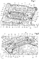
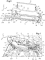
- FIGS. 1 and 2 represent, in two opposite orientations, respectively from front to rear and from rear to front, a support arrangement in a motor vehicle for a battery (referenced 1 on the figure 4 ), intended to supply a small electrical device implanted in the vehicle (not shown) and dedicated to the assistance of the engine.
- a rear body structure 2 of the motor vehicle comprising two side edges or housings 21, 22, extending longitudinally between which can be fixed a plate 23 extending in a substantially transverse longitudinal plane and thus forming a rear floor of the body.
- the rear body floor 23 of the vehicle is further formed of a concave housing 24 constituting a spare wheel receiving tray.
- the bottom wall 25 of the concave housing 24 forming the emergency tire receiving tray and the floor plate of the rear floor 23 are included in respective different planes and normal to the Z axis, once the wheel receiving tray of relief assembled at the rear floor of the body.
- the support arrangement for the battery 1 comprises a substantially plane elongate support member 3 extending transversely to the rear body floor 23, and fixed directly to the back floor plate 23 in a housing. region of the latter located immediately in front and above the concave housing 24 for receiving spare wheel.
- the support member 3 is adapted to extend transversely on the rear floor 23, so as to be located at the rear of a row of at least one seat back of a passenger seat rear of the vehicle and the front of the concave housing 24 for receiving the spare wheel.
- the support element 3 is preferably made of a sheet metal part, substantially in the form of a quadrilateral, obtained for example by stamping.
- the support element 3 mainly comprises a substantially central reception zone 31 intended to receive and hold the battery 1 on the support element 3 when the support element 3 is fixed on the rear floor 23
- the battery receiving zone 31 of the support element 3 is equipped with holding means 32 for holding the battery on the receiving zone 31, for example in the form of fixing pins s'. extending substantially vertically upwardly from a surface of the receiving zone 31 and intended to be inserted into corresponding mounting apertures of the battery when the latter is mounted on the battery receiving zone 31 of the support element 3.
- the battery receiving zone 31 may be partially perforated, for example by means of a substantially rectangular opening made in the area receiving battery, as illustrated in the figures, so as to optimize the mass of the support member 3, without deteriorating its mechanical strength.
- the support element 3 furthermore comprises lateral portions 33, 34 situated respectively on either side of the battery receiving zone 31, along the longitudinal axis of the support element 3 (coinciding with the axis cross section of the vehicle when the support element is attached to the rear floor of the body).
- These lateral parts 33, 34 of the support element 3 are provided with fixing points 330, 340 intended to be fixed to the rear floor of the body 23, so as to allow the fixing of the support element 3 directly on the floor 23.
- rear body 23 distributed on the other side portion 34, located opposite the first side portion 33 relative to the battery receiving zone 31.
- attachment points arranged at the side portions of the element of support 3 allow attachment along the vertical axis of the support element to the rear floor of the body, for example by means of fixing screws cooperating with fastening structures corresponding age on the rear floor of the body.
- the attachment points arranged at the side portions of the support member are distributed so as to allow attachment to and / or in the immediate vicinity of the lateral edges of the rear floor of the body.
- the lateral parts 33, 34 of the support element 3 furthermore comprise positioning means 331, 341 intended to enable the support element 3 to be positioned and consequently the battery mounted on it, relative to the rear body floor 23 and in particular to allow its positioning relative to the transverse longitudinal plane of the rear body floor 23.
- these positioning means comprise a positioning pin 331, 341 respectively arranged on each of the two lateral parts 33, 34. These pieces positioned in a direction substantially normal to the plane of the support member 3 (substantially along the vertical axis) and are intended to pass through a corresponding orifice formed on the rear body floor 23 when the support member is fixed to the rear floor of the body.
- the support element 3 for the battery is designed to integrate functions other than that for the implantation and maintenance of the battery at the rear floor level of the vehicle body, above and to the front of the spare wheel tray.
- the support element 3 comprises fixing means 35 adapted to fix a motor-fan unit on the support element 3.
- a motor-fan unit is indeed necessary for cooling 1.
- the air flow necessary for the cooling of the battery 1 is provided by means of a suction duct 41 for sucking air into the passenger compartment of the vehicle, the air then traveling through the battery 1 to cool, then flows through a conduit 42 to a suction pump 43, before emerging through an exhaust pipe 44 disposed downstream of the pump 43.
- the fixing means 35 of the motor-fan unit on the support member 3 are arranged according to the exemplary embodiment at the side portion 33 of the support member 3 and are more particularly adapted to allow the suction pump 43 of the fan motor unit 4 to be fixed to this lateral part 33 of the support member 3.
- the fixing means 35 are for example in the form of fixing lugs extending substantially vertically upwards from a surface of the lateral portion 34 and are intended to be inserted s in corresponding mounting openings of the pump 41 when the latter is mounted on the side portion 34 of the support member 3.
- the support element 3 is furthermore designed to ensure the integration of the baggage stop function in the trunk of the vehicle.
- the support member 3 incorporates a longitudinal load-arresting crossbar 5, fixed on the support member 3, and adapted to extend transversely in the vehicle between the lateral edges of the rear floor 23 when the support member 3 is attached to the rear floor of the body.
- the longitudinal load-arresting cross member 5 is constituted, for example, by a bent tube 51 attached at each of its ends 52, 53 to the support member, in particular to the respective side portions of the support member.
- attachment points 330, 340 of the support element on the rear floor of the body can be used to mechanically connect the ends 52, 53 of the welded tube 51 to the support element.
- a force-recovery leg, 54, 55 extending perpendicularly to the cross-member, respectively, is provided.
- the force recovery legs 54, 55 thus making it possible to take up the forces exerted on the cross member 5 in the longitudinal direction.
- the support element 3 further comprises fastening means 36 adapted to allow the attachment of a battery case (cladding around the battery, not shown).
- the support element 3 also preferably comprises a longitudinal reinforcing bar 6 removably mounted on the support element 3 and adapted to extend transversely substantially facing the battery receiving zone 31, so as to constitute a support for the battery cover at the top of the battery case when the battery case is mounted around the battery on the support element.
- the longitudinal reinforcing bar 6 of the battery casing is mounted at each of its ends, for example by means of fixing screws, on support lugs 56, 57 projecting substantially vertically from the legs. stress recovery 51, 55.
- the support element 3 comprises gripping handles 37, located on either side of the receiving zone 31 of the battery.
- Each of these gripping handles 37 is for example constituted by a curved wire forming a hoop, fixed at each of its ends on the surface of the support member, on each side of the battery receiving zone.
- the gripping handles 37 thus fixed to the support element are adapted to cooperate with a means of assistance mounting for handling and placing the support member on the rear floor of the body.
- a tool in the form of a fork with two horizontal carrying longitudinal members intended to cooperate with the gripping handles 37 arranged on each side of the battery receiving zone of the support element can be used to handle the support element, in particular for lifting and installing or removing the support element.
Landscapes
- Engineering & Computer Science (AREA)
- Chemical & Material Sciences (AREA)
- Combustion & Propulsion (AREA)
- Transportation (AREA)
- Mechanical Engineering (AREA)
- Arrangement Or Mounting Of Propulsion Units For Vehicles (AREA)
- Body Structure For Vehicles (AREA)
- Battery Mounting, Suspending (AREA)
Claims (9)
- Trägeranordnung einer Batterie (1) zur Versorgung einer an Bord eines Hybridkraftfahrzeugs mitgeführten elektrischen Maschine, welche einen hinteren Karosserieboden (23) aufweist, der mit einer konkaven Aufnahme (24) zum Aufnehmen eines Reserverades versehen ist, wobei die Anordnung ein im Wesentlichen ebenes, lang gestrecktes Trägerelement (3) umfasst, das einen Aufnahmebereich (31) für die Batterie aufweist, der mit Mitteln zum Halten (32) der Batterie auf dem Trägerelement versehen ist, wobei das Trägerelement (3) Punkte zur Befestigung (330, 340) des Trägerelements auf dem hinteren Karosserieboden aufweist und sich quer zu dem hinteren Karosserieboden unmittelbar vor und über der konkaven Aufnahme (24) zum Aufnehmen des Reserverades erstreckt, dadurch gekennzeichnet, dass das Trägerelement (3) Handgriffe (37) umfasst, die sich beiderseits des Aufnahmebereichs (31) für die Batterie befinden, wobei die Handgriffe (37) einen in Bügelform gebogenen Draht umfassen, der an dem Trägerelement (3) befestigt ist und dafür ausgelegt ist, mit einem Montagehilfsmittel für die Handhabung und die Anbringung des Trägerelements auf dem hinteren Karosserieboden zusammenzuwirken.
- Trägeranordnung nach Anspruch 1, dadurch gekennzeichnet, dass die Befestigungspunkte an Seitenteilen (33, 34) des Trägerelements (3) angeordnet sind, die sich beiderseits des Aufnahmebereichs (31) für die Batterie entlang der Längsachse des Trägerelements (3) befinden.
- Trägeranordnung nach Anspruch 2, dadurch gekennzeichnet, dass die Seitenteile (33, 34) des Trägerelements Mittel zur Positionierung (331, 341) des Trägerelements (3) in Bezug auf den hinteren Karosserieboden (23), insbesondere in Bezug auf eine in Längs- und Querrichtung verlaufende Ebene des hinteren Karosseriebodens, umfassen.
- Trägeranordnung nach Anspruch 3, dadurch gekennzeichnet, dass die Mittel zur Positionierung (331, 341) wenigstens einen Positionierstift umfassen, der sich in einer Richtung erstreckt, die zur Ebene des Trägerelements im Wesentlichen senkrecht ist, und geeignet ist, eine entsprechende Öffnung zu durchqueren, die in dem hinteren Karosserieboden ausgebildet ist.
- Anordnung nach einem der vorhergehenden Ansprüche, dadurch gekennzeichnet, dass das Trägerelement (3) Mittel zur Befestigung (36) eines Batteriegehäuses umfasst, und dadurch, dass das Trägerelement eine längs angeordnete Verstärkungsstange (6) umfasst, die lösbar an dem Trägerelement (3) angebracht ist und dafür ausgelegt ist, sich gegenüber dem Batterieaufnahmebereich (31) zu erstrecken, um so eine Abstützung für das Batteriegehäuse im oberen Teil des Batteriegehäuses zu bilden.
- Anordnung nach einem der vorhergehenden Ansprüche, dadurch gekennzeichnet, dass das Trägerelement (3) eine Längstraverse zur Ladungssicherung (5) umfasst, die dafür ausgelegt ist, sich quer im Fahrzeug zwischen den Seitenrändern des hinteren Karosseriebodens zu erstrecken.
- Anordnung nach Anspruch 6, dadurch gekennzeichnet, dass die Längstraverse zur Ladungssicherung (5) ein gebogenes Rohr (51) umfasst, das an jedem seiner Enden (52, 53) an dem Trägerelement (3) befestigt ist.
- Anordnung nach einem der Ansprüche 6 oder 7, dadurch gekennzeichnet, dass sie einen Kraftaufnahmeschenkel (54, 55) in der Nähe jedes der Enden der Längstraverse zur Ladungssicherung (5) aufweist, um diese Traverse und das Trägerelement (3) beiderseits des Aufnahmebereichs (31) für die Batterie zu verbinden.
- Anordnung nach einem der vorhergehenden Ansprüche, dadurch gekennzeichnet, dass sie Mittel zur Befestigung einer Gebläseeinheit an einem Seitenteil des Trägerelements umfasst.
Applications Claiming Priority (2)
| Application Number | Priority Date | Filing Date | Title |
|---|---|---|---|
| FR1555635A FR3037539B1 (fr) | 2015-06-19 | 2015-06-19 | Agencement de support de batterie pour vehicule hybride. |
| PCT/FR2016/051334 WO2016203130A1 (fr) | 2015-06-19 | 2016-06-03 | Agencement de support de batterie pour véhicule hybride |
Publications (2)
| Publication Number | Publication Date |
|---|---|
| EP3310604A1 EP3310604A1 (de) | 2018-04-25 |
| EP3310604B1 true EP3310604B1 (de) | 2019-08-07 |
Family
ID=54145840
Family Applications (1)
| Application Number | Title | Priority Date | Filing Date |
|---|---|---|---|
| EP16739199.4A Active EP3310604B1 (de) | 2015-06-19 | 2016-06-03 | Batterieträgeranordnung für ein hybridfahrzeug |
Country Status (5)
| Country | Link |
|---|---|
| EP (1) | EP3310604B1 (de) |
| JP (1) | JP6722704B2 (de) |
| CN (1) | CN107848387B (de) |
| FR (1) | FR3037539B1 (de) |
| WO (1) | WO2016203130A1 (de) |
Families Citing this family (13)
| Publication number | Priority date | Publication date | Assignee | Title |
|---|---|---|---|---|
| US10632857B2 (en) | 2016-08-17 | 2020-04-28 | Shape Corp. | Battery support and protection structure for a vehicle |
| CN110383526A (zh) | 2017-01-04 | 2019-10-25 | 形状集团 | 节点模块化的车辆电池托盘结构 |
| US10483510B2 (en) | 2017-05-16 | 2019-11-19 | Shape Corp. | Polarized battery tray for a vehicle |
| US10886513B2 (en) | 2017-05-16 | 2021-01-05 | Shape Corp. | Vehicle battery tray having tub-based integration |
| WO2018213383A1 (en) | 2017-05-16 | 2018-11-22 | Shape Corp. | Vehicle battery tray with integrated battery retention and support features |
| US12347879B2 (en) | 2017-09-13 | 2025-07-01 | Shape Corp. | Vehicle battery tray with tubular peripheral wall |
| CN111108015A (zh) | 2017-09-13 | 2020-05-05 | 形状集团 | 具有管状外围壁的车辆电池托盘 |
| WO2019071013A1 (en) | 2017-10-04 | 2019-04-11 | Shape Corp. | BATTERY SUPPORT BOTTOM ASSEMBLY FOR ELECTRIC VEHICLES |
| EP3759761B1 (de) | 2018-03-01 | 2026-04-08 | Shape Corp. | In fahrzeugbatteriefach integriertes kühlsystem |
| US11688910B2 (en) | 2018-03-15 | 2023-06-27 | Shape Corp. | Vehicle battery tray having tub-based component |
| FR3086893B1 (fr) * | 2018-10-03 | 2020-11-20 | Renault Sas | Dispositif d'absorption d'energie cinetique pour la protection contre les chocs d'une batterie pour vehicule automobile |
| FR3093031B1 (fr) * | 2019-02-27 | 2021-02-19 | Psa Automobiles Sa | Platine d’adaptation d’une batterie sur un organe de support |
| FR3104123A1 (fr) * | 2019-12-06 | 2021-06-11 | Renault S.A.S | Plancher avec protection de batterie sous siège avant. |
Family Cites Families (10)
| Publication number | Priority date | Publication date | Assignee | Title |
|---|---|---|---|---|
| JP4221998B2 (ja) * | 2002-10-28 | 2009-02-12 | スズキ株式会社 | 車両の電気機器固定構造 |
| JP4687015B2 (ja) * | 2004-06-23 | 2011-05-25 | トヨタ自動車株式会社 | 電源装置 |
| FR2934927B1 (fr) * | 2008-08-08 | 2011-06-03 | Renault Sas | Stucture de support de batterie pour vehicule automobile |
| JP5375727B2 (ja) * | 2010-04-13 | 2013-12-25 | トヨタ自動車株式会社 | 蓄電パックの車両搭載構造 |
| CN201890126U (zh) * | 2010-11-02 | 2011-07-06 | 上海汽车集团股份有限公司 | 动力箱支架 |
| JP5729207B2 (ja) * | 2011-08-09 | 2015-06-03 | マツダ株式会社 | 車両の電源装置支持構造 |
| JP6155645B2 (ja) * | 2013-01-09 | 2017-07-05 | スズキ株式会社 | 車両用バッテリパック支持構造 |
| DE102013106297B4 (de) * | 2013-06-18 | 2025-08-14 | Dr. Ing. H.C. F. Porsche Aktiengesellschaft | Karosserieanordnung mit einer Schutzanordnung für sicherheitsrelevante Teile im Kraftfahrzeugbereich |
| WO2015019742A1 (ja) * | 2013-08-07 | 2015-02-12 | 日産自動車株式会社 | バッテリ車体取り付け構造 |
| JP6112219B2 (ja) * | 2013-10-28 | 2017-04-12 | 日産自動車株式会社 | バッテリー保護構造 |
-
2015
- 2015-06-19 FR FR1555635A patent/FR3037539B1/fr not_active Expired - Fee Related
-
2016
- 2016-06-03 WO PCT/FR2016/051334 patent/WO2016203130A1/fr not_active Ceased
- 2016-06-03 CN CN201680042623.2A patent/CN107848387B/zh active Active
- 2016-06-03 EP EP16739199.4A patent/EP3310604B1/de active Active
- 2016-06-03 JP JP2017565098A patent/JP6722704B2/ja active Active
Non-Patent Citations (1)
| Title |
|---|
| None * |
Also Published As
| Publication number | Publication date |
|---|---|
| JP2018517615A (ja) | 2018-07-05 |
| CN107848387B (zh) | 2021-02-02 |
| FR3037539B1 (fr) | 2020-05-29 |
| CN107848387A (zh) | 2018-03-27 |
| WO2016203130A1 (fr) | 2016-12-22 |
| JP6722704B2 (ja) | 2020-07-15 |
| FR3037539A1 (fr) | 2016-12-23 |
| EP3310604A1 (de) | 2018-04-25 |
Similar Documents
| Publication | Publication Date | Title |
|---|---|---|
| EP3310604B1 (de) | Batterieträgeranordnung für ein hybridfahrzeug | |
| EP3359405B1 (de) | Batteriehalterungsanordnung für hybridfahrzeug | |
| EP3097001B1 (de) | Kraftfahrzeuggestell mit zwei verstärkten seitenelementen | |
| BE1026121B1 (fr) | Bicyclette electrique | |
| EP2598394A2 (de) | Kraftfahrzeug-chassis | |
| WO2021038157A1 (fr) | Vehicule hybride ou electrique avec dispositif de renforcement de sa structure de bas de caisse | |
| FR2890366A1 (fr) | Plancher central de vehicule automobile | |
| EP3720734B1 (de) | Kraftfahrzeug mit sitz mit zugang zu einem batteriehauptschalter | |
| WO2021219300A1 (fr) | Véhicule doté d'une traverse centrale arrière multifonction | |
| EP2934990A1 (de) | Anordnung für eine mechanische basisstruktur eines kraftfahrzeugs mit einem gehäuse mit einer vorrichtung zur steuerung einer sicherung | |
| EP3694769B1 (de) | Struktur des hinteren teils der karosserie eines kraftfahrzeugs | |
| FR2977837A1 (fr) | Berceau pour vehicule automobile electrique ou hybride | |
| FR3138634A1 (fr) | Agencement d'un compartiment moteur d'un véhicule automobile | |
| WO2017042455A1 (fr) | Dispositif electrique incline au-dessus d'un passage de roue de vehicule | |
| FR3067298B1 (fr) | Ensemble pour chassis de vehicule hybride facilitant l'acces a un reservoir | |
| FR3059952A1 (fr) | Siege de vehicule automobile | |
| FR3099742A1 (fr) | Déflecteur à bords longitudinaux à extensions, pour un soubassement de véhicule | |
| FR3160152A1 (fr) | Assemblage assisté d’un soubassement de véhicule automobile | |
| FR3102434A1 (fr) | Véhicule automobile comprenant une batterie, et un système de fixation de la batterie | |
| FR3162717A1 (fr) | Carter pour bloc-batterie de véhicule automobile à propulsion électrique | |
| EP3931016A1 (de) | Platte zur anpassung einer batterie an ein trägerelement | |
| WO2025162839A1 (fr) | Système de fixation pour un composant électronique haute puissance d'un véhicule électrique ou hybride, châssis de véhicule comprenant le système de fixation et véhicule électrique ou hybride comprenant le châssis | |
| FR3137653A1 (fr) | Structure avant de véhicule automobile électrique équipé d’un générateur sonore | |
| FR3149282A1 (fr) | Module de châssis de véhicule automobile et véhicule comprenant un tel module | |
| FR2989656A1 (fr) | Support de prise de charge rapide pour vehicule electrique, notamment automobile. |
Legal Events
| Date | Code | Title | Description |
|---|---|---|---|
| STAA | Information on the status of an ep patent application or granted ep patent |
Free format text: STATUS: THE INTERNATIONAL PUBLICATION HAS BEEN MADE |
|
| PUAI | Public reference made under article 153(3) epc to a published international application that has entered the european phase |
Free format text: ORIGINAL CODE: 0009012 |
|
| STAA | Information on the status of an ep patent application or granted ep patent |
Free format text: STATUS: REQUEST FOR EXAMINATION WAS MADE |
|
| 17P | Request for examination filed |
Effective date: 20180111 |
|
| AK | Designated contracting states |
Kind code of ref document: A1 Designated state(s): AL AT BE BG CH CY CZ DE DK EE ES FI FR GB GR HR HU IE IS IT LI LT LU LV MC MK MT NL NO PL PT RO RS SE SI SK SM TR |
|
| AX | Request for extension of the european patent |
Extension state: BA ME |
|
| DAV | Request for validation of the european patent (deleted) | ||
| DAX | Request for extension of the european patent (deleted) | ||
| GRAP | Despatch of communication of intention to grant a patent |
Free format text: ORIGINAL CODE: EPIDOSNIGR1 |
|
| STAA | Information on the status of an ep patent application or granted ep patent |
Free format text: STATUS: GRANT OF PATENT IS INTENDED |
|
| INTG | Intention to grant announced |
Effective date: 20190219 |
|
| GRAS | Grant fee paid |
Free format text: ORIGINAL CODE: EPIDOSNIGR3 |
|
| GRAA | (expected) grant |
Free format text: ORIGINAL CODE: 0009210 |
|
| STAA | Information on the status of an ep patent application or granted ep patent |
Free format text: STATUS: THE PATENT HAS BEEN GRANTED |
|
| AK | Designated contracting states |
Kind code of ref document: B1 Designated state(s): AL AT BE BG CH CY CZ DE DK EE ES FI FR GB GR HR HU IE IS IT LI LT LU LV MC MK MT NL NO PL PT RO RS SE SI SK SM TR |
|
| REG | Reference to a national code |
Ref country code: GB Ref legal event code: FG4D Free format text: NOT ENGLISH |
|
| REG | Reference to a national code |
Ref country code: CH Ref legal event code: EP Ref country code: AT Ref legal event code: REF Ref document number: 1163287 Country of ref document: AT Kind code of ref document: T Effective date: 20190815 |
|
| REG | Reference to a national code |
Ref country code: IE Ref legal event code: FG4D Free format text: LANGUAGE OF EP DOCUMENT: FRENCH |
|
| REG | Reference to a national code |
Ref country code: DE Ref legal event code: R096 Ref document number: 602016018204 Country of ref document: DE |
|
| REG | Reference to a national code |
Ref country code: NL Ref legal event code: MP Effective date: 20190807 |
|
| REG | Reference to a national code |
Ref country code: LT Ref legal event code: MG4D |
|
| PG25 | Lapsed in a contracting state [announced via postgrant information from national office to epo] |
Ref country code: HR Free format text: LAPSE BECAUSE OF FAILURE TO SUBMIT A TRANSLATION OF THE DESCRIPTION OR TO PAY THE FEE WITHIN THE PRESCRIBED TIME-LIMIT Effective date: 20190807 Ref country code: SE Free format text: LAPSE BECAUSE OF FAILURE TO SUBMIT A TRANSLATION OF THE DESCRIPTION OR TO PAY THE FEE WITHIN THE PRESCRIBED TIME-LIMIT Effective date: 20190807 Ref country code: NO Free format text: LAPSE BECAUSE OF FAILURE TO SUBMIT A TRANSLATION OF THE DESCRIPTION OR TO PAY THE FEE WITHIN THE PRESCRIBED TIME-LIMIT Effective date: 20191107 Ref country code: FI Free format text: LAPSE BECAUSE OF FAILURE TO SUBMIT A TRANSLATION OF THE DESCRIPTION OR TO PAY THE FEE WITHIN THE PRESCRIBED TIME-LIMIT Effective date: 20190807 Ref country code: PT Free format text: LAPSE BECAUSE OF FAILURE TO SUBMIT A TRANSLATION OF THE DESCRIPTION OR TO PAY THE FEE WITHIN THE PRESCRIBED TIME-LIMIT Effective date: 20191209 Ref country code: BG Free format text: LAPSE BECAUSE OF FAILURE TO SUBMIT A TRANSLATION OF THE DESCRIPTION OR TO PAY THE FEE WITHIN THE PRESCRIBED TIME-LIMIT Effective date: 20191107 Ref country code: NL Free format text: LAPSE BECAUSE OF FAILURE TO SUBMIT A TRANSLATION OF THE DESCRIPTION OR TO PAY THE FEE WITHIN THE PRESCRIBED TIME-LIMIT Effective date: 20190807 Ref country code: LT Free format text: LAPSE BECAUSE OF FAILURE TO SUBMIT A TRANSLATION OF THE DESCRIPTION OR TO PAY THE FEE WITHIN THE PRESCRIBED TIME-LIMIT Effective date: 20190807 |
|
| REG | Reference to a national code |
Ref country code: AT Ref legal event code: MK05 Ref document number: 1163287 Country of ref document: AT Kind code of ref document: T Effective date: 20190807 |
|
| PG25 | Lapsed in a contracting state [announced via postgrant information from national office to epo] |
Ref country code: RS Free format text: LAPSE BECAUSE OF FAILURE TO SUBMIT A TRANSLATION OF THE DESCRIPTION OR TO PAY THE FEE WITHIN THE PRESCRIBED TIME-LIMIT Effective date: 20190807 Ref country code: IS Free format text: LAPSE BECAUSE OF FAILURE TO SUBMIT A TRANSLATION OF THE DESCRIPTION OR TO PAY THE FEE WITHIN THE PRESCRIBED TIME-LIMIT Effective date: 20191207 Ref country code: LV Free format text: LAPSE BECAUSE OF FAILURE TO SUBMIT A TRANSLATION OF THE DESCRIPTION OR TO PAY THE FEE WITHIN THE PRESCRIBED TIME-LIMIT Effective date: 20190807 Ref country code: GR Free format text: LAPSE BECAUSE OF FAILURE TO SUBMIT A TRANSLATION OF THE DESCRIPTION OR TO PAY THE FEE WITHIN THE PRESCRIBED TIME-LIMIT Effective date: 20191108 Ref country code: AL Free format text: LAPSE BECAUSE OF FAILURE TO SUBMIT A TRANSLATION OF THE DESCRIPTION OR TO PAY THE FEE WITHIN THE PRESCRIBED TIME-LIMIT Effective date: 20190807 Ref country code: ES Free format text: LAPSE BECAUSE OF FAILURE TO SUBMIT A TRANSLATION OF THE DESCRIPTION OR TO PAY THE FEE WITHIN THE PRESCRIBED TIME-LIMIT Effective date: 20190807 |
|
| PG25 | Lapsed in a contracting state [announced via postgrant information from national office to epo] |
Ref country code: TR Free format text: LAPSE BECAUSE OF FAILURE TO SUBMIT A TRANSLATION OF THE DESCRIPTION OR TO PAY THE FEE WITHIN THE PRESCRIBED TIME-LIMIT Effective date: 20190807 |
|
| PG25 | Lapsed in a contracting state [announced via postgrant information from national office to epo] |
Ref country code: DK Free format text: LAPSE BECAUSE OF FAILURE TO SUBMIT A TRANSLATION OF THE DESCRIPTION OR TO PAY THE FEE WITHIN THE PRESCRIBED TIME-LIMIT Effective date: 20190807 Ref country code: PL Free format text: LAPSE BECAUSE OF FAILURE TO SUBMIT A TRANSLATION OF THE DESCRIPTION OR TO PAY THE FEE WITHIN THE PRESCRIBED TIME-LIMIT Effective date: 20190807 Ref country code: RO Free format text: LAPSE BECAUSE OF FAILURE TO SUBMIT A TRANSLATION OF THE DESCRIPTION OR TO PAY THE FEE WITHIN THE PRESCRIBED TIME-LIMIT Effective date: 20190807 Ref country code: EE Free format text: LAPSE BECAUSE OF FAILURE TO SUBMIT A TRANSLATION OF THE DESCRIPTION OR TO PAY THE FEE WITHIN THE PRESCRIBED TIME-LIMIT Effective date: 20190807 Ref country code: IT Free format text: LAPSE BECAUSE OF FAILURE TO SUBMIT A TRANSLATION OF THE DESCRIPTION OR TO PAY THE FEE WITHIN THE PRESCRIBED TIME-LIMIT Effective date: 20190807 Ref country code: AT Free format text: LAPSE BECAUSE OF FAILURE TO SUBMIT A TRANSLATION OF THE DESCRIPTION OR TO PAY THE FEE WITHIN THE PRESCRIBED TIME-LIMIT Effective date: 20190807 |
|
| PG25 | Lapsed in a contracting state [announced via postgrant information from national office to epo] |
Ref country code: IS Free format text: LAPSE BECAUSE OF FAILURE TO SUBMIT A TRANSLATION OF THE DESCRIPTION OR TO PAY THE FEE WITHIN THE PRESCRIBED TIME-LIMIT Effective date: 20200224 Ref country code: SM Free format text: LAPSE BECAUSE OF FAILURE TO SUBMIT A TRANSLATION OF THE DESCRIPTION OR TO PAY THE FEE WITHIN THE PRESCRIBED TIME-LIMIT Effective date: 20190807 Ref country code: CZ Free format text: LAPSE BECAUSE OF FAILURE TO SUBMIT A TRANSLATION OF THE DESCRIPTION OR TO PAY THE FEE WITHIN THE PRESCRIBED TIME-LIMIT Effective date: 20190807 Ref country code: SK Free format text: LAPSE BECAUSE OF FAILURE TO SUBMIT A TRANSLATION OF THE DESCRIPTION OR TO PAY THE FEE WITHIN THE PRESCRIBED TIME-LIMIT Effective date: 20190807 |
|
| REG | Reference to a national code |
Ref country code: DE Ref legal event code: R097 Ref document number: 602016018204 Country of ref document: DE |
|
| PLBE | No opposition filed within time limit |
Free format text: ORIGINAL CODE: 0009261 |
|
| STAA | Information on the status of an ep patent application or granted ep patent |
Free format text: STATUS: NO OPPOSITION FILED WITHIN TIME LIMIT |
|
| PG2D | Information on lapse in contracting state deleted |
Ref country code: IS |
|
| 26N | No opposition filed |
Effective date: 20200603 |
|
| PG25 | Lapsed in a contracting state [announced via postgrant information from national office to epo] |
Ref country code: SI Free format text: LAPSE BECAUSE OF FAILURE TO SUBMIT A TRANSLATION OF THE DESCRIPTION OR TO PAY THE FEE WITHIN THE PRESCRIBED TIME-LIMIT Effective date: 20190807 |
|
| PG25 | Lapsed in a contracting state [announced via postgrant information from national office to epo] |
Ref country code: MC Free format text: LAPSE BECAUSE OF FAILURE TO SUBMIT A TRANSLATION OF THE DESCRIPTION OR TO PAY THE FEE WITHIN THE PRESCRIBED TIME-LIMIT Effective date: 20190807 |
|
| REG | Reference to a national code |
Ref country code: CH Ref legal event code: PL |
|
| PG25 | Lapsed in a contracting state [announced via postgrant information from national office to epo] |
Ref country code: LU Free format text: LAPSE BECAUSE OF NON-PAYMENT OF DUE FEES Effective date: 20200603 |
|
| REG | Reference to a national code |
Ref country code: BE Ref legal event code: MM Effective date: 20200630 |
|
| PG25 | Lapsed in a contracting state [announced via postgrant information from national office to epo] |
Ref country code: IE Free format text: LAPSE BECAUSE OF NON-PAYMENT OF DUE FEES Effective date: 20200603 Ref country code: CH Free format text: LAPSE BECAUSE OF NON-PAYMENT OF DUE FEES Effective date: 20200630 Ref country code: LI Free format text: LAPSE BECAUSE OF NON-PAYMENT OF DUE FEES Effective date: 20200630 |
|
| PG25 | Lapsed in a contracting state [announced via postgrant information from national office to epo] |
Ref country code: BE Free format text: LAPSE BECAUSE OF NON-PAYMENT OF DUE FEES Effective date: 20200630 |
|
| PG25 | Lapsed in a contracting state [announced via postgrant information from national office to epo] |
Ref country code: MT Free format text: LAPSE BECAUSE OF FAILURE TO SUBMIT A TRANSLATION OF THE DESCRIPTION OR TO PAY THE FEE WITHIN THE PRESCRIBED TIME-LIMIT Effective date: 20190807 Ref country code: CY Free format text: LAPSE BECAUSE OF FAILURE TO SUBMIT A TRANSLATION OF THE DESCRIPTION OR TO PAY THE FEE WITHIN THE PRESCRIBED TIME-LIMIT Effective date: 20190807 |
|
| PG25 | Lapsed in a contracting state [announced via postgrant information from national office to epo] |
Ref country code: MK Free format text: LAPSE BECAUSE OF FAILURE TO SUBMIT A TRANSLATION OF THE DESCRIPTION OR TO PAY THE FEE WITHIN THE PRESCRIBED TIME-LIMIT Effective date: 20190807 |
|
| P01 | Opt-out of the competence of the unified patent court (upc) registered |
Effective date: 20230608 |
|
| PGFP | Annual fee paid to national office [announced via postgrant information from national office to epo] |
Ref country code: DE Payment date: 20250618 Year of fee payment: 10 |
|
| PGFP | Annual fee paid to national office [announced via postgrant information from national office to epo] |
Ref country code: GB Payment date: 20250618 Year of fee payment: 10 |
|
| PGFP | Annual fee paid to national office [announced via postgrant information from national office to epo] |
Ref country code: FR Payment date: 20250625 Year of fee payment: 10 |