EP3310997B1 - Caractérisation d'un dysfonctionnement de forage tourbillonnaire - Google Patents
Caractérisation d'un dysfonctionnement de forage tourbillonnaire Download PDFInfo
- Publication number
- EP3310997B1 EP3310997B1 EP16812555.7A EP16812555A EP3310997B1 EP 3310997 B1 EP3310997 B1 EP 3310997B1 EP 16812555 A EP16812555 A EP 16812555A EP 3310997 B1 EP3310997 B1 EP 3310997B1
- Authority
- EP
- European Patent Office
- Prior art keywords
- whirl
- drill string
- centers
- rotation
- ellipse
- Prior art date
- Legal status (The legal status is an assumption and is not a legal conclusion. Google has not performed a legal analysis and makes no representation as to the accuracy of the status listed.)
- Active
Links
Images




Classifications
-
- E—FIXED CONSTRUCTIONS
- E21—EARTH OR ROCK DRILLING; MINING
- E21B—EARTH OR ROCK DRILLING; OBTAINING OIL, GAS, WATER, SOLUBLE OR MELTABLE MATERIALS OR A SLURRY OF MINERALS FROM WELLS
- E21B44/00—Automatic control systems specially adapted for drilling operations, i.e. self-operating systems which function to carry out or modify a drilling operation without intervention of a human operator, e.g. computer-controlled drilling systems; Systems specially adapted for monitoring a plurality of drilling variables or conditions
Definitions
- Embodiments of the invention relate to systems and methods for determining whirl attributes of a rotating drill string, which may be used in hydrocarbon drilling operations.
- Hydrocarbon reservoirs are developed with drilling operations using a drill bit associated with a drill string rotated from the surface or using a downhole motor, or both using a downhole motor and also rotating the string from the surface.
- a bottom hole assembly (BHA) at the end of the drill string may include components such as drill collars, stabilizers, drilling motors and logging tools, and measuring tools.
- a BHA is also capable of telemetering various drilling and geological parameters to the surface facilities.
- Resistance encountered by the drill string in a wellbore during drilling causes significant wear on the drill string, especially the drill bit and the BHA. Understanding how the geometry of the wellbore affects resistance on the drill string and the BHA and managing the dynamic conditions that lead potentially to failure of downhole equipment is important for enhancing efficiency and minimizing costs for drilling wells.
- Various conditions referred to as drilling dysfunctions that may lead to component failure include excessive torque, shocks, bit bounce, induced vibrations, bit whirl, stick-slip, among others. These conditions must be rapidly detected so that mitigation efforts are undertaken as quickly as possible, since some dysfunctions can quickly lead to tool failures.
- Whirl refers to a lateral vibration where the rotational axis of the bit does not align with the center of the borehole, and the bit center performs additional rotations around the borehole.
- Three distinct whirl forms include: (1) backward whirl where the drill string rotates clockwise and the center of the drill string rotates counter-clockwise around the borehole; (2) forward whirl where both drill string and drill-pipe center rotate clockwise but with different rotational speeds; and (3) chaotic whirl where the drill-pipe center does not follow a particular direction but moves in a random and highly unstable fashion.
- Tri-axial accelerometers used in the drilling industry measure three orthogonal accelerations related to shock and vibration during drilling operations.
- the magnitudes of the acceleration data provide a qualitative evaluation of the extent of the drill string vibration.
- the acceleration data combined with other information may produce a qualitative drilling risk index.
- whirl frequency in combination with acceleration data, in turn, produces whirl magnitude. Therefore, a need exists for systems and methods to provide reliable determinations of drill string whirl attributes, such as magnitude, orientation and velocity.
- Embodiments of the invention relate to methods and systems for outputting at least one drill string whirl attribute, such as magnitude, orientation, velocity and type, without requiring determination of whirl frequency.
- Transforming acceleration data into drill string motions provides a path of one point along the drill string. Fitting these motions throughout one complete revolution of the drill string to a revolution ellipse, for example, provides revolution ellipse centers defining centers of rotation for each revolution fitted.
- a whirl ellipse for example, derives from another fitting using a plurality of the revolution ellipse centers.
- Coefficients from the whirl ellipse and/or vector direction of the centers provide at least one whirl attribute for output. While described with respect to drilling, the output may apply to other rotating equipment problems as well and may be used in any application for proactive detection of temporal events in automated systems to aid in avoiding failures.
- a computer readable medium (or computer-readable storage medium/media) stores computer data, which data can include computer program code (or computer-executable instructions) that is executable by a computer, in machine readable form.
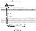
- FIG. 1 illustrates surface drilling rig facilities 101 used to recover hydrocarbons from a subterranean formation with a well bore 102.
- the surface drilling rig facilities 101 include a drilling rig and associated control and supporting facilities including processor 103, which may include data aggregation and data processing infrastructure described further herein as well as drill rig control facilities.
- the well bore 102 includes a drill string comprising a bottom hole assembly (BHA) that may include a mud motor 112, an adjustable bent housing or 'BHA Dynamic Sub' 114 containing various sensors and electronic components and a drill bit 116.
- BHA bottom hole assembly
- the BHA Dynamic Sub 114 acquires data including tri-axial acceleration data from respective sensors. Any data acquired with the BHA Dynamic Sub 114 may be transmitted to the drilling rig facilities 101 through drill string telemetry or through mud-pulse telemetry as time series data.
- the drill string may also contain associated sensors, for example mid-string dynamic subs 110, acquiring data utilized in some embodiments for determining drill string whirl attributes, and these instrumented subs can also send signals representing these measurements up the drill string where they are recorded on or near the drilling rig.
- FIG. 2A provides a vector representation 200 of circular drill string positions.
- continuous drill string position determination uses three-orthogonal accelerations.
- P (x, y, z, t) is a position vector in a global stationary coordinate frame referenced at the center of the drill string
- a (x, y, z, t) is an acceleration vector in a global stationary coordinate frame referenced at the center of the drill string
- t is the travel time of the drill string motion.
- the drill string positions can be continuously determined using equation 3.
- D(P) is a damping function such that D(P) increases significantly when
- D(p) exp P 2 R p 2 ⁇ 1
- a search for the correct drill string position that satisfies the acceleration data utilizes an iterative search on P to find the P that minimizes the objective function J(P) of equation 4. While one implementation uses a linearized quasi-Newton method to perform the iterative search, other exemplary suitable search methods include steepest descent or Monte Carlo.
- the recorded acceleration data include both the earth's gravitational and centripetal accelerations. Both accelerations should be accounted for before applying equation 3. Difficulty in obtaining exact locations and orientations of the downhole tri-axial accelerometers at a particular instance of time because of buckling and bending of the drill string make estimates for the exact gravitational and centripetal accelerations as a position of drilling depth challenging.
- a simple, but effective method to correct both gravitational and centripetal accelerations includes approximating both corrections by a local running mean of the acceleration data. After removing the local running mean, the acceleration data yield the measurements due to the vibration only.
- FIG. 2B illustrates the transformation of acceleration data from a local moving coordinate frame to a global stationary coordinate frame.
- Equation 3 also requires the acceleration data to be in a stationary coordinate frame.
- the tri-axial accelerometers mount on the drill string.
- the tri-axial accelerometers rotate with the drill string.
- the recorded acceleration data is in a local rotating coordinate frame. It is necessary to transform from the local rotating coordinate frame to a global stationary coordinate frame.
- the tri-axial accelerometers are rigidly mounted on the drill string, the axial acceleration in the local rotating coordinate frame is equivalent to a stationary coordinate frame.
- the coordinate transformation reduces to a 2-D rotation in X-Y plane.
- ax t ay t az t cos ⁇ ⁇ sin ⁇ 0 sin ⁇ cos ⁇ 0 0 0 1 ar t at t az t
- ar, at and az are radial, tangential and axial accelerations in a local moving coordinate frame
- ax, ay and az are the corresponding accelerations in a global stationary coordinate frame
- ⁇ is the rotational angle ( See FIG. 2B ).
- a conventional approach to estimate the rotational angle ⁇ uses the vector dot product between acceleration vectors ax and ar.
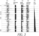
- FIG. 3 shows input data including data channel 1 - axial vibration 301, representing axial acceleration; data channel 2 - down-hole rotations per minute (RPM) 302; data channel 3 - radial vibration 303, representing the polar coordinates of radial acceleration; and data channel 4 - tangential vibration 304, representing the polar coordinates of tangential acceleration.
- Data channel 5 presents measured hole depth 305.
- transforming tri-axial accelerations into drill string motions includes the following three steps: (1) approximating the gravitational and centripetal accelerations by a local running mean of the acceleration data and removing the local running mean to yield the acceleration measurements due to the vibration only, (2) transforming the corrected acceleration data from a local rotating coordinate frame to a global stationary coordinate frame using equation 6, and (3) mapping the acceleration data into continuous drill string positions via equation 3.
- transforming tri-axial accelerations into drill string motions includes an iterative search on P to find the P that minimizes the objective function J(P) of equation 4 and that is then mapped into continuous drill string positions.
- FIG. 4 illustrates the drill string motions computed from this numerical optimization, as shown by dots 400, and fitted to a revolution ellipse 402, as shown by a line, for a complete revolution of the drill string inside the wellbore 406.
- the least-squares algorithm fits the drill string motions within a complete revolution to derive the coefficients of A, B, C, D, E and F.
- the coefficients of the ellipse in turn, yield the major and minor axes, rotational angle, and center 404 of the revolution ellipse 402.
- FIG. 5 shows five revolution ellipses 502 fitted from data with each of the revolution ellipses 502 having centers 504A-E shown by dots, which may also be fitted by a least-squares algorithm to a whirl ellipse 520 shown by a dashed line.
- deriving the whirl ellipse 520 may utilize at least five of the centers 504A-E.
- the whirl ellipse 520 updates with continuous fitting to sensed data of another revolution of the drill string replacing oldest sensed data used in prior determinations of the whirl ellipse 520 and thus may provide real-time results.
- the whirl ellipse 520 provides whirl magnitude, orientation and velocity.
- Whirl orientation corresponds to rotational angle of the whirl ellipse 520 obtained from the coefficients set forth in the ellipse equations 8 and 9.
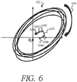
- FIG. 6 depicts the centers of revolution ellipses 504A-E shown in FIG. 5 with vector direction 620 illustrated to determine whirl direction shown by example opposite to drill string rotation 604.
- the vector direction 620 thereby identifies type of whirl motion, which is depicted as backward whirl.
- the vector direction 620 takes account of succession in time given a first center of revolution ellipse 504A, a second center of revolution ellipse 504B, a third center of revolution ellipse 504C, a fourth center of revolution ellipse 504D and a fifth center of revolution ellipse 504E correspond to respective earlier through later drill string revolutions.
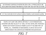
- FIG. 7 depicts an exemplary flow chart of a method for the whirl determination as described herein with respect to FIGS. 1-6 .
- the sensors on the drill string e.g., at the mid-string dynamic subs 110 or the BHA Dynamic Sub 114 ) acquire acceleration data sent to the processor 103.
- the processor determines centers of rotation on the drill string based on the acceleration sensed per revolution for each of the centers. Such determination may include transforming the acceleration data into drill string motions and fitting the motions per revolution to respective ellipses, which centers estimate the centers of single rotations on the drill string.
- a whirl determination step 701 includes fitting the centers to a closed curved shape, such as another ellipse referred to herein as a whirl ellipse, and outputting at least one whirl attribute upon determining magnitude, orientation, velocity and/or type of drill string whirl. Determining the magnitude, orientation and/or velocity of the drill string whirl utilizes coefficients derived from the whirl ellipse. Further, determining type of whirl, e.g., forward or backward, relies on vector direction of the centers determined in succession.
- the processor may output to a user the whirl attribute on a display of the processor 103 or other remote location for monitoring drilling performance.
- the output of the whirl attribute results in automatic or user controlled stopping and restarting of drilling, adjusting weight on bit, changing drill string rotation rate, drill bit replacement and/or adjusting drill string stiffness.
- Such mitigation efforts may continue based on feedback from the output of the whirl attribute until the output of the whirl attribute reaches an acceptable level to avoid or limit tool failures.
Landscapes
- Engineering & Computer Science (AREA)
- Geology (AREA)
- Life Sciences & Earth Sciences (AREA)
- Mining & Mineral Resources (AREA)
- Physics & Mathematics (AREA)
- Environmental & Geological Engineering (AREA)
- Fluid Mechanics (AREA)
- General Life Sciences & Earth Sciences (AREA)
- Geochemistry & Mineralogy (AREA)
- Earth Drilling (AREA)
- Drilling And Boring (AREA)
- Mechanical Engineering (AREA)
- General Physics & Mathematics (AREA)
Claims (2)
- Procédé de détermination d'un attribut de tourbillon d'un train de tiges de forage en utilisant une accélération détectée, caractérisé en ce que le procédé comprend les étapes consistant à :estimer des centres de rotation (404, 504) sur le train de tiges de forage sur la base d'une accélération détectée par révolution pour chacun des centres de rotation (404, 504) étant estimés ; etdéterminer l'attribut de tourbillon à partir d'informations fournies par les centres de rotation (404, 504) pour délivrer en sortie l'attribut de tourbillon sélectionné parmi au moins l'un d'une amplitude, d'une orientation, d'une vitesse et d'un type de tourbillon,dans lequel l'estimation des centres de rotation (404, 504) inclut la transformation de l'accélération détectée en mouvements de train de tiges de forage et l'ajustement des mouvements par révolution à des ellipses de révolution respectives (402, 502) ayant des positions centrales elliptiques définissant au moins cinq des centres de rotation (404, 504) ; etla détermination de l'attribut de tourbillon inclut l'ajustement des centres de rotation (404, 504) à une ellipse de tourbillon (520) avec des coefficients de l'ellipse de tourbillon (520) utilisés pour fournir l'amplitude, l'orientation et la vitesse du tourbillon.
- Système pour déterminer un attribut de tourbillon d'un train de tiges de forage, comprenant :un appareil de forage couplé au train de tiges de forage s'étendant dans un trou de forage ;un capteur (110) disposé sur le train de tiges de forage pour détecter une accélération ; etun processeur (103) couplé pour recevoir des données en provenance du capteur (110) ;caractérisé en ce que le processeur (103) est configuré pour déterminer l'attribut de tourbillon en estimant des centres de rotation (404, 504) sur le train de tiges de forage sur la base des données par révolution pour chacun des centres de rotation (404, 504) étant estimés et en déduisant des centres de rotation (404, 504) au moins l'un d'une amplitude, d'une orientation, d'une vitesse et d'un type de tourbillon,dans lequel le processeur (103) est configuré pour transformer l'accélération détectée en mouvements de train de tiges de forage et pour ajuster les mouvements par révolution aux ellipses de révolution respectives (402, 502) ayant des positions centrales elliptiques définissant au moins cinq des centres de rotation (404, 504) et pour ajuster les centres à une ellipse de tourbillon (520) avec des coefficients de l'ellipse de tourbillon (520) appliqués pour déduite l'amplitude, l'orientation et la vitesse du tourbillon.
Applications Claiming Priority (3)
| Application Number | Priority Date | Filing Date | Title |
|---|---|---|---|
| US201562181559P | 2015-06-18 | 2015-06-18 | |
| PCT/US2016/038167 WO2016205706A1 (fr) | 2015-06-18 | 2016-06-17 | Caractérisation d'un dysfonctionnement de forage tourbillonnaire |
| US15/186,012 US9926776B2 (en) | 2015-06-18 | 2016-06-17 | Characterization of whirl drilling dysfunction |
Publications (3)
| Publication Number | Publication Date |
|---|---|
| EP3310997A1 EP3310997A1 (fr) | 2018-04-25 |
| EP3310997A4 EP3310997A4 (fr) | 2018-06-27 |
| EP3310997B1 true EP3310997B1 (fr) | 2019-08-07 |
Family
ID=57546488
Family Applications (1)
| Application Number | Title | Priority Date | Filing Date |
|---|---|---|---|
| EP16812555.7A Active EP3310997B1 (fr) | 2015-06-18 | 2016-06-17 | Caractérisation d'un dysfonctionnement de forage tourbillonnaire |
Country Status (8)
| Country | Link |
|---|---|
| US (1) | US9926776B2 (fr) |
| EP (1) | EP3310997B1 (fr) |
| CN (1) | CN108026765B (fr) |
| AU (1) | AU2016278985B2 (fr) |
| CA (1) | CA2988794C (fr) |
| CO (1) | CO2017012970A2 (fr) |
| MY (1) | MY184245A (fr) |
| WO (1) | WO2016205706A1 (fr) |
Families Citing this family (7)
| Publication number | Priority date | Publication date | Assignee | Title |
|---|---|---|---|---|
| CA2990033C (fr) | 2015-07-09 | 2023-08-29 | Conocophillips Company | Resistance des roches et contraintes in situ de reponse au forage |
| CA3045295A1 (fr) | 2016-11-29 | 2018-06-07 | Nicolas P. Roussel | Procedes d'analyse d'escalade de pression de fermeture de puits |
| EP3585977B1 (fr) | 2017-02-22 | 2026-04-01 | Evolution Engineering Inc. | Procédés et systèmes de forage automatisés utilisant une analyse en temps réel de dynamique de train de tiges de forage |
| US11500114B2 (en) | 2018-05-09 | 2022-11-15 | Conocophillips Company | Ubiquitous real-time fracture monitoring |
| US11111783B2 (en) * | 2019-08-06 | 2021-09-07 | Halliburton Energy Services, Inc. | Estimating formation properties from drill bit motion |
| CN111502546B (zh) * | 2020-05-29 | 2021-11-12 | 中国石油天然气集团有限公司 | 一种用于旋转导向系统地面遥控关闭井下单元的方法 |
| EP4266139A1 (fr) * | 2022-04-19 | 2023-10-25 | Bühler AG | Surveillance de machines |
Family Cites Families (11)
| Publication number | Priority date | Publication date | Assignee | Title |
|---|---|---|---|---|
| US5358059A (en) * | 1993-09-27 | 1994-10-25 | Ho Hwa Shan | Apparatus and method for the dynamic measurement of a drill string employed in drilling |
| US6065219A (en) * | 1998-06-26 | 2000-05-23 | Dresser Industries, Inc. | Method and apparatus for determining the shape of an earth borehole and the motion of a tool within the borehole |
| US7596481B2 (en) | 2004-03-16 | 2009-09-29 | M-I L.L.C. | Three-dimensional wellbore analysis and visualization |
| WO2012036927A2 (fr) * | 2010-09-14 | 2012-03-22 | National Oilwell, Dht, L.P. | Ensemble de capteurs de fond et procédé pour son utilisation |
| US20130049981A1 (en) * | 2011-08-31 | 2013-02-28 | Baker Hughes Incorporated | Drilling dynamics data visualization in real time |
| US9926779B2 (en) | 2011-11-10 | 2018-03-27 | Schlumberger Technology Corporation | Downhole whirl detection while drilling |
| US9410377B2 (en) | 2012-03-16 | 2016-08-09 | Baker Hughes Incorporated | Apparatus and methods for determining whirl of a rotating tool |
| US20150083493A1 (en) * | 2013-09-25 | 2015-03-26 | Mark Ellsworth Wassell | Drilling System and Associated System and Method for Monitoring, Controlling, and Predicting Vibration in an Underground Drilling Operation |
| US9567844B2 (en) * | 2013-10-10 | 2017-02-14 | Weatherford Technology Holdings, Llc | Analysis of drillstring dynamics using angular and linear motion data from multiple accelerometer pairs |
| WO2016069318A1 (fr) * | 2014-10-27 | 2016-05-06 | Board Of Regents, The University Of Texas System | Diagnostic de vibrations de forage adaptatif |
| AU2016262077B2 (en) | 2015-05-14 | 2021-08-26 | Conocophillips Company | System and method for determining drill string motions using acceleration data |
-
2016
- 2016-06-17 CA CA2988794A patent/CA2988794C/fr active Active
- 2016-06-17 US US15/186,012 patent/US9926776B2/en active Active
- 2016-06-17 AU AU2016278985A patent/AU2016278985B2/en active Active
- 2016-06-17 CN CN201680035055.3A patent/CN108026765B/zh active Active
- 2016-06-17 MY MYPI2017704727A patent/MY184245A/en unknown
- 2016-06-17 EP EP16812555.7A patent/EP3310997B1/fr active Active
- 2016-06-17 WO PCT/US2016/038167 patent/WO2016205706A1/fr not_active Ceased
-
2017
- 2017-12-18 CO CONC2017/0012970A patent/CO2017012970A2/es unknown
Non-Patent Citations (1)
| Title |
|---|
| None * |
Also Published As
| Publication number | Publication date |
|---|---|
| CA2988794A1 (fr) | 2016-12-22 |
| CO2017012970A2 (es) | 2018-01-05 |
| WO2016205706A1 (fr) | 2016-12-22 |
| US9926776B2 (en) | 2018-03-27 |
| AU2016278985B2 (en) | 2021-02-04 |
| CN108026765A (zh) | 2018-05-11 |
| EP3310997A4 (fr) | 2018-06-27 |
| CN108026765B (zh) | 2020-12-29 |
| CA2988794C (fr) | 2022-08-23 |
| MY184245A (en) | 2021-03-29 |
| EP3310997A1 (fr) | 2018-04-25 |
| US20160369612A1 (en) | 2016-12-22 |
| AU2016278985A1 (en) | 2018-01-18 |
Similar Documents
| Publication | Publication Date | Title |
|---|---|---|
| CA2988794C (fr) | Caracterisation d'un dysfonctionnement de forage tourbillonnaire | |
| EP3585977B1 (fr) | Procédés et systèmes de forage automatisés utilisant une analyse en temps réel de dynamique de train de tiges de forage | |
| EP2339114B1 (fr) | Analyse de la vitesse de la face d'un outil pour détecter la vibration nuisible pendant le forage | |
| EP3055481B1 (fr) | Procédé et appareil pour l'estimation de l'épaisseur d'un tubage | |
| US10655453B2 (en) | System and method for determining drill string motions using acceleration data | |
| EP2917476B1 (fr) | Détermination d'état de forage de fond de trou | |
| US11713671B2 (en) | Downhole state-machine-based monitoring of vibration | |
| EP3559411B1 (fr) | Extension de la portée d'un gyroscope mems à l'aide d'accéléromètres excentriques | |
| US7058512B2 (en) | Downhole rate of penetration sensor assembly and method | |
| EP4013947B1 (fr) | Estimation de couple de fond de trou sur la base de mesures directionnelles | |
| US10472955B2 (en) | Method of providing continuous survey data while drilling | |
| EP3212885B1 (fr) | Détection d'effet de spirale automatisée | |
| CN116427909B (zh) | 基于垂直钻井系统的井斜方位测定方法 | |
| WO2013016326A2 (fr) | Détection de vibrations en fond de trou à l'aide de données de surface provenant d'appareils de forage | |
| EP3356645B1 (fr) | Systèmes et procédés de détection d'emplacement d'outil de fond de trou à l'intérieur d'un trou de forage | |
| EP3295219B1 (fr) | Système et procédé pour déterminer les mouvements d'un train de tiges de forage à l'aide de données d'accélération |
Legal Events
| Date | Code | Title | Description |
|---|---|---|---|
| STAA | Information on the status of an ep patent application or granted ep patent |
Free format text: STATUS: THE INTERNATIONAL PUBLICATION HAS BEEN MADE |
|
| PUAI | Public reference made under article 153(3) epc to a published international application that has entered the european phase |
Free format text: ORIGINAL CODE: 0009012 |
|
| STAA | Information on the status of an ep patent application or granted ep patent |
Free format text: STATUS: REQUEST FOR EXAMINATION WAS MADE |
|
| 17P | Request for examination filed |
Effective date: 20180109 |
|
| AK | Designated contracting states |
Kind code of ref document: A1 Designated state(s): AL AT BE BG CH CY CZ DE DK EE ES FI FR GB GR HR HU IE IS IT LI LT LU LV MC MK MT NL NO PL PT RO RS SE SI SK SM TR |
|
| AX | Request for extension of the european patent |
Extension state: BA ME |
|
| REG | Reference to a national code |
Ref country code: DE Ref legal event code: R079 Ref document number: 602016018366 Country of ref document: DE Free format text: PREVIOUS MAIN CLASS: E21B0041000000 Ipc: E21B0044000000 |
|
| STAA | Information on the status of an ep patent application or granted ep patent |
Free format text: STATUS: EXAMINATION IS IN PROGRESS |
|
| A4 | Supplementary search report drawn up and despatched |
Effective date: 20180530 |
|
| RIC1 | Information provided on ipc code assigned before grant |
Ipc: E21B 44/00 20060101AFI20180524BHEP |
|
| 17Q | First examination report despatched |
Effective date: 20180621 |
|
| DAV | Request for validation of the european patent (deleted) | ||
| DAX | Request for extension of the european patent (deleted) | ||
| GRAP | Despatch of communication of intention to grant a patent |
Free format text: ORIGINAL CODE: EPIDOSNIGR1 |
|
| STAA | Information on the status of an ep patent application or granted ep patent |
Free format text: STATUS: GRANT OF PATENT IS INTENDED |
|
| RAP1 | Party data changed (applicant data changed or rights of an application transferred) |
Owner name: CONOCOPHILLIPS COMPANY |
|
| INTG | Intention to grant announced |
Effective date: 20190405 |
|
| GRAS | Grant fee paid |
Free format text: ORIGINAL CODE: EPIDOSNIGR3 |
|
| GRAA | (expected) grant |
Free format text: ORIGINAL CODE: 0009210 |
|
| STAA | Information on the status of an ep patent application or granted ep patent |
Free format text: STATUS: THE PATENT HAS BEEN GRANTED |
|
| RAP1 | Party data changed (applicant data changed or rights of an application transferred) |
Owner name: CONOCOPHILLIPS COMPANY |
|
| AK | Designated contracting states |
Kind code of ref document: B1 Designated state(s): AL AT BE BG CH CY CZ DE DK EE ES FI FR GB GR HR HU IE IS IT LI LT LU LV MC MK MT NL NO PL PT RO RS SE SI SK SM TR |
|
| REG | Reference to a national code |
Ref country code: GB Ref legal event code: FG4D |
|
| REG | Reference to a national code |
Ref country code: CH Ref legal event code: EP Ref country code: AT Ref legal event code: REF Ref document number: 1164167 Country of ref document: AT Kind code of ref document: T Effective date: 20190815 |
|
| REG | Reference to a national code |
Ref country code: DE Ref legal event code: R096 Ref document number: 602016018366 Country of ref document: DE |
|
| REG | Reference to a national code |
Ref country code: IE Ref legal event code: FG4D |
|
| REG | Reference to a national code |
Ref country code: NO Ref legal event code: T2 Effective date: 20190807 |
|
| REG | Reference to a national code |
Ref country code: NL Ref legal event code: MP Effective date: 20190807 |
|
| REG | Reference to a national code |
Ref country code: LT Ref legal event code: MG4D |
|
| PG25 | Lapsed in a contracting state [announced via postgrant information from national office to epo] |
Ref country code: NL Free format text: LAPSE BECAUSE OF FAILURE TO SUBMIT A TRANSLATION OF THE DESCRIPTION OR TO PAY THE FEE WITHIN THE PRESCRIBED TIME-LIMIT Effective date: 20190807 Ref country code: SE Free format text: LAPSE BECAUSE OF FAILURE TO SUBMIT A TRANSLATION OF THE DESCRIPTION OR TO PAY THE FEE WITHIN THE PRESCRIBED TIME-LIMIT Effective date: 20190807 Ref country code: BG Free format text: LAPSE BECAUSE OF FAILURE TO SUBMIT A TRANSLATION OF THE DESCRIPTION OR TO PAY THE FEE WITHIN THE PRESCRIBED TIME-LIMIT Effective date: 20191107 Ref country code: LT Free format text: LAPSE BECAUSE OF FAILURE TO SUBMIT A TRANSLATION OF THE DESCRIPTION OR TO PAY THE FEE WITHIN THE PRESCRIBED TIME-LIMIT Effective date: 20190807 Ref country code: HR Free format text: LAPSE BECAUSE OF FAILURE TO SUBMIT A TRANSLATION OF THE DESCRIPTION OR TO PAY THE FEE WITHIN THE PRESCRIBED TIME-LIMIT Effective date: 20190807 Ref country code: PT Free format text: LAPSE BECAUSE OF FAILURE TO SUBMIT A TRANSLATION OF THE DESCRIPTION OR TO PAY THE FEE WITHIN THE PRESCRIBED TIME-LIMIT Effective date: 20191209 Ref country code: FI Free format text: LAPSE BECAUSE OF FAILURE TO SUBMIT A TRANSLATION OF THE DESCRIPTION OR TO PAY THE FEE WITHIN THE PRESCRIBED TIME-LIMIT Effective date: 20190807 |
|
| REG | Reference to a national code |
Ref country code: AT Ref legal event code: MK05 Ref document number: 1164167 Country of ref document: AT Kind code of ref document: T Effective date: 20190807 |
|
| PG25 | Lapsed in a contracting state [announced via postgrant information from national office to epo] |
Ref country code: AL Free format text: LAPSE BECAUSE OF FAILURE TO SUBMIT A TRANSLATION OF THE DESCRIPTION OR TO PAY THE FEE WITHIN THE PRESCRIBED TIME-LIMIT Effective date: 20190807 Ref country code: LV Free format text: LAPSE BECAUSE OF FAILURE TO SUBMIT A TRANSLATION OF THE DESCRIPTION OR TO PAY THE FEE WITHIN THE PRESCRIBED TIME-LIMIT Effective date: 20190807 Ref country code: RS Free format text: LAPSE BECAUSE OF FAILURE TO SUBMIT A TRANSLATION OF THE DESCRIPTION OR TO PAY THE FEE WITHIN THE PRESCRIBED TIME-LIMIT Effective date: 20190807 Ref country code: IS Free format text: LAPSE BECAUSE OF FAILURE TO SUBMIT A TRANSLATION OF THE DESCRIPTION OR TO PAY THE FEE WITHIN THE PRESCRIBED TIME-LIMIT Effective date: 20191207 Ref country code: GR Free format text: LAPSE BECAUSE OF FAILURE TO SUBMIT A TRANSLATION OF THE DESCRIPTION OR TO PAY THE FEE WITHIN THE PRESCRIBED TIME-LIMIT Effective date: 20191108 |
|
| PG25 | Lapsed in a contracting state [announced via postgrant information from national office to epo] |
Ref country code: TR Free format text: LAPSE BECAUSE OF FAILURE TO SUBMIT A TRANSLATION OF THE DESCRIPTION OR TO PAY THE FEE WITHIN THE PRESCRIBED TIME-LIMIT Effective date: 20190807 |
|
| PG25 | Lapsed in a contracting state [announced via postgrant information from national office to epo] |
Ref country code: IT Free format text: LAPSE BECAUSE OF FAILURE TO SUBMIT A TRANSLATION OF THE DESCRIPTION OR TO PAY THE FEE WITHIN THE PRESCRIBED TIME-LIMIT Effective date: 20190807 Ref country code: RO Free format text: LAPSE BECAUSE OF FAILURE TO SUBMIT A TRANSLATION OF THE DESCRIPTION OR TO PAY THE FEE WITHIN THE PRESCRIBED TIME-LIMIT Effective date: 20190807 Ref country code: AT Free format text: LAPSE BECAUSE OF FAILURE TO SUBMIT A TRANSLATION OF THE DESCRIPTION OR TO PAY THE FEE WITHIN THE PRESCRIBED TIME-LIMIT Effective date: 20190807 Ref country code: EE Free format text: LAPSE BECAUSE OF FAILURE TO SUBMIT A TRANSLATION OF THE DESCRIPTION OR TO PAY THE FEE WITHIN THE PRESCRIBED TIME-LIMIT Effective date: 20190807 Ref country code: DK Free format text: LAPSE BECAUSE OF FAILURE TO SUBMIT A TRANSLATION OF THE DESCRIPTION OR TO PAY THE FEE WITHIN THE PRESCRIBED TIME-LIMIT Effective date: 20190807 Ref country code: PL Free format text: LAPSE BECAUSE OF FAILURE TO SUBMIT A TRANSLATION OF THE DESCRIPTION OR TO PAY THE FEE WITHIN THE PRESCRIBED TIME-LIMIT Effective date: 20190807 |
|
| PG25 | Lapsed in a contracting state [announced via postgrant information from national office to epo] |
Ref country code: SM Free format text: LAPSE BECAUSE OF FAILURE TO SUBMIT A TRANSLATION OF THE DESCRIPTION OR TO PAY THE FEE WITHIN THE PRESCRIBED TIME-LIMIT Effective date: 20190807 Ref country code: SK Free format text: LAPSE BECAUSE OF FAILURE TO SUBMIT A TRANSLATION OF THE DESCRIPTION OR TO PAY THE FEE WITHIN THE PRESCRIBED TIME-LIMIT Effective date: 20190807 Ref country code: IS Free format text: LAPSE BECAUSE OF FAILURE TO SUBMIT A TRANSLATION OF THE DESCRIPTION OR TO PAY THE FEE WITHIN THE PRESCRIBED TIME-LIMIT Effective date: 20200224 Ref country code: CZ Free format text: LAPSE BECAUSE OF FAILURE TO SUBMIT A TRANSLATION OF THE DESCRIPTION OR TO PAY THE FEE WITHIN THE PRESCRIBED TIME-LIMIT Effective date: 20190807 |
|
| REG | Reference to a national code |
Ref country code: DE Ref legal event code: R097 Ref document number: 602016018366 Country of ref document: DE |
|
| PLBE | No opposition filed within time limit |
Free format text: ORIGINAL CODE: 0009261 |
|
| STAA | Information on the status of an ep patent application or granted ep patent |
Free format text: STATUS: NO OPPOSITION FILED WITHIN TIME LIMIT |
|
| PG2D | Information on lapse in contracting state deleted |
Ref country code: IS |
|
| 26N | No opposition filed |
Effective date: 20200603 |
|
| PG25 | Lapsed in a contracting state [announced via postgrant information from national office to epo] |
Ref country code: SI Free format text: LAPSE BECAUSE OF FAILURE TO SUBMIT A TRANSLATION OF THE DESCRIPTION OR TO PAY THE FEE WITHIN THE PRESCRIBED TIME-LIMIT Effective date: 20190807 |
|
| PG25 | Lapsed in a contracting state [announced via postgrant information from national office to epo] |
Ref country code: ES Free format text: LAPSE BECAUSE OF FAILURE TO SUBMIT A TRANSLATION OF THE DESCRIPTION OR TO PAY THE FEE WITHIN THE PRESCRIBED TIME-LIMIT Effective date: 20190807 |
|
| REG | Reference to a national code |
Ref country code: DE Ref legal event code: R119 Ref document number: 602016018366 Country of ref document: DE |
|
| PG25 | Lapsed in a contracting state [announced via postgrant information from national office to epo] |
Ref country code: MC Free format text: LAPSE BECAUSE OF FAILURE TO SUBMIT A TRANSLATION OF THE DESCRIPTION OR TO PAY THE FEE WITHIN THE PRESCRIBED TIME-LIMIT Effective date: 20190807 |
|
| REG | Reference to a national code |
Ref country code: CH Ref legal event code: PL |
|
| PG25 | Lapsed in a contracting state [announced via postgrant information from national office to epo] |
Ref country code: LU Free format text: LAPSE BECAUSE OF NON-PAYMENT OF DUE FEES Effective date: 20200617 |
|
| REG | Reference to a national code |
Ref country code: BE Ref legal event code: MM Effective date: 20200630 |
|
| PG25 | Lapsed in a contracting state [announced via postgrant information from national office to epo] |
Ref country code: CH Free format text: LAPSE BECAUSE OF NON-PAYMENT OF DUE FEES Effective date: 20200630 Ref country code: LI Free format text: LAPSE BECAUSE OF NON-PAYMENT OF DUE FEES Effective date: 20200630 Ref country code: IE Free format text: LAPSE BECAUSE OF NON-PAYMENT OF DUE FEES Effective date: 20200617 Ref country code: FR Free format text: LAPSE BECAUSE OF NON-PAYMENT OF DUE FEES Effective date: 20200630 |
|
| PG25 | Lapsed in a contracting state [announced via postgrant information from national office to epo] |
Ref country code: BE Free format text: LAPSE BECAUSE OF NON-PAYMENT OF DUE FEES Effective date: 20200630 Ref country code: DE Free format text: LAPSE BECAUSE OF NON-PAYMENT OF DUE FEES Effective date: 20210101 |
|
| PG25 | Lapsed in a contracting state [announced via postgrant information from national office to epo] |
Ref country code: MT Free format text: LAPSE BECAUSE OF FAILURE TO SUBMIT A TRANSLATION OF THE DESCRIPTION OR TO PAY THE FEE WITHIN THE PRESCRIBED TIME-LIMIT Effective date: 20190807 Ref country code: CY Free format text: LAPSE BECAUSE OF FAILURE TO SUBMIT A TRANSLATION OF THE DESCRIPTION OR TO PAY THE FEE WITHIN THE PRESCRIBED TIME-LIMIT Effective date: 20190807 |
|
| PG25 | Lapsed in a contracting state [announced via postgrant information from national office to epo] |
Ref country code: MK Free format text: LAPSE BECAUSE OF FAILURE TO SUBMIT A TRANSLATION OF THE DESCRIPTION OR TO PAY THE FEE WITHIN THE PRESCRIBED TIME-LIMIT Effective date: 20190807 |
|
| P01 | Opt-out of the competence of the unified patent court (upc) registered |
Effective date: 20231207 |
|
| PGFP | Annual fee paid to national office [announced via postgrant information from national office to epo] |
Ref country code: GB Payment date: 20250520 Year of fee payment: 10 |
|
| PGFP | Annual fee paid to national office [announced via postgrant information from national office to epo] |
Ref country code: NO Payment date: 20250522 Year of fee payment: 10 |