EP3311088B1 - Gehäuse für aushärtungsofen und aushärtungsofen zur vernetzung einer kontinuierlichen matte aus anorganischen oder pflanzlichen fasern - Google Patents
Gehäuse für aushärtungsofen und aushärtungsofen zur vernetzung einer kontinuierlichen matte aus anorganischen oder pflanzlichen fasern Download PDFInfo
- Publication number
- EP3311088B1 EP3311088B1 EP16736532.9A EP16736532A EP3311088B1 EP 3311088 B1 EP3311088 B1 EP 3311088B1 EP 16736532 A EP16736532 A EP 16736532A EP 3311088 B1 EP3311088 B1 EP 3311088B1
- Authority
- EP
- European Patent Office
- Prior art keywords
- turbine
- gas
- central compartment
- compartment
- drying oven
- Prior art date
- Legal status (The legal status is an assumption and is not a legal conclusion. Google has not performed a legal analysis and makes no representation as to the accuracy of the status listed.)
- Active
Links
Images



Classifications
-
- F—MECHANICAL ENGINEERING; LIGHTING; HEATING; WEAPONS; BLASTING
- F26—DRYING
- F26B—DRYING SOLID MATERIALS OR OBJECTS BY REMOVING LIQUID THEREFROM
- F26B13/00—Machines and apparatus for drying fabrics, fibres, yarns, or other materials in long lengths, with progressive movement
- F26B13/10—Arrangements for feeding, heating or supporting materials; Controlling movement, tension or position of materials
- F26B13/101—Supporting materials without tension, e.g. on or between foraminous belts
- F26B13/103—Supporting materials without tension, e.g. on or between foraminous belts with mechanical supporting means, e.g. belts, rollers, and fluid impingement arrangement having a displacing effect on the materials
-
- B—PERFORMING OPERATIONS; TRANSPORTING
- B29—WORKING OF PLASTICS; WORKING OF SUBSTANCES IN A PLASTIC STATE IN GENERAL
- B29C—SHAPING OR JOINING OF PLASTICS; SHAPING OF MATERIAL IN A PLASTIC STATE, NOT OTHERWISE PROVIDED FOR; AFTER-TREATMENT OF THE SHAPED PRODUCTS, e.g. REPAIRING
- B29C35/00—Heating, cooling or curing, e.g. crosslinking or vulcanising; Apparatus therefor
- B29C35/02—Heating or curing, e.g. crosslinking or vulcanizing during moulding, e.g. in a mould
- B29C35/04—Heating or curing, e.g. crosslinking or vulcanizing during moulding, e.g. in a mould using liquids, gas or steam
- B29C35/06—Heating or curing, e.g. crosslinking or vulcanizing during moulding, e.g. in a mould using liquids, gas or steam for articles of indefinite length
-
- B—PERFORMING OPERATIONS; TRANSPORTING
- B29—WORKING OF PLASTICS; WORKING OF SUBSTANCES IN A PLASTIC STATE IN GENERAL
- B29C—SHAPING OR JOINING OF PLASTICS; SHAPING OF MATERIAL IN A PLASTIC STATE, NOT OTHERWISE PROVIDED FOR; AFTER-TREATMENT OF THE SHAPED PRODUCTS, e.g. REPAIRING
- B29C67/00—Shaping techniques not covered by groups B29C39/00 - B29C65/00, B29C70/00 or B29C73/00
- B29C67/24—Shaping techniques not covered by groups B29C39/00 - B29C65/00, B29C70/00 or B29C73/00 characterised by the choice of material
- B29C67/248—Moulding mineral fibres or particles bonded with resin, e.g. for insulating or roofing board
- B29C67/249—Moulding mineral fibres or particles bonded with resin, e.g. for insulating or roofing board for making articles of indefinite length
-
- C—CHEMISTRY; METALLURGY
- C03—GLASS; MINERAL OR SLAG WOOL
- C03B—MANUFACTURE, SHAPING, OR SUPPLEMENTARY PROCESSES
- C03B37/00—Manufacture or treatment of flakes, fibres, or filaments from softened glass, minerals, or slags
- C03B37/01—Manufacture of glass fibres or filaments
- C03B37/04—Manufacture of glass fibres or filaments by using centrifugal force, e.g. spinning through radial orifices; Construction of the spinner cups therefor
-
- C—CHEMISTRY; METALLURGY
- C03—GLASS; MINERAL OR SLAG WOOL
- C03C—CHEMICAL COMPOSITION OF GLASSES, GLAZES OR VITREOUS ENAMELS; SURFACE TREATMENT OF GLASS; SURFACE TREATMENT OF FIBRES OR FILAMENTS MADE FROM GLASS, MINERALS OR SLAGS; JOINING GLASS TO GLASS OR OTHER MATERIALS
- C03C25/00—Surface treatment of fibres or filaments made from glass, minerals or slags
- C03C25/10—Coating
- C03C25/24—Coatings containing organic materials
- C03C25/26—Macromolecular compounds or prepolymers
-
- C—CHEMISTRY; METALLURGY
- C03—GLASS; MINERAL OR SLAG WOOL
- C03C—CHEMICAL COMPOSITION OF GLASSES, GLAZES OR VITREOUS ENAMELS; SURFACE TREATMENT OF GLASS; SURFACE TREATMENT OF FIBRES OR FILAMENTS MADE FROM GLASS, MINERALS OR SLAGS; JOINING GLASS TO GLASS OR OTHER MATERIALS
- C03C25/00—Surface treatment of fibres or filaments made from glass, minerals or slags
- C03C25/64—Drying; Dehydration; Dehydroxylation
-
- D—TEXTILES; PAPER
- D04—BRAIDING; LACE-MAKING; KNITTING; TRIMMINGS; NON-WOVEN FABRICS
- D04H—MAKING TEXTILE FABRICS, e.g. FROM FIBRES OR FILAMENTARY MATERIAL; FABRICS MADE BY SUCH PROCESSES OR APPARATUS, e.g. FELTS, NON-WOVEN FABRICS; COTTON-WOOL; WADDING ; NON-WOVEN FABRICS FROM STAPLE FIBRES, FILAMENTS OR YARNS, BONDED WITH AT LEAST ONE WEB-LIKE MATERIAL DURING THEIR CONSOLIDATION
- D04H1/00—Non-woven fabrics formed wholly or mainly of staple fibres or like relatively short fibres
- D04H1/40—Non-woven fabrics formed wholly or mainly of staple fibres or like relatively short fibres from fleeces or layers composed of fibres without existing or potential cohesive properties
- D04H1/42—Non-woven fabrics formed wholly or mainly of staple fibres or like relatively short fibres from fleeces or layers composed of fibres without existing or potential cohesive properties characterised by the use of certain kinds of fibres insofar as this use has no preponderant influence on the consolidation of the fleece
- D04H1/4209—Inorganic fibres
-
- D—TEXTILES; PAPER
- D04—BRAIDING; LACE-MAKING; KNITTING; TRIMMINGS; NON-WOVEN FABRICS
- D04H—MAKING TEXTILE FABRICS, e.g. FROM FIBRES OR FILAMENTARY MATERIAL; FABRICS MADE BY SUCH PROCESSES OR APPARATUS, e.g. FELTS, NON-WOVEN FABRICS; COTTON-WOOL; WADDING ; NON-WOVEN FABRICS FROM STAPLE FIBRES, FILAMENTS OR YARNS, BONDED WITH AT LEAST ONE WEB-LIKE MATERIAL DURING THEIR CONSOLIDATION
- D04H1/00—Non-woven fabrics formed wholly or mainly of staple fibres or like relatively short fibres
- D04H1/40—Non-woven fabrics formed wholly or mainly of staple fibres or like relatively short fibres from fleeces or layers composed of fibres without existing or potential cohesive properties
- D04H1/42—Non-woven fabrics formed wholly or mainly of staple fibres or like relatively short fibres from fleeces or layers composed of fibres without existing or potential cohesive properties characterised by the use of certain kinds of fibres insofar as this use has no preponderant influence on the consolidation of the fleece
- D04H1/4209—Inorganic fibres
- D04H1/4218—Glass fibres
-
- D—TEXTILES; PAPER
- D04—BRAIDING; LACE-MAKING; KNITTING; TRIMMINGS; NON-WOVEN FABRICS
- D04H—MAKING TEXTILE FABRICS, e.g. FROM FIBRES OR FILAMENTARY MATERIAL; FABRICS MADE BY SUCH PROCESSES OR APPARATUS, e.g. FELTS, NON-WOVEN FABRICS; COTTON-WOOL; WADDING ; NON-WOVEN FABRICS FROM STAPLE FIBRES, FILAMENTS OR YARNS, BONDED WITH AT LEAST ONE WEB-LIKE MATERIAL DURING THEIR CONSOLIDATION
- D04H1/00—Non-woven fabrics formed wholly or mainly of staple fibres or like relatively short fibres
- D04H1/40—Non-woven fabrics formed wholly or mainly of staple fibres or like relatively short fibres from fleeces or layers composed of fibres without existing or potential cohesive properties
- D04H1/58—Non-woven fabrics formed wholly or mainly of staple fibres or like relatively short fibres from fleeces or layers composed of fibres without existing or potential cohesive properties by applying, incorporating or activating chemical or thermoplastic bonding agents, e.g. adhesives
- D04H1/64—Non-woven fabrics formed wholly or mainly of staple fibres or like relatively short fibres from fleeces or layers composed of fibres without existing or potential cohesive properties by applying, incorporating or activating chemical or thermoplastic bonding agents, e.g. adhesives the bonding agent being applied in wet state, e.g. chemical agents in dispersions or solutions
- D04H1/645—Impregnation followed by a solidification process
-
- F—MECHANICAL ENGINEERING; LIGHTING; HEATING; WEAPONS; BLASTING
- F26—DRYING
- F26B—DRYING SOLID MATERIALS OR OBJECTS BY REMOVING LIQUID THEREFROM
- F26B23/00—Heating arrangements
- F26B23/001—Heating arrangements using waste heat
- F26B23/002—Heating arrangements using waste heat recovered from dryer exhaust gases
-
- F—MECHANICAL ENGINEERING; LIGHTING; HEATING; WEAPONS; BLASTING
- F26—DRYING
- F26B—DRYING SOLID MATERIALS OR OBJECTS BY REMOVING LIQUID THEREFROM
- F26B25/00—Details of general application not covered by group F26B21/00 or F26B23/00
- F26B25/001—Handling, e.g. loading or unloading arrangements
- F26B25/003—Handling, e.g. loading or unloading arrangements for articles
- F26B25/004—Handling, e.g. loading or unloading arrangements for articles in the shape of discrete sheets
-
- F—MECHANICAL ENGINEERING; LIGHTING; HEATING; WEAPONS; BLASTING
- F26—DRYING
- F26B—DRYING SOLID MATERIALS OR OBJECTS BY REMOVING LIQUID THEREFROM
- F26B3/00—Drying solid materials or objects by processes involving the application of heat
- F26B3/02—Drying solid materials or objects by processes involving the application of heat by convection, i.e. heat being conveyed from a heat source to the materials or objects to be dried by a gas or vapour, e.g. air
- F26B3/06—Drying solid materials or objects by processes involving the application of heat by convection, i.e. heat being conveyed from a heat source to the materials or objects to be dried by a gas or vapour, e.g. air the gas or vapour flowing through the materials or objects to be dried
-
- F—MECHANICAL ENGINEERING; LIGHTING; HEATING; WEAPONS; BLASTING
- F27—FURNACES; KILNS; OVENS; RETORTS
- F27B—FURNACES, KILNS, OVENS OR RETORTS IN GENERAL; OPEN SINTERING OR LIKE APPARATUS
- F27B9/00—Furnaces through which the charge is moved mechanically, e.g. of tunnel type; Similar furnaces in which the charge moves by gravity
- F27B9/06—Furnaces through which the charge is moved mechanically, e.g. of tunnel type; Similar furnaces in which the charge moves by gravity heated without contact between combustion gases and charge; electrically heated
- F27B9/10—Furnaces through which the charge is moved mechanically, e.g. of tunnel type; Similar furnaces in which the charge moves by gravity heated without contact between combustion gases and charge; electrically heated heated by hot air or gas
-
- F—MECHANICAL ENGINEERING; LIGHTING; HEATING; WEAPONS; BLASTING
- F27—FURNACES; KILNS; OVENS; RETORTS
- F27B—FURNACES, KILNS, OVENS OR RETORTS IN GENERAL; OPEN SINTERING OR LIKE APPARATUS
- F27B9/00—Furnaces through which the charge is moved mechanically, e.g. of tunnel type; Similar furnaces in which the charge moves by gravity
- F27B9/30—Details, accessories or equipment specially adapted for furnaces of these types
- F27B9/3005—Details, accessories or equipment specially adapted for furnaces of these types arrangements for circulating gases
- F27B9/3011—Details, accessories or equipment specially adapted for furnaces of these types arrangements for circulating gases arrangements for circulating gases transversally
-
- F—MECHANICAL ENGINEERING; LIGHTING; HEATING; WEAPONS; BLASTING
- F27—FURNACES; KILNS; OVENS; RETORTS
- F27D—DETAILS OR ACCESSORIES OF FURNACES, KILNS, OVENS OR RETORTS, IN SO FAR AS THEY ARE OF KINDS OCCURRING IN MORE THAN ONE KIND OF FURNACE
- F27D17/00—Arrangements for using waste heat; Arrangements for using, or disposing of, waste gases
- F27D17/10—Arrangements for using waste heat
-
- B—PERFORMING OPERATIONS; TRANSPORTING
- B29—WORKING OF PLASTICS; WORKING OF SUBSTANCES IN A PLASTIC STATE IN GENERAL
- B29C—SHAPING OR JOINING OF PLASTICS; SHAPING OF MATERIAL IN A PLASTIC STATE, NOT OTHERWISE PROVIDED FOR; AFTER-TREATMENT OF THE SHAPED PRODUCTS, e.g. REPAIRING
- B29C35/00—Heating, cooling or curing, e.g. crosslinking or vulcanising; Apparatus therefor
- B29C35/02—Heating or curing, e.g. crosslinking or vulcanizing during moulding, e.g. in a mould
- B29C35/04—Heating or curing, e.g. crosslinking or vulcanizing during moulding, e.g. in a mould using liquids, gas or steam
- B29C35/045—Heating or curing, e.g. crosslinking or vulcanizing during moulding, e.g. in a mould using liquids, gas or steam using gas or flames
- B29C2035/046—Heating or curing, e.g. crosslinking or vulcanizing during moulding, e.g. in a mould using liquids, gas or steam using gas or flames dried air
-
- B—PERFORMING OPERATIONS; TRANSPORTING
- B29—WORKING OF PLASTICS; WORKING OF SUBSTANCES IN A PLASTIC STATE IN GENERAL
- B29C—SHAPING OR JOINING OF PLASTICS; SHAPING OF MATERIAL IN A PLASTIC STATE, NOT OTHERWISE PROVIDED FOR; AFTER-TREATMENT OF THE SHAPED PRODUCTS, e.g. REPAIRING
- B29C35/00—Heating, cooling or curing, e.g. crosslinking or vulcanising; Apparatus therefor
- B29C35/02—Heating or curing, e.g. crosslinking or vulcanizing during moulding, e.g. in a mould
- B29C35/04—Heating or curing, e.g. crosslinking or vulcanizing during moulding, e.g. in a mould using liquids, gas or steam
- B29C35/045—Heating or curing, e.g. crosslinking or vulcanizing during moulding, e.g. in a mould using liquids, gas or steam using gas or flames
-
- C—CHEMISTRY; METALLURGY
- C03—GLASS; MINERAL OR SLAG WOOL
- C03C—CHEMICAL COMPOSITION OF GLASSES, GLAZES OR VITREOUS ENAMELS; SURFACE TREATMENT OF GLASS; SURFACE TREATMENT OF FIBRES OR FILAMENTS MADE FROM GLASS, MINERALS OR SLAGS; JOINING GLASS TO GLASS OR OTHER MATERIALS
- C03C2218/00—Methods for coating glass
- C03C2218/10—Deposition methods
- C03C2218/11—Deposition methods from solutions or suspensions
- C03C2218/112—Deposition methods from solutions or suspensions by spraying
-
- C—CHEMISTRY; METALLURGY
- C03—GLASS; MINERAL OR SLAG WOOL
- C03C—CHEMICAL COMPOSITION OF GLASSES, GLAZES OR VITREOUS ENAMELS; SURFACE TREATMENT OF GLASS; SURFACE TREATMENT OF FIBRES OR FILAMENTS MADE FROM GLASS, MINERALS OR SLAGS; JOINING GLASS TO GLASS OR OTHER MATERIALS
- C03C2218/00—Methods for coating glass
- C03C2218/30—Aspects of methods for coating glass not covered above
- C03C2218/32—After-treatment
Definitions
- the invention relates to the field of drying ovens a continuous mattress of mineral or vegetable fibers, in particular mineral wool, glass wool type or rock. These mattresses are intended to be cut to form, for example, panels or rolls of thermal and / or acoustic insulation.
- the manufacture of such insulating fiber mattresses primarily comprises the fiber drawing and the deposition of fibers on a perforated conveyor or mobile conveyor.
- the neoformed pile of fibers is placed on the conveyor by means of suction boxes arranged under the conveyor on which they are deposited.
- a binder is sprayed in the form of a solution or suspension in a volatile liquid such as water on the drawn fibers, this binder having adhesive properties and usually comprising a heat-curable material, such as a thermosetting resin.
- the primary layer of relatively loose fibers on the collector conveyor is then transferred to a heating device commonly referred to in the relevant field as the curing oven.
- the continuous fiber mat traverses the oven throughout its length, with conveyors facing one above the other, pressing the mattress between them, and whose distance is adjustable.
- Such a mattress thus has a greater or lesser density depending on the degree of compression exerted by the two conveyors in the oven.
- the mattress is simultaneously dried and subjected to a specific heat treatment which causes the polymerization (or "hardening") of the thermosetting resin of the binder present on the surface of the fibers.
- the procedure used to cause the curing of the binder is to pass heated air through the entire thickness of the mattress, so that the binder present throughout the thickness of the mattress is itself gradually brought to a temperature above its hardening temperature.
- the reticulation oven is composed of a chamber constituting a closed chamber in which are arranged a series of boxes fed by hot air burners circulated by fans. Each box thus defines an independent heating zone, in which specific heating conditions are set.
- the boxes are separated by walls having openings for the mattress and the upper and lower conveyors.
- An oven used in the mineral wool manufacturing process thus very commonly comprises a multitude of boxes (for example between 2 and 10), as well as known means for establishing variable and independent thermal conditions within each box such as in US2997096 .
- An object of the present invention is to reduce the energy consumption of such ovens.
- Such an oven provides a compact device combining heating, blowing and supply ducts reduced to a minimum, thereby minimizing pressure losses and improving blowing efficiency.
- Such a configuration allows in particular a significant saving of energy necessary for the manufacture of mineral wool.
- the device can be included in the envelope of insulating material provided around the box, so as to minimize the heat loss in the conduits and to heat the conduits by radiation of the box.
- the invention finally relates to a production line comprising an oven as described above. It is in particular a production line of a continuous mattress of mineral and / or vegetable fibers, comprising at least one fibering unit of a continuous mattress of mineral and / or vegetable fibers, a transport conveyor of the mattress and an oven as previously described.
- Such a production line may further comprise means for forming the mattress panels and / or rolls.
- the figure 1 represents the first steps of a production line of a continuous mattress of mineral fibers, more particularly based on glass wool, it being understood that the line is of any type suitable for the production of products based on mineral fibers and possibly vegetal.
- the line comprises a fiberizing unit 1, for example in accordance with the internal centrifugation fiberizing process.
- the fiberizing unit comprises a hood (not shown on the figure 1 ) surmounted by at least one centrifuge 2.
- Each centrifuge comprises a basket (not shown in FIG. figure 1 ) for recovering a previously melted fiberglass net and a plate-shaped part 3 whose peripheral wall is provided with a large number of orifices.
- the molten glass brought in a net 4 from a melting furnace (not shown) and first recovered in the basket of the centrifuge, escapes through the orifices of the plate 3 in the form of a multitude of filaments driven in rotation.
- the centrifuge 2 is further surrounded by an annular burner 5 which creates at the periphery of the centrifuge wall a gaseous stream at high speed and at a temperature sufficiently high to stretch the fiber glass filaments in the form of a web 6.
- the web 6 is closed by a gaseous stream of air introduced under pressure, schematized by the arrows 8.
- the torus 6 thus created is surrounded by a spraying device of the sizing containing a thermosetting binder in aqueous solution, of which only two elements 9 are represented on the figure 1 .
- binders sometimes called "green binders", especially when they are at least partially derived from a base of renewable raw material, in particular plant material, especially of the type based on hydrogenated sugars or not.
- the bottom of the fiberizing hood is constituted by a fiber receiving device comprising a conveyor incorporating an endless band 10 permeable to gas and water, under which are arranged suction boxes 11 of gases such as the air, fumes and excess aqueous compositions from the previously described fiberizing process.
- a fiber receiving device comprising a conveyor incorporating an endless band 10 permeable to gas and water, under which are arranged suction boxes 11 of gases such as the air, fumes and excess aqueous compositions from the previously described fiberizing process.
- a mattress 12 of glass wool fibers is intimately mixed with the sizing composition.
- the mattress 12 is led by the conveyor 10 to an oven 14 for crosslinking the thermosetting binder.
- this oven 14 comprises a series of boxes separated from each other by insulating walls.
- the enclosure is normally traversed by two conveyors 18A, 18B for transporting and calibrating the mattress 12.
- These conveyors are for example rotated by motors placed on the ground (not shown in FIG. figure 1 ), and are constituted in a well-known manner by a succession of pallets consisting of grids hinged together and perforated to be permeable to gases.
- the conveyors 18 usually compress the mattress 12 to give it the desired thickness.
- the desired thickness For example, for a rolled panel, it is typically between 10 and 450 mm, the density of the glass wool layer being for example between 5 and 150 kg / m 3 .
- the so-called low density products for which the density varies between 5 and 20 kg / m 3
- the so-called high density products in which the density varies between 20 and 150 kg / m 3 .
- the figure 2 describes in more detail the structure of a known drying oven 12.
- the oven shown on FIG. figure 2 without this being considered as limiting the scope of the present invention, comprises seven independent boxes 21-27.
- the mineral wool mat sprayed with binder first enters an airlock 17A input provided with a fume extraction hood 19A, these hoods being connected to a dedicated circuit for treating said fumes (not shown in the figures) .
- this first airlock 17A the hot air introduced into the mattress firstly allows the vaporization of the residual water present in the fiber mat.
- hot air is introduced from the bottom of the oven and discharged from above, after crossing the mattress.
- the hot air is this time introduced from the top of the oven and discharged from below.
- each box is provided with an opening or airlock. input and output sized for the passage of the fiber mat.
- the use of a plurality of boxes allows the progressive temperature rise of the fiber mat to a temperature above the curing temperature of the binder present on the fibers of the mattress. Perfect control of the temperature in the different boxes depend on the mechanical properties of the final product, especially if a green binder is used, as indicated above.
- the additional fumes generated in the caissons are generally discharged into an airlock 17B through a hood 19B.
- Each box 21-27 comprises a central compartment 40 surrounded by an insulating material, usually glass wool, the central compartment being surrounded by an outer metal enclosure.
- An outer insulation envelope of the oven surrounding the plurality of caissons is thus delimited (not shown in FIG. figure 2 ).
- the enclosure of each box delimits a central compartment 40.
- the hot air is introduced via an inlet and outlet hood system (28, 29) disposed above and below the enclosure. .
- the hot air generation system (burner, fan, hood) is disposed outside the external insulation casing of the oven, which generates not only a maximum space requirement of installation in its entirety but also very strong energy losses.
- an oven usually comprises an outer insulation envelope surrounding all the caissons of the oven, made of an insulating material such as mineral wool. Most often, this outer insulation envelope itself surrounds a first metal enclosure for sealing the entire installation, so that the polluted gases can be discharged at the output of the device that by the hoods 19B and 19A.
- the object of the present invention is to reduce the energy consumption of existing ovens.
- an object of the invention is an oven as will now be described in connection with the Figures 3 to 5 , without of course that said invention is restricted to these only embodiments.
- an oven implements a compact device combining heating, blowing and supply ducts reduced to a minimum, thereby minimizing pressure losses while improving the efficiency of blowing.
- the present oven comprises at least one box which incorporates a specific device for generating and circulating the hot gas stream for the progressive hardening of the binder.
- a specific device for generating and circulating the hot gas stream for the progressive hardening of the binder Preferably all the caissons of an oven according to the invention are constructed according to this mode.
- a box 20 is shown in greater detail and schematically in elevation according to a first embodiment of the invention.
- Apertures or orifices 47 and 48 are formed on either side of the central compartment 40 of the box as can be seen on the figure 3 .
- the orifice 47 allows the introduction into the compartment 40 of the hot gas for the crosslinking of the binder and the orifice 48 allows the hot gas outlet after crossing the fiber mat.
- a radial turbine 50 On the upper wall 45 of the central compartment 40, facing the outlet port 48 of the hot gas, is disposed a radial turbine 50, so that its axis of rotation is disposed substantially vertically.
- the casing of the turbine 50 can either be fixed directly on the wall 45 or alternatively be connected to the outlet orifice 48 via an extraction pipe (not shown in FIG. figure 3 ).
- This turbine is thus placed on the compartment 40 in such a way that it sucks the gas through the outlet orifice 48 of the gas, after passing through the mattress 12.
- the gas (in principle initially the air) is rejected by the turbine in a radial direction as shown schematically by the arrows 30, to loop recirculation means comprising for example a divergent 51 hermetically connected to the outlet of the turbine and a lateral blowing duct 52 then distributing the evacuated gas over the entire length L of the box.
- the diverging portion 51 is hermetically extended by a lateral blowing duct 52, disposed along and advantageously over the entire surface of a side wall 43 of the central compartment 40.
- Such a configuration makes it possible to reduce considerably the bulk of the lateral blowing duct.
- the section of the conduit 52 is rectangular.
- the duct 52 is provided with internal guiding walls, for a better distribution of the flow in the duct, and during its reintroduction into the compartment 40 via the orifice 47.
- the lateral blow duct 52 opens onto an inlet orifice 47 of the central compartment, which preferably extends over the entire length of the compartment 40.
- the hot air is thus reintroduced into the compartment 40 below the fiber mat 12 and caused to cross again under the effect of the depression created on its opposite face by the turbine 50.
- an outer insulation casing 49 surrounding all of the caissons 20 of the oven. Most often, the outer insulation envelope itself surrounds a first external metal enclosure 55 surrounding the entire oven, this enclosure being mounted and welded to seal the entire installation.
- heating means 53 are also provided according to the invention (represented only on the figures 4 and 4a ), which keep the hot gases at the temperature required to ensure the hardening of the link in the optimal conditions required within each box.
- Such heating means may for example be placed in the central compartment 40, between the fiber mat 12 and the outlet port 48 of the hot gas. It can be in particular and preferably a radiant tube.
- the heating means can be placed at the outlet of the radial turbine 50, in particular in the blowing duct Lateral 52. Again, this means can be advantageously a radiant tube or a burner.
- the figure 4 bis schematically this time a view from above of the box 20 already shown on the figures 3 and 4 surrounded by the metal enclosure 55 and the outer insulation envelope 49 of the oven.
- the fiber mat 12 conveyed by the conveyors 18A and 18B is introduced into the central compartment 40 via an opening or an entry lock 58 and comes out of it after passing through an opening or an airlock 59.
- the turbine 50 is placed centrally on the box 40.
- the turbine 50 of course comprises a housing surrounding it airtight manner. It has a shape of any type adapted for the turbine to produce a suction effect at the inlet of the housing and blowing at the outlet of the housing.
- the integrated heating and extraction device preferably included in each chamber of an oven according to the invention, comprises, in addition to the radial turbine 50, means for recirculating the hot gases at the outlet of said turbine, making it possible to reinject the on the opposite side of the mineral wool mat, with reference to the outlet 48 of said gas.
- the recirculation means illustrated on the Figures 3 to 5 advantageously comprise a diverging portion 51 and a lateral discharge duct 52, but any other known means can of course be envisaged without departing from the scope of the invention, making it possible to convey said gases from the outlet of the turbine 50 to the orifice 47 entering the compartment 40.
- the integrated heating and extraction device thus sucks the hot gases from one side of the mattress and reinjects them on the opposite side of the compartment, so as to produce an upward vertical flow of hot gases through the mattress.
- the turbine 50 is disposed above the compartment 40, that is to say in the upper part of the box. It is obvious that according to the invention, the turbine can also be positioned this time below the compartment 40, that is to say in the lower part of the box. In such a case, the outlet orifice 48 of the hot gas flow 30 is then made in the lower wall 46 the central compartment 40 and the turbine is mounted on the bottom wall 46 of the central compartment, the inlet of the turbine being arranged opposite the outlet port 48 of the hot gas.
- the recirculation means described above allow this time to convey said gases from the outlet of the turbine 50 to the inlet port 47 of the gas in the compartment 40, said inlet port 47 gases being then practiced in the upper part of the compartment 40 to allow the recirculation of said gases and the passage of the mattress 12 by said gases in a downward flow.
- the turbine 50 is thus disposed under the compartment 40 and the hot gas extraction is performed on the lower side of the box, while the hot gases are reintroduced into the compartment along an upper side of the box.
- the entire heating and extraction device thus appears identical to that described above but arranged in an inverted manner.
- the heating and extraction device thus forms an integrated hot gas recirculation circuit permitting crosslinking of the binder, which limits thermal losses and energy consumption.
- the first four boxes are for example configured to produce a rising hot gas flow while the following three boxes are configured to produce a downward flow of hot gas, according to the previously described principles.
- an alternation of ascending / descending flows in the various caissons is also possible according to the invention.
- each heating device 53 is independent and comprises means for controlling the temperature and the flow rate of the hot gases.
- the heating device is for example configured to produce a flow of hot gas, the temperature of which, during the passage of the fiber mat 12, is between 200 ° C. and 250 ° C., the temperature of course depending on the type of binder used. .
- Other boxes can be set at different temperatures.
- the device is for example configured so that the turbine produces a gas flow rate of the order of 1000 to 60000 m 3 / h.
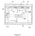
- the figures 5 and 5a illustrate another embodiment of the invention in which the box comprises two heating and recirculation devices, including two separate radial turbines 50A and 50B, the two turbines being arranged between them in a central symmetry on the central compartment of the box.
- the box thus comprises two hot gas circuits, the first circuit occupying a first half of the length of the main chamber while the second circuit occupies the second half.
- the first inlet orifice 47A, on which the first lateral discharge duct 52A opens for example has a length substantially equal to half that of the central compartment 40
- the second inlet orifice 47B, on which opens the second lateral blow duct 52B has a length substantially equal to half that of the central compartment 40.
- the two orifices together cover substantially the entire length of the central compartment 40.
- the two orifices 47A, 47B are in offset position on the opposite side walls 42, 44.
Landscapes
- Engineering & Computer Science (AREA)
- Mechanical Engineering (AREA)
- Chemical & Material Sciences (AREA)
- General Engineering & Computer Science (AREA)
- Life Sciences & Earth Sciences (AREA)
- Textile Engineering (AREA)
- General Chemical & Material Sciences (AREA)
- Chemical Kinetics & Catalysis (AREA)
- Physics & Mathematics (AREA)
- Health & Medical Sciences (AREA)
- Oral & Maxillofacial Surgery (AREA)
- Thermal Sciences (AREA)
- General Life Sciences & Earth Sciences (AREA)
- Geochemistry & Mineralogy (AREA)
- Materials Engineering (AREA)
- Organic Chemistry (AREA)
- Inorganic Chemistry (AREA)
- Combustion & Propulsion (AREA)
- Dispersion Chemistry (AREA)
- Environmental & Geological Engineering (AREA)
- Manufacturing & Machinery (AREA)
- Microbiology (AREA)
- Sustainable Development (AREA)
- Thermal Insulation (AREA)
- Drying Of Solid Materials (AREA)
- Tunnel Furnaces (AREA)
- Furnace Details (AREA)
Claims (15)
- Gehäuse (20) für einen Aushärtungsofen zur Vernetzung einer kontinuierlichen Matte (12) aus anorganischen oder pflanzlichen Fasern, umfassend eine zentrale Kammer (40), die durch seitliche (41-44), obere (45) und untere (46) Wände begrenzt wird, Ein- und Austrittsschleusen, die für den Durchgang einer Fasermatte bemessen sind, umfassend in der zentralen Kammer (40) Eintritts- (47) und Austrittsöffnungen (48) für einen heißen Gasstrom (30), die sich auf beiden Seiten der Fasermatte befinden, wobei das Gehäuse dadurch gekennzeichnet ist, dass es ferner eine integrierte Heiz- und Rückführvorrichtung für heißes Gas umfasst, die Folgendes umfasst:- mindestens eine radiale Turbine (50), die horizontal an der oberen Wand (45) oder der unteren Wand (46) der zentralen Kammer (40) montiert ist und deren Drehachse vertikal angeordnet ist, wobei die Turbine das heiße Gas entlang der Achse durch eine Austrittsöffnung (48) für Gas der zentralen Kammer (40) ansaugt und es radial zu Mitteln zum Rückführen (51, 52) abgibt,- Mittel zum Rückführen des Gases von der radialen Turbine (50) zur Gaseintrittsöffnung (47) in der Kammer(40), die mindestens teilweise auf mindestens einer Seitenwand (43, 44) der Kammer angeordnet sind,- mindestens eine Heizvorrichtung (53) für Luft, die in dem Gehäuse zirkuliert (20).
- Aushärtungsofen zur Vernetzung einer kontinuierlichen Matte (12) aus anorganischen oder pflanzlichen Fasern, umfassend:- eine Vielzahl von Heizgehäusen (20) nach Anspruch 1, die nacheinander von der Fasermatte (12) durchlaufen werden, wobei die Gehäuse jeweils eine zentralen Kammer (40) umfassen, die durch seitliche (41-44), obere (45) und untere (46) Wände begrenzt wird, wobei die Kammer Eintritts- (47) und Austrittsöffnungen (48) für einen heißen Gasstrom (30) umfasst, die sich auf beiden Seiten der Fasermatte befinden, sodass nachdem der heiße Gasstrom die Matte durchquert hat, das Bindemittel allmählich auf eine Temperatur gebracht wird, die über seiner Aushärtungstemperatur liegt,- mindestens eine Fördereinrichtung (18A, 18B) zum Transportieren der Matte durch die verschiedenen Gehäuse (20), wobei die Fördereinrichtung für den die Matte durchquerenden heißen Gasstrom durchlässig ist,- eine äußere Isolierhülle (49), die die Vielzahl von Gehäusen umgibt, wobei der Ofen dadurch gekennzeichnet ist, dass mindestens eines der Gehäuse ferner zwischen der äußeren Isolierhülle (49) und der zentralen Kammer (40) eine integrierte Heiz- und Rückführvorrichtung für heißes Gas umfasst, die Folgendes umfasst:- mindestens eine radiale Turbine (50), die horizontal an der oberen Wand (45) oder der unteren Wand (46) der zentralen Kammer (40) montiert ist, deren Drehachse vertikal angeordnet ist, wobei die Turbine das heiße Gas nach dem Durchqueren der Matte (12) entlang der Achse durch eine Gasaustrittsöffnung (48) der zentralen Kammer (40) ansaugt und es radial zu Mitteln zum Rückführen (51, 52) abgibt,- Mittel zum Rückführen (51, 52) des aus der radialen Turbine (50) austretenden heißen Gases bis zu einer Gaseintrittsöffnung (47) in der Kammer (40), wobei die Mittel zum Rückführen mindestens teilweise auf mindestens einer Seitenwand (43, 44) der Kammer angeordnet sind,- mindestens ein Mittel zum Heizen (53) des Gases, das in dem Gehäuse zirkuliert.
- Ofen nach Anspruch 2, wobei die Austrittsöffnung(en) (48) für den heißen Gasstrom (30) in der oberen Wand (45) der zentralen Kammer (40) ausgeführt ist/sind, und wobei die Turbine(n) (50) an der oberen Wand (45) der zentralen Kammer (40) montiert ist/sind, wobei der Eintritt einer Turbine gegenüber einer Austrittsöffnung (48) für heißes Gas angeordnet ist.
- Ofen nach Anspruch 2, wobei die Austrittsöffnung(en) (48) für den heißen Gasstrom (30) in der unteren Wand (46) der zentralen Kammer (40) ausgeführt ist/sind, und wobei die Turbine(n) (50) an der unteren Wand (46) der zentralen Kammer montiert ist/sind, wobei der Eintritt einer Turbine gegenüber einer Austrittsöffnung (48) für heißes Gas angeordnet ist.
- Ofen nach einem der Ansprüche 2 bis 4, wobei das Mittel zum Heizen (53) in das Gehäuse (20) eingebaut ist oder in dieses mündet.
- Ofen nach einem der Ansprüche 2 bis 5, wobei das Mittel zum Heizen (53) des Gases in der zentralen Kammer (40) zwischen der Fasermatte (12) und der Austrittsöffnung (48) für heißes Gas angeordnet ist und vorzugsweise in Form eines Strahlrohrs vorliegt.
- Ofen nach einem der Ansprüche 2 bis 6, wobei das Mittel zum Heizen (53) von Gas am Austritt der radialen Turbine (50) angeordnet ist, wobei das Mittel zum Heizen in die Mittel zum Rückführen (52) mündet oder darin vorgesehen ist.
- Ofen nach einem der Ansprüche 2 bis 7, wobei die Mittel zum Rückführen eine Expansionsdüse (51) in gasförmiger Verbindung mit dem Austritt der Turbine (50) umfassen, die hermetisch durch mindestens einen seitlichen Blaskanal (52) verlängert ist, der entlang einer Seitenwand (43) der zentralen Kammer (40) angeordnet ist, wobei der Blaskanal (52) an einer Eintrittsöffnung (47) der zentralen Kammer mündet.
- Ofen nach einem der Ansprüche 2 bis 8, wobei ein, vorzugsweise konvergenter, Ablasskanal eine Gasaustrittsöffnung (48) vertikal mit einem Eintritt der Turbine (50) verbindet.
- Ofen nach einem der Ansprüche 2 bis 9, wobei die Heiz- und Rückführvorrichtung eine einzige radiale Turbine (50) umfasst, die in der Mitte der oberen Wand (45) oder der unteren Wand (46) der zentralen Kammer (40) und gegenüber einer einzigen Austrittsöffnung (48) für heißes Gas angeordnet ist.
- Ofen nach einem der Ansprüche 2 bis 8, wobei die Heiz- und Rückführvorrichtung zwei radiale Turbinen (50A, 50B) umfasst, die vorzugsweise gemäß einer zentralen Symmetrie in Bezug auf die obere Wand (45) oder die untere Wand (46) der zentralen Kammer angeordnet sind.
- Ofen nach dem vorhergehenden Anspruch, wobei jede Turbine (50A, 50B) mit separaten Mitteln zum Rückführen verbunden ist, die Folgendes umfassen:- einen ersten Blaskanal (51A) in fluider Verbindung mit einer ersten radialen Turbine (50A), wobei der Blaskanal (51A) an einer ersten Seitenwand (43) der Kammer vorgesehen ist und an einer ersten Eintrittsöffnung (47A) mündet, die auf der ersten Seitenwand (43) ausgeführt ist,- einen zweiten Blaskanal (51B) in fluider Verbindung mit der zweiten radialen Turbine (50B), wobei der Blaskanal (51B) an der gegenüberliegenden Seitenwand (44) der Kammer (40) vorgesehen ist und an einer ersten Eintrittsöffnung (47B) mündet, die auf einer gegenüberliegenden Seitenwand (44) ausgeführt ist.
- Ofen nach dem vorhergehenden Anspruch, wobei:- die erste Eintrittsöffnung (47A), an der der erste Blaskanal (52A) mündet, eine Länge zwischen dem 0,4- und 0,6-Fachen der Länge der zentralen Kammer (40) aufweist,- die zweite Eintrittsöffnung (47B), an der der zweite Blaskanal (52B) mündet, eine Länge zwischen dem 0,4- und 0,6-Fachen der Länge der zentralen Kammer (40) aufweist,- die beiden Öffnungen zusammen mindestens das 0,8-Fache der Länge der zentralen Kammer (40) abdecken,- die beiden Öffnungen (47A, 47B) sich in einer versetzten Position auf den gegenüberliegenden Seitenwänden (43, 44) befinden.
- Ofen nach einem der Ansprüche 2 bis 13, wobei zwischen der zentralen Kammer und mindestens einem Blaskanal eine Umgehungsöffnung (Bypass) für heißes Gas vorgesehen ist.
- Produktionslinie für eine kontinuierliche Matte aus anorganischen und/oder pflanzlichen Fasern, umfassend mindestens eine Einheit zum Ziehen von Fasern einer kontinuierlichen Matte aus anorganischen und/oder pflanzlichen Fasern, eine Fördereinrichtung zum Transportieren der Matte und einen Ofen nach einem der Ansprüche 2 bis 14.
Applications Claiming Priority (2)
| Application Number | Priority Date | Filing Date | Title |
|---|---|---|---|
| FR1555612A FR3037640B1 (fr) | 2015-06-19 | 2015-06-19 | Etuve de reticulation d'un matelas continu de fibres minerales ou vegetales |
| PCT/FR2016/051477 WO2016203170A1 (fr) | 2015-06-19 | 2016-06-17 | Etuve de reticulation d'un matelas continu de fibres minerales ou vegetales |
Publications (2)
| Publication Number | Publication Date |
|---|---|
| EP3311088A1 EP3311088A1 (de) | 2018-04-25 |
| EP3311088B1 true EP3311088B1 (de) | 2019-08-21 |
Family
ID=55072752
Family Applications (1)
| Application Number | Title | Priority Date | Filing Date |
|---|---|---|---|
| EP16736532.9A Active EP3311088B1 (de) | 2015-06-19 | 2016-06-17 | Gehäuse für aushärtungsofen und aushärtungsofen zur vernetzung einer kontinuierlichen matte aus anorganischen oder pflanzlichen fasern |
Country Status (7)
| Country | Link |
|---|---|
| US (1) | US20180156539A1 (de) |
| EP (1) | EP3311088B1 (de) |
| JP (1) | JP2018524541A (de) |
| CN (1) | CN107709913A (de) |
| CA (1) | CA2987089A1 (de) |
| FR (1) | FR3037640B1 (de) |
| WO (1) | WO2016203170A1 (de) |
Families Citing this family (11)
| Publication number | Priority date | Publication date | Assignee | Title |
|---|---|---|---|---|
| MX380274B (es) | 2011-06-30 | 2025-03-12 | Gallo Winery E & J | Colorante cristalino natural y proceso para producción. |
| AU2014232364B2 (en) | 2013-03-15 | 2018-07-12 | E & J Gallo Winery | Dryer using adjustable conditioned air flow |
| TWI585345B (zh) * | 2016-08-15 | 2017-06-01 | 台技工業設備股份有限公司 | 廢氣排出系統及廢氣排出方法 |
| US11221179B2 (en) | 2018-10-26 | 2022-01-11 | E. & J. Gallo Winery | Low profile design air tunnel system and method for providing uniform air flow in a refractance window dryer |
| CN111189320A (zh) * | 2019-12-28 | 2020-05-22 | 苏州椰为媒纤维制品科技有限公司 | 一种棕垫用连续烘烤定型设备 |
| FR3106655B1 (fr) * | 2020-01-24 | 2021-12-24 | Alfi Technonogies | Etuve de polymérisation pour matelas en fibres minérales |
| FR3118485B1 (fr) * | 2020-12-30 | 2023-04-21 | Alfi Tech | Etuve de séchage et/ou polymérisation avec système d’extraction amélioré |
| FR3136785B1 (fr) | 2022-06-20 | 2024-10-25 | Saint Gobain Isover | Système et procédé pour la fabrication d’un matelas continu de fibres minérales et/ou végétales |
| FR3136784B1 (fr) | 2022-06-20 | 2024-10-25 | Saint Gobain Isover | Système et procédé de réticulation d’un matelas continu de fibres minérales et/ou végétales |
| FR3153882A1 (fr) * | 2023-10-06 | 2025-04-11 | Saint-Gobain Isover | Etuve de réticulation comprenant un moyen de chauffage électrique disposé dans la chambre de combustion |
| KR102830126B1 (ko) * | 2024-08-30 | 2025-07-08 | 주식회사 에코넥스트 | 슬러지 연속 처리 설비 및 처리 공정 |
Citations (8)
| Publication number | Priority date | Publication date | Assignee | Title |
|---|---|---|---|---|
| US2674811A (en) | 1950-11-17 | 1954-04-13 | Us Rubber Co | Drier for porous materials |
| US2997096A (en) | 1957-05-16 | 1961-08-22 | Owens Corning Fiberglass Corp | Multiple stage methods and apparatus for curing the binder of fibrous glass masses |
| US4263007A (en) | 1978-06-05 | 1981-04-21 | Saint-Gobain Industries | Apparatus for heat treatment of fibrous mats |
| US5639418A (en) | 1996-03-25 | 1997-06-17 | Surface Combustion, Inc. | Strip floater furnace with closed loop recirculation |
| WO2003083394A1 (de) | 2002-04-02 | 2003-10-09 | Solipat Ag | Vorrichtung und verfahren zum verfestigen eines faserverbundes |
| EP0958117B1 (de) | 1996-03-19 | 2004-01-02 | Herbert G. Nopper | Verfahren und heizvorrichtung zum vorerwärmen von vliesen aus spänen oder fasern |
| US20060103059A1 (en) | 2004-10-29 | 2006-05-18 | Crafton Scott P | High pressure heat treatment system |
| FR2984371A1 (fr) | 2011-12-20 | 2013-06-21 | Saint Gobain Isover | Etuve pour la fabrication d'un produit en laine minerale |
Family Cites Families (7)
| Publication number | Priority date | Publication date | Assignee | Title |
|---|---|---|---|---|
| US2338839A (en) * | 1941-11-25 | 1944-01-11 | Johns Manville | Method of manufacturing mineral wool products |
| US4065251A (en) * | 1976-08-03 | 1977-12-27 | Associated Electrical Industries Limited | Furnaces |
| FI811410L (fi) * | 1981-05-07 | 1982-11-08 | Asko Upo Oy | Foerfarande foer uppvaermning av aendan i ett plastroer och cirkulationsluftugn foer utfoerande av foerfarandet. ec;g;820614:17;l |
| DE3909175C3 (de) * | 1989-03-21 | 1995-08-31 | Heinz Dipl Ing Reinbold | Vorrichtung zur Behandlung von Monofilen |
| EP0770842B1 (de) * | 1995-09-26 | 1999-04-14 | DEA TECH MACHINERY S.p.A. | Emallierofen für fadenförmige Materialen |
| DE202004014949U1 (de) * | 2004-09-25 | 2004-11-18 | Techno-Grafica Gmbh | Vorrichtung zum Wärmebehandeln einer Beschichtung von Flachoffset-Druckplatten |
| CN202653140U (zh) * | 2012-04-17 | 2013-01-09 | 杜晋太 | 烘烤房 |
-
2015
- 2015-06-19 FR FR1555612A patent/FR3037640B1/fr not_active Expired - Fee Related
-
2016
- 2016-06-17 WO PCT/FR2016/051477 patent/WO2016203170A1/fr not_active Ceased
- 2016-06-17 CN CN201680036019.9A patent/CN107709913A/zh active Pending
- 2016-06-17 US US15/736,870 patent/US20180156539A1/en not_active Abandoned
- 2016-06-17 JP JP2017565787A patent/JP2018524541A/ja not_active Withdrawn
- 2016-06-17 EP EP16736532.9A patent/EP3311088B1/de active Active
- 2016-06-17 CA CA2987089A patent/CA2987089A1/fr not_active Abandoned
Patent Citations (8)
| Publication number | Priority date | Publication date | Assignee | Title |
|---|---|---|---|---|
| US2674811A (en) | 1950-11-17 | 1954-04-13 | Us Rubber Co | Drier for porous materials |
| US2997096A (en) | 1957-05-16 | 1961-08-22 | Owens Corning Fiberglass Corp | Multiple stage methods and apparatus for curing the binder of fibrous glass masses |
| US4263007A (en) | 1978-06-05 | 1981-04-21 | Saint-Gobain Industries | Apparatus for heat treatment of fibrous mats |
| EP0958117B1 (de) | 1996-03-19 | 2004-01-02 | Herbert G. Nopper | Verfahren und heizvorrichtung zum vorerwärmen von vliesen aus spänen oder fasern |
| US5639418A (en) | 1996-03-25 | 1997-06-17 | Surface Combustion, Inc. | Strip floater furnace with closed loop recirculation |
| WO2003083394A1 (de) | 2002-04-02 | 2003-10-09 | Solipat Ag | Vorrichtung und verfahren zum verfestigen eines faserverbundes |
| US20060103059A1 (en) | 2004-10-29 | 2006-05-18 | Crafton Scott P | High pressure heat treatment system |
| FR2984371A1 (fr) | 2011-12-20 | 2013-06-21 | Saint Gobain Isover | Etuve pour la fabrication d'un produit en laine minerale |
Also Published As
| Publication number | Publication date |
|---|---|
| EP3311088A1 (de) | 2018-04-25 |
| CN107709913A (zh) | 2018-02-16 |
| US20180156539A1 (en) | 2018-06-07 |
| JP2018524541A (ja) | 2018-08-30 |
| WO2016203170A1 (fr) | 2016-12-22 |
| CA2987089A1 (fr) | 2016-12-22 |
| FR3037640A1 (fr) | 2016-12-23 |
| FR3037640B1 (fr) | 2017-06-16 |
Similar Documents
| Publication | Publication Date | Title |
|---|---|---|
| WO2016203170A1 (fr) | Etuve de reticulation d'un matelas continu de fibres minerales ou vegetales | |
| EP2627960B1 (de) | Ofen zur herstellung eines mineralwollerzeugnisses | |
| CA1214331A (fr) | Dispositif pour l'aide au soutien d'une plaque de verre portee a sa temperature de deformation et reposant simultanement sur des appuis mecaniques | |
| EP2880210B1 (de) | Verfahren zur härtung einer kontinuierlichen matte aus anorganischen oder pflanzenfasern | |
| EP0410889B1 (de) | Verfahren und Vorrichtung zur Behandlung von Abfallglas oder Mineralfasern für ihre Rückgewinnung | |
| EP3240922B1 (de) | Verfahren zur messung innerhalb einer matte aus mineral- oder pflanzenfasern | |
| EP0020260A1 (de) | Verfahren und Vorrichtung zum Trocknen verglasbarer verdichteter Mischungen | |
| EP0000111B1 (de) | Vorrichtung zur Warmbehandlung einer Fasermatte mit Wärmehärtbarem Bindemittel | |
| EP0208620B1 (de) | Trocken- und Brenneinrichtungen für keramische Erzeugnisse | |
| EP0137881A1 (de) | Verfahren und Vorrichtung zum Schmelzen von glasartigen mineralischen Materialien | |
| EP1794383B1 (de) | Verfahren zur härtung eines bindemittels auf isolierfasern | |
| EP4540447B1 (de) | System und verfahren zur vernetzung einer kontinuierlichen matte aus mineral- und/oder pflanzenfasern | |
| WO2023247499A1 (fr) | Système et procédé pour la fabrication d'un matelas continu de fibres minérales et/ou végétales | |
| EP1230508B1 (de) | Verfahren zur aufbringung einer isolationsschicht auf die oberfläche des zu isolierenden objekts | |
| EP1644680A2 (de) | Verfahren und vorrichtung zum trocknen eines nichtmetallischen überzugs auf einem stahlband | |
| EP0462678A1 (de) | Vorrichtung zur Behandlung von feinkörnigem Rohstoff wie Kalziumsulfat zum Herstellen eines hydraulischen Bindemittels |
Legal Events
| Date | Code | Title | Description |
|---|---|---|---|
| STAA | Information on the status of an ep patent application or granted ep patent |
Free format text: STATUS: THE INTERNATIONAL PUBLICATION HAS BEEN MADE |
|
| PUAI | Public reference made under article 153(3) epc to a published international application that has entered the european phase |
Free format text: ORIGINAL CODE: 0009012 |
|
| STAA | Information on the status of an ep patent application or granted ep patent |
Free format text: STATUS: REQUEST FOR EXAMINATION WAS MADE |
|
| 17P | Request for examination filed |
Effective date: 20180119 |
|
| AK | Designated contracting states |
Kind code of ref document: A1 Designated state(s): AL AT BE BG CH CY CZ DE DK EE ES FI FR GB GR HR HU IE IS IT LI LT LU LV MC MK MT NL NO PL PT RO RS SE SI SK SM TR |
|
| AX | Request for extension of the european patent |
Extension state: BA ME |
|
| DAV | Request for validation of the european patent (deleted) | ||
| DAX | Request for extension of the european patent (deleted) | ||
| GRAP | Despatch of communication of intention to grant a patent |
Free format text: ORIGINAL CODE: EPIDOSNIGR1 |
|
| STAA | Information on the status of an ep patent application or granted ep patent |
Free format text: STATUS: GRANT OF PATENT IS INTENDED |
|
| RIC1 | Information provided on ipc code assigned before grant |
Ipc: F27B 9/10 20060101ALI20181211BHEP Ipc: F27D 17/00 20060101ALI20181211BHEP Ipc: C03B 37/04 20060101ALI20181211BHEP Ipc: C03C 25/64 20060101ALI20181211BHEP Ipc: F27B 9/30 20060101ALI20181211BHEP Ipc: C03C 25/26 20180101AFI20181211BHEP |
|
| INTG | Intention to grant announced |
Effective date: 20190107 |
|
| GRAJ | Information related to disapproval of communication of intention to grant by the applicant or resumption of examination proceedings by the epo deleted |
Free format text: ORIGINAL CODE: EPIDOSDIGR1 |
|
| REG | Reference to a national code |
Ref country code: DE Ref legal event code: R079 Ref document number: 602016019037 Country of ref document: DE Free format text: PREVIOUS MAIN CLASS: F27B0009100000 Ipc: C03C0025260000 |
|
| STAA | Information on the status of an ep patent application or granted ep patent |
Free format text: STATUS: REQUEST FOR EXAMINATION WAS MADE |
|
| GRAJ | Information related to disapproval of communication of intention to grant by the applicant or resumption of examination proceedings by the epo deleted |
Free format text: ORIGINAL CODE: EPIDOSDIGR1 |
|
| GRAP | Despatch of communication of intention to grant a patent |
Free format text: ORIGINAL CODE: EPIDOSNIGR1 |
|
| GRAJ | Information related to disapproval of communication of intention to grant by the applicant or resumption of examination proceedings by the epo deleted |
Free format text: ORIGINAL CODE: EPIDOSDIGR1 |
|
| GRAP | Despatch of communication of intention to grant a patent |
Free format text: ORIGINAL CODE: EPIDOSNIGR1 |
|
| GRAR | Information related to intention to grant a patent recorded |
Free format text: ORIGINAL CODE: EPIDOSNIGR71 |
|
| GRAS | Grant fee paid |
Free format text: ORIGINAL CODE: EPIDOSNIGR3 |
|
| STAA | Information on the status of an ep patent application or granted ep patent |
Free format text: STATUS: GRANT OF PATENT IS INTENDED |
|
| INTC | Intention to grant announced (deleted) | ||
| RIC1 | Information provided on ipc code assigned before grant |
Ipc: D04H 1/645 20120101ALI20190513BHEP Ipc: B29C 35/06 20060101ALI20190513BHEP Ipc: F26B 3/06 20060101ALI20190513BHEP Ipc: C03C 25/64 20060101ALI20190513BHEP Ipc: F27B 9/30 20060101ALI20190513BHEP Ipc: C03C 25/26 20180101AFI20190513BHEP Ipc: F26B 23/00 20060101ALI20190513BHEP Ipc: B29C 67/24 20060101ALI20190513BHEP Ipc: C03B 37/04 20060101ALI20190513BHEP Ipc: F26B 13/10 20060101ALI20190513BHEP Ipc: D04H 1/4218 20120101ALI20190513BHEP Ipc: F27D 17/00 20060101ALI20190513BHEP Ipc: F27B 9/10 20060101ALI20190513BHEP Ipc: D04H 1/4209 20120101ALI20190513BHEP Ipc: F26B 25/00 20060101ALI20190513BHEP Ipc: B29C 35/04 20060101ALI20190513BHEP |
|
| INTG | Intention to grant announced |
Effective date: 20190528 |
|
| GRAA | (expected) grant |
Free format text: ORIGINAL CODE: 0009210 |
|
| STAA | Information on the status of an ep patent application or granted ep patent |
Free format text: STATUS: THE PATENT HAS BEEN GRANTED |
|
| AK | Designated contracting states |
Kind code of ref document: B1 Designated state(s): AL AT BE BG CH CY CZ DE DK EE ES FI FR GB GR HR HU IE IS IT LI LT LU LV MC MK MT NL NO PL PT RO RS SE SI SK SM TR |
|
| REG | Reference to a national code |
Ref country code: GB Ref legal event code: FG4D Free format text: NOT ENGLISH |
|
| REG | Reference to a national code |
Ref country code: CH Ref legal event code: EP |
|
| REG | Reference to a national code |
Ref country code: DE Ref legal event code: R096 Ref document number: 602016019037 Country of ref document: DE |
|
| REG | Reference to a national code |
Ref country code: AT Ref legal event code: REF Ref document number: 1169560 Country of ref document: AT Kind code of ref document: T Effective date: 20190915 |
|
| REG | Reference to a national code |
Ref country code: IE Ref legal event code: FG4D Free format text: LANGUAGE OF EP DOCUMENT: FRENCH |
|
| REG | Reference to a national code |
Ref country code: LT Ref legal event code: MG4D |
|
| REG | Reference to a national code |
Ref country code: NL Ref legal event code: MP Effective date: 20190821 |
|
| PG25 | Lapsed in a contracting state [announced via postgrant information from national office to epo] |
Ref country code: PT Free format text: LAPSE BECAUSE OF FAILURE TO SUBMIT A TRANSLATION OF THE DESCRIPTION OR TO PAY THE FEE WITHIN THE PRESCRIBED TIME-LIMIT Effective date: 20191223 Ref country code: NO Free format text: LAPSE BECAUSE OF FAILURE TO SUBMIT A TRANSLATION OF THE DESCRIPTION OR TO PAY THE FEE WITHIN THE PRESCRIBED TIME-LIMIT Effective date: 20191121 Ref country code: NL Free format text: LAPSE BECAUSE OF FAILURE TO SUBMIT A TRANSLATION OF THE DESCRIPTION OR TO PAY THE FEE WITHIN THE PRESCRIBED TIME-LIMIT Effective date: 20190821 Ref country code: BG Free format text: LAPSE BECAUSE OF FAILURE TO SUBMIT A TRANSLATION OF THE DESCRIPTION OR TO PAY THE FEE WITHIN THE PRESCRIBED TIME-LIMIT Effective date: 20191121 Ref country code: FI Free format text: LAPSE BECAUSE OF FAILURE TO SUBMIT A TRANSLATION OF THE DESCRIPTION OR TO PAY THE FEE WITHIN THE PRESCRIBED TIME-LIMIT Effective date: 20190821 Ref country code: LT Free format text: LAPSE BECAUSE OF FAILURE TO SUBMIT A TRANSLATION OF THE DESCRIPTION OR TO PAY THE FEE WITHIN THE PRESCRIBED TIME-LIMIT Effective date: 20190821 Ref country code: HR Free format text: LAPSE BECAUSE OF FAILURE TO SUBMIT A TRANSLATION OF THE DESCRIPTION OR TO PAY THE FEE WITHIN THE PRESCRIBED TIME-LIMIT Effective date: 20190821 Ref country code: SE Free format text: LAPSE BECAUSE OF FAILURE TO SUBMIT A TRANSLATION OF THE DESCRIPTION OR TO PAY THE FEE WITHIN THE PRESCRIBED TIME-LIMIT Effective date: 20190821 |
|
| PG25 | Lapsed in a contracting state [announced via postgrant information from national office to epo] |
Ref country code: AL Free format text: LAPSE BECAUSE OF FAILURE TO SUBMIT A TRANSLATION OF THE DESCRIPTION OR TO PAY THE FEE WITHIN THE PRESCRIBED TIME-LIMIT Effective date: 20190821 Ref country code: ES Free format text: LAPSE BECAUSE OF FAILURE TO SUBMIT A TRANSLATION OF THE DESCRIPTION OR TO PAY THE FEE WITHIN THE PRESCRIBED TIME-LIMIT Effective date: 20190821 Ref country code: GR Free format text: LAPSE BECAUSE OF FAILURE TO SUBMIT A TRANSLATION OF THE DESCRIPTION OR TO PAY THE FEE WITHIN THE PRESCRIBED TIME-LIMIT Effective date: 20191122 Ref country code: IS Free format text: LAPSE BECAUSE OF FAILURE TO SUBMIT A TRANSLATION OF THE DESCRIPTION OR TO PAY THE FEE WITHIN THE PRESCRIBED TIME-LIMIT Effective date: 20191221 Ref country code: RS Free format text: LAPSE BECAUSE OF FAILURE TO SUBMIT A TRANSLATION OF THE DESCRIPTION OR TO PAY THE FEE WITHIN THE PRESCRIBED TIME-LIMIT Effective date: 20190821 Ref country code: LV Free format text: LAPSE BECAUSE OF FAILURE TO SUBMIT A TRANSLATION OF THE DESCRIPTION OR TO PAY THE FEE WITHIN THE PRESCRIBED TIME-LIMIT Effective date: 20190821 |
|
| REG | Reference to a national code |
Ref country code: AT Ref legal event code: MK05 Ref document number: 1169560 Country of ref document: AT Kind code of ref document: T Effective date: 20190821 |
|
| PG25 | Lapsed in a contracting state [announced via postgrant information from national office to epo] |
Ref country code: TR Free format text: LAPSE BECAUSE OF FAILURE TO SUBMIT A TRANSLATION OF THE DESCRIPTION OR TO PAY THE FEE WITHIN THE PRESCRIBED TIME-LIMIT Effective date: 20190821 |
|
| PG25 | Lapsed in a contracting state [announced via postgrant information from national office to epo] |
Ref country code: RO Free format text: LAPSE BECAUSE OF FAILURE TO SUBMIT A TRANSLATION OF THE DESCRIPTION OR TO PAY THE FEE WITHIN THE PRESCRIBED TIME-LIMIT Effective date: 20190821 Ref country code: IT Free format text: LAPSE BECAUSE OF FAILURE TO SUBMIT A TRANSLATION OF THE DESCRIPTION OR TO PAY THE FEE WITHIN THE PRESCRIBED TIME-LIMIT Effective date: 20190821 Ref country code: DK Free format text: LAPSE BECAUSE OF FAILURE TO SUBMIT A TRANSLATION OF THE DESCRIPTION OR TO PAY THE FEE WITHIN THE PRESCRIBED TIME-LIMIT Effective date: 20190821 Ref country code: EE Free format text: LAPSE BECAUSE OF FAILURE TO SUBMIT A TRANSLATION OF THE DESCRIPTION OR TO PAY THE FEE WITHIN THE PRESCRIBED TIME-LIMIT Effective date: 20190821 Ref country code: PL Free format text: LAPSE BECAUSE OF FAILURE TO SUBMIT A TRANSLATION OF THE DESCRIPTION OR TO PAY THE FEE WITHIN THE PRESCRIBED TIME-LIMIT Effective date: 20190821 Ref country code: AT Free format text: LAPSE BECAUSE OF FAILURE TO SUBMIT A TRANSLATION OF THE DESCRIPTION OR TO PAY THE FEE WITHIN THE PRESCRIBED TIME-LIMIT Effective date: 20190821 |
|
| REG | Reference to a national code |
Ref country code: DE Ref legal event code: R026 Ref document number: 602016019037 Country of ref document: DE |
|
| PG25 | Lapsed in a contracting state [announced via postgrant information from national office to epo] |
Ref country code: IS Free format text: LAPSE BECAUSE OF FAILURE TO SUBMIT A TRANSLATION OF THE DESCRIPTION OR TO PAY THE FEE WITHIN THE PRESCRIBED TIME-LIMIT Effective date: 20200224 Ref country code: CZ Free format text: LAPSE BECAUSE OF FAILURE TO SUBMIT A TRANSLATION OF THE DESCRIPTION OR TO PAY THE FEE WITHIN THE PRESCRIBED TIME-LIMIT Effective date: 20190821 Ref country code: SK Free format text: LAPSE BECAUSE OF FAILURE TO SUBMIT A TRANSLATION OF THE DESCRIPTION OR TO PAY THE FEE WITHIN THE PRESCRIBED TIME-LIMIT Effective date: 20190821 Ref country code: SM Free format text: LAPSE BECAUSE OF FAILURE TO SUBMIT A TRANSLATION OF THE DESCRIPTION OR TO PAY THE FEE WITHIN THE PRESCRIBED TIME-LIMIT Effective date: 20190821 |
|
| PLBI | Opposition filed |
Free format text: ORIGINAL CODE: 0009260 |
|
| RAP2 | Party data changed (patent owner data changed or rights of a patent transferred) |
Owner name: SAINT-GOBAIN ISOVER |
|
| PLAX | Notice of opposition and request to file observation + time limit sent |
Free format text: ORIGINAL CODE: EPIDOSNOBS2 |
|
| 26 | Opposition filed |
Opponent name: URSA INSULATION S.A. Effective date: 20200522 |
|
| PG2D | Information on lapse in contracting state deleted |
Ref country code: IS |
|
| PG25 | Lapsed in a contracting state [announced via postgrant information from national office to epo] |
Ref country code: SI Free format text: LAPSE BECAUSE OF FAILURE TO SUBMIT A TRANSLATION OF THE DESCRIPTION OR TO PAY THE FEE WITHIN THE PRESCRIBED TIME-LIMIT Effective date: 20190821 |
|
| PLBB | Reply of patent proprietor to notice(s) of opposition received |
Free format text: ORIGINAL CODE: EPIDOSNOBS3 |
|
| PG25 | Lapsed in a contracting state [announced via postgrant information from national office to epo] |
Ref country code: MC Free format text: LAPSE BECAUSE OF FAILURE TO SUBMIT A TRANSLATION OF THE DESCRIPTION OR TO PAY THE FEE WITHIN THE PRESCRIBED TIME-LIMIT Effective date: 20190821 |
|
| REG | Reference to a national code |
Ref country code: CH Ref legal event code: PL |
|
| PG25 | Lapsed in a contracting state [announced via postgrant information from national office to epo] |
Ref country code: LU Free format text: LAPSE BECAUSE OF NON-PAYMENT OF DUE FEES Effective date: 20200617 |
|
| PG25 | Lapsed in a contracting state [announced via postgrant information from national office to epo] |
Ref country code: IE Free format text: LAPSE BECAUSE OF NON-PAYMENT OF DUE FEES Effective date: 20200617 Ref country code: CH Free format text: LAPSE BECAUSE OF NON-PAYMENT OF DUE FEES Effective date: 20200630 Ref country code: LI Free format text: LAPSE BECAUSE OF NON-PAYMENT OF DUE FEES Effective date: 20200630 |
|
| PLBP | Opposition withdrawn |
Free format text: ORIGINAL CODE: 0009264 |
|
| PLBD | Termination of opposition procedure: decision despatched |
Free format text: ORIGINAL CODE: EPIDOSNOPC1 |
|
| REG | Reference to a national code |
Ref country code: DE Ref legal event code: R100 Ref document number: 602016019037 Country of ref document: DE |
|
| PLBM | Termination of opposition procedure: date of legal effect published |
Free format text: ORIGINAL CODE: 0009276 |
|
| PG25 | Lapsed in a contracting state [announced via postgrant information from national office to epo] |
Ref country code: MT Free format text: LAPSE BECAUSE OF FAILURE TO SUBMIT A TRANSLATION OF THE DESCRIPTION OR TO PAY THE FEE WITHIN THE PRESCRIBED TIME-LIMIT Effective date: 20190821 Ref country code: CY Free format text: LAPSE BECAUSE OF FAILURE TO SUBMIT A TRANSLATION OF THE DESCRIPTION OR TO PAY THE FEE WITHIN THE PRESCRIBED TIME-LIMIT Effective date: 20190821 |
|
| 27C | Opposition proceedings terminated |
Effective date: 20220204 |
|
| PG25 | Lapsed in a contracting state [announced via postgrant information from national office to epo] |
Ref country code: MK Free format text: LAPSE BECAUSE OF FAILURE TO SUBMIT A TRANSLATION OF THE DESCRIPTION OR TO PAY THE FEE WITHIN THE PRESCRIBED TIME-LIMIT Effective date: 20190821 |
|
| P01 | Opt-out of the competence of the unified patent court (upc) registered |
Effective date: 20230421 |
|
| PGFP | Annual fee paid to national office [announced via postgrant information from national office to epo] |
Ref country code: DE Payment date: 20250429 Year of fee payment: 10 |
|
| PGFP | Annual fee paid to national office [announced via postgrant information from national office to epo] |
Ref country code: GB Payment date: 20250501 Year of fee payment: 10 |
|
| PGFP | Annual fee paid to national office [announced via postgrant information from national office to epo] |
Ref country code: BE Payment date: 20250516 Year of fee payment: 10 |
|
| PGFP | Annual fee paid to national office [announced via postgrant information from national office to epo] |
Ref country code: FR Payment date: 20250508 Year of fee payment: 10 |