EP3311107B1 - Procédé et circuit pour détecter une ligne d'excitation ouverte d'un résolveur - Google Patents
Procédé et circuit pour détecter une ligne d'excitation ouverte d'un résolveur Download PDFInfo
- Publication number
- EP3311107B1 EP3311107B1 EP16729519.5A EP16729519A EP3311107B1 EP 3311107 B1 EP3311107 B1 EP 3311107B1 EP 16729519 A EP16729519 A EP 16729519A EP 3311107 B1 EP3311107 B1 EP 3311107B1
- Authority
- EP
- European Patent Office
- Prior art keywords
- exciter
- voltage
- resolver
- coil
- connections
- Prior art date
- Legal status (The legal status is an assumption and is not a legal conclusion. Google has not performed a legal analysis and makes no representation as to the accuracy of the status listed.)
- Active
Links
Images
Classifications
-
- G—PHYSICS
- G01—MEASURING; TESTING
- G01R—MEASURING ELECTRIC VARIABLES; MEASURING MAGNETIC VARIABLES
- G01R31/00—Arrangements for testing electric properties; Arrangements for locating electric faults; Arrangements for electrical testing characterised by what is being tested not provided for elsewhere
- G01R31/50—Testing of electric apparatus, lines, cables or components for short-circuits, continuity, leakage current or incorrect line connections
- G01R31/55—Testing for incorrect line connections
-
- G—PHYSICS
- G01—MEASURING; TESTING
- G01D—MEASURING NOT SPECIALLY ADAPTED FOR A SPECIFIC VARIABLE; ARRANGEMENTS FOR MEASURING TWO OR MORE VARIABLES NOT COVERED IN A SINGLE OTHER SUBCLASS; TARIFF METERING APPARATUS; MEASURING OR TESTING NOT OTHERWISE PROVIDED FOR
- G01D18/00—Testing or calibrating apparatus or arrangements provided for in groups G01D1/00 - G01D15/00
-
- G—PHYSICS
- G01—MEASURING; TESTING
- G01D—MEASURING NOT SPECIALLY ADAPTED FOR A SPECIFIC VARIABLE; ARRANGEMENTS FOR MEASURING TWO OR MORE VARIABLES NOT COVERED IN A SINGLE OTHER SUBCLASS; TARIFF METERING APPARATUS; MEASURING OR TESTING NOT OTHERWISE PROVIDED FOR
- G01D5/00—Mechanical means for transferring the output of a sensing member; Means for converting the output of a sensing member to another variable where the form or nature of the sensing member does not constrain the means for converting; Transducers not specially adapted for a specific variable
- G01D5/12—Mechanical means for transferring the output of a sensing member; Means for converting the output of a sensing member to another variable where the form or nature of the sensing member does not constrain the means for converting; Transducers not specially adapted for a specific variable using electric or magnetic means
- G01D5/14—Mechanical means for transferring the output of a sensing member; Means for converting the output of a sensing member to another variable where the form or nature of the sensing member does not constrain the means for converting; Transducers not specially adapted for a specific variable using electric or magnetic means influencing the magnitude of a current or voltage
- G01D5/20—Mechanical means for transferring the output of a sensing member; Means for converting the output of a sensing member to another variable where the form or nature of the sensing member does not constrain the means for converting; Transducers not specially adapted for a specific variable using electric or magnetic means influencing the magnitude of a current or voltage by varying inductance, e.g. by a movable armature
-
- G—PHYSICS
- G01—MEASURING; TESTING
- G01R—MEASURING ELECTRIC VARIABLES; MEASURING MAGNETIC VARIABLES
- G01R31/00—Arrangements for testing electric properties; Arrangements for locating electric faults; Arrangements for electrical testing characterised by what is being tested not provided for elsewhere
- G01R31/28—Testing of electronic circuits, e.g. by signal tracer
- G01R31/282—Testing of electronic circuits specially adapted for particular applications not provided for elsewhere
- G01R31/2829—Testing of circuits in sensor or actuator systems
-
- G—PHYSICS
- G01—MEASURING; TESTING
- G01B—MEASURING LENGTH, THICKNESS OR SIMILAR LINEAR DIMENSIONS; MEASURING ANGLES; MEASURING AREAS; MEASURING IRREGULARITIES OF SURFACES OR CONTOURS
- G01B7/00—Measuring arrangements characterised by the use of electric or magnetic techniques
- G01B7/30—Measuring arrangements characterised by the use of electric or magnetic techniques for measuring angles or tapers; for testing the alignment of axes
Definitions
- the invention relates to a method for detecting an open resolver excitation line and a circuit for implementing this method.
- Resolvers are used to determine the angular position of a rotating object, such as the drive shaft of an engine.
- resolver types There are different resolver types in the prior art. Basically, by means of at least one coil, a changing magnetic field is generated, and by means of at least one other coil, this field is detected, wherein the strength of the coupling between the coils varies depending on the position to be measured or angular position.
- the Variable Reluctance Resolver uses only one exciter coil, and there are two coils that generate position-dependent signals.
- the German patent application DE 10 2011 078 583 A1 discloses, for example, an evaluation of resolver sensor signals in a vehicle.
- a resolver receives a rotational movement of a rotor for this purpose, and a processor element processes the sinusoidal or cosinusoidal output signals of the resolver.
- JP2012098188 discloses an apparatus for detecting an open exciter line of a resolver.
- the invention is based on such a resolver, wherein the excitation signal is sinusoidal and typically has a frequency of 10 kHz.
- the two measuring coils are usually positioned orthogonal to each other and are referred to as sine and cosine coil. With the two measurement signals, the angle of the DUT can be determined unambiguously.
- the excitation signal for the excitation coil can be provided for example by two push-pull output stages, one for each of the two terminals of the exciter coil.
- the output signals of the two output stages are then phase-shifted by 180 ° to each other and the effective for the exciter coil excitation signal is the difference voltage between the outputs of the two output stages.
- the excitation coil through only one power amplifier.
- the second terminal of the excitation coil is then either directly or via a capacitor to a fixed potential, e.g. Ground potential laid.
- the receiver coils produces an AC signal with the same frequency as the excitation signal, the amplitude of which is modulated according to the rotor position, wherein the signal on the cosine coil is phase-shifted by 90 ° relative to the signal on the sinusoidal coil.
- Resolvers are often used to control permanent magnet synchronous machines (PSM) and electrically excited synchronous machines (ESM), which are used e.g. used as drive for hybrid and electric vehicles. For such a regulation, the knowledge of the current rotor angle position is necessary. In the control of asynchronous machines (ASM) knowledge of the current frequency of the drive is required.
- PSM permanent magnet synchronous machines
- ESM electrically excited synchronous machines
- resolvers are preferably used in motor vehicles for these purposes, although there are alternative sensors, e.g. digital angle sensors or sensors based on the eddy current effect.
- Resolvers as the subject of the present application, is a possible fault to be diagnosed an open line in the excitation path of the resolver, ie at least one terminal of the excitation coil has no electrical connection to the drive more, or there is a cable break within the exciter coil ,
- the method for detecting an open resolver excitation line initially comprises permanent monitoring of the function of the resolver by picking up the signal voltages from the sine and cosine coils and comparing the calculated vectorial amplitude of the sum of the signal voltages with a first threshold value. If this signal does not reach the threshold value, a diagnostic mode is started in which the exciter line is supplied with a DC voltage via a series resistor for the time of at least one excitation period, and during this time the voltage difference at the terminals of the exciter line is measured. The excitation line is recognized as open if the DC voltage component of this voltage difference is greater than a second threshold value.
- An exciter period is understood in particular to be a period of the exciter signal, which is usually sinusoidal.
- the circuit is based on the circuit to be examined, which comprises a control device with a processor and a power stage for providing the signal for the exciter line, the exciter line to be diagnosed to the exciter coil of the resolver and the signal lines for the sine and cosine signal, the back run to the control device.
- the circuit further comprises two A / D converters connected to the terminals for the signal lines and whose outputs are readable and processable by the processor.
- the circuit comprises processor-controlled electronic switches for applying a constant voltage to the two outputs for the exciter signal via a series resistor and comprises an am Output for the excitation signal connected third AD converter, which is connected to the processor.
- the circuit comprises a display and / or memory device for displaying and / or storing the information identified by the processor, in which the positive detection of an open exciter line of the resolver and the designation of the open line are included.
- the advantage of the invention is that the error to be diagnosed can be distinguished exactly from other errors (PinPointing diagnosis).
- the diagnosis is also very fast, because even after a few periods of the excitation signal with a typical duration of 0.1 ms, a reliable fault diagnosis is available, and suitable measures can be taken if necessary.
- a further advantage is that the method according to the invention can be implemented with minimal supplementation of the usual hardware of a resolver drive.
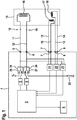
- FIG. 1 is the control device 1 for the resolver in the center, which may be integrated in the control device for a vehicle (not shown here). It has (or uses) a processor 2 which monitors the correct execution of all resolver functions to be controlled and also indicates malfunctions if necessary.
- control device 1 controls the power stages 3 and 4 for providing the sinusoidal exciter signal for the excitation coil 16 of the resolver 15 at the first terminals 5 and 6.
- the signals of the sine coil 17 and the cosine coil 18, the represent instantaneous angular position of the measuring object (eg the shaft of the motor) to the control device 1 and can be processed by the software after conversion in the AD converters 21 and 22 as a digital signal.
- the resolver excitation lines 11 and 12 represent the connection from the first terminals of the control device 1 to the resolver 15, namely to its exciter coil 16. These lines are to be monitored for interruption, which is shown in FIG. 1 with the potential interruptions 10 is indicated. From the sine coil 17 and the cosine coil 18 of the resolver 15, the signal lines 13 and 14 go to the second terminals 7 and 8 of the control device 1.
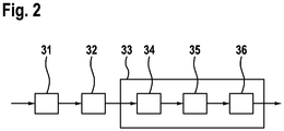
- the method for detecting an open resolver excitation line (10) begins with step 31 (cf. Fig. 2 ), in which the resolver signals are permanently measured at the second terminals 7 and 8 and evaluated by the processor 2 in such a way that the amplitude of the measurement signal is determined, which is the sum of the square of the signal U S of the sine coil 17 and the square of the signal U C of the cosine coil 18 results.
- This amplitude of the resolver signal U S 2 + U C 2 is compared with a first threshold value C S1 (step 32) and if this threshold value is undershot, ie if the resolver signal is absent, a diagnostic mode (step 33) is started.
- the excitation lines 11 and 12 and the excitation coil 16 are examined in more detail by trying to direct a DC current through them for a short time, for example for a field of excitation.
- power level 3 could also be controlled by the processor 2 in such a way that instead of the sinusoidal signal it outputs a time-constant voltage to ground, whereby the switch 26 would be saved.
- the terminal 6 is connected via a series resistor 25 R LE to ground.
- the resistance R LE of the series resistor 25 is large compared to the ohmic resistance R E of the excitation coil 16 is selected.
- the terminals 5 and 6 are connected via the excitation coil 16 low resistance to each other and therefore at almost the same potential, since the voltage drop mainly takes place at the resistor 25. If, however, there is an interruption, the voltage drop occurs between the first terminals 5 and 6 and can be measured there as a DC voltage difference.
- the processor 2 receives this information, the first terminals 5 and 6 are connected to the input of a third AD converter 23, the output of which is supplied to the processor 2.
- the voltage difference U E (t 1 ) is measured at the terminals 5 and 6 of the exciter line (method step 35 in FIG Fig. 2 ) at a plurality of times t i during at least one exciter period, namely during the time for which the terminals 5 and 6 of the exciter lines 11 and 12 are supplied with the DC voltage by means of the switching arrangement 24.
- the processor 2 determines from the measured values of the AD converter 23 the DC voltage component U E, Offs of the voltage difference U E (t L ) between the first terminals 5 and 6 (method step 36) and determines that an open exciter line 10 is present when the excitation period of DC voltage component U E, Offs is greater than a second threshold value C S2 .
- the necessary measures can be taken;
- the detection of the error is displayed or stored with a display and / or storage device 9, and the faulty line is named, for example, with its color or reference number.
- the excitation line has no interruption 10
- other causes for the absence of the resolver signal at the second terminals 7 and 8 can be researched.
Landscapes
- Physics & Mathematics (AREA)
- General Physics & Mathematics (AREA)
- Electromagnetism (AREA)
- Engineering & Computer Science (AREA)
- General Engineering & Computer Science (AREA)
- Transmission And Conversion Of Sensor Element Output (AREA)
- Testing Of Short-Circuits, Discontinuities, Leakage, Or Incorrect Line Connections (AREA)
Claims (9)
- Procédé pour détecter une ligne d'excitation de résolveur ouverte (10) comprenant les étapes suivantes consistant à :mesurer les tensions de signal (31) de la bobine sinus (17) et de la bobine cosinus (18) du résolveur ;comparer l'amplitude (32) du signal de résolveur calculé comme étant la somme des tensions au carré du signal à une première valeur seuil ;lancer un mode de diagnostic (33) lors des étapes suivantes, si l'amplitude calculée n'atteint pas la première valeur seuil :appliquer (34) une tension constante aux bornes (5, 6) de la ligne d'excitation (11, 12) par l'intermédiaire d'une résistance série (25) dont la valeur est élevée par comparaison à la résistance ohmique de la bobine d'excitation (16) pendant la durée d'au moins une période d'excitation ;mesurer la différence de tension (35) aux bornes (5, 6) de la ligne d'excitation à une pluralité d'instants pendant que la tension continue est appliquée ; etdéterminer la composante de tension continue (36) de la différence de tension ;déterminer (37) la présence d'une ligne d'excitation ouverte (10) si, pendant la période d'excitation, la composante de tension continue est supérieure à une deuxième valeur seuil.
- Procédé selon la revendication 1, dans lequel l'application (34) est effectuée par commutation d'une connexion à un potentiel de tension continue sur ladite une borne (5) de la bobine d'excitation et d'une connexion à la masse par l'intermédiaire de la résistance série (25) sur l'autre borne (6) de la bobine d'excitation.
- Procédé selon la revendication 1, dans lequel l'application (34) s'effectue par attaque de l'un des étages de sortie (3, 4) du circuit d'excitation avec une tension constante sur ladite une borne (5) de la bobine d'excitation et par commutation d'une connexion à la masse par l'intermédiaire de la résistance série (25) sur l'autre borne (6) de la bobine d'excitation.
- Procédé selon l'une des revendications 1 à 3, dans lequel la mesure de la différence de tension (35) aux bornes (5, 6) des lignes d'excitation (11, 12) s'effectue à une pluralité d'instants pendant au moins une période d'excitation.
- Procédé selon l'une des revendications 1 à 4, dans lequel la détermination de la composante de tension continue (35) s'effectue en fonction d'une somme des différences de tension maximale et minimale mesurées et, lors de la détermination des différences de tension maximale et minimale mesurées, il est tenu compte des points de mesure tant qu'une tension continue est présente.
- Procédé selon l'une des revendications 1 à 4, dans lequel les instants sont équidistants, la détermination de la composante de tension continue (35) s'effectue en fonction de la valeur moyenne des différences de tension mesurées pendant lesquelles une tension continue est présente et dans lequel les différences de tension sont déterminées au cours d'une période d'excitation ou d'un multiple de celle-ci.
- Circuit pour détecter une ligne d'excitation de résolveur ouverte (10), comprenant :un dispositif de commande (1) comportant un processeur (2), des étages de puissance (3, 4) et des premières bornes (5, 6) destinées à fournir des signaux sur les lignes d'excitation (11, 12) à la bobine d'excitation (16) du résolveur (15) et des deuxièmes bornes (7, 8) destinées à raccorder les lignes de signaux (13, 14) destinées aux signaux des bobines sinus et cosinus (17, 18) ;deux convertisseurs AD (21, 22) qui sont raccordés aux deuxièmes bornes (7, 8) du dispositif de commande (1) sur les lignes de signaux (13, 14) et dont les sorties peuvent être lues et évaluées par le processeur (2), dans lequel le processeur (2) est conçu pour mettre en oeuvre les étapes du procédé selon la revendication 1 ;les lignes d'excitation de résolveur (11, 12) à diagnostiquer, qui couplent les premières bornes (5, 6) à la bobine d'excitation (16) du résolveur (15) ; etdes lignes de signaux (13, 14) destinées au signaux sinus et cosinus fournis par le résolveur (15), qui couplent le résolveur (15) à des deuxièmes bornes (7, 8) du dispositif de commande (1) ;un dispositif de commutation électronique (24) commandé par le processeur (2) pour appliquer temporairement une tension continue aux premières bornes (5, 6) destinées au signal d'excitation par l'intermédiaire d'une résistance série (25) ;un troisième convertisseur AD (23) qui est raccordé aux premières bornes (5, 6) du dispositif de commande (1) et dont la sortie peut être lue et évaluée par le processeur (2) ; etun dispositif d'affichage et/ou de stockage (9) destiné à afficher et/ou stocker les informations identifiées par le processeur (2), qui comprennent la détection positive d'une ligne ouverte (10) de la bobine d'excitation (16) du résolveur.
- Circuit selon la revendication 7, dans lequel le dispositif de commutation électronique (24) comprend un commutateur (27) par l'intermédiaire duquel une borne (6) destinée à la ligne d'excitation (11) peut être temporairement commutée à la masse par l'intermédiaire d'une résistance série (25).
- Circuit selon la revendication 7 ou 8, dans lequel le dispositif de commutation électronique (24) comprend un commutateur (26) par l'intermédiaire duquel une tension continue par rapport à la masse peut être temporairement appliquée à une borne (5) de la ligne d'excitation (11).
Applications Claiming Priority (2)
| Application Number | Priority Date | Filing Date | Title |
|---|---|---|---|
| DE102015211224.1A DE102015211224A1 (de) | 2015-06-18 | 2015-06-18 | Verfahren und Schaltung zum Erkennen einer offenen Resolver-Erregerleitung |
| PCT/EP2016/062852 WO2016202631A1 (fr) | 2015-06-18 | 2016-06-07 | Procédé et circuit pour détecter une ligne d'excitation ouverte d'un résolveur |
Publications (2)
| Publication Number | Publication Date |
|---|---|
| EP3311107A1 EP3311107A1 (fr) | 2018-04-25 |
| EP3311107B1 true EP3311107B1 (fr) | 2019-04-24 |
Family
ID=56132902
Family Applications (1)
| Application Number | Title | Priority Date | Filing Date |
|---|---|---|---|
| EP16729519.5A Active EP3311107B1 (fr) | 2015-06-18 | 2016-06-07 | Procédé et circuit pour détecter une ligne d'excitation ouverte d'un résolveur |
Country Status (5)
| Country | Link |
|---|---|
| US (1) | US10495684B2 (fr) |
| EP (1) | EP3311107B1 (fr) |
| CN (1) | CN107735651B (fr) |
| DE (1) | DE102015211224A1 (fr) |
| WO (1) | WO2016202631A1 (fr) |
Families Citing this family (2)
| Publication number | Priority date | Publication date | Assignee | Title |
|---|---|---|---|---|
| CN110895131A (zh) * | 2018-09-12 | 2020-03-20 | 广州汽车集团股份有限公司 | 一种旋转变压器的激励信号和响应信号的监控方法和系统 |
| DE102019200318A1 (de) * | 2019-01-11 | 2020-07-16 | Zf Friedrichshafen Ag | Resolverschaltung |
Family Cites Families (24)
| Publication number | Priority date | Publication date | Assignee | Title |
|---|---|---|---|---|
| JPH09113205A (ja) * | 1995-10-19 | 1997-05-02 | Denso Corp | レゾルバ励磁装置 |
| JP3460587B2 (ja) * | 1998-07-21 | 2003-10-27 | トヨタ自動車株式会社 | 回転角検出装置の異常を検出する異常検出装置 |
| US6426712B1 (en) * | 2000-11-16 | 2002-07-30 | Analog Devices, Inc. | Fault-signal generators and methods for resolver systems |
| DE10221878A1 (de) * | 2001-06-01 | 2003-01-16 | Omron Corp Kyoto | Berührender Versetzungsdetektor und -sensor |
| JP2005024493A (ja) * | 2003-07-02 | 2005-01-27 | Nissan Motor Co Ltd | レゾルバの異常検出装置 |
| JP4521258B2 (ja) * | 2004-01-28 | 2010-08-11 | 日立オートモティブシステムズ株式会社 | レゾルバ/デジタル変換器及びこれを用いた制御システム |
| JP4475642B2 (ja) * | 2004-06-22 | 2010-06-09 | 株式会社ジェイテクト | レゾルバ異常検出装置及びそれを用いた車両用伝達比可変操舵装置 |
| US7288933B2 (en) * | 2005-12-22 | 2007-10-30 | Bell Helicopter Textron, Inc. | Position detecting system that self-monitors for connectivity faults |
| JP5011824B2 (ja) * | 2006-05-31 | 2012-08-29 | 株式会社ジェイテクト | 異常判定装置 |
| JP5045407B2 (ja) * | 2007-12-07 | 2012-10-10 | 株式会社ジェイテクト | レゾルバの異常検出装置および電気式動力舵取装置 |
| JP4929189B2 (ja) * | 2008-01-09 | 2012-05-09 | 日立オートモティブシステムズ株式会社 | レゾルバ異常検出回路 |
| JP5028294B2 (ja) * | 2008-02-14 | 2012-09-19 | 日立オートモティブシステムズ株式会社 | レゾルバの異常検出装置 |
| DE102009020431A1 (de) | 2008-05-13 | 2009-11-19 | Continental Teves Ag & Co. Ohg | Sensoreinrichtung und Fehlererkennungsverfahren für elektronische Schaltungen in Kraftfahrzeugen |
| JP2011089935A (ja) * | 2009-10-23 | 2011-05-06 | Toyota Motor Corp | レゾルバ異常検出装置 |
| KR101039676B1 (ko) * | 2009-11-04 | 2011-06-09 | 현대자동차주식회사 | 하이브리드 차량의 레졸버 단락 및 단선 감지용 회로 및 이를 이용한 레졸버 단락 및 단선 감지 방법 |
| DE102009046925A1 (de) * | 2009-11-20 | 2011-05-26 | Lenze Automation Gmbh | Verfahren, Vorrichtung und System zum Überwachen des Bestimmens eines Rotorwinkels einer rotierenden Welle mittels eines Resolvers |
| JP5051404B2 (ja) | 2010-08-25 | 2012-10-17 | トヨタ自動車株式会社 | トルク検出装置 |
| JP2012098188A (ja) | 2010-11-02 | 2012-05-24 | Denso Corp | 回転角検出システムの異常診断装置 |
| JP5494969B2 (ja) * | 2010-11-04 | 2014-05-21 | 株式会社デンソー | 回転角検出システムの異常診断装置 |
| CN102656432B (zh) * | 2010-12-24 | 2014-07-02 | 丰田自动车株式会社 | 扭矩检测装置 |
| DE102011078583A1 (de) | 2011-07-04 | 2013-01-10 | Robert Bosch Gmbh | Auswertung von Resolver-Sensorsignalen |
| JP2015187560A (ja) * | 2014-03-26 | 2015-10-29 | トヨタ自動車株式会社 | レゾルバ励磁回路 |
| DE102015211232A1 (de) * | 2015-06-18 | 2016-12-22 | Robert Bosch Gmbh | Verfahren und Schaltung zum Erkennen einer offenen Leitung der Sinus-/Kosinus-Empfängerspule eines Resolvers |
| DE102015211214A1 (de) * | 2015-06-18 | 2016-12-22 | Robert Bosch Gmbh | Verfahren und Schaltung zum Erkennen eines Kurzschlusses einer Resolver-Erregerleitung nach Masse oder zur Betriebsspannung |
-
2015
- 2015-06-18 DE DE102015211224.1A patent/DE102015211224A1/de not_active Withdrawn
-
2016
- 2016-06-07 WO PCT/EP2016/062852 patent/WO2016202631A1/fr not_active Ceased
- 2016-06-07 US US15/737,533 patent/US10495684B2/en active Active
- 2016-06-07 CN CN201680035718.1A patent/CN107735651B/zh active Active
- 2016-06-07 EP EP16729519.5A patent/EP3311107B1/fr active Active
Non-Patent Citations (1)
| Title |
|---|
| None * |
Also Published As
| Publication number | Publication date |
|---|---|
| US20180172757A1 (en) | 2018-06-21 |
| DE102015211224A1 (de) | 2016-12-22 |
| EP3311107A1 (fr) | 2018-04-25 |
| WO2016202631A1 (fr) | 2016-12-22 |
| US10495684B2 (en) | 2019-12-03 |
| CN107735651B (zh) | 2020-07-07 |
| CN107735651A (zh) | 2018-02-23 |
Similar Documents
| Publication | Publication Date | Title |
|---|---|---|
| EP3311115B1 (fr) | Procédé et circuit pour détecter une ligne ouverte de la bobine réceptrice sinus/cosinus d'un résolveur | |
| DE102017127799A1 (de) | Fehlertolerante messung von phasenströmen für motorsteuerungssysteme | |
| EP3660531A1 (fr) | Méthode et circuit de vérification de la plausibilité du résultat de la mesure d'un capteur de courant | |
| EP3311106B1 (fr) | Procédé et circuit pour détecter un court-circuit de la bobine réceptrice sinus/cosinus d'un résolveur | |
| EP2391902B1 (fr) | Procédé de fonctionnement d'un moteur sans balais | |
| EP3311107B1 (fr) | Procédé et circuit pour détecter une ligne d'excitation ouverte d'un résolveur | |
| EP3311114B1 (fr) | Procédé et circuit pour détecter un court-circuit d'une ligne d'excitation de résolveur vers la masse ou une tension de service | |
| EP3532857B1 (fr) | Dispositif et procédé pour le diagnostic de la détection d'un courant électrique polyphasé | |
| DE102019205561A1 (de) | Verfahren zur Diagnose eines Elektromotors | |
| DE102012223581A1 (de) | Vorrichtung und Verfahren zum Überwachen von Signalpegeln | |
| EP4016835B1 (fr) | Procédé de détermination de la position angulaire du rotor d'un moteur synchrone alimenté par un inverseur et dispositif de mise en oeuvre du procédé | |
| DE102018002188A1 (de) | Verfahren zum Prüfen eines Antriebs und Antrieb | |
| EP4187208B1 (fr) | Dispositif et procédé de détection de position avec détection de défaut avec un capteur de position | |
| EP3529890B1 (fr) | Système de réglage d'une machine synchrone et procédé pour faire fonctionner une machine synchrone | |
| DE102019212900A1 (de) | Erkennung von Defekten in Gleichrichter-Spannungsreglermodulen | |
| DE102012220843A1 (de) | Diagnose einer Drehfeldmaschine | |
| DE102019200318A1 (de) | Resolverschaltung | |
| DE102019107725A1 (de) | Vorrichtung und ein Verfahren zur Detektion eines Windungsschlusses einer Statorspule | |
| DE102013213053A1 (de) | Drehwinkelsensorvorrichtung mit redundanten Sensoreinheiten | |
| DE102021117082A1 (de) | Elektronische Schaltungsanordnung zum Bestimmen eines Offsetwinkels für eine elektrische Maschine mit Erfassung von Nulldurchgängen | |
| EP3297153A1 (fr) | Procédé et dispositif de détermination d'une position de rotor d'un rotor d'une machine électrique à commutation électronique | |
| EP3479468A1 (fr) | Procédé et dispositif pour vérifier une ligne de raccordement à plusieurs phases et circuit en pont pour un moteur électrique à plusieurs phases | |
| DE102017204987A1 (de) | Verfahren und Vorrichtung zum Bestimmen einer Drehung eines Geberrads, und elektrische Maschine |
Legal Events
| Date | Code | Title | Description |
|---|---|---|---|
| STAA | Information on the status of an ep patent application or granted ep patent |
Free format text: STATUS: THE INTERNATIONAL PUBLICATION HAS BEEN MADE |
|
| PUAI | Public reference made under article 153(3) epc to a published international application that has entered the european phase |
Free format text: ORIGINAL CODE: 0009012 |
|
| STAA | Information on the status of an ep patent application or granted ep patent |
Free format text: STATUS: REQUEST FOR EXAMINATION WAS MADE |
|
| 17P | Request for examination filed |
Effective date: 20180118 |
|
| AK | Designated contracting states |
Kind code of ref document: A1 Designated state(s): AL AT BE BG CH CY CZ DE DK EE ES FI FR GB GR HR HU IE IS IT LI LT LU LV MC MK MT NL NO PL PT RO RS SE SI SK SM TR |
|
| AX | Request for extension of the european patent |
Extension state: BA ME |
|
| DAV | Request for validation of the european patent (deleted) | ||
| DAX | Request for extension of the european patent (deleted) | ||
| REG | Reference to a national code |
Ref country code: DE Ref legal event code: R079 Ref document number: 502016004346 Country of ref document: DE Free format text: PREVIOUS MAIN CLASS: G01B0007300000 Ipc: G01D0018000000 |
|
| GRAP | Despatch of communication of intention to grant a patent |
Free format text: ORIGINAL CODE: EPIDOSNIGR1 |
|
| STAA | Information on the status of an ep patent application or granted ep patent |
Free format text: STATUS: GRANT OF PATENT IS INTENDED |
|
| RIC1 | Information provided on ipc code assigned before grant |
Ipc: G01B 7/30 20060101ALN20181204BHEP Ipc: G01R 31/28 20060101ALI20181204BHEP Ipc: G01D 18/00 20060101AFI20181204BHEP Ipc: G01D 5/20 20060101ALI20181204BHEP Ipc: G01R 31/02 20060101ALI20181204BHEP |
|
| INTG | Intention to grant announced |
Effective date: 20190104 |
|
| GRAS | Grant fee paid |
Free format text: ORIGINAL CODE: EPIDOSNIGR3 |
|
| GRAA | (expected) grant |
Free format text: ORIGINAL CODE: 0009210 |
|
| STAA | Information on the status of an ep patent application or granted ep patent |
Free format text: STATUS: THE PATENT HAS BEEN GRANTED |
|
| AK | Designated contracting states |
Kind code of ref document: B1 Designated state(s): AL AT BE BG CH CY CZ DE DK EE ES FI FR GB GR HR HU IE IS IT LI LT LU LV MC MK MT NL NO PL PT RO RS SE SI SK SM TR |
|
| REG | Reference to a national code |
Ref country code: GB Ref legal event code: FG4D Free format text: NOT ENGLISH |
|
| REG | Reference to a national code |
Ref country code: CH Ref legal event code: EP |
|
| REG | Reference to a national code |
Ref country code: AT Ref legal event code: REF Ref document number: 1124683 Country of ref document: AT Kind code of ref document: T Effective date: 20190515 Ref country code: IE Ref legal event code: FG4D Free format text: LANGUAGE OF EP DOCUMENT: GERMAN |
|
| REG | Reference to a national code |
Ref country code: DE Ref legal event code: R096 Ref document number: 502016004346 Country of ref document: DE |
|
| REG | Reference to a national code |
Ref country code: NL Ref legal event code: MP Effective date: 20190424 |
|
| REG | Reference to a national code |
Ref country code: LT Ref legal event code: MG4D |
|
| PG25 | Lapsed in a contracting state [announced via postgrant information from national office to epo] |
Ref country code: NL Free format text: LAPSE BECAUSE OF FAILURE TO SUBMIT A TRANSLATION OF THE DESCRIPTION OR TO PAY THE FEE WITHIN THE PRESCRIBED TIME-LIMIT Effective date: 20190424 |
|
| PG25 | Lapsed in a contracting state [announced via postgrant information from national office to epo] |
Ref country code: LT Free format text: LAPSE BECAUSE OF FAILURE TO SUBMIT A TRANSLATION OF THE DESCRIPTION OR TO PAY THE FEE WITHIN THE PRESCRIBED TIME-LIMIT Effective date: 20190424 Ref country code: FI Free format text: LAPSE BECAUSE OF FAILURE TO SUBMIT A TRANSLATION OF THE DESCRIPTION OR TO PAY THE FEE WITHIN THE PRESCRIBED TIME-LIMIT Effective date: 20190424 Ref country code: SE Free format text: LAPSE BECAUSE OF FAILURE TO SUBMIT A TRANSLATION OF THE DESCRIPTION OR TO PAY THE FEE WITHIN THE PRESCRIBED TIME-LIMIT Effective date: 20190424 Ref country code: NO Free format text: LAPSE BECAUSE OF FAILURE TO SUBMIT A TRANSLATION OF THE DESCRIPTION OR TO PAY THE FEE WITHIN THE PRESCRIBED TIME-LIMIT Effective date: 20190724 Ref country code: HR Free format text: LAPSE BECAUSE OF FAILURE TO SUBMIT A TRANSLATION OF THE DESCRIPTION OR TO PAY THE FEE WITHIN THE PRESCRIBED TIME-LIMIT Effective date: 20190424 Ref country code: PT Free format text: LAPSE BECAUSE OF FAILURE TO SUBMIT A TRANSLATION OF THE DESCRIPTION OR TO PAY THE FEE WITHIN THE PRESCRIBED TIME-LIMIT Effective date: 20190824 Ref country code: ES Free format text: LAPSE BECAUSE OF FAILURE TO SUBMIT A TRANSLATION OF THE DESCRIPTION OR TO PAY THE FEE WITHIN THE PRESCRIBED TIME-LIMIT Effective date: 20190424 Ref country code: AL Free format text: LAPSE BECAUSE OF FAILURE TO SUBMIT A TRANSLATION OF THE DESCRIPTION OR TO PAY THE FEE WITHIN THE PRESCRIBED TIME-LIMIT Effective date: 20190424 |
|
| PG25 | Lapsed in a contracting state [announced via postgrant information from national office to epo] |
Ref country code: GR Free format text: LAPSE BECAUSE OF FAILURE TO SUBMIT A TRANSLATION OF THE DESCRIPTION OR TO PAY THE FEE WITHIN THE PRESCRIBED TIME-LIMIT Effective date: 20190725 Ref country code: BG Free format text: LAPSE BECAUSE OF FAILURE TO SUBMIT A TRANSLATION OF THE DESCRIPTION OR TO PAY THE FEE WITHIN THE PRESCRIBED TIME-LIMIT Effective date: 20190724 Ref country code: RS Free format text: LAPSE BECAUSE OF FAILURE TO SUBMIT A TRANSLATION OF THE DESCRIPTION OR TO PAY THE FEE WITHIN THE PRESCRIBED TIME-LIMIT Effective date: 20190424 Ref country code: LV Free format text: LAPSE BECAUSE OF FAILURE TO SUBMIT A TRANSLATION OF THE DESCRIPTION OR TO PAY THE FEE WITHIN THE PRESCRIBED TIME-LIMIT Effective date: 20190424 Ref country code: PL Free format text: LAPSE BECAUSE OF FAILURE TO SUBMIT A TRANSLATION OF THE DESCRIPTION OR TO PAY THE FEE WITHIN THE PRESCRIBED TIME-LIMIT Effective date: 20190424 |
|
| PG25 | Lapsed in a contracting state [announced via postgrant information from national office to epo] |
Ref country code: IS Free format text: LAPSE BECAUSE OF FAILURE TO SUBMIT A TRANSLATION OF THE DESCRIPTION OR TO PAY THE FEE WITHIN THE PRESCRIBED TIME-LIMIT Effective date: 20190824 |
|
| REG | Reference to a national code |
Ref country code: DE Ref legal event code: R097 Ref document number: 502016004346 Country of ref document: DE |
|
| PG25 | Lapsed in a contracting state [announced via postgrant information from national office to epo] |
Ref country code: EE Free format text: LAPSE BECAUSE OF FAILURE TO SUBMIT A TRANSLATION OF THE DESCRIPTION OR TO PAY THE FEE WITHIN THE PRESCRIBED TIME-LIMIT Effective date: 20190424 Ref country code: DK Free format text: LAPSE BECAUSE OF FAILURE TO SUBMIT A TRANSLATION OF THE DESCRIPTION OR TO PAY THE FEE WITHIN THE PRESCRIBED TIME-LIMIT Effective date: 20190424 Ref country code: SK Free format text: LAPSE BECAUSE OF FAILURE TO SUBMIT A TRANSLATION OF THE DESCRIPTION OR TO PAY THE FEE WITHIN THE PRESCRIBED TIME-LIMIT Effective date: 20190424 Ref country code: MC Free format text: LAPSE BECAUSE OF FAILURE TO SUBMIT A TRANSLATION OF THE DESCRIPTION OR TO PAY THE FEE WITHIN THE PRESCRIBED TIME-LIMIT Effective date: 20190424 Ref country code: CZ Free format text: LAPSE BECAUSE OF FAILURE TO SUBMIT A TRANSLATION OF THE DESCRIPTION OR TO PAY THE FEE WITHIN THE PRESCRIBED TIME-LIMIT Effective date: 20190424 Ref country code: RO Free format text: LAPSE BECAUSE OF FAILURE TO SUBMIT A TRANSLATION OF THE DESCRIPTION OR TO PAY THE FEE WITHIN THE PRESCRIBED TIME-LIMIT Effective date: 20190424 |
|
| REG | Reference to a national code |
Ref country code: CH Ref legal event code: PL |
|
| PG25 | Lapsed in a contracting state [announced via postgrant information from national office to epo] |
Ref country code: SM Free format text: LAPSE BECAUSE OF FAILURE TO SUBMIT A TRANSLATION OF THE DESCRIPTION OR TO PAY THE FEE WITHIN THE PRESCRIBED TIME-LIMIT Effective date: 20190424 Ref country code: IT Free format text: LAPSE BECAUSE OF FAILURE TO SUBMIT A TRANSLATION OF THE DESCRIPTION OR TO PAY THE FEE WITHIN THE PRESCRIBED TIME-LIMIT Effective date: 20190424 |
|
| PLBE | No opposition filed within time limit |
Free format text: ORIGINAL CODE: 0009261 |
|
| STAA | Information on the status of an ep patent application or granted ep patent |
Free format text: STATUS: NO OPPOSITION FILED WITHIN TIME LIMIT |
|
| REG | Reference to a national code |
Ref country code: BE Ref legal event code: MM Effective date: 20190630 |
|
| PG25 | Lapsed in a contracting state [announced via postgrant information from national office to epo] |
Ref country code: TR Free format text: LAPSE BECAUSE OF FAILURE TO SUBMIT A TRANSLATION OF THE DESCRIPTION OR TO PAY THE FEE WITHIN THE PRESCRIBED TIME-LIMIT Effective date: 20190424 |
|
| 26N | No opposition filed |
Effective date: 20200127 |
|
| PG25 | Lapsed in a contracting state [announced via postgrant information from national office to epo] |
Ref country code: IE Free format text: LAPSE BECAUSE OF NON-PAYMENT OF DUE FEES Effective date: 20190607 |
|
| PG25 | Lapsed in a contracting state [announced via postgrant information from national office to epo] |
Ref country code: LI Free format text: LAPSE BECAUSE OF NON-PAYMENT OF DUE FEES Effective date: 20190630 Ref country code: BE Free format text: LAPSE BECAUSE OF NON-PAYMENT OF DUE FEES Effective date: 20190630 Ref country code: LU Free format text: LAPSE BECAUSE OF NON-PAYMENT OF DUE FEES Effective date: 20190607 Ref country code: SI Free format text: LAPSE BECAUSE OF FAILURE TO SUBMIT A TRANSLATION OF THE DESCRIPTION OR TO PAY THE FEE WITHIN THE PRESCRIBED TIME-LIMIT Effective date: 20190424 Ref country code: CH Free format text: LAPSE BECAUSE OF NON-PAYMENT OF DUE FEES Effective date: 20190630 |
|
| GBPC | Gb: european patent ceased through non-payment of renewal fee |
Effective date: 20200607 |
|
| PG25 | Lapsed in a contracting state [announced via postgrant information from national office to epo] |
Ref country code: GB Free format text: LAPSE BECAUSE OF NON-PAYMENT OF DUE FEES Effective date: 20200607 |
|
| PG25 | Lapsed in a contracting state [announced via postgrant information from national office to epo] |
Ref country code: CY Free format text: LAPSE BECAUSE OF FAILURE TO SUBMIT A TRANSLATION OF THE DESCRIPTION OR TO PAY THE FEE WITHIN THE PRESCRIBED TIME-LIMIT Effective date: 20190424 |
|
| PG25 | Lapsed in a contracting state [announced via postgrant information from national office to epo] |
Ref country code: MT Free format text: LAPSE BECAUSE OF FAILURE TO SUBMIT A TRANSLATION OF THE DESCRIPTION OR TO PAY THE FEE WITHIN THE PRESCRIBED TIME-LIMIT Effective date: 20190424 Ref country code: HU Free format text: LAPSE BECAUSE OF FAILURE TO SUBMIT A TRANSLATION OF THE DESCRIPTION OR TO PAY THE FEE WITHIN THE PRESCRIBED TIME-LIMIT; INVALID AB INITIO Effective date: 20160607 |
|
| PG25 | Lapsed in a contracting state [announced via postgrant information from national office to epo] |
Ref country code: MK Free format text: LAPSE BECAUSE OF FAILURE TO SUBMIT A TRANSLATION OF THE DESCRIPTION OR TO PAY THE FEE WITHIN THE PRESCRIBED TIME-LIMIT Effective date: 20190424 |
|
| REG | Reference to a national code |
Ref country code: AT Ref legal event code: MM01 Ref document number: 1124683 Country of ref document: AT Kind code of ref document: T Effective date: 20210607 |
|
| PG25 | Lapsed in a contracting state [announced via postgrant information from national office to epo] |
Ref country code: AT Free format text: LAPSE BECAUSE OF NON-PAYMENT OF DUE FEES Effective date: 20210607 |
|
| PGFP | Annual fee paid to national office [announced via postgrant information from national office to epo] |
Ref country code: FR Payment date: 20250627 Year of fee payment: 10 |
|
| PGFP | Annual fee paid to national office [announced via postgrant information from national office to epo] |
Ref country code: DE Payment date: 20250814 Year of fee payment: 10 |