EP3311138B1 - Bestimmung des absorptions- und streukoeffizienten mittels eines kalibrierten optischen reflexionssignals - Google Patents
Bestimmung des absorptions- und streukoeffizienten mittels eines kalibrierten optischen reflexionssignals Download PDFInfo
- Publication number
- EP3311138B1 EP3311138B1 EP16735922.3A EP16735922A EP3311138B1 EP 3311138 B1 EP3311138 B1 EP 3311138B1 EP 16735922 A EP16735922 A EP 16735922A EP 3311138 B1 EP3311138 B1 EP 3311138B1
- Authority
- EP
- European Patent Office
- Prior art keywords
- sample
- calibration
- distance
- backscattering
- optical
- Prior art date
- Legal status (The legal status is an assumption and is not a legal conclusion. Google has not performed a legal analysis and makes no representation as to the accuracy of the status listed.)
- Active
Links
Images




Classifications
-
- G—PHYSICS
- G01—MEASURING; TESTING
- G01N—INVESTIGATING OR ANALYSING MATERIALS BY DETERMINING THEIR CHEMICAL OR PHYSICAL PROPERTIES
- G01N21/00—Investigating or analysing materials by the use of optical means, i.e. using sub-millimetre waves, infrared, visible or ultraviolet light
- G01N21/17—Systems in which incident light is modified in accordance with the properties of the material investigated
- G01N21/25—Colour; Spectral properties, i.e. comparison of effect of material on the light at two or more different wavelengths or wavelength bands
- G01N21/27—Colour; Spectral properties, i.e. comparison of effect of material on the light at two or more different wavelengths or wavelength bands using photo-electric detection ; circuits for computing concentration
- G01N21/274—Calibration, base line adjustment, drift correction
-
- G—PHYSICS
- G01—MEASURING; TESTING
- G01N—INVESTIGATING OR ANALYSING MATERIALS BY DETERMINING THEIR CHEMICAL OR PHYSICAL PROPERTIES
- G01N21/00—Investigating or analysing materials by the use of optical means, i.e. using sub-millimetre waves, infrared, visible or ultraviolet light
- G01N21/17—Systems in which incident light is modified in accordance with the properties of the material investigated
- G01N21/47—Scattering, i.e. diffuse reflection
- G01N21/4795—Scattering, i.e. diffuse reflection spatially resolved investigating of object in scattering medium
-
- G—PHYSICS
- G01—MEASURING; TESTING
- G01N—INVESTIGATING OR ANALYSING MATERIALS BY DETERMINING THEIR CHEMICAL OR PHYSICAL PROPERTIES
- G01N21/00—Investigating or analysing materials by the use of optical means, i.e. using sub-millimetre waves, infrared, visible or ultraviolet light
- G01N21/17—Systems in which incident light is modified in accordance with the properties of the material investigated
- G01N21/47—Scattering, i.e. diffuse reflection
- G01N21/49—Scattering, i.e. diffuse reflection within a body or fluid
-
- G—PHYSICS
- G01—MEASURING; TESTING
- G01N—INVESTIGATING OR ANALYSING MATERIALS BY DETERMINING THEIR CHEMICAL OR PHYSICAL PROPERTIES
- G01N21/00—Investigating or analysing materials by the use of optical means, i.e. using sub-millimetre waves, infrared, visible or ultraviolet light
- G01N21/17—Systems in which incident light is modified in accordance with the properties of the material investigated
- G01N21/47—Scattering, i.e. diffuse reflection
- G01N2021/4735—Solid samples, e.g. paper, glass
Definitions
- the invention lies in the field of the characterization of samples, and in particular of biological samples, and more particularly of the skin.
- Optical measurements making it possible to characterize the optical properties of samples, are widespread. Mention may in particular be made of measurements based on the detection of a signal backscattered by a sample illuminated by a light beam. This is in particular Raman spectrometry, fluorescence imaging or diffuse reflectance spectrometry.
- DRS Diffuse Reflectance Spectroscopy
- this technique makes it possible, for example, to characterize the dermis or the epidermis, as described in the document EP 2762064 .
- This document describes a measurement probe intended to be applied against the skin.
- This probe comprises a central optical fiber, called an emission fiber, connected to a light source, and intended to direct a light beam towards a sample of skin.
- Optical fibers, arranged around the central fiber, called detection fibers collect an optical signal backscattered by the dermis, this optical signal then being detected by a photodetector.
- Means of spectral analysis of the optical signal make it possible to estimate parameters of the dermis, in particular the concentration of certain chromophores, for example oxyhemoglobin or deoxyhemoglobin and / or optical properties governing the path of photons in the dermis, in particular the reduced diffusion coefficient ⁇ s ' as well as the absorption coefficient ⁇ a .
- the probe comprises an illumination line, intended to illuminate the sample, comprising the light source and the emission optical fiber.
- the probe also comprises a detection line, intended to detect light backscattered by the sample, comprising the detection optical fibers and the photodetector.
- the properties of the illumination line and the detection line are taken into account thanks to a calibration step, allowing the determination of a calibration factor.
- the latter is obtained by performing a measurement on a calibration sample, the optical properties of which are known.
- This calibration factor designated by the term M std in this application, is then applied to the signal measured by the photodetector, designated by the term M skin .
- the determination of the optical properties is based on a priori knowledge of the sample and of a light scattering model in the analyzed sample, this model describing the change in the value of the scattering coefficient as a function of The wavelength.
- the determination of the optical properties is only quantitative for an analyzed sample whose diffusion coefficient reduces the same model as the calibration samples. It is understood that the need to be based on a model constitutes a constraining limitation. Such a method is not suitable for a complex sample, the a priori diffusion model of which is not known. Moreover, taking this model into account means that different estimates of an optical property, at different wavelengths, are not independent of each other, since they are linked by the model.
- An objective of the present invention is to improve the methods of the prior art, so as to determine the optical properties of a sample with increased precision.
- An object of the invention is a method for determining an optical property of a sample according to claim 1.
- This device may in particular include an optical system, configured to provide optical coupling between the photodetector and an elementary detection zone located at the surface of the sample, from which said backscattered radiation emanates.
- the figure 1 shows a first embodiment of a device 1 according to the invention. It comprises a light source 10, which, in this example, is a white light source marketed by Ocean Optics under the reference HL2000.
- the light source 10 comprises, in this example, an emission optical fiber 12, extending between a proximal end 14 and a distal end 16.
- the emission optical fiber 12 is adapted to collect light through a proximal end. 14 and in emitting a light beam 20 towards the sample via a distal end 16, said light beam then being directed towards the surface of a sample 50.
- the light source 10 is said to be fibered.
- the diameter of the emission optical fiber 12 is between 100 ⁇ m and 1 mm, and is for example equal to 500 ⁇ m.
- the device also comprises a plurality of detection optical fibers 22 1 , 22 2 , 22 3, ... 22 f ... 22 F , the index f being between 1 and F, F designating the number of optical fibers of detection in the device.
- F is a natural number generally between 1 and 100, and preferably between 5 and 50.
- Each detection fiber 22 1 , 22 2 , 22 3, .. 22 f, ... 22 F extends between one end proximal 24 1 , 24 2 , 24 3 , .. 24 f ... 24 F and a distal end 26 1 , 26 2 , ... 26 f ... 26 F.
- each detection optical fiber 22 is between 50 ⁇ m and 1 mm, and is for example equal to 100 ⁇ m.
- the proximal end 24 of each detection optical fiber 22 is able to be optically coupled to a photodetector 40.
- the distal end 26 1 , 26 2 , ... 26 F of each detection optical fiber 22 is able to collect respectively radiation 52 1 , 52 2 , ... 52 F backscattered by the sample 50, when the latter is exposed to the light beam 20.
- the photodetector 40 is able to detect each backscattered radiation 52 1 , 52 2 , ... 52 F so as to form a signal, called the backscatter signal (S 1 , S 2 , ... S N ) as described below.
- the Photodetector 40 may be a photodetector which is not spectrally resolved, for example a photodiode or a matrix photodetector of the CCD or CMOS type. In this example, it is a spectrophotometer, able to establish the wavelength spectrum of the radiation collected by a detection optical fiber 22 to which it is coupled. Those skilled in the art will choose a spectrometric photodetector when he favors good spectral resolution or a matrix photodetector when he favors good spatial resolution.
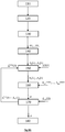
- the photodetector 40 is able to be connected to a processor 48, the latter being connected to a memory 49 comprising instructions, the latter being able to be executed by the processor 48, to implement the method shown in the diagrams. figures 4A or 4B , and described below. These instructions can be saved on a recording medium readable by a processor, such as hard disk, CDROM or other type of memory.
- the detection optical fibers 22 extend parallel to one another, parallel to a longitudinal axis Z around the transmission optical fiber 12. They are held fixed with respect to each other by a holding element 42. Their ends distals 26 are coplanar, and define, in this example, a detection plane 44.
- An optical fiber 13 called an excitation return fiber, connects the light source 10 to the photodetector 40. This optical fiber is useful for carrying out a source S measurement representing the intensity of the source, detailed later.
- each distal end 26 f of a detection optical fiber 22 f is placed, in a plane perpendicular to the longitudinal axis Z along which these fibers extend, at a distance d f from the light source 10 (c 'that is to say from the distal end 16 of the emission fiber 12), and, therefore, at a distance d f from the light beam 20 directed towards the sample 50.
- each detection optical fiber defines a curved surface, for example adapting to the curvature of the surface of the sample 50.
- the device comprises a photodetector 40, able to be coupled to the proximal end 24 f of each optical detection fiber 22 f .
- the photodetector is a spectrophotometer, able to determine the spectrum of radiation 52 1 ... 52 F backscattered by the sample when the latter is exposed to the light beam 20.
- the proximal ends 24 of each group of detection optical fibers, described above are grouped together and are, group by group, successively coupled to the photodetector 40 by means of an optical switch 41.
- the reference 52 designates radiation backscattered by the sample.
- the device also comprises an optical system 30, having a magnification factor G and an optical axis Z '.
- the optical axis Z ' coincides with the longitudinal axis Z along which the detection optical fibers extend, which constitutes a preferred configuration.
- the optical system 30 makes it possible to form an image of the surface of the sample 50 on the detection plane 44 formed by the distal ends 26 of each detection optical fiber 22, with a given magnification factor G .
- each distal end 26 1 , 26 2 ... 26 F is respectively conjugated to an elementary detection zone 28 1 , 28 2 , 28 f ... 28 F of the surface of the sample.
- each detection optical fiber 22 1 , 22 2, ... 22 F is able to collect respectively an elementary radiation 52 1 , 52 2 , 52 f ... 52 F backscattered by the sample, each elementary radiation 52 1 , 52 2 , ... 52 F emanating from an elementary detection zone 28 1 , 28 2 ... 28 F , on the surface of the sample.
- each of said distal ends 26 1 , 26 2 ... 26 F can be located in an image focal plane of the optical system 30, and combined with an elementary detection zone 28 1 , 28 2 ... 28 F located in the focal plane object of said optical system, at the surface of the sample.
- the distal end 16 of the emission fiber 12 is combined with an elementary illumination zone 18 on the surface of the sample.
- the elementary illumination zone constitutes the point of impact of the light beam 20 on the surface of the sample 50.
- the term elementary zone denotes a zone of shape delimited on the surface of the sample.
- Such an elementary zone is preferably punctual, that is to say that its diameter or its diagonal are less than 1 cm, and preferably less than 1 mm, or even less than 500 ⁇ m.
- An elementary detection zone can also take an annular shape, centered on the elementary illumination zone, by defining a ring, or an arc of a ring, circular or polygonal. The thickness of the ring is then preferably less than 1 cm.
- An elementary detection zone 28 can have any shape, provided that this zone elementary is delimited by a contour, and distant from an elementary illumination zone 18, the latter also possibly having any shape, but delimited and distinct from an elementary detection zone 28.
- An elementary illumination zone 18 is crossed by the light beam 20, propagating in the direction of the sample 50, while an elementary detection zone 28 f is crossed by a backscattered radiation 52 f , this radiation being produced by the backscattering, in the sample, of the light beam 20.
- the optical coupling, produced by the optical system 30, allows each detection fiber 22 f to collect the elementary backscattered radiation 52 f , the latter corresponding to the backscattered radiation passing through the elementary zone 28 f .
- the retaining element 42 can provide a rigid connection between the detection optical fibers 22 and the optical system 30, so as to maintain the detection plane 44, formed by the distal ends 26 of the detection optical fibers at a fixed distance from the detector. optical system 30.
- the distance D f is called the backscattering distance, because it corresponds to the distance, from the elementary illumination zone 18, at which the backscattered photons are collected. This corresponds to the distance between the elementary illumination zone 18 and an elementary detection zone 28f.
- the presence of the optical system 30 makes it possible to place the detection fibers 22 at a distance from the sample to be characterized, according to a so-called “remote” configuration.
- This distance is typically a few cm, for example between 1 and 30 cm.
- the device is similar to that shown in figure 1 , but it does not include an optical system 30.
- This variant corresponds to a measurement configuration known as the “contact” configuration.
- each detection optical fiber 22 f is able to collect backscattering radiation 52 f coming from an elementary detection zone 28 f , the latter being located at a backscattering distance D f from the elementary zone d illumination 18.
- the device due to the concentric arrangement of the detection fibers around the illumination fiber, described in connection with figure 2 , the device makes it possible to define N distinct backscattering distances D 1 ..D n ... D N , N being here equal to 6.
- Each backscattering distance D n corresponds to a plurality of backscattered radiations, coming from elementary detection zones different.
- the backscattering distance D 1 corresponds to the optical backscattering signals 52 1 , 52 2 , 52 3 , 52 4 , 52 5 and 52 6 .
- the detection fibers corresponding to the same group that is to say to the same backscattering distance, are coupled. Therefore, each backscattered radiation corresponding to the same backscattering distance D n (1 ⁇ n ⁇ 6) is simultaneously addressed to the photodetector 40, the latter producing a signal S n , called the backscatter signal, representative of one or more radiation backscattered at said backscatter distance D n .
- the calibration factor f n, pcalib ( ⁇ ) is a comparison between a quantity of interest, in this case a reflectance, modeled and this same quantity of interest measured by the device, on a calibration sample. This comparison usually takes the form of a ratio.
- this calibration factor is obtained on a sample, the optical properties of which p calib are known, but are not necessarily representative of the optical properties of the sample examined.
- the inventors have determined that the value of this calibration factor can change, depending on the optical properties of the sample.
- the calibration samples used contain a concentration of intralipid% IL respectively equal to 1%, 2% and 3% which gives them different diffusion properties, the absorption coefficient being equal to 0.4 cm -1 at 600 nm -1 .
- the calibration factors shown were determined by considering a backscattering distance of 1.1 mm, the device 1 being placed at a distance from each calibration sample, the distance between the sample and the detection optical fibers amounting to 20 cm.
- a calibration factor which is as representative as possible of the optical properties of the sample examined.
- these properties are not known.
- the desired optical properties are ⁇ a ( ⁇ ) and ⁇ ' s ( ⁇ ).
- the pair ( ⁇ a ( ⁇ ), ⁇ ' s ( ⁇ )) sought is the one exhibiting the smallest difference between the measured reflectance R n ( ⁇ ), at the wavelength ⁇ , and a modeled reflectance R not , ⁇ at , ⁇ s ′ model ⁇ for different values of ⁇ a ( ⁇ ) and ⁇ ' s ( ⁇ ), at said backscatter distance D n .
- the different modeled reflectance values R not , ⁇ at , ⁇ s model ⁇ are obtained, for a plurality of pairs of values ⁇ a , ⁇ s ' during a parameterization phase, by numerical simulation implementing a Monte-Carlo type method or by an analytical model.
- an analytical model can only be used beyond a certain backscatter distance. For a given backscattering distance D n , it is possible to establish a plurality of reflectances R not , ⁇ at , ⁇ s ′ model ⁇ modeled as a function of ⁇ a and ⁇ s '.
- the figure 6 gives an example of representation of such modeled reflectances, considering a backscattering distance D n equal to 700 ⁇ m and taking into account values of the absorption coefficient between 0 and 10 cm -1 , as well as values of the coefficient of reduced diffusion between 0 and 80 cm -1 .
- Steps 150 and 160 are implemented by the processor 48, previously programmed for this purpose, and whose input data are the measurements of the backscattering signals S n ( ⁇ ) carried out by the photodetector 40.
- Each calibration factor, as well as each value R not , p model ⁇ can be stored in a memory, for example memory 49, connected to processor 48.
- the notation f n, p ( ⁇ ) corresponds to a calibration factor corresponding to the optical properties p, to the backscattering distance D n , for the wavelength ⁇ .
- This calibration factor can be obtained using a measurement on a calibration sample, in which case it can also be denoted by f n, calibp ( ⁇ ), the index calibp referring to the calibration sample of optical properties p. It can also be determined by interpolation calculation, as described below.
- the iterative process is stopped after a predetermined number of iterations, or when the difference between optical properties p i , p i + 1 determined during step 160 of two successive iterations i and i + 1 is less at a predetermined threshold. We then go to step 180 for outputting the algorithm.
- the figure 4B represents a variant of this method, in which steps 110 to 180 are analogous to those explained in connection with the figure 4A .
- the device 1 prior to the implementation of this method, the device 1 is placed in front of a calibration sample whose optical properties p calib are known. Indeed, the inventors have observed that a calibration factor f n, p ( ⁇ ) is not stable over time, due to the evolution of the properties of the components constituting the illumination line and the line of illumination. detection. This can come from a normal development of these components, for example the wear of an optical fiber, or the aging of the source, or even a slight displacement of the optical system.
- the inventors implemented an update of the calibration factors f n, p, t 0 ( ⁇ ) determined at an instant t 0 and stored in memory. This is the subject of steps 100 to 106.
- Steps 100, 101, 102 and 103 are respectively analogous to steps 110, 120, 130 and 140, the only difference being that the sample analyzed is the calibration sample.
- the detection optical fibers 22 collect a plurality of backscattered radiations 52 1 * ... 52 F *, the exponent * designating the fact that a calibration sample is used.
- the photodetector 40 then forms as many backscattering signals S calib-1 ( ⁇ ) ... S calib-N ( ⁇ ) as there are different backscattering distances D 1 ... D N.
- step 104 makes it possible to obtain a reflectance R calib-n ( ⁇ ) , at each backscattering distance D n and for each wavelength ⁇ considered.
- step 105 a calibration factor f n, pcalib *, t ( ⁇ ) corresponding to the calibration sample is determined, according to equation 2.
- the indices t and t 0 refer respectively to the measurement instants t and t 0 .
- the exponent * represents a measurement performed on a calibration sample used to determine the refresh factor.
- the update factor k n, t ( ⁇ ) is essentially governed by the evolution of the backscattered signals S calib * -n, t 0 ( ⁇ ) and S calib * -n, t ( ⁇ ).
- the calibration sample used for determining the update factor, according to equations (4) and (4 '), can be any calibration sample.
- it is an easily transportable calibration sample, the optical properties of which are particularly stable, in particular between the instants t and t 0 .
- It may for example be a sample produced using a solid resin, the optical absorption and diffusion properties of which are respectively adjusted by adding India ink and diffusing particles of carbon dioxide. Titanium (TiO 2 ).
- the updating factor k n, t ( ⁇ ) is then implemented, in the form of a multiplicative term, in step 150 for determining a quantity of interest R n ( ⁇ ) from the backscattered signal S n ( ⁇ ).
- the expression (1) can then be replaced by the expression (1 '):
- R not ⁇ s not ⁇ - s ref ⁇ s source ⁇ ⁇ t ⁇ f not i ⁇ ⁇ k not , t ⁇
- test samples comprising a water base, and the optical absorption and diffusion properties of which are adjusted respectively by adding India ink and Intralipid.
- the optical properties p sought are the absorption coefficient ⁇ a and the reduced diffusion coefficient ⁇ s' .
- the figures 7A and 7B represent respective estimates of the reduced scattering coefficient and the absorption coefficient as a function of wavelength, during contact tests on a test sample whose optical properties are known: its absorption coefficient is equal at 1 cm -1 at 600nm, while its reduced diffusion coefficient, equivalent to a concentration of 1.5% intralipid, amounts to 22 cm -1 at 600 nm.
- each dotted curve corresponds to the theoretical value of the diffusion coefficient reduced by 4 calibration samples, as a function of the wavelength.
- Their reduced diffusion coefficients ⁇ s ', at 600 nm, are respectively 13.5 cm -1 , 20.3 cm -1 , 27 cm -1 and 40.6 cm -1 .
- These four calibration samples are respectively designated by “CF1%”, “CF1.5%”, “CF2%” and “CF3%”.
- These calibration samples are used to establish a calibration factor f n, p ( ⁇ ) , associated with the optical properties p of each sample.
- the test sample was illuminated by the light source 10, during which the backscattered signal S 2 ( ⁇ ).,. S 6 ( ⁇ ) corresponding respectively to 5 backscattering distances D 2 was detected. ... D 6 .
- the wavelength spectrum of each of these detected signals was carried out, in a spectral band between 470 nm and 880 nm.
- the reflectance of the test sample P 2 ( ⁇ ) ... P 6 ( ⁇ ), at the different backscattering distances was determined using expression (1).
- each calibration factor f n, p ( ⁇ ) associated with each calibration sample, so as to calculate 4 reflectance measurements.
- the dotted curve designated " ⁇ s'-test " corresponds to the reduced diffusion coefficient ⁇ s' ( ⁇ ) of the test sample. It represents the exact value of the reduced diffusion coefficient as a function of the wavelength.
- the curves in solid lines correspond to estimates of this coefficient, at different wavelengths. It appears that taking into account a calibration factor based on the CF3% calibration sample leads to an erroneous estimate of ⁇ s' ( ⁇ ).
- the estimates using a calibration factor established with the other calibration samples (CF1.5%, CF1% and CF2%) are more consistent with reality, the best estimate being obtained with the calibration factor established with the calibration sample CF1.5%.
- the dotted curve designated " ⁇ a-test" corresponds to the absorption coefficient ⁇ a ( ⁇ ) of the test sample. It represents the exact value of the absorption coefficient as a function of the wavelength.
- the curves in solid lines correspond to estimates of this coefficient, at different wavelengths, each estimate being carried out by considering a calibration factor f n , p ( ⁇ ) determined respectively with each calibration sample.
- estimates based on the CF3% sample lead to erroneous results, the best estimate being the one taking into account the CF1.5% calibration sample.
- the figures 7C and 7D respectively represent results similar to figures 7A and 7B , the device used comprising an optical system 30, allowing its use at a distance from the sample.
- the distal end of the detection optical fibers is placed 20 cm from the surface of the sample. It can be seen that taking into account a calibration factor representative of the optical properties of the sample examined very significantly improves the estimation of the absorption coefficient. More precisely, we note that taking into account a calibration factor based on different optical properties of the sample examined leads to significant errors in the estimation of the absorption coefficient, as shown by the curve CF3% of the figure 7D .
- the figures 8A, 8B and 8C, 8D represent estimates of the optical properties ( ⁇ s' ( ⁇ ) and ⁇ a ( ⁇ )) respectively according to the prior art and by implementing the invention, the device being applied in contact with four test samples.
- the actual values of the reduced diffusion coefficient of each test sample are shown in dotted lines on the figures 8A and 8C .
- the actual values of the absorption coefficient of each test sample are shown in dotted lines on the figures 8B and 8D .
- These 4 test samples, designated IL1%, IL1.5%, IL2%, IL3% are respectively identical to the calibration samples CF1%, CF1.5%, CF2% and CF3% previously described.
- the curves in solid lines correspond to estimates of the coefficients ⁇ s' ( ⁇ ) or ⁇ a ( ⁇ ) of each test sample.
- the figure 8A represents estimates of the reduced diffusion coefficient of each test sample.
- the same calibration factor, established using the CF1% calibration sample was used.
- the reduced diffusion coefficient is correctly estimated for the IL1% sample, since the method uses a calibration factor established with this same sample.
- the reduced diffusion coefficient of the IL1.5% sample is also determined correctly.
- the reduced diffusion coefficients of the IL2% and IL3% samples are not estimated with satisfactory precision.
- the figure 8C represents similar measurements, by implementing the algorithm described above, with, during the first iteration, the use of a calibration factor established using the IL1% calibration sample. Contrary to the results presented on the figure 8A , the reduced diffusion coefficient of each test sample was correctly estimated.
- the figure 8B represents estimates of the absorption coefficient of each test sample.
- the same calibration factor, established using the CF1% calibration sample was used.
- the figure 8D represents similar measurements, by implementing the algorithm described above, with, during the first iteration, the use of a calibration factor established using the calibration sample CF1%. The precision of the estimate is satisfactory in both cases, but the implementation of the algorithm increases this precision.
- the figures 9A, 9B, 9C and 9D represent tests similar to those reported respectively reported on the figures 8A, 8B, 8C and 8D , the only difference being that the device is used according to a “remote” configuration, and by implementing an optical focusing system, the distance between the end of each detection fiber and the sample being 20cm.
- the square root of the mean square error, ⁇ as defined above has also been estimated. The results are reported in Table 2 below.
- the white light source can be replaced by different light sources emitting in different spectral bands ⁇ 1 , ⁇ 2 ... ⁇ L.
- the illumination beam 20 can comprise, simultaneously or successively, different spectral bands ⁇ 1 , ⁇ 2 ... ⁇ L.
- the device may also include a light source, comprising a plurality of optical band-pass filters, able to be successively placed. next to the source. In this way, the illumination beam 20 successively comprises different spectral bands ⁇ 1 , A 2 ... ⁇ L.
- the light source is capable of forming, on the surface of the sample, an elementary illumination zone as defined above.
- the use of optical fibers to form the illumination beam is not necessary.
- a light source could be a laser source, or another light source, for example a light emitting diode.
- the light source can be coupled to an optical shaping system, allowing the formation of the light beam 20 and its projection on the surface of the sample in order to define the illumination elementary zone 18.
- the photodetector may be a photodiode, or a matrix photodetector of the CCD or CMOS type. Each pixel of the photodetector is then coupled to an elementary detection zone either by the optical system 30, or by being placed in contact with the surface of the sample, or optionally by means of optical fibers.
- the use of such a photodetector makes it possible to obtain a large number of different backscattering distances. It should be favored in applications requiring good spatial resolution.
- the light source is able to form an illumination beam 20, successively, in different spectral bands ⁇ 1 , ⁇ 2 ...
- such a photodetector can detect measuring a backscattering signal S n ( ⁇ ), successively , in each of the spectral bands.
- the optical property is then determined in each spectral band, independently of one another, by implementing the steps described above.
- the width of a spectral band can be less than 10 nm, so as to have a precise estimate of the evolution of the optical property considered as a function of the length. wave.
- the number N of backscattering distances can also vary. In general, this number must be greater than or equal to the number of optical properties to be determined.
- the invention can be implemented to characterize the surface optical properties of a sample. Applied to the skin, it allows for example the early detection of pathologies, the control of the vascularization or the perfusion of an active principle. It can be applied to any application, such as non-destructive testing, making it possible to estimate or follow the evolution of an optical property near the surface of a sample. It may for example be applications in the food industry, in order to control the quality or the composition of food.
Landscapes
- Physics & Mathematics (AREA)
- General Physics & Mathematics (AREA)
- Pathology (AREA)
- Life Sciences & Earth Sciences (AREA)
- Chemical & Material Sciences (AREA)
- Analytical Chemistry (AREA)
- Biochemistry (AREA)
- Health & Medical Sciences (AREA)
- Immunology (AREA)
- General Health & Medical Sciences (AREA)
- Engineering & Computer Science (AREA)
- Mathematical Physics (AREA)
- Theoretical Computer Science (AREA)
- Spectroscopy & Molecular Physics (AREA)
- Optics & Photonics (AREA)
- Investigating Or Analysing Materials By Optical Means (AREA)
Claims (12)
- Verfahren zur Bestimmung einer optischen Eigenschaft (p) einer Probe (50), umfassend die folgenden Schritte:i) Beleuchtung einer Oberfläche der Probe mithilfe eines Lichtstrahls (20), der von einer Lichtquelle (10) erzeugt wird, um auf der Oberfläche der Probe eine elementare Beleuchtungszone (18) zu bilden, die dem Teil der Oberfläche entspricht, die durch den Lichtstrahl beleuchtet wird;ii) Erfassung eines Rückstreusignals (S1(λ),...,SN(λ)) von der elementaren Beleuchtungszone mit einer Wellenlänge (λ), das für eine von der Probe rückgestreute Strahlung (521...52F) mit der Wellenlänge repräsentativ ist, mithilfe eines Fotodetektors (40) in einem Abstand (D1,..., DN), Rückstreuabstand genannt;iii) Auswahl eines Kalibrierfaktors
 iv) Anwendung des Kalibrierfaktors
 v) Bestimmung mindestens einer optischen Streu- oder Absorptionseigenschaft (p) der Probe mit der Wellenlänge mithilfe der interessierenden Größe;wobei das Verfahren dadurch gekennzeichnet ist, dass es umfasst:
vi) Wiederholung der Schritte iv) bis v) durch Aktualisieren des Kalibrierfaktors
und dadurch, dass der Kalibrierfaktor aktualisiert wird, indem eine Bibliothek verwendet wird, die Kalibrierfaktoren für verschiedene optische Eigenschaften (p) umfasst, wobei mindestens ein Kalibrierfaktor gemessen wird, indem ein Verhältnis gebildet wird zwischen:- einer Schätzung einer Größe - einem Maß der Größe (R calib-n (λ) mithilfe eines Rückstreusignals (Scalib-n (λ), das vom Fotodetektor (40) mit der Wellenlänge detektiert wird, wobei die Kalibrierprobe durch den Lichtstrahl (20) beleuchtet wird.
 - Verfahren nach Anspruch 1, wobei mindestens ein Kalibrierfaktor, der in Abhängigkeit von der optischen Eigenschaft (p) ausgewählt wird, durch Interpolation ausgehend von zwei gemessenen Kalibrierfaktoren (fn,p(λ),fn,p'(λ)) mit der Wellenlänge bestimmt wird, wobei die gemessenen Kalibrierfaktoren erhalten werden, indem jeweils zwei Kalibrierproben verwendet werden, deren optische Eigenschaften (p, p') unterschiedlich sind.
- Verfahren nach einem der vorhergehenden Ansprüche, wobei die optische Eigenschaft (p), die für die Aktualisierung des Kalibrierfaktors berücksichtigt wird, eine optische Streueigenschaft ist.
- Verfahren nach Anspruch 3, wobei die optische Eigenschaft ausgewählt wird aus:- einem Streukoeffizienten (µs)- einem reduzierten Streukoeffizienten (µs').
- Verfahren nach einem der vorhergehenden Ansprüche, wobei der Schritt iv) die Anwendung eines Reaktualisierungsfaktors kn,t (λ) umfasst, der bestimmt wird durch:▪ Messen eines Rückstreusignals (Sn,pcalib,t (λ)), das eine rückgestreute Strahlung repräsentiert, die von der Oberfläche der Kalibrierprobe ausgeht, im Rückstreuabstand (Dn) der elementaren Beleuchtungszone der Kalibrierprobe, wobei die Kalibrierprobe durch den Lichtstrahl (20) beleuchtet wird;▪ Vergleich des Rückstreusignals (Sn,pcalib,t (λ)), das zum Zeitpunkt t gemessen wird, mit einem Signal (S n,pcalib,t0(λ)), das unter denselben Bedingungen zu einem früheren Zeitpunkt to als dem Zeitpunkt t gemessen wurde,so dass jeder Kalibrierfaktor, der dem Rückstreuabstand entspricht, durch den Reaktualisierungsfaktor reaktualisiert wird, wobei der Reaktualisierungfaktor ausgehend von einer einzigen Kalibrierprobe bestimmt wird.
- Verfahren nach einem der vorhergehenden Ansprüche, wobei in Schritt v) die Bestimmung der optischen Eigenschaft (p) einen Vergleich zwischen Folgendem umfasst:- einer interessierende Größe (R1(λ),...,PN(λ)),- einer Vielzahl von Schätzungen der interessierenden Größe (R1,p model,..., RN,p model), wobei jede Schätzung unter Berücksichtigung eines vorbestimmten Werts der optischen Eigenschaft (p) durchgeführt wird.
- Verfahren nach einem der vorhergehenden Ansprüche, wobei jedes Rückstreusignal (S1(λ),...,SN(λ)) mit einer Vielzahl von Wellenlängen erfasst wird, so dass die interessierende Größe (R1(λ),...,RN(λ)) und der Kalibrierfaktor

- Verfahren nach einem der vorhergehenden Ansprüche, wobei die interessierende Größe (Rn(λ)), die mit einem Rückstreuabstand (Dn) verbunden ist, durch Anwendung eines Verhältnisses zwischen der Stärke eines Rückstreusignals (Sn(λ)), die dem Rückstreuabstand (Dn) entspricht, und der Intensität (Ssource) des Lichtstrahls (20), gemessen durch den Fotodetektor (40), erhalten wird, in welchem Fall die interessierende Größe ein Reflexionsvermögen ist.
- Verfahren nach einem der vorhergehenden Ansprüche, wobei in Schritt v) verschiedene Werte der interessierenden Größe betrachtet werden, wobei jeder Wert einem anderen Rückstreuabstand entspricht.
- Verfahren nach einem der vorhergehenden Ansprüche, wobei die untersuchte Probe ein menschliches, tierisches, pflanzliches Gewebe oder ein Lebensmittel ist.
- Vorrichtung zur Messung eines von einer Probe erzeugten optischen Signals, umfassend:- eine Lichtquelle (10), die dazu fähig ist, einen Lichtstrahl (20) auf eine Oberfläche der Probe (50) zu emittieren, um auf der Oberfläche eine elementare Beleuchtungszone (18) zu bilden,- einen Fotodetektor (40), der dazu fähig ist, in einem Abstand (D1,..., DN), Rückstreuabstand genannt, ein Rückstreusignal (S1(λ),..., SN(λ)) zu erfassen, das für eine von der Probe rückgestreute Strahlung (521...52F) repräsentativ ist;wobei die Vorrichtung dadurch gekennzeichnet ist, dass sie auch Folgendes umfasst:- einen Prozessor (48), der dazu fähig ist, die Schritte iii) bis vi) des Verfahrens als Gegenstand eines der Ansprüche 1 bis 10 umzusetzen.
- Vorrichtung nach Anspruch 11, die auch ein optisches System (30) umfasst, das dazu konfiguriert ist, eine optische Kopplung zwischen dem Fotodetektor (40) und einer auf der Oberfläche der Probe befindlichen elementaren Detektionszone (28, 28n) herzustellen, von der die rückgestreute Strahlung (521...52F) ausgeht.
Applications Claiming Priority (2)
| Application Number | Priority Date | Filing Date | Title |
|---|---|---|---|
| FR1555657A FR3037653B1 (fr) | 2015-06-19 | 2015-06-19 | Procede de traitement d’un signal de retrodiffusion |
| PCT/FR2016/051501 WO2016203183A1 (fr) | 2015-06-19 | 2016-06-20 | Determination de coefficient d'absorption et de diffusion a l'aide d'un signal optique de relfexion calibre |
Publications (2)
| Publication Number | Publication Date |
|---|---|
| EP3311138A1 EP3311138A1 (de) | 2018-04-25 |
| EP3311138B1 true EP3311138B1 (de) | 2021-07-07 |
Family
ID=53801078
Family Applications (1)
| Application Number | Title | Priority Date | Filing Date |
|---|---|---|---|
| EP16735922.3A Active EP3311138B1 (de) | 2015-06-19 | 2016-06-20 | Bestimmung des absorptions- und streukoeffizienten mittels eines kalibrierten optischen reflexionssignals |
Country Status (4)
| Country | Link |
|---|---|
| US (1) | US20180180535A1 (de) |
| EP (1) | EP3311138B1 (de) |
| FR (1) | FR3037653B1 (de) |
| WO (1) | WO2016203183A1 (de) |
Families Citing this family (4)
| Publication number | Priority date | Publication date | Assignee | Title |
|---|---|---|---|---|
| DE102020201637A1 (de) * | 2020-02-11 | 2021-08-12 | Ibeo Automotive Systems GmbH | Verfahren zur Analyse von Rückstreuungs-Histogrammdaten bei einem optischen Pulslaufzeit-Verfahren und Vorrichtung zur Datenverarbeitung |
| GB202009640D0 (en) * | 2020-06-24 | 2020-08-05 | Ams Sensors Singapore Pte Ltd | Optical detection system calibration |
| FR3118408B1 (fr) | 2020-12-29 | 2022-11-11 | Commissariat Energie Atomique | Procédé d’analyse d’un échantillon par mesure résolue en temps de l’intensité de photons rétrodiffusés |
| FR3144285B1 (fr) | 2022-12-27 | 2024-11-08 | Commissariat Energie Atomique | Procédé d ’analyse d’un objet comportant plusieurs couches superposées, par mesures de réflectance optique. |
Family Cites Families (2)
| Publication number | Priority date | Publication date | Assignee | Title |
|---|---|---|---|---|
| JP5109482B2 (ja) * | 2007-05-31 | 2012-12-26 | コニカミノルタオプティクス株式会社 | 反射特性測定装置及び反射特性測定装置の校正方法 |
| FR3001624B1 (fr) | 2013-02-01 | 2024-12-20 | Commissariat Energie Atomique | Procede et systeme de calcul d'un indicateur de quantification d'une reaction dermique de la peau d'un etre vivant |
-
2015
- 2015-06-19 FR FR1555657A patent/FR3037653B1/fr not_active Expired - Fee Related
-
2016
- 2016-06-20 US US15/737,600 patent/US20180180535A1/en not_active Abandoned
- 2016-06-20 EP EP16735922.3A patent/EP3311138B1/de active Active
- 2016-06-20 WO PCT/FR2016/051501 patent/WO2016203183A1/fr not_active Ceased
Non-Patent Citations (1)
| Title |
|---|
| None * |
Also Published As
| Publication number | Publication date |
|---|---|
| EP3311138A1 (de) | 2018-04-25 |
| FR3037653B1 (fr) | 2019-06-14 |
| US20180180535A1 (en) | 2018-06-28 |
| FR3037653A1 (fr) | 2016-12-23 |
| WO2016203183A1 (fr) | 2016-12-22 |
Similar Documents
| Publication | Publication Date | Title |
|---|---|---|
| EP2606817B1 (de) | System zur Wiederherstellung der optischen Eigenschaften eines Diffusionsmediums, das eine pulsierende Strahlungsquelle und mindestens zwei Detektoren unterschiedlichen Typs umfasst, und entsprechendes Wiederherstellungsverfahren | |
| EP2605002B1 (de) | Verfahren zur Rekonstruktion der optischen Eigenschaften eines streuenden Mediums unter Verwendung einer Kombination aus einer Vielzahl von Mellin-Laplace Transformationen einer Größe, welche auf einer zeitlichen Verteilung von einem empfangenen Signal basiert, und zugeordnetes Rekonstruktionssystem | |
| CN109115804B (zh) | 一种定量检测玻璃亚表面缺陷的装置及方法 | |
| EP2182343B1 (de) | Verfahren und Vorrichtung zum Messen der optischen Eigenschaften eines Gegenstands | |
| EP2465416B1 (de) | Lokalisierungsverfahren eines optischen Markers in einem Diffusionsmedium | |
| EP3295153B1 (de) | Verfahren zur korrektur eines fluoreszenzbildes | |
| EP3311138B1 (de) | Bestimmung des absorptions- und streukoeffizienten mittels eines kalibrierten optischen reflexionssignals | |
| EP3304214A1 (de) | Verfahren zur beobachtung einer probe | |
| EP3054281B1 (de) | Vorrichtung zum messen eines von einer probe rückgestreuten optischen signals | |
| EP2762064A2 (de) | Berechnungsverfahren und -system eines Indikators zur Quantisierung einer Hautreaktion eines Lebewesens | |
| EP3449239B1 (de) | Verfahren und vorrichtung zur messung der wasserkonzentration in einem lichtstreuenden material | |
| EP3236241B1 (de) | Verfahren und vorrichtung zum abschätzen optischer eigenschaften einer probe | |
| EP3054282B1 (de) | Verfahren zur charakterisierung einer probe durch messung eines zurückgestreuten optischen signals | |
| EP3054284B1 (de) | Verfahren zum korrigieren eines von einer probe zurückgestreuten raman signals, und entsprechende vorrichtung | |
| EP3502666B1 (de) | Messvorrichtung einer rückstreustrahlung von einer probe, und messverfahren, das eine solche vorrichtung verwendet | |
| JP4714822B2 (ja) | 光散乱体の非破壊測定装置 | |
| EP1285256B1 (de) | Verfahren zur analyse einer streuenden probe durch zeitaufgelöste messung | |
| FR3034524A1 (fr) | Procede de determination du niveau d'agglutination de particules dans un echantillon | |
| FR2916848A1 (fr) | Procede et systeme pour caracteriser un tissu biologique pigmente | |
| EP4394360B1 (de) | Verfahren zur analyse eines objekts mit mehreren superpositiven schichten durch optische reflexionsmessungen | |
| Ronchi | Enhanced light-harvesting and time-resolved detection in diffuse Raman spectroscopy | |
| WO2025099033A1 (fr) | Appareil et procédé de micro-spectrométrie raman confocal avec système de mise au point | |
| FR2849920A1 (fr) | Procede et dispositif d'obtention d'un signal optique a bruit reduit | |
| JP2019196949A (ja) | 光干渉装置、及び、oct装置 |
Legal Events
| Date | Code | Title | Description |
|---|---|---|---|
| STAA | Information on the status of an ep patent application or granted ep patent |
Free format text: STATUS: THE INTERNATIONAL PUBLICATION HAS BEEN MADE |
|
| PUAI | Public reference made under article 153(3) epc to a published international application that has entered the european phase |
Free format text: ORIGINAL CODE: 0009012 |
|
| STAA | Information on the status of an ep patent application or granted ep patent |
Free format text: STATUS: REQUEST FOR EXAMINATION WAS MADE |
|
| 17P | Request for examination filed |
Effective date: 20171213 |
|
| AK | Designated contracting states |
Kind code of ref document: A1 Designated state(s): AL AT BE BG CH CY CZ DE DK EE ES FI FR GB GR HR HU IE IS IT LI LT LU LV MC MK MT NL NO PL PT RO RS SE SI SK SM TR |
|
| AX | Request for extension of the european patent |
Extension state: BA ME |
|
| DAV | Request for validation of the european patent (deleted) | ||
| DAX | Request for extension of the european patent (deleted) | ||
| GRAP | Despatch of communication of intention to grant a patent |
Free format text: ORIGINAL CODE: EPIDOSNIGR1 |
|
| STAA | Information on the status of an ep patent application or granted ep patent |
Free format text: STATUS: GRANT OF PATENT IS INTENDED |
|
| INTG | Intention to grant announced |
Effective date: 20210118 |
|
| GRAS | Grant fee paid |
Free format text: ORIGINAL CODE: EPIDOSNIGR3 |
|
| GRAA | (expected) grant |
Free format text: ORIGINAL CODE: 0009210 |
|
| STAA | Information on the status of an ep patent application or granted ep patent |
Free format text: STATUS: THE PATENT HAS BEEN GRANTED |
|
| AK | Designated contracting states |
Kind code of ref document: B1 Designated state(s): AL AT BE BG CH CY CZ DE DK EE ES FI FR GB GR HR HU IE IS IT LI LT LU LV MC MK MT NL NO PL PT RO RS SE SI SK SM TR |
|
| REG | Reference to a national code |
Ref country code: GB Ref legal event code: FG4D Free format text: NOT ENGLISH |
|
| REG | Reference to a national code |
Ref country code: AT Ref legal event code: REF Ref document number: 1409061 Country of ref document: AT Kind code of ref document: T Effective date: 20210715 |
|
| REG | Reference to a national code |
Ref country code: DE Ref legal event code: R096 Ref document number: 602016060316 Country of ref document: DE |
|
| REG | Reference to a national code |
Ref country code: IE Ref legal event code: FG4D Free format text: LANGUAGE OF EP DOCUMENT: FRENCH |
|
| REG | Reference to a national code |
Ref country code: LT Ref legal event code: MG9D |
|
| REG | Reference to a national code |
Ref country code: NL Ref legal event code: MP Effective date: 20210707 |
|
| REG | Reference to a national code |
Ref country code: AT Ref legal event code: MK05 Ref document number: 1409061 Country of ref document: AT Kind code of ref document: T Effective date: 20210707 |
|
| PG25 | Lapsed in a contracting state [announced via postgrant information from national office to epo] |
Ref country code: RS Free format text: LAPSE BECAUSE OF FAILURE TO SUBMIT A TRANSLATION OF THE DESCRIPTION OR TO PAY THE FEE WITHIN THE PRESCRIBED TIME-LIMIT Effective date: 20210707 Ref country code: SE Free format text: LAPSE BECAUSE OF FAILURE TO SUBMIT A TRANSLATION OF THE DESCRIPTION OR TO PAY THE FEE WITHIN THE PRESCRIBED TIME-LIMIT Effective date: 20210707 Ref country code: LT Free format text: LAPSE BECAUSE OF FAILURE TO SUBMIT A TRANSLATION OF THE DESCRIPTION OR TO PAY THE FEE WITHIN THE PRESCRIBED TIME-LIMIT Effective date: 20210707 Ref country code: AT Free format text: LAPSE BECAUSE OF FAILURE TO SUBMIT A TRANSLATION OF THE DESCRIPTION OR TO PAY THE FEE WITHIN THE PRESCRIBED TIME-LIMIT Effective date: 20210707 Ref country code: BG Free format text: LAPSE BECAUSE OF FAILURE TO SUBMIT A TRANSLATION OF THE DESCRIPTION OR TO PAY THE FEE WITHIN THE PRESCRIBED TIME-LIMIT Effective date: 20211007 Ref country code: HR Free format text: LAPSE BECAUSE OF FAILURE TO SUBMIT A TRANSLATION OF THE DESCRIPTION OR TO PAY THE FEE WITHIN THE PRESCRIBED TIME-LIMIT Effective date: 20210707 Ref country code: FI Free format text: LAPSE BECAUSE OF FAILURE TO SUBMIT A TRANSLATION OF THE DESCRIPTION OR TO PAY THE FEE WITHIN THE PRESCRIBED TIME-LIMIT Effective date: 20210707 Ref country code: ES Free format text: LAPSE BECAUSE OF FAILURE TO SUBMIT A TRANSLATION OF THE DESCRIPTION OR TO PAY THE FEE WITHIN THE PRESCRIBED TIME-LIMIT Effective date: 20210707 Ref country code: NL Free format text: LAPSE BECAUSE OF FAILURE TO SUBMIT A TRANSLATION OF THE DESCRIPTION OR TO PAY THE FEE WITHIN THE PRESCRIBED TIME-LIMIT Effective date: 20210707 Ref country code: NO Free format text: LAPSE BECAUSE OF FAILURE TO SUBMIT A TRANSLATION OF THE DESCRIPTION OR TO PAY THE FEE WITHIN THE PRESCRIBED TIME-LIMIT Effective date: 20211007 Ref country code: PT Free format text: LAPSE BECAUSE OF FAILURE TO SUBMIT A TRANSLATION OF THE DESCRIPTION OR TO PAY THE FEE WITHIN THE PRESCRIBED TIME-LIMIT Effective date: 20211108 |
|
| PG25 | Lapsed in a contracting state [announced via postgrant information from national office to epo] |
Ref country code: PL Free format text: LAPSE BECAUSE OF FAILURE TO SUBMIT A TRANSLATION OF THE DESCRIPTION OR TO PAY THE FEE WITHIN THE PRESCRIBED TIME-LIMIT Effective date: 20210707 Ref country code: LV Free format text: LAPSE BECAUSE OF FAILURE TO SUBMIT A TRANSLATION OF THE DESCRIPTION OR TO PAY THE FEE WITHIN THE PRESCRIBED TIME-LIMIT Effective date: 20210707 Ref country code: GR Free format text: LAPSE BECAUSE OF FAILURE TO SUBMIT A TRANSLATION OF THE DESCRIPTION OR TO PAY THE FEE WITHIN THE PRESCRIBED TIME-LIMIT Effective date: 20211008 |
|
| REG | Reference to a national code |
Ref country code: DE Ref legal event code: R097 Ref document number: 602016060316 Country of ref document: DE |
|
| PG25 | Lapsed in a contracting state [announced via postgrant information from national office to epo] |
Ref country code: DK Free format text: LAPSE BECAUSE OF FAILURE TO SUBMIT A TRANSLATION OF THE DESCRIPTION OR TO PAY THE FEE WITHIN THE PRESCRIBED TIME-LIMIT Effective date: 20210707 |
|
| PLBE | No opposition filed within time limit |
Free format text: ORIGINAL CODE: 0009261 |
|
| STAA | Information on the status of an ep patent application or granted ep patent |
Free format text: STATUS: NO OPPOSITION FILED WITHIN TIME LIMIT |
|
| PG25 | Lapsed in a contracting state [announced via postgrant information from national office to epo] |
Ref country code: SM Free format text: LAPSE BECAUSE OF FAILURE TO SUBMIT A TRANSLATION OF THE DESCRIPTION OR TO PAY THE FEE WITHIN THE PRESCRIBED TIME-LIMIT Effective date: 20210707 Ref country code: SK Free format text: LAPSE BECAUSE OF FAILURE TO SUBMIT A TRANSLATION OF THE DESCRIPTION OR TO PAY THE FEE WITHIN THE PRESCRIBED TIME-LIMIT Effective date: 20210707 Ref country code: RO Free format text: LAPSE BECAUSE OF FAILURE TO SUBMIT A TRANSLATION OF THE DESCRIPTION OR TO PAY THE FEE WITHIN THE PRESCRIBED TIME-LIMIT Effective date: 20210707 Ref country code: EE Free format text: LAPSE BECAUSE OF FAILURE TO SUBMIT A TRANSLATION OF THE DESCRIPTION OR TO PAY THE FEE WITHIN THE PRESCRIBED TIME-LIMIT Effective date: 20210707 Ref country code: CZ Free format text: LAPSE BECAUSE OF FAILURE TO SUBMIT A TRANSLATION OF THE DESCRIPTION OR TO PAY THE FEE WITHIN THE PRESCRIBED TIME-LIMIT Effective date: 20210707 Ref country code: AL Free format text: LAPSE BECAUSE OF FAILURE TO SUBMIT A TRANSLATION OF THE DESCRIPTION OR TO PAY THE FEE WITHIN THE PRESCRIBED TIME-LIMIT Effective date: 20210707 |
|
| 26N | No opposition filed |
Effective date: 20220408 |
|
| PG25 | Lapsed in a contracting state [announced via postgrant information from national office to epo] |
Ref country code: IT Free format text: LAPSE BECAUSE OF FAILURE TO SUBMIT A TRANSLATION OF THE DESCRIPTION OR TO PAY THE FEE WITHIN THE PRESCRIBED TIME-LIMIT Effective date: 20210707 |
|
| PG25 | Lapsed in a contracting state [announced via postgrant information from national office to epo] |
Ref country code: MC Free format text: LAPSE BECAUSE OF FAILURE TO SUBMIT A TRANSLATION OF THE DESCRIPTION OR TO PAY THE FEE WITHIN THE PRESCRIBED TIME-LIMIT Effective date: 20210707 |
|
| REG | Reference to a national code |
Ref country code: CH Ref legal event code: PL |
|
| REG | Reference to a national code |
Ref country code: BE Ref legal event code: MM Effective date: 20220630 |
|
| PG25 | Lapsed in a contracting state [announced via postgrant information from national office to epo] |
Ref country code: LU Free format text: LAPSE BECAUSE OF NON-PAYMENT OF DUE FEES Effective date: 20220620 Ref country code: LI Free format text: LAPSE BECAUSE OF NON-PAYMENT OF DUE FEES Effective date: 20220630 Ref country code: IE Free format text: LAPSE BECAUSE OF NON-PAYMENT OF DUE FEES Effective date: 20220620 Ref country code: CH Free format text: LAPSE BECAUSE OF NON-PAYMENT OF DUE FEES Effective date: 20220630 |
|
| PG25 | Lapsed in a contracting state [announced via postgrant information from national office to epo] |
Ref country code: BE Free format text: LAPSE BECAUSE OF NON-PAYMENT OF DUE FEES Effective date: 20220630 |
|
| PG25 | Lapsed in a contracting state [announced via postgrant information from national office to epo] |
Ref country code: HU Free format text: LAPSE BECAUSE OF FAILURE TO SUBMIT A TRANSLATION OF THE DESCRIPTION OR TO PAY THE FEE WITHIN THE PRESCRIBED TIME-LIMIT; INVALID AB INITIO Effective date: 20160620 |
|
| PG25 | Lapsed in a contracting state [announced via postgrant information from national office to epo] |
Ref country code: MK Free format text: LAPSE BECAUSE OF FAILURE TO SUBMIT A TRANSLATION OF THE DESCRIPTION OR TO PAY THE FEE WITHIN THE PRESCRIBED TIME-LIMIT Effective date: 20210707 Ref country code: CY Free format text: LAPSE BECAUSE OF FAILURE TO SUBMIT A TRANSLATION OF THE DESCRIPTION OR TO PAY THE FEE WITHIN THE PRESCRIBED TIME-LIMIT Effective date: 20210707 |
|
| PG25 | Lapsed in a contracting state [announced via postgrant information from national office to epo] |
Ref country code: TR Free format text: LAPSE BECAUSE OF FAILURE TO SUBMIT A TRANSLATION OF THE DESCRIPTION OR TO PAY THE FEE WITHIN THE PRESCRIBED TIME-LIMIT Effective date: 20210707 |
|
| PG25 | Lapsed in a contracting state [announced via postgrant information from national office to epo] |
Ref country code: MT Free format text: LAPSE BECAUSE OF FAILURE TO SUBMIT A TRANSLATION OF THE DESCRIPTION OR TO PAY THE FEE WITHIN THE PRESCRIBED TIME-LIMIT Effective date: 20210707 |
|
| PGFP | Annual fee paid to national office [announced via postgrant information from national office to epo] |
Ref country code: DE Payment date: 20250618 Year of fee payment: 10 |
|
| PGFP | Annual fee paid to national office [announced via postgrant information from national office to epo] |
Ref country code: GB Payment date: 20250625 Year of fee payment: 10 |
|
| PGFP | Annual fee paid to national office [announced via postgrant information from national office to epo] |
Ref country code: FR Payment date: 20250620 Year of fee payment: 10 |