EP3311507B1 - Systèmes de télécommunications dotés de fonctionnalité de station de base distribuée - Google Patents
Systèmes de télécommunications dotés de fonctionnalité de station de base distribuée Download PDFInfo
- Publication number
- EP3311507B1 EP3311507B1 EP16729897.5A EP16729897A EP3311507B1 EP 3311507 B1 EP3311507 B1 EP 3311507B1 EP 16729897 A EP16729897 A EP 16729897A EP 3311507 B1 EP3311507 B1 EP 3311507B1
- Authority
- EP
- European Patent Office
- Prior art keywords
- layer processing
- radio
- unit
- physical layer
- telecommunication system
- Prior art date
- Legal status (The legal status is an assumption and is not a legal conclusion. Google has not performed a legal analysis and makes no representation as to the accuracy of the status listed.)
- Active
Links
Images




Classifications
-
- H—ELECTRICITY
- H04—ELECTRIC COMMUNICATION TECHNIQUE
- H04W—WIRELESS COMMUNICATION NETWORKS
- H04W16/00—Network planning, e.g. coverage or traffic planning tools; Network deployment, e.g. resource partitioning or cells structures
- H04W16/24—Cell structures
- H04W16/32—Hierarchical cell structures
-
- H—ELECTRICITY
- H04—ELECTRIC COMMUNICATION TECHNIQUE
- H04B—TRANSMISSION
- H04B7/00—Radio transmission systems, i.e. using radiation field
- H04B7/14—Relay systems
- H04B7/15—Active relay systems
- H04B7/155—Ground-based stations
- H04B7/15507—Relay station based processing for cell extension or control of coverage area
-
- H—ELECTRICITY
- H04—ELECTRIC COMMUNICATION TECHNIQUE
- H04B—TRANSMISSION
- H04B7/00—Radio transmission systems, i.e. using radiation field
- H04B7/24—Radio transmission systems, i.e. using radiation field for communication between two or more posts
- H04B7/26—Radio transmission systems, i.e. using radiation field for communication between two or more posts at least one of which is mobile
- H04B7/2603—Arrangements for wireless physical layer control
- H04B7/2606—Arrangements for base station coverage control, e.g. by using relays in tunnels
-
- H—ELECTRICITY
- H04—ELECTRIC COMMUNICATION TECHNIQUE
- H04W—WIRELESS COMMUNICATION NETWORKS
- H04W84/00—Network topologies
- H04W84/02—Hierarchically pre-organised networks, e.g. paging networks, cellular networks, WLAN [Wireless Local Area Network] or WLL [Wireless Local Loop]
- H04W84/04—Large scale networks; Deep hierarchical networks
- H04W84/042—Public Land Mobile systems, e.g. cellular systems
- H04W84/045—Public Land Mobile systems, e.g. cellular systems using private Base Stations, e.g. femto Base Stations, home Node B
Definitions
- This disclosure involves telecommunications and particularly (although not necessarily exclusively), telecommunication systems with distributed base station functionality.
- Examples of a telecommunication system may include a distributed antenna system ("DAS”), a repeater, or a radio access network.
- DAS distributed antenna system
- the telecommunication system can be communicatively coupled to base stations, such as (but not limited to) an eNodeB that is compliant with a Long Term Evolution (“LTE”) standard.
- LTE Long Term Evolution
- a DAS can include one or more head-end units (e.g., master units) that are communicatively coupled to one or more base stations.
- the DAS can also include multiple radio units that are communicatively coupled to a head-end unit.
- the radio units each of which can include one or more transceivers and antennas, can be distributed across a coverage area.
- the radio units can transmit downlink signals from a base station to mobile phones or other terminal devices in coverage areas serviced by the radio units. Radio units can also receive uplink signals from terminal devices and transmit the uplink signals to the head-end unit.
- a DAS or other telecommunication system can be implemented using the Open Systems Interconnection model ("OSI model"), which is a conceptual model that characterizes and standardizes the communication functions of telecommunication systems without regard to their underlying internal structure and technology.
- OSI model allows interoperability of a diverse communication systems by partitioning the communication system into abstraction layers. Each layer serves the layer above and is served by the layer below. For example, a physical layer may be the lowest layer in an OSI model. Processing in the physical layer may include defining the physical connection between two devices including the transmission medium, signal timing, transmission mode, etc.
- a telecommunication system can be any system of communicatively coupled devices that extend wireless communication coverage. Examples of a telecommunication system include a distributed antenna system ("DAS”), a repeater, or a radio access network. Distributing low-layer processing or other functions from a base station may include, for example, units in the telecommunication system performing physical (“PHY”) layer processing and radio transport layer processing.
- PHY physical
- the telecommunication system may be a repeater system.
- PHY layer functionality from a base station can be distributed among devices or other elements of the repeater system, such as a switching transport unit or radio units.
- building blocks of physical layer entities e.g., encoders and modems
- radio transport layer functionality e.g., detecting and correcting errors in physical layer communications
- a repeater that is coupled to a base station and that includes base station functionality can form a distributed base station.
- the low complexity of an SeNB can allow the SeNB functionality to be implemented by one or more suitable devices in a telecommunication system communicatively coupled to an MeNB or other suitable base station.
- a head-end unit and the radio units can include an SeNB module or other low-layer processing module for implementing SeNB functionality.
- the SeNB module can implement at least one radio transport layer of a protocol used by the base station that is in communication with the head-end unit.
- FIG. 1 depicts an example of a telecommunication system 100 in which base station functionality can be distributed.
- This example of a telecommunication system 100 includes a DAS 102 communicatively coupled to one or more base-station entities, base-station components (such as baseband units or remote radio heads), or core-network entities.
- the base-station entities, base-station components, or core-network entities comprise base stations 104a-d.
- a DAS 102 is depicted in FIG. 1 , other types of telecommunication systems, such as a repeater or radio access network, can be used.
- the base stations 104a-d can be used by one or more cellular providers that employ different air interfaces.
- the DAS 102 depicted in FIG. 1 includes a single head-end unit 106 that is communicatively coupled to multiple base stations 104a-d.
- a single head-end unit 106 that is communicatively coupled to multiple base stations 104a-d.
- one or more base stations associated with a first provider may be communicatively coupled (e.g., via one or more physical links) to a first head-end unit or set of head-end units
- one or more base stations associated with a second provider may be communicatively coupled (e.g., via one or more physical links) to a second head-end unit or set of head-end units, etc.
- the DAS 102 also includes multiple spatially separated radio units 112a-d that are communicatively coupled to the head-end unit 106 via a distribution and aggregation network 110.
- the radio units 112a-d can provide signal coverage to terminal devices in one or more coverage zones 114a, 114b in an area serviced by the DAS 102 (e.g., a building, a tunnel, etc.).
- the radio units 112a-d may include, for example, transceiving devices that include or are communicatively coupled to one or more antennas.
- the distribution and aggregation network 110 can include one or more aggregation units 108.
- the aggregation unit 108 can be separate from the head-end unit 106, as depicted in FIG. 1 . In other aspects, the aggregation unit 108 can be included in the head-end unit 106.
- a given physical link between a head-end unit 106 and an aggregation unit 108 can be used to communicate data for multiple logical links.
- a first logical link supported by a physical link can represent data traffic for a first provider
- a second logical link supported by the same physical link can represent data traffic for a second provider, etc.
- a first logical link supported by a physical link can represent a first type of data traffic (e.g., CPRI data)
- a second logical link supported by the same physical link can represent a second type of data traffic (e.g., X1 data), etc.
- Different data types can be encapsulated in Ethernet or CPRI frames or multiplexed via wave-division multiplexing on the same optical fiber providing a physical link.
- a given physical link between an aggregation unit 108 and a radio unit 112a-d can be used to communicate data for multiple logical links in the manner described above.
- the DAS 102 can incorporate base station functionality for communicating with terminal devices in one or more of the coverage zones 114a, 114b that communicate with one or more of the base stations 104a-d via the DAS 102.
- one or more head-end units 106 can include a low-layer processing module 116 that can distribute base station functionality in the DAS 102.
- the low-layer processing module 116 may perform processing from any layer of one or more protocol used by one or more of the base stations 104a-d.
- the low-layer processing module 116 may perform Layer 1 ("L1") processing, such as PHY layer processing.
- the low-layer processing module 116 may perform radio transport layer processing.
- the capacity of the DAS 102 e.g., the number of terminal devices that can be serviced by the DAS 102 may be increased by using the low-layer processing module 116 to implement one or more SeNB functions.
- the low-layer processing module 116 may include one or more devices or provide functionality for performing processing associated with multiple layers.
- the low-layer processing module 116 may be an SeNB device or may provide functionality of an SeNB device.
- the SeNB functionality may include Layer 1 processing as well as other low-layer processing.
- an SeNB device included in the low-layer processing module 116 may perform radio link control ("RLC") processing, media access control (“MAC”) processing, and packet data convergence protocol ("PDCP”) functions.
- RLC radio link control
- MAC media access control
- PDCP packet data convergence protocol
- the PDCP functions may include compression of user plane data packets, transfer of user data, handover management, and encryption and decryption.
- the SeNB device may include an S1 interface for communicating with one or more core-network entities.
- the core network can include entities such as a serving gateway (S-GW) or a Mobility Management Entity (MME) that can be used to provide services to users of the DAS 102.
- S-GW serving gateway
- MME Mobility Management Entity
- the core network can perform frequency spectrum allocation, call aggregation, and authentication of terminal devices.
- FIG. 1 depicts one low-layer processing module 116 located in the head-end unit 106.
- multiple low-layer processing modules may be located in any component of the DAS 102 or an independent component.
- the low-layer processing module 116 may be included in other devices (e.g., one or more of an aggregation unit 108, one or more radio units 112a-d, etc.).
- the use of one or more low-layer processing module 116 can address challenges associated with transporting large amounts of data (e.g., digitized RF data, digitized IF data, etc.) to radio units that wirelessly communicate with mobile devices or other terminal device. For example, transporting large amounts of digital data may require large amounts of bandwidth between a radio unit and a device that transmits data to the radio unit. These bandwidth requirements for a telecommunication system may be addressed by moving certain lower-layer processing closer to one or more radio units.
- functionality for multiple processing layers such as the processing layers involved in SeNB functionality, can be integrated into one or more units of a DAS or repeater, as described herein with respect to FIGS. 2-4 .
- physical layer processing e.g., Layer 1 processing
- Layer 1 processing can be integrated into one or more units of a DAS or repeater, as described herein with respect to FIGs. 5 and 6 .
- Layer 1 processing can be integrated into one or more units of a DAS or repeater, as described herein with respect to FIGs. 5 and 6 .
- FIGs. 2-7 can be used, alone or in combination, to address challenges associated with transporting large amounts of data to radio units that wirelessly communicate with terminal devices.
- a low-layer processing module may be used to implement SeNB functionality, as described herein with respect to FIGs. 2-4 .
- SeNB functionality may be performed in addition to or instead of distributed PHY processing described herein with respect to FIGs. 5 and 6 .
- SeNB functionality can be integrated into (or otherwise included) in a DAS, a repeater, or any other telecommunication system communicatively coupled to one or more base stations, one or more core networks, or any other combination thereof.
- FIG. 2 is a diagram that logically depicts an example of SeNB functionality integrated in a DAS 202.
- the DAS 202 includes low-layer processing modules 214a-d that can perform radio transport layer processing.
- the DAS 202 also includes a head-end unit 206 communicatively coupled to an aggregation unit 208, which is communicatively coupled to radio units 212a-d.
- the DAS 202, head-end unit 206, aggregation unit 208, radio units 212a-d, and low-layer processing module 214a may be examples of the DAS 102, head-end unit 106, aggregation unit 108, radio units 112a-d, and low-layer processing module 116, respectively, depicted in FIG. 1 .
- the head-end unit 206 can include one or more modules.
- the head-end unit 206 can include donor modules 216a, 216b used for communicating RF data.
- the donor module 216a can communicate RF signals via an antenna.
- the donor module 216a can communicate RF signals with one or more MeNBs 204b (e.g., a MeNB co-located with a base station).
- the head-end unit 206 can also include one or more X2 modules 220a, 220b.
- the X2 modules 220a, 220b of the head-end unit 206 can be termination points for X2 links with MeNBs 204a, 204b.
- the X2 module 220a can communicate X2 data with one or more MeNBs 204a.
- the X2 module 220a can communicate X2 data with one or more other MeNBs 204b (e.g., an MeNB co-located with a base station).
- the head-end unit 206 can also include an S1 module 214.
- the S1 module 214 of the head-end unit 206 can be a termination point for one or more S1 links with one or more EPCs 218a or other core networks.
- An EPC 218a or other core network can be, for example, a serving gateway for multiple radio access network providers.
- the head-end unit 206 can include one or more fronthaul devices 210a, 210b.
- a fronthaul device can communicate IQ (e.g., CPRI or OBSAI), X2, and S1 data with one or more other devices or systems that are external to the DAS 202 (e.g., MeNBs, base stations, or core networks).
- Each of the fronthaul devices 210a, 210b can be a logical termination point. After a logical termination point, the DAS 202 can implement behavior that, from the perspective of a base station or other external device or system, is similar to the behavior of a remote radio head.
- a fronthaul device can be one logical end of an IQ link (e.g., a CPRI or OBSAI link) between one or more base station hotels 224a, 224b and a unit of the DAS 202.
- each of the fronthaul devices 210a, 210b can be a termination point for an S1 link with one or more core networks, such as one or more EPCs 218b, 218c.
- the fronthaul device 210b can be a termination point for an X2 link with one or more MeNBs 204c.
- the head-end unit 206 can include low-layer processing module 214a in a fronthaul device or sub-system to provide a logical termination point for an S1 link, an X2 link, or both.
- the low-layer processing module 214a can include SeNB functionality.
- the SeNB functionality can include communicating IQ and X2 data with one or more MeNBs 204c or other base stations.
- the SeNB functionality can also include communicating S1 data with one or more EPCs 218c or other core networks.
- SeNB or other low-layer processing can be implemented in additional or alternative devices in the DAS 202.
- a low-layer processing module 214b can be implemented in an aggregation unit 208 (e.g., a switching unit) that may be controlled by the head-end unit 206.
- one or more low-layer processing modules 214c, 214d can be implemented in one or more radio units 212c, 212d.
- the low-layer processing modules 214c, 214d in the radio units 212c, 212d can implement SeNB functionality.
- a communication link from a radio unit 212c or 212d that implements SeNB functionality can be used to transmit IQ data as well as X2 and S1 data between the radio unit and one or more MeNBs (e.g., one or more of the MeNBs 204a-c depicted in FIG. 2 ).
- each low-layer processing module 214a-d can include one or more Ethernet interfaces via which one or more of X2 data, S1 data, and other packetized data may be communicated.
- other radio units 212a, 212b may not implement SeNB functionality.
- one or more low-layer processing modules can be implemented in one or more of the head-end unit 206 and the aggregation unit 208.
- the low-layer processing module 214b can be implemented in the aggregation unit 208.
- the low-layer processing module 214a can be implemented in the fronthaul 210b or another module in the head-end unit 206.
- the low-layer processing modules 214c, 214d can be implemented in the radio units 212c, 212d, respectively.
- a communication link can be used for direct communication between the radio unit 212c-d and one or more MeNBs 204a-b without routing the communicated data through the aggregation unit 208 or the fronthaul device 210a-b in the DAS 202.
- a radio unit 212c-d may be able to establish a link with one or more MeNBs 204a-b via a radio link.
- An aggregation unit 208 can switch IQ data with RF streaming data and X2 packetized data.
- X2 and S1 data can be encoded and modulated onto narrowband or broadband IQ data streams.
- IQ data streams may be transmitted within the DAS 202.
- X2 and S1 data can be communicated via modulated IQ signals.
- the head-end unit 206 can receive S1 and X2 data from various sources.
- the head-end unit 206 can encode the received S1 and X2 data and modulate IQ signals transmitted via the DAS 202 with the encoded S1 and X2 data.
- One or more radio units 212a-d can decode S1 and X2 data from IQ signals received from the head-end unit 206 (either directly or via the aggregation unit 208).
- the radio units 212a-d can use the decoded S1 and X2 data as needed to establish or maintain communication links with terminal devices in communication with the DAS 202.
- different IQ data streams can be communicated in parallel.
- these parallel IQ data streams can include data from multiple providers that are serviced by the DAS 202.
- these parallel IQ data streams can include parallel MIMO data streams transmitted via the DAS 202.
- Examples of other signals that may be communicated via a DAS 202 with SeNB functionality include (but are not limited to) baseband IQ signals, intermediate frequency ("IF") IQ signals, digital IF signals with only real components (e.g., I component only), zero-IF signals, etc.
- IF intermediate frequency
- X2 and S1 data can be encoded and modulated onto wideband, digital RF data streams.
- digital RF interfaces can be used for communication within the DAS 202.
- a low-layer processing module 214a-d can include an RF interface for communicating wireless RF data with an antenna.
- One or more low-layer processing modules 214a-d can be implemented in one or more of a head-end unit 206 and an aggregation unit 208. Within the DAS 202, data can be communicated among the head-end unit 206, the aggregation unit 208, and the radio units 212a-d as digital RF signals.
- X2 and S1 data can be communicated via modulated, digital RF signals.
- the head-end unit 206 can receive S1 and X2 data from various sources.
- the head-end unit 206 can encode the received S1 and X2 data and modulate digital RF signals transmitted via the DAS 202 with the encoded S1 and X2 data.
- One or more radio units 212a-d can decode S1 and X2 data from digital RF signals received from the head-end unit 206 (either directly or via the aggregation unit 208).
- the radio units 212a-d can use the decoded S1 and X2 data as needed to establish or maintain communication links with terminal devices in communication with the DAS 202.
- different digital RF data streams can be communicated in parallel.
- these parallel digital RF data streams can include parallel MIMO data streams transmitted via the DAS 202.
- X2 and S1 data can be encoded and modulated onto analog RF data streams.
- analog RF interfaces can be used for communicating data among the head-end unit 206, the aggregation unit 208, and the radio units 212a-d using analog RF signals.
- the X2 and S1 data can be communicated via modulated, analog RF signals.
- the head-end unit 206 can receive S1 and X2 data from various sources.
- the head-end unit 206 can encode the received S1 and X2 data and modulate analog RF signals transmitted via the DAS 202 with the encoded S1 and X2 data.
- One or more radio units 212a-d can decode S1 and X2 data from analog RF signals received from the head-end unit 206 (either directly or via the aggregation unit 208).
- the radio units 212a-d can use the decoded S1 and X2 data as needed to establish or maintain communication links with terminal devices in communication with the DAS 202.
- frequency shifting methods can be used to communicate MIMO signals. For example, if the head-end unit 206 receives a set of MIMO signals having the same frequency or overlapping frequencies, the head-end unit 206 can shift the frequencies of one or more MIMO signals in the set. Shifting the frequencies of one or more MIMO signals can allow the set of MIMO signals to be transmitted via the DAS 202 to various radio units 212a-d in parallel. The radio units 212a-d that receive the MIMO signals can modify the frequency-shifted MIMO signals so that they have the correct frequency (e.g., their original frequencies) for transmission to terminal devices operating in a MIMO mode.
- the low-layer processing module 214a-d can be used to implement SeNB functionality in DAS 202 via one or more features provided in LTE Release 12.
- the X2 protocol is a LTE protocol for communicating between eNodeBs or other base stations.
- the X2 protocol includes X2-C, which is a control plane protocol, and X2-U, which is a user-plane protocol.
- the S1 protocol is an LTE protocol for communicating between eNodeBs (or other base stations) and an Evolved Packet Core (“EPC") network or other core network.
- a core network can include a group of devices in a telecommunication network that can provide services to users of the telecommunication network. Examples of services provided by a core network include frequency spectrum allocation, call aggregation, authentication of terminal devices or users, call switching, service invocation, gateways to other networks, etc.
- the S1 protocol includes S1-U, which is a user plane protocol that can be used for communicating with a serving gateway ("S-GW”) that routes and forwards user data packets.
- S1 protocol also include S1-MME, which is a protocol for communicating with a mobility management entity ("MME”) of a core network that manages tracking and paging procedures and idle modes of mobile devices.
- MME mobility management entity
- a base station may not be co-located in a building or one or more of the coverage zones serviced by the DAS 202.
- a link is established from the DAS 202 to the base station to allow the terminal devices to communicate directly with one or more base stations.
- a repeater in communication with one or more base stations can receive downlink signals via a communication link between the repeater and one or more base stations and retransmit the downlink signals to a first terminal device via a communication link (and vice versa in the uplink direction).
- Other communication links can be used for communication between one or more low-layer processing modules 214a-d in the DAS 202 and one or more terminal devices. Secondary links (not depicted in FIG. 4 ) between low-layer processing module 214a-d and the terminal devices allow the terminal devices to communicate with the low-layer processing module 214a-d in case data offload is needed.
- One or more low-layer processing modules 214a-d may communicate with one or more base stations via X2-C and X2-U communication links (e.g., wireline or microwave links).
- a given low-layer processing module 214a-d can be associated with a given base station.
- each of the radio units 212a-d of the DAS 202 can include one or more antennas for implementing one or more communication links between the low-layer processing module 214a-d and their associated terminal devices in one or more coverage zones.
- the DAS 202 can implement SeNB functionality depicted using low-layer processing module 214a-d.
- a DAS 202, or other telecommunication system with SeNB functionality can support multiple telecommunication providers. Data traffic from different providers can be communicated in parallel using the same physical link. For example, multiple logical links corresponding to different providers can be established using a common physical link. In one example, a first logical link over a physical link can represent data traffic for a first provider, a second logical link over the same physical link can represent data traffic for a second provider, etc.
- a first logical link over a physical link can include a first type of data traffic (e.g., CPRI data), a second logical link over the same physical link can include a second type of data traffic (e.g., X1 data), etc.
- a first type of data traffic e.g., CPRI data
- a second logical link over the same physical link can include a second type of data traffic (e.g., X1 data), etc.
- data corresponding to different logical links can be encapsulated in Ethernet frames that are communicated via the same physical link.
- data corresponding to different logical links can be encapsulated in CPRI frames (e.g., using embedded Ethernet within CPRI) that are communicated via the same physical link.
- data corresponding to different logical links can be multiplexed onto the same physical link using wave-division multiplexing. Other implementations are possible for sharing a common physical link among multiple logical links.
- SeNB functionality can be implemented in a DAS 202, a repeater (e.g., repeater 500 in FIG. 2 ), or another telecommunication system in any suitable manner.
- low-layer processing modules can be plug-in cards or other devices that can be installed in one or more head-end units, one or more aggregator units, one or more radio units, or some combination thereof.
- low-layer processing modules can be integrated into one or more head-end units, one or more aggregator units, one or more radio units, or some combination thereof. Integrating a selectively activated SeNB device or other low-layer processing module may be useful for units such as radio units, where installing additional hardware may be impractical.
- Low-layer processing modules can be selectively activated or otherwise configured based on the requirements for the DAS 202.
- a unit in a DAS 202 e.g., a head-end unit 206, an aggregator unit 208, or a radio unit 212a-d
- the SeNB device in the unit can be activated (e.g., via software) if the DAS 202 needs to provide SeNB functionality. This functionality may include allocating bandwidth or other resources used by the SeNB device among different providers that are serviced by the DAS 202.
- low-layer processing modules can be implemented in a scalable manner.
- multiple low-layer processing modules can be implemented as firmware in a field-programmable gate array ("FPGA"), as different software engines executed by one or more processing devices in a unit in of a DAS, as separate physical devices (e.g., multiple SeNB interface cards or integrated SeNB devices) in a unit of a DAS 202, etc.
- the low-layer processing module is an interface card or other suitable device that includes one or more devices or other circuitry for implementing SeNB functionality and that may be installed in a unit of the DAS 202.
- Implementing SeNB functionality in the DAS 202 can include performing one or more functions using one or more low-layer processing modules that may otherwise be performed by a separate eNodeB system (e.g., a SeNB).
- the SeNB functionality provided by the DAS 202 can be used for communication with a radio access network that includes one or more MeNBs.
- the SeNB functionality of the DAS 202 can involve managing the communication links with terminals devices.
- the lower complexity of the SeNB functionality can allow this SeNB functionality to be integrated directly into components in the DAS 202.
- One or more MeNBs can communicate with one or more low-layer processing modules 214a-d that are included in the DAS 202.
- the interface between one or more MeNBs and one or more low-layer processing modules 214a-d in the DAS 202 can use the X2-C and X2-U protocols.
- a communication link can be used to communicate data between one or more MeNBs and the DAS 202 that is formatted according to the X2-C and the X2-U protocols.
- an air interface can be used to improve the efficiency with which resources are used by the DAS 202.
- a terminal device can have a first communication link for communication with one or more MeNBs and a second communication link for communication with one or more low-layer processing modules 214a-d of the DAS 202. Communications with one or more MeNBs may be limited to signaling, which may reduce the resources used in the communication link.
- the S1 interface can be used by one or both of one or more MeNBs and one or more low-layer processing modules 214a-d to communicate with a core network.
- the DAS 202 may support multiple operators and have multiple S1 interfaces to multiple core networks.
- Downlink data received by one or more MeNBs from the core network can be encrypted in the PDCP layer.
- One or more MeNBs processes the downlink data and provides the downlink data to one or more low-layer processing module 214a-d.
- One or more MeNBs also processes uplink data being received by one or more low-layer processing modules 214a-d via one or more of the radio links.
- the low-layer processing modules 214a-d can implement lower-level protocols, such as RLC and MAC protocol, used for a radio interface transmission.
- the low-layer processing modules 214a-d can receive processed downlink data from one or more MeNBs via the link.
- the low-layer processing modules 214a-d can transmit downlink data to terminal devices using the RLC and MAC protocols.
- the low-layer processing modules 214a-d can also transmit uplink data to one or more MeNBs via the link.
- the low-layer processing modules 214a-d can also receive uplink data and initiate retransmission of uplink data received from the terminal devices using the RLC and MAC protocols.
- the low-layer processing modules 214a-d may be low complexity and can be at least partially controlled by one or more MeNBs.
- the low-layer processing modules 214a-d may not implement encryption, such that unauthorized accessed to the X2-C and X2-U interfaces between one or more MeNBs and low-layer processing module 214a-d would not provide access to the unencrypted data.
- a CloudRAN implementation can be used for a base station (e.g., one or more MeNBs) co-located with a DAS 202 or a base station that is remotely located from the DAS 202.
- the data rate used for transmitting X2-C and X2-U data may be comparable to or better than the data rate used for a CPRI protocol.
- a communication link between one or more MeNBs and one or more low-layer processing module 214a-d can utilize fewer resources using the X2-C and X2-U protocols as compared to transmitting IQ data via CPRI or a similar protocol.
- a SeNB module in a DAS can perform some or all of the functions performed by a separate SeNB.
- FIG. 3 is a block diagram that logically depicts an example of a SeNB module 302 that can be integrated into a DAS.
- the SeNB module may be included in low-layer processing module 300.
- the low-layer processing module 300 may be, for example, one of the low-layer processing modules 214a-d depicted in FIG. 2 .
- the SeNB module 302 can include an S1 interface for communicating with an EPC or other core network.
- the SeNB module 302 may perform RLC processing, MAC processing, and PDCP functions.
- the SeNB module 302 can be used to communicate using the LTE-U (unlicensed) spectrum.
- the SeNB module 302 can support license-assisted access.
- the SeNB module 302 can communicate with an MeNB 304 that can control communication with terminal devices.
- terminal device can communicate with the MeNB (e.g. for Voice over LTE services).
- the SeNB module 302 can communicate with an MeNB 304 via any suitable communication link, such as, for example, the X2 communication link depicted in FIG. 3 .
- the MeNB 304 can also perform one or more of RLC processing, MAC processing, and PDCP functions.
- the X2 traffic can be encrypted by the PDCP layer in the MeNB 304.
- FIG. 3 depicts a single SeNB module 302, other implementations are possible.
- SeNB functionality may be distributed among multiple units of a DAS.
- a first unit of the DAS may include a first SeNB or or low-layer processing module that performs PHY-layer processing
- another unit or set of units of the DAS may include one or more additional SeNB or low-layer processing modules that implement one or more of RLC-layer processing, MAC-layer processing, and PDCP-layer processing.
- an SeNB module can be implemented without S1 functionality, as depicted in FIG. 4.
- FIG. 4 logically depicts an example of an SeNB module 402 that can be integrated into a DAS.
- the SeNB module may be included in low-layer processing module 400.
- the low-layer processing module 400 may be, for example, one of the low-layer processing modules 214a-d depicted in FIG. 2 .
- the SeNB module 402 omits an S1 interface for communicating with an EPC or other core network. But the SeNB module 402 can perform RLC processing and MAC processing.
- the SeNB module 402 can be used to communicate using the LTE-U (unlicensed) spectrum.
- the SeNB module 402 can support license-assisted access.
- the SeNB module 402 can communicate with a MeNB 404 that can control communication with terminal devices.
- terminal device can communicate with the MeNB (e.g. for Voice over LTE services).
- the SeNB module 402 can communicate with a MeNB 404 via any suitable communication link, such as, for example, the X2 communication link depicted in FIG. 3 .
- the MeNB 404 can also perform one or more of RLC processing, MAC processing, and PDCP functions.
- the X2 traffic can be encrypted by the PDCP layer in the MeNB 404.
- FIG. 4 depicts a single SeNB module 402, other implementations are possible.
- SeNB functionality may be distributed among multiple units of a DAS.
- a first unit of the DAS may include a first SeNB or or low-layer processing module that performs PHY-layer processing
- another unit or set of units of the DAS may include one or more additional SeNB or low-layer processing modules that implement one or more of RLC-layer processing and MAC-layer processing.
- FIG. 5 depicts an example of a repeater system 500 that can include distributed PHY layer functionality.
- the repeater system 500 can be implemented using one or more repeater devices communicatively coupled to base stations and to radio units, as depicted in FIG. 5 .
- the repeater system 500 can be implemented using one or more devices of the DAS 202 depicted in FIG. 2 .
- a repeater 500 is communicatively coupled to one or more base-station entities, base-station components (such as baseband units or remote radio heads), or core-network entities. More specifically, in this example, the repeater 500 is communicatively coupled to base stations 502a-b.
- the repeater 500 can include donor units 504a-b, a fronthaul termination interface 506a, a gateway 508, a distribution and aggregation unit 510, and radio units 512a-d.
- the radio units 512a-d can be coupled to, or include, antennas 514a-d for providing wireless coverage in an area.
- the radio units 512a-d can include circuitry for, among other things, processing signals, up-converting and amplifying signals, down-converting signals, and filtering signals.
- the distribution and aggregation unit 510 can include switching transport circuitry for communicating signals between the radio units and the donor units 504a-b, fronthaul termination interface 506a, and the gateway 508.
- the donor units 504a-b can include circuitry that can convert signals between radio frequency analog signals and digital signals.
- the fronthaul termination interface 506a can provide an interface for signals in standardized formats, such as CPRI and OBSAI. CloudRAN applications with IQ interface (CPRI/OBSAI) can be supported by the fronthaul termination interface 506a.
- the gateway 508 may also include in a fronthaul termination interface 506b.
- the repeater 500 can distribute PHY layer functionality among different devices.
- the PHY layer functionality can be split between uplink PHY layer functionality ("PHY-U”) 516 and downlink PHY layer functionality ("PHY-D") 518.
- the uplink direction in the repeater 500 can include the signal path from a radio unit 512a-d towards a base station 502a-b.
- the downlink direction in the repeater 500 can include the signal path from the base station 502a-b towards the radio unit 512a-d.
- Each of the PHY-U 516 and PHY-D 518 can be further split between primary and secondary physical layer functionality.
- Donor units 504a-b can receive RF signals from base stations 502a-b or directly from the air via a wireless antenna 520.
- the gateway 508 can terminate the fronthaul link with a base station hotel 522 (e.g., provide secure communication).
- the communication between MAC layer and PHY layer with the base station hotel 522 can be terminated by a MACPHY message router 524.
- the MACPHY communication can use messages defined in the Femto Application Programming Interface ("FAPI") industry standard.
- the MAC layer can be implemented in baseband units of the base station hotel 522.
- the base station hotel 522 can also have a fronthaul termination (e.g., a secure gateway).
- the MACPHY message router 524 can communicate with the secondary PHY-U (“sPHY-U”) 526 via uplink media access control/physical interface (“MACPHY-U”) and with the primary PHY-D (“pPHY-D") 528 via downlink media access control/physical interface (“MACPHY-D”).
- sPHY-U 526 and pPHY-D 528 can be included in the gateway 508, as depicted in FIG. 5 .
- the sPHY-U 526 and pPHY-D 528 can be included in the distribution and aggregation unit 510 or the radio units 512a-d.
- primary PHY-U (“pPHY-U”) 530 and secondary PHY-D (“sPHY-D”) 532 are included in the radio units 512a-d.
- a radio unit 512a-d may include either PHY-U 516 (sPHY-U 526 + pPHY-U 530) or pPHY-U 530.
- a radio unit 512a-d may include either PHY-D 518 (sPHY-D 532 + pPHY-D 528) or sPHY-D 532.
- the radio unit 512a includes PHY-U 516 and PHY-D 518 functionalities.
- the radio unit 512b includes pPHY-U 530 and PHY-D 518 functionality.
- the distribution and aggregation unit 510 or the gateway 508 includes sPHY-U 526 functionality for communicating with radio unit 512b.
- the radio unit 512c includes pPHY-U 530 functionality and sPHY-D 532 functionality.
- the distribution and aggregation unit 510 or the gateway 508 includes one or both sPHY-U 526 and pPHY-D 528 functionality for communicating with radio unit 512c.
- the radio unit 512d includes PHY-U 516 functionality and sPHY-D 532 functionality.
- the distribution and aggregation unit 510 or the gateway 508 includes pPHY-D 528 functionality for communicating with radio unit 512d.
- radio units 512a-d any number of radio units can be included in the repeater 500.
- various configurations of PHY layer functionality split can be implemented in the repeater 500.
- pPHY-U 530 and sPHY-D 532 functionalities are in the radio units 512a-d, while the other types of PHY layer functionality may be in the radio units 512a-d or split and included in the distribution and aggregation unit 510.
- the repeater 500 may communicate digital packetized data using a modulated broadband signal represented by an IQ stream.
- the packet data can be converted by a modem at each end of the transport link.
- the repeater 500 can communicate packetized (e.g., Ethernet) data in which the IQ streams are packetized and MACPHY / P2S are embedded in the packet traffic.
- the repeater 500 can communicate packetized data and an IQ stream (e.g., CPRI) in which IQ signals are streamed is antenna containers ("AxC”) and MACPHY / P2S are transported via an embedded Ethernet link.
- the Ethernet link data format may be similar to 100baseFX (e.g., 4b5b encoding).
- the repeater 500 can communicate packetized data and IQ streams in which MACPHY / P2S are transported on an individual IQ stream that is generated by a modem. In additional or alternative aspects, the repeater 500 can communicate packetized data over an analog link or a digital RF link. MACPHY / P2S are transported on an individual IQ stream that is generated by a modem. The IQ streams (including the MACPHY / P2S stream) are modulated to a carrier frequency, and in the case of digital RF transport digitally converted.
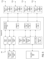
- FIG. 6 is a block diagram of a PHY layer 600 that shows one example of a split between the PHY layer modules described in FIG. 5 .
- This example includes a split between uplink and downlink processing and a split between secondary and primary processing.
- FIG. 6 depicts an example for a single carrier PHY with single-in-single-out ("SISO") (e.g., one antenna) for a particular assignment of the stages to PHY entities.
- the PHY entities can handle multiple carriers and serve multiple antennas in a multiple-in-multiple-out (“MIMO") configuration.
- MIMO multiple-in-multiple-out
- different processing stages can be assigned to the pPHY-U 602, pPHY-D 604, sPHY-U 606, and sPHY-D 608 entities.
- the splits S2P-U 610 and S2P-D 612 between the PHY entities can communicate different types of information depending on the assignment.
- MACPHY-D 614 can include information to be transmitted that is processed by pPHY-D 604 functions and the sPHY-D 608 functions, which can include a transmit chain ("TX-chain”) that can implement low power signal processes.
- the IQ data 616a representing carrier information can be received from the digital frontend transmit (“DFE-TX") block and IQ data 616b representing carrier information can be transmitted by the digital frontend receive (“DFE-RX”) block.
- DFE-TX digital frontend transmit
- DFE-RX digital frontend receive
- the distributed PHY layer functionality depicted in FIGs. 5 and 6 can be combined with the distributed SeNB functionality depicted in one or more of FIGs. 2-4 .
- one or more of the low-layer processing modules 214a-d, 300, or 400 depicted in FIGs. 2-4 can implement one or more of the pPHY-U, pPHY-D, sPHY-U, or sPHY-D functions depicted in FIGs. 5 and 6 in addition to the SeNB functionality described herein.
- FIG. 7 is a flow chart depicting an example of a process for distributing base station functionality in a telecommunication system (e.g., a DAS, repeater, or radio access network).
- a telecommunication system e.g., a DAS, repeater, or radio access network.
- data is transmitted between a unit and radio units of a telecommunication system.
- the unit may be a head-end unit, an aggregation unit, or another unit of the telecommunication system.
- One or more units of the telecommunication system may include a low-layer processing module.
- the low-layer processing module may be integrated into the unit.
- the low-layer processing module may be a plug-in card or other suitable device that can be installed in a component in the telecommunication system.
- physical layer processing is performed in at least one of the unit and a radio unit.
- physical layer processing may be split between uplink physical layer processing and downlink physical layer processing.
- the unit and the radio unit may each perform a portion of the processing.
- the radio unit may perform uplink physical layer processing and the unit may perform downlink physical layer processing.
- the uplink physical layer processing can be split between secondary uplink physical layer processing and primary uplink physical layer processing.
- the downlink physical layer processing can be split between secondary downlink physical layer processing and primary downlink physical layer processing.
- the radio unit may include a low-layer processing module that can perform primary uplink physical layer processing.
- a head-end unit or other suitable unit in communication with the radio unit may include a low-layer processing module that can perform secondary uplink physical layer processing.
- the radio unit may include a low-layer processing module that can perform primary uplink physical layer processing and secondary downlink physical layer processing.
- a head-end unit or other suitable unit in communication with the radio unit may include a low-layer processing module that can perform secondary uplink physical layer processing and primary downlink physical layer processing.
- radio transport layer processing is performed in at least one of the unit and a radio unit.
- the unit may communicate mobile communication signals with the radio unit.
- the unit may communicate mobile communication signals with a base-station entity, base-station component (such as a baseband unit or remote radio head), or core-network entity.
- the mobile communication signals may include digital RF data, baseband IQ data, X2 data, and S1 data.
- FIG. 7 depicts both of blocks 704, 706, other implementations are possible.
- a telecommunication system e.g., a DAS, a repeater
- a telecommunication system e.g., a DAS, a repeater
- this disclosure includes references to "a SeNB module” and "a MeNB.”
- any suitable implementation can be covered by the examples described herein, including implementations involving one or more SeNB modules, one or more cells serviced using one or more SeNB modules, one or more SeNBs being implemented using a given SeNB module, one or more LTE cells being implemented using one or more SeNB modules, one or more SeNB modules being used for one or more given providers being serviced, one or more MeNBs in communication with one or more SeNB modules, etc.
Landscapes
- Engineering & Computer Science (AREA)
- Computer Networks & Wireless Communication (AREA)
- Signal Processing (AREA)
- Mobile Radio Communication Systems (AREA)
Claims (15)
- Système de télécommunications (102, 202) qui est situé à distance d'une entité de station de base externe (104, 204, 502) ou d'un composant de station de base, le système de télécommunications (102, 202) comprenant :une interface (210, 214, 220) avec une circuiterie configurée pour communiquer avec l'entité de station de base externe (104, 204, 502) ou le composant de station de base ;une pluralité d'unités radio séparées spatialement (112, 212, 512) qui sont couplées de manière communicative à l'interface (210, 214, 220) via une unité d'agrégation (108, 208, 510), dans lequel les unités radio (112, 212, 512) peuvent être positionnées dans une zone pour fournir une couverture sans fil à des dispositifs terminaux ;l'unité d'agrégation (108, 208, 510) pouvant être couplée de manière communicative entre l'interface (210, 214, 220) et la pluralité d'unités radio, l'unité d'agrégation (108, 208, 510) étant physiquement séparée des unités radio (112, 212, 512) ; etun module de traitement de couche basse (116, 214, 300, 400, 516, 518, 526, 528, 530, 532) dans au moins l'une parmi l'unité d'agrégation ou une unité radio (112, 212, 512) de la pluralité d'unités radio (112, 212, 512), le module de traitement de couche basse (116, 214, 300, 400, 516, 518, 526, 528, 530, 532) étant configuré pour réaliser un traitement de couche physique qui est divisé entre un traitement de couche physique de liaison montante et un traitement de couche physique de liaison descendante,dans lequel la démodulation et le décodage de données sont réalisés en tant que partie du traitement de couche physique de liaison montante secondaire au niveau de l'unité d'agrégation (108, 208, 510),dans lequel les données décodées sont envoyées via une interface de contrôle d'accès au support/physique, MACPHY, de liaison montante vers un routeur de messages, le routeur de messages faisant partie de l'interface configurée pour communiquer avec l'entité de station de base externe ou le composant de station de base, etdans lequel un traitement de fréquence radio est réalisé en tant que partie d'un traitement de couche physique de liaison montante primaire au niveau de la pluralité d'unités radio (112, 212, 512).
- Système de télécommunications (102, 202) selon la revendication 1,
dans lequel le traitement de couche physique de liaison descendante est divisé entre un traitement de couche physique de liaison descendante secondaire et un traitement de couche physique de liaison descendante primaire. - Système de télécommunications (102, 202) selon la revendication 2, dans lequel l'unité radio (112, 212, 512) de la pluralité d'unités radio (112, 212, 512) comprend un premier module de traitement de couche basse (116, 214, 300, 400, 516, 518, 530, 532) configurée pour réaliser le traitement de couche physique de liaison montante primaire et le traitement de couche physique de liaison descendante, dans lequel l'unité d'agrégation (108, 208, 510) comprend un deuxième module de traitement de couche basse (116, 214, 300, 400, 526, 528) configurée pour réaliser le traitement de couche physique de liaison montante secondaire.
- Système de télécommunications selon la revendication 2, dans lequel une unité radio (112, 212, 512) de la pluralité d'unités radio (112, 212, 512) comprend un premier module de traitement de couche basse (116, 214, 300, 400, 516, 518, 530, 532) configurée pour le traitement de la couche physique de liaison montante primaire et le traitement de couche physique de liaison descendante secondaire, dans lequel l'unité d'agrégation (108, 208, 510) comprend un deuxième module de traitement de couche basse (116, 214, 300, 400, 526, 528) configurée pour le traitement de la couche physique de liaison montante secondaire et le traitement de la couche physique de liaison descendante primaire.
- Système de télécommunications (102, 202) selon la revendication 2, dans lequel une unité radio (112, 212, 512) de la pluralité d'unités radio (112, 212, 512) comprend un premier module de traitement de couche basse (116, 214, 300, 400, 516, 518, 530, 532) configurée pour le traitement de la couche physique de liaison montante et le traitement de couche physique de liaison descendante secondaire, dans lequel l'unité d'agrégation (108, 208, 510) comprend un deuxième module de traitement de couche basse (116, 214, 300, 400, 526, 528) configurée pour le traitement de la couche physique de liaison descendante primaire.
- Système de télécommunications (102, 202) selon l'une quelconque des revendications 1 à 5, dans lequel le module de traitement de couche basse (116, 214, 300, 400, 526, 528, 530, 532) est un dispositif secondaire eNodeB (« SeNB ») (302, 402) et est en outre configuré pour réaliser un traitement de couche de transport radio.
- Système de télécommunications (102, 202) selon la revendication 6, dans lequel le dispositif SeNB (302, 402) est en outre configuré pour réaliser au moins l'un parmi un traitement de couche de commande d'accès au support, un traitement de commande de liaison radio ou un traitement de protocole de convergence de données par paquets.
- Système de télécommunications selon l'une quelconque des revendications 1 à 7, dans lequel le système de télécommunications (102, 202) étend la couverture de l'entité de station de base (104, 204, 502) ou du composant de station de base.
- Système de télécommunications (102, 202) selon l'une quelconque des revendications 1 à 8, dans lequel le système de télécommunications (102, 202) est au moins l'un parmi un répéteur (500) couplé en communication à l'entité de station de base externe (104, 204, 502) ou à un composant de station de base pour former une station de base distribuée, un réseau d'accès radio ou un système d'antennes distribuées (102).
- Système de télécommunications (102, 202) selon l'une quelconque des revendications 1 à 9, dans lequel l'entité de station de base externe (104, 204, 502) ou le composant de station de base comprend au moins l'un parmi une unité de bande de base, une tête radio distante et un eNodeB maître (204, 304, 404).
- Procédé comprenant :la transmission de données entre une unité de tête de réseau (106, 206) et une pluralité d'unités radio spatialement séparées (112, 212, 512) qui sont couplées en communication à l'unité de tête de réseau via une unité d'agrégation dans un système de télécommunications (102, 202), l'unité d'agrégation (108, 208, 510) étant physiquement séparée des unités radio (112, 212, 512), dans lequel l'unité de tête de réseau (106, 206) est couplée à une entité de station de base (104, 204, 502) ou à un composant de station de base, dans lequel le système de télécommunications (102, 202) étend la couverture de l'entité de station de base (104, 204, 502) ou du composant de station de base ; etla réalisation d'un traitement de couche physique distribué dans au moins une unité de tête de réseau (106, 206) ou une unité radio (112, 212, 512) de la pluralité d'unités radio (112, 212, 512),dans lequel la démodulation et le décodage de données sont réalisés dans le cadre du traitement de couche physique de liaison montante secondaire,dans lequel les données décodées sont envoyées via une interface de contrôle d'accès au support/physique, MACPHY, de liaison montante à un routeur de messages, le routeur de messages faisant partie de l'interface configurée pour communiquer avec l'entité de station de base externe ou le composant de station de base, etdans lequel le traitement radiofréquence est réalisé en tant que partie du traitement de couche physique de liaison montante primaire au niveau de la pluralité d'unités radio (112, 212, 512).
- Procédé selon la revendication 11, comprenant en outre la réalisation de fonctions SeNB dans au moins l'une parmi l'unité de tête de réseau (106, 206) ou l'unité radio (112, 212, 512).
- Procédé selon la revendication 12, dans lequel les fonctions SeNB comprennent un traitement de couche de transport radio.
- Procédé selon l'une quelconque des revendications 11 à 13, dans lequel le traitement de couche physique distribué est réalisé en divisant le traitement de couche physique distribué entre un traitement de couche physique de liaison montante et un traitement de couche physique de liaison descendante, et dans lequel l'unité de tête de réseau (106, 206) et l'unité radio (112, 212, 512) réalisent chacune une portion du traitement.
- Procédé selon l'une quelconque des revendications 11 à 14, dans lequel le système de télécommunications (102, 202) est au moins l'un parmi un répéteur (500), un réseau d'accès radio et un système d'antennes distribuées (102, 202), dans lequel l'entité de station de base externe (104, 204, 502) ou le composant de station de base comprend au moins l'un parmi une unité de bande de base, une tête radio distante et d'un eNodeB maître (204, 304, 404).
Applications Claiming Priority (3)
| Application Number | Priority Date | Filing Date | Title |
|---|---|---|---|
| US201562180131P | 2015-06-16 | 2015-06-16 | |
| US201562193338P | 2015-07-16 | 2015-07-16 | |
| PCT/EP2016/063811 WO2016202893A1 (fr) | 2015-06-16 | 2016-06-15 | Systèmes de télécommunications dotés de fonctionnalité de station de base distribuée |
Publications (2)
| Publication Number | Publication Date |
|---|---|
| EP3311507A1 EP3311507A1 (fr) | 2018-04-25 |
| EP3311507B1 true EP3311507B1 (fr) | 2025-04-09 |
Family
ID=57546633
Family Applications (1)
| Application Number | Title | Priority Date | Filing Date |
|---|---|---|---|
| EP16729897.5A Active EP3311507B1 (fr) | 2015-06-16 | 2016-06-15 | Systèmes de télécommunications dotés de fonctionnalité de station de base distribuée |
Country Status (4)
| Country | Link |
|---|---|
| US (1) | US10341880B2 (fr) |
| EP (1) | EP3311507B1 (fr) |
| CN (1) | CN107925471B (fr) |
| WO (1) | WO2016202893A1 (fr) |
Families Citing this family (41)
| Publication number | Priority date | Publication date | Assignee | Title |
|---|---|---|---|---|
| WO2016085964A1 (fr) | 2014-11-25 | 2016-06-02 | View, Inc. | Antennes de fenêtre |
| US20210063836A1 (en) | 2017-04-26 | 2021-03-04 | View, Inc. | Building network |
| US10989977B2 (en) | 2011-03-16 | 2021-04-27 | View, Inc. | Onboard controller for multistate windows |
| US9780928B2 (en) | 2011-10-17 | 2017-10-03 | Golba Llc | Method and system for providing diversity in a network that utilizes distributed transceivers and array processing |
| US9253587B2 (en) | 2012-08-08 | 2016-02-02 | Golba Llc | Method and system for intelligently controlling propagation environments in distributed transceiver communications |
| US11868103B2 (en) | 2014-03-05 | 2024-01-09 | View, Inc. | Site monitoring system |
| KR102336168B1 (ko) | 2014-03-05 | 2021-12-07 | 뷰, 인크. | 스위칭가능한 광 디바이스들 및 제어기들을 포함하는 사이트들 모니터링 |
| US11114742B2 (en) | 2014-11-25 | 2021-09-07 | View, Inc. | Window antennas |
| US12235560B2 (en) | 2014-11-25 | 2025-02-25 | View, Inc. | Faster switching electrochromic devices |
| US11740948B2 (en) | 2014-12-08 | 2023-08-29 | View, Inc. | Multiple interacting systems at a site |
| EP3269118B8 (fr) | 2015-03-11 | 2021-03-17 | CommScope, Inc. of North Carolina | Réseau d'accès radio distribué comprenant une liaison de raccordement aux sites cellulaires adaptative |
| CN107925471B (zh) | 2015-06-16 | 2020-05-22 | 安德鲁无线系统有限公司 | 具有分布式基站功能的电信系统 |
| US12366111B2 (en) | 2015-09-18 | 2025-07-22 | View Operating Corporation | Trunk line window controllers |
| US10608734B2 (en) * | 2015-10-22 | 2020-03-31 | Phluido, Inc. | Virtualization and orchestration of a radio access network |
| US10517021B2 (en) | 2016-06-30 | 2019-12-24 | Evolve Cellular Inc. | Long term evolution-primary WiFi (LTE-PW) |
| WO2018017468A1 (fr) | 2016-07-18 | 2018-01-25 | Phluido, Inc. | Synchronisation d'unités radio dans des réseaux d'accès radio |
| US10854995B2 (en) | 2016-09-02 | 2020-12-01 | Movandi Corporation | Wireless transceiver having receive antennas and transmit antennas with orthogonal polarizations in a phased array antenna panel |
| KR101822863B1 (ko) * | 2016-09-09 | 2018-01-29 | 주식회사 쏠리드 | 셀룰라 통신 시스템 |
| US10199717B2 (en) | 2016-11-18 | 2019-02-05 | Movandi Corporation | Phased array antenna panel having reduced passive loss of received signals |
| US12147142B2 (en) | 2017-04-26 | 2024-11-19 | View, Inc. | Remote management of a facility |
| US12603091B2 (en) | 2017-04-26 | 2026-04-14 | View Operating Corporation | Immersive collaboration of remote participants via media displays |
| US10321332B2 (en) | 2017-05-30 | 2019-06-11 | Movandi Corporation | Non-line-of-sight (NLOS) coverage for millimeter wave communication |
| US10916861B2 (en) | 2017-05-30 | 2021-02-09 | Movandi Corporation | Three-dimensional antenna array module |
| US10484078B2 (en) | 2017-07-11 | 2019-11-19 | Movandi Corporation | Reconfigurable and modular active repeater device |
| US12368497B2 (en) | 2017-07-11 | 2025-07-22 | Movandi Corporation | Repeater device for 5G new radio communication |
| US10348371B2 (en) | 2017-12-07 | 2019-07-09 | Movandi Corporation | Optimized multi-beam antenna array network with an extended radio frequency range |
| US10862559B2 (en) | 2017-12-08 | 2020-12-08 | Movandi Corporation | Signal cancellation in radio frequency (RF) device network |
| US10090887B1 (en) | 2017-12-08 | 2018-10-02 | Movandi Corporation | Controlled power transmission in radio frequency (RF) device network |
| US10171115B1 (en) | 2017-12-19 | 2019-01-01 | Movandi Corporation | Outphasing calibration in a radio frequency (RF) transmitter device |
| US12016084B2 (en) | 2018-01-04 | 2024-06-18 | Commscope Technologies Llc | Management of a split physical layer in a radio area network |
| US10637159B2 (en) | 2018-02-26 | 2020-04-28 | Movandi Corporation | Waveguide antenna element-based beam forming phased array antenna system for millimeter wave communication |
| US11088457B2 (en) | 2018-02-26 | 2021-08-10 | Silicon Valley Bank | Waveguide antenna element based beam forming phased array antenna system for millimeter wave communication |
| US10797734B2 (en) * | 2018-08-01 | 2020-10-06 | Commscope Technologies Llc | System with multiple virtual radio units in a radio unit that is remote from at least one baseband controller |
| US11205855B2 (en) | 2018-12-26 | 2021-12-21 | Silicon Valley Bank | Lens-enhanced communication device |
| US11145986B2 (en) | 2018-12-26 | 2021-10-12 | Silicon Valley Bank | Lens-enhanced communication device |
| JP7644501B2 (ja) | 2019-05-09 | 2025-03-12 | ビュー オペレーティング コーポレーション | 建物内の制御されたカバレッジのためのアンテナシステム |
| EP3977557A1 (fr) | 2019-05-31 | 2022-04-06 | View, Inc. | Antenne de bâtiment |
| WO2022221651A1 (fr) * | 2021-04-15 | 2022-10-20 | View, Inc. | Routage dynamique de signaux dans une installation |
| TW202206925A (zh) | 2020-03-26 | 2022-02-16 | 美商視野公司 | 多用戶端網路中之存取及傳訊 |
| US12155786B2 (en) | 2021-12-16 | 2024-11-26 | T-Mobile Usa, Inc. | Image-based detection of modem crashes in mobile telephonic devices |
| US20250056223A1 (en) * | 2023-08-12 | 2025-02-13 | PHYTunes, Inc. | Personalized wi-fi systems and methods |
Citations (2)
| Publication number | Priority date | Publication date | Assignee | Title |
|---|---|---|---|---|
| WO2014070236A1 (fr) * | 2012-10-31 | 2014-05-08 | Andrew Llc | Transport numérique en bande de base dans des systèmes de distribution de télécommunications |
| WO2014085115A1 (fr) * | 2012-11-29 | 2014-06-05 | Corning Cable Systems Llc | Liaison d'antennes d'unité distante intra-cellule/inter-cellule hybride dans des systèmes d'antenne distribués (das) à entrées multiples sorties multiples (mimo) |
Family Cites Families (7)
| Publication number | Priority date | Publication date | Assignee | Title |
|---|---|---|---|---|
| CN101018101A (zh) * | 2006-02-10 | 2007-08-15 | 华为技术有限公司 | 数据传输方法和系统及数据发送和接收装置 |
| CN101990237B (zh) * | 2009-07-29 | 2015-05-13 | 中兴通讯股份有限公司 | 一种中继链路数据传输方法及系统 |
| EP2719093B1 (fr) | 2011-06-13 | 2020-01-15 | LGC Wireless, LLC | Architectures de système d'antenne distribué |
| KR101971584B1 (ko) | 2011-06-29 | 2019-04-23 | 콤스코프 커넥티비티 엘엘씨 | 진화된 분산 안테나 시스템 |
| EP2592863B1 (fr) * | 2011-11-14 | 2014-01-08 | Alcatel Lucent | Équilibrage de charge distribuée dans un réseau d'accès radio |
| JP6301082B2 (ja) * | 2013-07-30 | 2018-03-28 | 株式会社Kddi総合研究所 | 通信装置並びにその制御方法、基地局装置並びにその制御方法、及びプログラム |
| CN107925471B (zh) | 2015-06-16 | 2020-05-22 | 安德鲁无线系统有限公司 | 具有分布式基站功能的电信系统 |
-
2016
- 2016-06-15 CN CN201680047917.4A patent/CN107925471B/zh not_active Expired - Fee Related
- 2016-06-15 EP EP16729897.5A patent/EP3311507B1/fr active Active
- 2016-06-15 US US15/737,241 patent/US10341880B2/en active Active
- 2016-06-15 WO PCT/EP2016/063811 patent/WO2016202893A1/fr not_active Ceased
Patent Citations (2)
| Publication number | Priority date | Publication date | Assignee | Title |
|---|---|---|---|---|
| WO2014070236A1 (fr) * | 2012-10-31 | 2014-05-08 | Andrew Llc | Transport numérique en bande de base dans des systèmes de distribution de télécommunications |
| WO2014085115A1 (fr) * | 2012-11-29 | 2014-06-05 | Corning Cable Systems Llc | Liaison d'antennes d'unité distante intra-cellule/inter-cellule hybride dans des systèmes d'antenne distribués (das) à entrées multiples sorties multiples (mimo) |
Also Published As
| Publication number | Publication date |
|---|---|
| CN107925471B (zh) | 2020-05-22 |
| WO2016202893A1 (fr) | 2016-12-22 |
| US10341880B2 (en) | 2019-07-02 |
| US20180176799A1 (en) | 2018-06-21 |
| EP3311507A1 (fr) | 2018-04-25 |
| CN107925471A (zh) | 2018-04-17 |
Similar Documents
| Publication | Publication Date | Title |
|---|---|---|
| US10341880B2 (en) | Telecommunication systems with distributed base station functionality | |
| Teyeb et al. | Integrated access backhauled networks | |
| RU2723082C1 (ru) | Система радиостанции, радиотерминал и способы в них | |
| US10595260B2 (en) | Concept for load balancing in a radio access network | |
| US10206219B2 (en) | Base station apparatus and resource management method and data processing method in wireless communication system | |
| US9049699B2 (en) | Wireless backhaul | |
| KR101472100B1 (ko) | 무선통신 시스템에서 기지국 장비 및 데이터 처리 방법 | |
| US20130315134A1 (en) | Intra IP Communication within a Relay Node for a Radio Telecommunication Network | |
| EP3183863B1 (fr) | Système d'antennes distribuées à allocation adaptative entre données en rf numérisées et données formatées en ip | |
| CN102037758A (zh) | 包括与公用网络元件耦合的私有基站的网络 | |
| US20100103869A1 (en) | Transferring data in a mobile telephony network | |
| KR101954226B1 (ko) | 기지국 장비, 자원 관리 방법 및 데이터 처리 방법 | |
| CN108243432A (zh) | 一种无线接入与回传一体化小基站原型设计方法 | |
| EP2789206B1 (fr) | Support de liaison terrestre à microondes intégrée dans des produits cellulaires | |
| KR102110142B1 (ko) | 무선통신장치 및 데이터 스트림 전달 방법, 데이터스트림 변환장치 | |
| KR101822863B1 (ko) | 셀룰라 통신 시스템 | |
| CN101420260B (zh) | 无线电设备节点、分布式无线通信基站及其通信方法 | |
| US8406777B2 (en) | Systems and methods of dynamic segregation of managed wireless resources by traffic type | |
| Chochliouros et al. | A multi-hop relay station software architecture design, on the basis of the wimax ieee 802.16 j standard | |
| EP2844027A1 (fr) | Relier une dispositif de radiocommunication à une station de base | |
| Voudouris et al. | Developing an Innovative Multi-hop Relay Station Software Architecture in the Scope of the REWIND European Research Programme |
Legal Events
| Date | Code | Title | Description |
|---|---|---|---|
| STAA | Information on the status of an ep patent application or granted ep patent |
Free format text: STATUS: THE INTERNATIONAL PUBLICATION HAS BEEN MADE |
|
| PUAI | Public reference made under article 153(3) epc to a published international application that has entered the european phase |
Free format text: ORIGINAL CODE: 0009012 |
|
| STAA | Information on the status of an ep patent application or granted ep patent |
Free format text: STATUS: REQUEST FOR EXAMINATION WAS MADE |
|
| 17P | Request for examination filed |
Effective date: 20180109 |
|
| AK | Designated contracting states |
Kind code of ref document: A1 Designated state(s): AL AT BE BG CH CY CZ DE DK EE ES FI FR GB GR HR HU IE IS IT LI LT LU LV MC MK MT NL NO PL PT RO RS SE SI SK SM TR |
|
| AX | Request for extension of the european patent |
Extension state: BA ME |
|
| RIN1 | Information on inventor provided before grant (corrected) |
Inventor name: KUMMETZ, THOMAS Inventor name: LANGE, KELD KNUT |
|
| DAV | Request for validation of the european patent (deleted) | ||
| DAX | Request for extension of the european patent (deleted) | ||
| STAA | Information on the status of an ep patent application or granted ep patent |
Free format text: STATUS: EXAMINATION IS IN PROGRESS |
|
| 17Q | First examination report despatched |
Effective date: 20210317 |
|
| GRAP | Despatch of communication of intention to grant a patent |
Free format text: ORIGINAL CODE: EPIDOSNIGR1 |
|
| STAA | Information on the status of an ep patent application or granted ep patent |
Free format text: STATUS: GRANT OF PATENT IS INTENDED |
|
| INTG | Intention to grant announced |
Effective date: 20241219 |
|
| GRAS | Grant fee paid |
Free format text: ORIGINAL CODE: EPIDOSNIGR3 |
|
| RAP1 | Party data changed (applicant data changed or rights of an application transferred) |
Owner name: COMMSCOPE HOLDINGS (GERMANY) GMBH & CO. KG |
|
| GRAA | (expected) grant |
Free format text: ORIGINAL CODE: 0009210 |
|
| STAA | Information on the status of an ep patent application or granted ep patent |
Free format text: STATUS: THE PATENT HAS BEEN GRANTED |
|
| AK | Designated contracting states |
Kind code of ref document: B1 Designated state(s): AL AT BE BG CH CY CZ DE DK EE ES FI FR GB GR HR HU IE IS IT LI LT LU LV MC MK MT NL NO PL PT RO RS SE SI SK SM TR |
|
| REG | Reference to a national code |
Ref country code: GB Ref legal event code: FG4D |
|
| REG | Reference to a national code |
Ref country code: CH Ref legal event code: EP |
|
| REG | Reference to a national code |
Ref country code: DE Ref legal event code: R096 Ref document number: 602016091829 Country of ref document: DE |
|
| REG | Reference to a national code |
Ref country code: IE Ref legal event code: FG4D |
|
| REG | Reference to a national code |
Ref country code: NL Ref legal event code: MP Effective date: 20250409 |
|
| RAP2 | Party data changed (patent owner data changed or rights of a patent transferred) |
Owner name: ANDREW WIRELESS SYSTEMS GMBH |
|
| PG25 | Lapsed in a contracting state [announced via postgrant information from national office to epo] |
Ref country code: NL Free format text: LAPSE BECAUSE OF FAILURE TO SUBMIT A TRANSLATION OF THE DESCRIPTION OR TO PAY THE FEE WITHIN THE PRESCRIBED TIME-LIMIT Effective date: 20250409 |
|
| REG | Reference to a national code |
Ref country code: AT Ref legal event code: MK05 Ref document number: 1784501 Country of ref document: AT Kind code of ref document: T Effective date: 20250409 |
|
| PG25 | Lapsed in a contracting state [announced via postgrant information from national office to epo] |
Ref country code: ES Free format text: LAPSE BECAUSE OF FAILURE TO SUBMIT A TRANSLATION OF THE DESCRIPTION OR TO PAY THE FEE WITHIN THE PRESCRIBED TIME-LIMIT Effective date: 20250409 Ref country code: PT Free format text: LAPSE BECAUSE OF FAILURE TO SUBMIT A TRANSLATION OF THE DESCRIPTION OR TO PAY THE FEE WITHIN THE PRESCRIBED TIME-LIMIT Effective date: 20250811 Ref country code: FI Free format text: LAPSE BECAUSE OF FAILURE TO SUBMIT A TRANSLATION OF THE DESCRIPTION OR TO PAY THE FEE WITHIN THE PRESCRIBED TIME-LIMIT Effective date: 20250409 |
|
| REG | Reference to a national code |
Ref country code: LT Ref legal event code: MG9D |
|
| PG25 | Lapsed in a contracting state [announced via postgrant information from national office to epo] |
Ref country code: NO Free format text: LAPSE BECAUSE OF FAILURE TO SUBMIT A TRANSLATION OF THE DESCRIPTION OR TO PAY THE FEE WITHIN THE PRESCRIBED TIME-LIMIT Effective date: 20250709 Ref country code: GR Free format text: LAPSE BECAUSE OF FAILURE TO SUBMIT A TRANSLATION OF THE DESCRIPTION OR TO PAY THE FEE WITHIN THE PRESCRIBED TIME-LIMIT Effective date: 20250710 |
|
| PG25 | Lapsed in a contracting state [announced via postgrant information from national office to epo] |
Ref country code: PL Free format text: LAPSE BECAUSE OF FAILURE TO SUBMIT A TRANSLATION OF THE DESCRIPTION OR TO PAY THE FEE WITHIN THE PRESCRIBED TIME-LIMIT Effective date: 20250409 |
|
| PG25 | Lapsed in a contracting state [announced via postgrant information from national office to epo] |
Ref country code: BG Free format text: LAPSE BECAUSE OF FAILURE TO SUBMIT A TRANSLATION OF THE DESCRIPTION OR TO PAY THE FEE WITHIN THE PRESCRIBED TIME-LIMIT Effective date: 20250409 |
|
| PG25 | Lapsed in a contracting state [announced via postgrant information from national office to epo] |
Ref country code: HR Free format text: LAPSE BECAUSE OF FAILURE TO SUBMIT A TRANSLATION OF THE DESCRIPTION OR TO PAY THE FEE WITHIN THE PRESCRIBED TIME-LIMIT Effective date: 20250409 |
|
| PG25 | Lapsed in a contracting state [announced via postgrant information from national office to epo] |
Ref country code: AT Free format text: LAPSE BECAUSE OF FAILURE TO SUBMIT A TRANSLATION OF THE DESCRIPTION OR TO PAY THE FEE WITHIN THE PRESCRIBED TIME-LIMIT Effective date: 20250409 |
|
| PG25 | Lapsed in a contracting state [announced via postgrant information from national office to epo] |
Ref country code: RS Free format text: LAPSE BECAUSE OF FAILURE TO SUBMIT A TRANSLATION OF THE DESCRIPTION OR TO PAY THE FEE WITHIN THE PRESCRIBED TIME-LIMIT Effective date: 20250709 |
|
| PG25 | Lapsed in a contracting state [announced via postgrant information from national office to epo] |
Ref country code: IS Free format text: LAPSE BECAUSE OF FAILURE TO SUBMIT A TRANSLATION OF THE DESCRIPTION OR TO PAY THE FEE WITHIN THE PRESCRIBED TIME-LIMIT Effective date: 20250809 |
|
| PG25 | Lapsed in a contracting state [announced via postgrant information from national office to epo] |
Ref country code: LV Free format text: LAPSE BECAUSE OF FAILURE TO SUBMIT A TRANSLATION OF THE DESCRIPTION OR TO PAY THE FEE WITHIN THE PRESCRIBED TIME-LIMIT Effective date: 20250409 |
|
| PGFP | Annual fee paid to national office [announced via postgrant information from national office to epo] |
Ref country code: DE Payment date: 20251126 Year of fee payment: 10 |
|
| REG | Reference to a national code |
Ref country code: DE Ref legal event code: R097 Ref document number: 602016091829 Country of ref document: DE |
|
| PG25 | Lapsed in a contracting state [announced via postgrant information from national office to epo] |
Ref country code: SM Free format text: LAPSE BECAUSE OF FAILURE TO SUBMIT A TRANSLATION OF THE DESCRIPTION OR TO PAY THE FEE WITHIN THE PRESCRIBED TIME-LIMIT Effective date: 20250409 Ref country code: DK Free format text: LAPSE BECAUSE OF FAILURE TO SUBMIT A TRANSLATION OF THE DESCRIPTION OR TO PAY THE FEE WITHIN THE PRESCRIBED TIME-LIMIT Effective date: 20250409 |
|
| PG25 | Lapsed in a contracting state [announced via postgrant information from national office to epo] |
Ref country code: CZ Free format text: LAPSE BECAUSE OF FAILURE TO SUBMIT A TRANSLATION OF THE DESCRIPTION OR TO PAY THE FEE WITHIN THE PRESCRIBED TIME-LIMIT Effective date: 20250409 |
|
| PG25 | Lapsed in a contracting state [announced via postgrant information from national office to epo] |
Ref country code: EE Free format text: LAPSE BECAUSE OF FAILURE TO SUBMIT A TRANSLATION OF THE DESCRIPTION OR TO PAY THE FEE WITHIN THE PRESCRIBED TIME-LIMIT Effective date: 20250409 |
|
| PG25 | Lapsed in a contracting state [announced via postgrant information from national office to epo] |
Ref country code: RO Free format text: LAPSE BECAUSE OF FAILURE TO SUBMIT A TRANSLATION OF THE DESCRIPTION OR TO PAY THE FEE WITHIN THE PRESCRIBED TIME-LIMIT Effective date: 20250409 Ref country code: SK Free format text: LAPSE BECAUSE OF FAILURE TO SUBMIT A TRANSLATION OF THE DESCRIPTION OR TO PAY THE FEE WITHIN THE PRESCRIBED TIME-LIMIT Effective date: 20250409 |
|
| REG | Reference to a national code |
Ref country code: CH Ref legal event code: H13 Free format text: ST27 STATUS EVENT CODE: U-0-0-H10-H13 (AS PROVIDED BY THE NATIONAL OFFICE) Effective date: 20260127 |
|
| PG25 | Lapsed in a contracting state [announced via postgrant information from national office to epo] |
Ref country code: IT Free format text: LAPSE BECAUSE OF FAILURE TO SUBMIT A TRANSLATION OF THE DESCRIPTION OR TO PAY THE FEE WITHIN THE PRESCRIBED TIME-LIMIT Effective date: 20250409 |
|
| PG25 | Lapsed in a contracting state [announced via postgrant information from national office to epo] |
Ref country code: MC Free format text: LAPSE BECAUSE OF FAILURE TO SUBMIT A TRANSLATION OF THE DESCRIPTION OR TO PAY THE FEE WITHIN THE PRESCRIBED TIME-LIMIT Effective date: 20250409 |
|
| PLBE | No opposition filed within time limit |
Free format text: ORIGINAL CODE: 0009261 |
|
| STAA | Information on the status of an ep patent application or granted ep patent |
Free format text: STATUS: NO OPPOSITION FILED WITHIN TIME LIMIT |
|
| PG25 | Lapsed in a contracting state [announced via postgrant information from national office to epo] |
Ref country code: LU Free format text: LAPSE BECAUSE OF NON-PAYMENT OF DUE FEES Effective date: 20250615 |
|
| REG | Reference to a national code |
Ref country code: CH Ref legal event code: L10 Free format text: ST27 STATUS EVENT CODE: U-0-0-L10-L00 (AS PROVIDED BY THE NATIONAL OFFICE) Effective date: 20260218 |
|
| REG | Reference to a national code |
Ref country code: BE Ref legal event code: MM Effective date: 20250630 |
|
| 26N | No opposition filed |
Effective date: 20260112 |
|
| GBPC | Gb: european patent ceased through non-payment of renewal fee |
Effective date: 20250709 |
|
| PG25 | Lapsed in a contracting state [announced via postgrant information from national office to epo] |
Ref country code: GB Free format text: LAPSE BECAUSE OF NON-PAYMENT OF DUE FEES Effective date: 20250709 |
|
| PG25 | Lapsed in a contracting state [announced via postgrant information from national office to epo] |
Ref country code: IE Free format text: LAPSE BECAUSE OF NON-PAYMENT OF DUE FEES Effective date: 20250615 |
|
| PG25 | Lapsed in a contracting state [announced via postgrant information from national office to epo] |
Ref country code: BE Free format text: LAPSE BECAUSE OF NON-PAYMENT OF DUE FEES Effective date: 20250630 |
|
| PG25 | Lapsed in a contracting state [announced via postgrant information from national office to epo] |
Ref country code: FR Free format text: LAPSE BECAUSE OF NON-PAYMENT OF DUE FEES Effective date: 20250630 |
|
| PG25 | Lapsed in a contracting state [announced via postgrant information from national office to epo] |
Ref country code: CH Free format text: LAPSE BECAUSE OF NON-PAYMENT OF DUE FEES Effective date: 20250630 |