EP3311703A1 - Dispositif de réglage permettant d'actionner un frein et unité mobile, en particulier chaise - Google Patents
Dispositif de réglage permettant d'actionner un frein et unité mobile, en particulier chaise Download PDFInfo
- Publication number
- EP3311703A1 EP3311703A1 EP17197815.8A EP17197815A EP3311703A1 EP 3311703 A1 EP3311703 A1 EP 3311703A1 EP 17197815 A EP17197815 A EP 17197815A EP 3311703 A1 EP3311703 A1 EP 3311703A1
- Authority
- EP
- European Patent Office
- Prior art keywords
- brake
- actuator
- load
- brake body
- adjusting
- Prior art date
- Legal status (The legal status is an assumption and is not a legal conclusion. Google has not performed a legal analysis and makes no representation as to the accuracy of the status listed.)
- Withdrawn
Links
- 230000007246 mechanism Effects 0.000 claims abstract description 62
- 230000033001 locomotion Effects 0.000 claims abstract description 52
- 230000009471 action Effects 0.000 claims description 6
- 238000006073 displacement reaction Methods 0.000 claims description 3
- 230000000694 effects Effects 0.000 claims description 3
- 210000000078 claw Anatomy 0.000 description 11
- 238000005096 rolling process Methods 0.000 description 11
- 230000005540 biological transmission Effects 0.000 description 9
- 239000000758 substrate Substances 0.000 description 8
- 210000001217 buttock Anatomy 0.000 description 2
- 230000008878 coupling Effects 0.000 description 2
- 238000010168 coupling process Methods 0.000 description 2
- 238000005859 coupling reaction Methods 0.000 description 2
- 235000004443 Ricinus communis Nutrition 0.000 description 1
- 240000000528 Ricinus communis Species 0.000 description 1
- 230000000903 blocking effect Effects 0.000 description 1
- 238000006243 chemical reaction Methods 0.000 description 1
- 230000006835 compression Effects 0.000 description 1
- 238000007906 compression Methods 0.000 description 1
- 238000013270 controlled release Methods 0.000 description 1
- 239000007787 solid Substances 0.000 description 1
Images





Classifications
-
- A—HUMAN NECESSITIES
- A47—FURNITURE; DOMESTIC ARTICLES OR APPLIANCES; COFFEE MILLS; SPICE MILLS; SUCTION CLEANERS IN GENERAL
- A47C—CHAIRS; SOFAS; BEDS
- A47C7/00—Parts, details, or accessories of chairs or stools
- A47C7/002—Chair or stool bases
- A47C7/004—Chair or stool bases for chairs or stools with central column, e.g. office chairs
-
- A—HUMAN NECESSITIES
- A47—FURNITURE; DOMESTIC ARTICLES OR APPLIANCES; COFFEE MILLS; SPICE MILLS; SUCTION CLEANERS IN GENERAL
- A47C—CHAIRS; SOFAS; BEDS
- A47C3/00—Chairs characterised by structural features; Chairs or stools with rotatable or vertically-adjustable seats
- A47C3/18—Chairs or stools with rotatable seat
-
- A—HUMAN NECESSITIES
- A47—FURNITURE; DOMESTIC ARTICLES OR APPLIANCES; COFFEE MILLS; SPICE MILLS; SUCTION CLEANERS IN GENERAL
- A47C—CHAIRS; SOFAS; BEDS
- A47C3/00—Chairs characterised by structural features; Chairs or stools with rotatable or vertically-adjustable seats
- A47C3/20—Chairs or stools with vertically-adjustable seats
- A47C3/30—Chairs or stools with vertically-adjustable seats with vertically-acting fluid cylinder
-
- A—HUMAN NECESSITIES
- A47—FURNITURE; DOMESTIC ARTICLES OR APPLIANCES; COFFEE MILLS; SPICE MILLS; SUCTION CLEANERS IN GENERAL
- A47C—CHAIRS; SOFAS; BEDS
- A47C7/00—Parts, details, or accessories of chairs or stools
- A47C7/002—Chair or stool bases
- A47C7/006—Chair or stool bases with castors
Definitions
- the present invention relates to an adjusting device comprising a brake body which is adjustable between a braking position in which the brake body is brought into frictional contact with a braking surface, and a release position in which the brake body is retracted from the braking surface, a load input section therefor is to receive a loading force of a user, and a load triggering mechanism, which converts a force acting on the load input portion loading force in an adjustment movement of the brake body from the release position to the braking position.
- the invention relates to a mobile unit with such an actuator, with which the movement of the mobile unit along a substrate can be braked.
- Actuators of the above type are known in the art, for example in the form of foot-operated brakes on rollable trolleys or other pieces of furniture.
- a brake By loading a load input section through the foot of a user, a brake can be adjusted from the release position to the braking position to prevent unintentional rolling away of the unit.
- a disadvantage of such braking devices is that the user has to perform a separate, sometimes somewhat complicated operation of the brake in order to ensure the securing of the unit against unintentional movement. If the user forgets the operation of the brake, then unintentional results or even accidents can not be ruled out, for example if a user leans on a piece of furniture that is not sufficiently secured against rolling away or sits down on it.
- the rolling or sliding movement of the mobile unit is generally desirable in some situations. So should be about in the case of an office chair provided with castors, mobility of the chair along the ground, even in the loaded state of the unit, may be possible in a controlled manner. Accordingly, there should basically be the possibility of an unrestricted movement of such a unit.
- an object of the present invention to provide an actuating device which can slow down or block inadvertent movement of the unit in a mobile unit, which, however, at the same time allows a controlled movement of the mobile unit at the request of the user.
- an adjusting device comprising a brake body which is adjustable between a braking position in which the brake body is brought into frictional contact with a braking surface, and a release position in which the brake body is retracted from the braking surface, a load input portion which is arranged to receive a loading force of a user, a load triggering mechanism which converts a loading force acting on the load input portion into an adjusting movement of the brake body from the release position to the braking position, and a brake release mechanism arranged to move the brake body from the braking position to the release position to adjust while acting on the load input section, the loading force.
- the adjusting device thus comprises, on the one hand, a load-triggering mechanism which ensures that the brake, upon application of a load by the user, reaches the braking position in order to prevent inadvertent movement in this way.
- a brake release mechanism according to the invention is provided which, even with continuous action of the loading force, a controlled release of the brake by user operation and thus a movement of mobile unit on request allows.
- the actuator is incorporated in a rollable piece of furniture such as an office chair
- a user's force acting in a vertical direction can be translated to a braking position of the brake body, so that the brake automatically becomes effective as soon as the user moves the piece of furniture downwardly loaded, for example, sits down on the chair or in a direction obliquely down against this leaning.
- the brake is automatically activated accordingly and prevents unintentional rolling away of the furniture under the effect of this loading force. If the user then sits on the furniture or leaning against it and then decides to allow a rolling movement of the furniture, the brake release mechanism of the invention allows the brake body to be adjusted to the release position so that the desired movement can be made along the ground.
- the adjusting device further comprises a return mechanism, which resets the load release mechanism in an initial state upon removal of the loading force, so that the load release mechanism then converts a load force acting again on the load input portion into an adjustment movement of the brake body from the release position to the brake position.
- a return mechanism which resets the load release mechanism in an initial state upon removal of the loading force, so that the load release mechanism then converts a load force acting again on the load input portion into an adjustment movement of the brake body from the release position to the brake position.
- the return mechanism reliably and automatically returns the actuator to an initial state, so that when re-acting the load, such as the user or a another user sets again on the piece of furniture or leans against this, the load release mechanism always automatically puts the brake body in the braking position to secure the mobile unit against accidental rolling or slipping.
- the load receiving portion and the load triggering mechanism are adapted to receive a substantially vertically downwardly acting loading force.
- the braking function can then be activated in particular at least partially by the weight of a user.
- the brake body can move in its movement from the release position to the braking position in the downward direction to allow a simple structure and reliable operation.
- a downward force acting force can be converted by the weight of the user in a simple manner in a braking force.
- the load triggering mechanism comprises a first actuating element, which is movable by the action of the loading force along a control axis, for example, vertically downward movable.
- the loading force can be used directly as a force to move the actuator.
- the first adjusting element may be biased by a first elastic means in a direction counteracting the loading force, so that a removal of the loading force can be automatically converted into a corresponding opposite movement of the actuating element and a corresponding provision of the adjusting device is possible.
- the actuator transmits the loading force to a brake actuator to cause the actual braking movement of the brake body.
- the brake body may be formed on the brake actuator (or even form the brake actuator itself) or the brake body can be moved by the brake actuator.
- the brake release mechanism may in particular be adapted to adjust the brake control element in its movement from the braking position to the release position so that a distance between the brake body and the first control element is smaller.
- the brake release mechanism allows an adjustment of the brake body from the braking position to the release position, and this although the first actuator remains in the loaded position. In other words, the brake body moves in the power transmission chain to the first actuator.
- a second elastic means may be provided which biases the brake body in a direction towards the first actuating element. This can be helpful in particular when the brake body is located in the vertical direction below the first control element, so that the second elastic device can then be selected so that it overcomes the weight of the brake body or the brake actuator.
- the brake release mechanism can cause relative rotation between the brake actuator and the first actuator, in particular a relative rotation about the actuator.
- Such a brake release mechanism can in particular be designed to save space.
- the brake releasing mechanism may further comprise, in another embodiment of the invention, an operating portion for manual operation by a user, a second adjusting member movable by the operating portion along the adjusting axis, and a control portion converting the sliding movement of the second adjusting member into rotational movement of the first adjusting member.
- This embodiment is particularly advantageous when said rotational movement of the first actuator changes a coupling between the first actuator and the brake actuator, for example, changed between a state for transmitting a motive force from the first actuator to the brake actuator in the direction of the braking position and a state of cancellation this power transmission, so that an approximation of the brake actuator to the first actuator is possible.
- the adjusting device further comprises a foot portion, relative to which the load input portion is rotatably mounted, and that the brake release mechanism comprises an operating portion for manual operation by a user, wherein the actuating portion is rotatable relative to the foot portion together with the load input portion.
- the operating section rotates / raises in unison with the seating surface and the load input section and is always in the same position with respect to a person seated thereon, so that it can be operated reliably.
- the operating portion may be a lever whose fulcrum may then be rotatable relative to the foot portion together with the load input portion.
- the lever rotation axis can thereby run parallel to the axis of rotation of the load input section relative to the foot section.
- the operating portion may comprise a cable pull mechanism with a pull cable guided in a cable guide, in which case the cable guide together with the load input portion may be rotatable relative to the foot portion.
- a cable pull mechanism allows increased freedom of design with respect to the choice of travel path of the actuation section.
- an electromechanical actuation by a button or the like as an operating portion is conceivable.
- the load input portion may be rotatable relative to the foot portion about an adjusting axis and the adjusting device may then have an actuating element which is rotatable about this adjusting axis to move the brake body from the braking position to the release position when the actuating element is actuated by a user.
- the choice of the same axis for the rotational movements of load input section, foot section and Control element can simplify the structure of the adjusting device.
- the adjusting device may further comprise a Gaznverstellmechanismus, the Constellmechanismus having a first part and a second part, which are selectively movable or lockable for the purpose of length adjustment relative to each other, wherein the first part receives the loading force of the load input portion and the second part in the locked state, the loading force in the direction of the brake body passes.
- the length adjustment mechanism can operate in particular independently of the load release mechanism or the brake release mechanism.
- the above-described functions of the automatic brake function and the brake release mechanism are thus independent of a currently set length of the length adjustment mechanism. In the example of a rollable chair, the brake function is thus independent of the set seat height of the chair.
- the actuating element is attached to the first part or held in rotation therewith relative to it, so that it is moved with a movement of the first part and thus is movable together with the load input section.
- a person seated or supported on the load input portion can then always find the operation portion at the same position regardless of a current position of the load input portion relative to a foot portion.
- the length adjustment mechanism may comprise a pneumatic or hydraulic piston-cylinder unit, in particular a lockable gas spring.
- a mobile unit having at least one ground contact means on which the mobile unit is rollingly or slidably supported on a ground so that the mobile unit is movable along the ground, the mobile unit being an inventive Braking device of the type described above, which is adapted to decelerate the movement of the mobile unit relative to the ground.
- braking within the meaning of this disclosure means both a slowing down of the movement and a complete blocking of the mobile unit.
- the mobile unit is a wheeled chair, in particular an office chair, which comprises a seat portion for receiving loading force and provided with at least one roller as a bottom contact means foot portion, wherein the load release mechanism and preferably further functional elements of the adjusting device in a center pillar of the chair are integrated, which connects the seat portion to the foot portion.
- the adjusting device can be obscured visually installed on the chair and the center column can be an effective introduction of the loading force can be ensured in the load release mechanism.
- the chair can be adjustable between a first configuration as a seat and a second configuration as a standing aid.
- a standing aid is loaded obliquely downward in one direction when in use by the user. There is thus a load component in the horizontal direction, which carries the risk that the standing aid rolls away or slips when a user leans against it. Unsecured, that means unchecked, can be one Steh Anlagen thus lead to accidents.
- the adjusting device can be adjusted so that the load component acting in the downward direction is sufficient to automatically adjust the brake body by the load release mechanism from the release position to the braking position. As soon as the user leans against the standing aid, the furniture is automatically braked and secured against rolling away.
- FIG. 1 is a chair as a mobile unit according to the embodiment of the invention generally designated 10 and includes a seat portion 12 for receiving a weight of a user as a loading force K, a foot portion 14 having a plurality of rollers 16 as a ground contact means for rolling support of the chair 10 on a substrate U and a central center column 18 which extends in the vertical direction between the seat portion 12 and the foot portion 14.
- the seat portion 12 can be rotatable relative to the foot portion 14 about the vertical main axis H of the center pillar 18 (the central axis of the center pillar 18).
- a territorynverstellmechanimus 20 may be provided to adjust the height of the seat portion 12 above the ground U. The height adjustment can be done by a gas spring 22 known per se, which extends along the main axis H and can be actuated by a first operating lever 24 in a conventional manner.
- the chair 10 further comprises a brake body 26 which is movable between a braking position in which it contacted the substrate U and thus by friction prevents movement of the chair 10 relative to the substrate U, in particular prevents rolling of the chair 10, and a release position , in which the brake body 26, the substrate U is not or not effectively contacted, ie is withdrawn so far that it has a predetermined distance from the substrate U.
- a brake body 26 which is movable between a braking position in which it contacted the substrate U and thus by friction prevents movement of the chair 10 relative to the substrate U, in particular prevents rolling of the chair 10, and a release position , in which the brake body 26, the substrate U is not or not effectively contacted, ie is withdrawn so far that it has a predetermined distance from the substrate U.
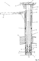
- the brake body 26 is part of an adjusting device 28, which is integrated in large parts in the center column 18 and controls the adjustment of the brake body 26 between the braking position and release position. Structure and function of the adjusting device 28 are described below with reference to the FIGS. 2 to 9 explained in more detail.
- Part of the adjusting device 28 is the gas spring 22, with a first part 30 and a second part 32, which are displaceable relative to each other in the axial direction and can be locked in a selected displacement position.
- Locking and Dearret ist done in a conventional manner by Actuation of a triggering element 34, in particular for opening or closing a gas valve of the gas spring 22.
- the triggering element 34 is preferably actuated in a manner known per se by movement of the first actuating lever 24 by the user so as to adjust the height of the chair 10.
- the first part 30 of the gas spring 22, here the cylinder of the gas spring 22, receives at its upper end the seat portion 12, so that acting from above on the seat portion 12 due to the weight of the user load force K acts in the downward direction on the first part 30 (see also FIG. 6 showing the loaded condition).
- the gas spring 22 is inserted into a cylindrical housing 38 of the center column, wherein preferably the first part 30 can rotate relative to the housing 38 about the main axis H and move along the main axis H.
- the second part 32 is coupled to a bearing 40 with a first adjusting element 42 such that the second part 32 can rotate relative to the first adjusting element 42 about the main axis H, but is held immovably in the axial direction on the first adjusting element 42.
- the first adjusting element 42 in turn is axially displaceable in the housing 38 and held rotatable about the main axis H. It can be accommodated as a sleeve, so that it also slidably and rotatably receives the first part 30 of the gas spring 22 in the retracted state of the gas spring 22.
- the first actuator 42 may be biased in the axial direction upwards. It will then be appreciated that upon application of a loading force K and locked gas spring 22, the second member 32 is moved in the downward direction, thereby moving the first actuator 42 down against the force of the first spring 44.
- the first actuator 42 In the downward direction Moving force transmitted to a brake actuator 46.
- the brake body 26 is attached or formed on the brake actuator 46.
- the brake control element 46 is preferably also held displaceably in the housing 38 of the center column 18 in the axial direction.
- a second spring 48 is provided, which biases the brake actuator 46 in the axial direction upwards and thus biases the brake body 26 in the release position.
- the axial support of the brake actuator 46 is exemplified such that a lower end of the second member 32 of the gas spring 22 is inserted into a central opening 50 of the brake actuator 46.
- the opening 50 is expanded in the interior of the brake actuator 46 to a spring chamber 52, in which the second spring 48 is received.
- the second spring 48 is then supported, on the one hand, on an inner wall of the spring chamber 52 adjacent to the edge of the opening 50 and, on the other hand, on a spring stop axially fixed at the end of the second part 32, for example a fixed disk 54.
- a movement of the brake actuator 46 may be limited by abutment of the brake actuator 46 on a housing-fixed stop 56.
- the first actuator 42 can transmit a motive force to the brake actuator 46 in the direction of the braking position or the power transmission is canceled.
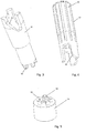
- a first toothing 58 can be seen on a lower end of the first actuating element 42 facing the brake actuating element 46, and a second toothing 60 on an upper end of the brake actuating element 46 facing the first actuating element 42.
- first actuating element 42 is set in such a rotational position that teeth the first teeth 58 teeth of the the second toothing 60 are opposite, ie the first toothing 58 and the second toothing 60 do not intermesh, so the first actuator 42 by contact contact of the axial end faces of the teeth 58, 60 pass the loading force K to the brake actuator 46 and so the brake body 26 on the Press underground U. If, on the other hand, the first adjusting element 42 is in such a rotational position that teeth of the first toothing 58 can engage in interdental spaces of the second toothing 60, the first adjusting element 42 and the brake actuating element 46 can continue to approach one another.
- the first actuator 42 regardless of the position of the brake actuator 46 due to the loading force K can move down until it abuts a housing fixed stop (for example, the housing fixed stop 56) and the loading force K thus in the housing and on the Housing in the foot section 14 and the rollers 16 is initiated.
- a housing fixed stop for example, the housing fixed stop 56
- the loading force K thus in the housing and on the Housing in the foot section 14 and the rollers 16 is initiated.
- the second spring 48 can be moved by the force of the second spring 48 in the upward direction by the repealed power transmission between the first actuator 42 and the brake actuator 46, the brake actuator 46, so that the brake body 26 lifts from the ground U.
- the brake is then in spite of the constant influence of the loading force K in the release position (see also FIG. 8 ).
- a brake release mechanism is realized in that the first actuator 42 is adjustable by rotation about the main axis H in such a position that the teeth 58, 60 can interlock and the brake actuator 46 is moved to release the brake upwards.
- the rotation of the first actuator 42 may be initiated by operation of a second actuator 62 by the user, such as using the actuating mechanism described below.
- an operating operation of the operating lever 62 is converted into an axial displacement of a second actuating element 64, which runs in the form of a sleeve around the main axis H around and is arranged above the first adjusting element 42.
- An actuation of the actuating lever 62 thus shifts the second actuating element 64 in the axial direction towards the first actuating element 42.
- the axial downward movement of the second control element 64 is converted into a forced rotational movement of the first control element 42.
- This motion conversion takes place by engagement of a first control cam 68 at the lower end of the second control element 64 in a second control curve 70 at the upper end of the first control element 42 (see. FIGS. 3 and 4 ).
- the cams 68, 70 which may be formed, for example, in the form of a coarse thread, are formed so that it upon rotation of the second actuating element 64 due to the actuation of the second actuating lever 62, a rotation of the first actuating element 42 to just about half of Tooth pitch (angular distance between two adjacent teeth) of the teeth 58 and 60 causes.
- a return mechanism ensures that the adjusting device 28 returns to the initial configuration according to FIG. 2 arrives.
- the first spring 44 raises the first actuator 42 back as part of the return mechanism in its upper position.
- the return mechanism rotates the first actuator 42 around the main axis H back to an initial position (reverse rotation) in which the teeth 58, 60 do not fit into each other, so that in the case of re-acting a loading force K, this force from the first actuator 42nd is transmitted to the brake actuator 46.
- this reverse rotation of the first actuator 42 different variants are conceivable.
- a torsion spring 72 may be provided, which on the one hand acts on the first adjusting element 42 and on the other hand held rotatably relative to the housing 38.
- the reverse rotation can also be taken over by the first spring 44, if one end of the first spring 44 is held against rotation on the first adjusting element 42 and the other end of the first spring 44 is held rotationally fixed with respect to the housing 38.
- An additional torsion spring can then be omitted and the first spring 44 acts both as a compression spring and as a torsion spring.
- the reverse rotation can be ensured by appropriate design of the control cams 68, 70 on the first and second control element 42, 64, for example, by the control cams are formed in the manner of a coarse thread and fit into each other to each other in both directions of rotation mutually force transfer.
- FIG. 2 shows the actuator of the chair 10 in an unloaded state, ie when no loading force K acts on the seat portion 12.
- the first spring 44 then holds the first actuator 42 in the upper position and the brake actuator 46 is also retracted to the upper position so that the brake body 26 does not brake the substrate U.
- the office chair 10 is then freely movable, for example. As soon as a user sits down on the office chair 10 or is leaning on it at an angle, it works a loading force K on the seat portion 12 on the gas spring 22 in the downward direction, as in FIG. 6 shown.
- first lever 36 is not actuated and first part 30 and second part 32 are immovably held each other
- first lever 36 is not actuated and first part 30 and second part 32 are immovably held each other
- first Actuator 42 moves down.
- the teeth of the first toothing 58 of the first adjusting element 42 are opposite the teeth of the second toothing 60 of the brake actuator 46 and form a force-transmitting abutment contact, so that the first actuator 42 presses the brake actuator 46 in the downward direction.
- the loading force K is thus passed through to the brake body 26 and pushes it against the ground U ( FIG. 6 ).
- the stronger the loading force K the greater the braking force through the brake body 26.
- FIG. 7 shows an intermediate position of this movement, in which the first actuator 42 is not fully rotated. But as soon as the tooth fit is reached, as in FIG.
- the abutting contact between the first actuator 42 and the brake actuator 46 is released and the first actuator 42 may continue to move downward until or insofar as it is not prevented by a stop on the housing-fixed stop 56 at a further downward movement.
- the loading force K is then over the housing-fixed stop 56 in the housing 38 and from this in the foot 14 of the chair 10 and the rollers 16 introduced.
- the above-mentioned tooth fit allows an upward movement of the brake actuator 46 and thus also of the brake body 26 by the action of the second spring 48 until the brake contact with the substrate U is canceled.
- the brake is then released and the chair 10 can be moved by rolling movement 16 along the ground U ( FIG. 8 ).
- the first spring 44 sets the first control element 42 in the axial direction back into the upper position.
- An intermediate state of this upward movement is in FIG. 9 illustrated.
- the return mechanism for example, the torsion spring 72 or the first spring 44
- the first actuator 42 back to its original position, in which teeth of the first teeth 58 teeth of the second gear 60 opposite, so that again the in FIG. 2 configured configuration is set.
- the chair 10 is thus now in the starting position and is ready for braking, so that upon renewed exposure to a loading force K, the brake body 26 is immediately returned to the braking position by the first control element 42.
- the invention is not limited to the embodiment described above.
- a rigid transmission from the seat portion 12 to the first control element 42 can take place or any other length adjustment mechanism can be used.
- the mechanism for the first actuator 42 for producing or dissolving the power transmission between the first actuator 42 and the brake actuator 46 is given above by way of example, but may be realized by other mechanisms. An electronic adjustment of both the coupling between the first actuator 42 and the brake actuator 46 and the height adjustment of the chair 10 can ins Be caught.
- the brake body 26 does not have to be supported directly on the ground U, but it can brake one or more of the rollers 16.
- the chair 10 may be configurable to be used on the one hand as a seat so that a user sits on the seat portion 12 and, on the other hand, is to be used as a standing aid so that a user can lean against the chair 10 in a standing position.
- an unrepresented Lehnabêt be mounted on the chair, which can support a person standing in the buttocks area.
- the reclining portion may be adjustable between a seat configuration in which a person sitting on the seat portion 12 can lean against the reclining portion with the back, and a standing configuration in which the reclining portion can support a user standing beside the chair 10 in the buttocks area. Accordingly, an adjustment of the chair 10 between the sitting and standing configuration can be made without adjusting the seat height of the chair 10.
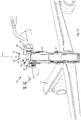
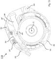
- FIG. 10 shows an actuator 128 of a chair as a mobile unit according to a second embodiment of the invention.
- the second embodiment is similar in many parts to the first embodiment and the same or corresponding elements or features are designated by 100 increased reference numerals.
- 100 increased reference numerals 100 increased reference numerals.
- an operating lever 162 which is provided for operating a brake release mechanism and in particular for releasing a brake member of the type described for the first embodiment, not at one with respect to a foot portion 114th solid housing but is rotatable with respect to the foot portion 114.
- the actuating lever 162 may be held on a lever axis 163 pivotally mounted on a switching ring 180 which is rotatably mounted about a main axis H of the adjusting element 128 to an actuating housing 182.
- Lever axis 163 and main axis H are at a distance parallel to each other.
- the actuating housing 182 can be connected in a rotationally fixed manner to a first part 130 of a gas spring 122; in particular, an inner side 184 of the actuating lever housing 182 can be fastened to an outer side 186 of the first part 130 of the gas spring 122 by a press fit.
- the actuating lever 162 moves during its pivotal movement about the lever axis 163 provided on the actuating lever 162 jaw body 187 with a toothed claw 188 in the direction of a latching engagement with an external toothing of a shift sleeve 189 or out of this locking engagement. If the claw 188 and the shift sleeve 189 in the latching engagement, then a further movement of the actuating lever 162 in FIG.
- a first spring 190 may bias the operating lever with respect to its pivoting movement about the lever axis 163 in the direction of releasing the locking engagement between the claw 188 and the switching sleeve 189, counterclockwise then to a common rotational movement of actuating lever 162, switching ring 180 and switching sleeve 189 about the major axis H. so that a removal of the actuating force by the user pivots back the actuating lever 162 about the lever axis 163.
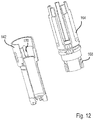
- the claw 188 may be fixedly attached to the claw body 187 or alternatively as in FIG FIG. 11 shown coupled via an overload device on the jaw body 187.
- the overload device is realized in that the claw 188 is mounted with limited play movable on the jaw body 187 and is biased by a second spring 191 in the direction of the shift sleeve 189.
- the game is big enough for that Disconnect teeth of claw 188 and shift sleeve 189 against the force of the second spring 191 disengaged when in a state in which the actuating lever 162 counterclockwise in FIG.
- the rotational movement of the shift sleeve 189 is converted into a rotational movement of a first actuating element 142, which is responsible in a corresponding manner, as described above for the first embodiment, as part of the brake release mechanism for releasing a brake by lifting a brake actuator.
- a second actuator 164 is provided, which is arranged coaxially with the first actuator 142 and rotatably, but axially displaceable, with the first actuator 142 is coupled, for example, by engagement of an axial rib 168 of the second actuator 164 in an axial longitudinal opening 170 of the first control element 142.
- the second control element 164 is in turn rotatably connected to the shift sleeve 189 or formed integrally therewith.
- the operation of the adjusting element 128 differs from that of the first embodiment substantially by the above-described arrangement and function of the operating lever 162, in particular by the fact that the actuating lever 162 remains stationary in its initial position (without actuation) relative to the seat portion (load input portion), that is rotates with a rotation of the seat portion with and also in a height adjustment of the seat portion is moved together with the seat portion in the vertical direction.
- the actuating housing 182, which carries the actuating lever 162 is non-rotatably connected to the first part 130 of the gas spring 122, to which also the seat portion is to be fastened (although the seat portion in FIG FIG. 10 not shown, but so for example on FIGS.
- the first part 130 of the gas spring 122 is longitudinally displaceably guided in a guide sleeve and rotatably guided to allow an adjustment of the seat height and a rotation of the seat.
- the operating lever 162 thus rotates and rises together with the seat and is always accessible to the user at the same position.
- Figures 13 and 14 show a third embodiment of the invention, which represents a variant of the second embodiment. Elements and features which are the same as or correspond to those of the first or second embodiment are designated by references 200 and 100, respectively. In the following, only the differences to the first or second embodiment will be discussed in more detail and reference is otherwise made to the above descriptions of the first or second embodiment.
- a Bowden cable arrangement with a pull cable 292, which is guided in a cable guide 293, takes the place of the actuating lever 162 of the second exemplary embodiment.
- the cable guide 293 is fixedly provided on an actuating housing 282, which in turn can be formed in the manner described above for the second embodiment and attached to a first part of a gas spring, so that it can rotate with a seat portion.
- An end body 294 of the traction cable 292 is hooked into a claw body 287, which corresponds in its other design and function of the claw body 187 of the second embodiment, in particular about a lever axis 263 is pivotally provided in a switching ring 280.
- the switching ring 280 is in turn in the manner described in the second embodiment about a control axis H rotatably mounted on the actuator housing 282.
- actuated position pulls the pull cable 292 then the jaw body 287 on and causes a common rotational movement of jaw body 287, jaw 288, shift ring 280 and shift sleeve 289 to the adjusting axis H to release the brake.
- a return spring 295 rotates the shift ring 280 and the pawl body back to their original positions.
- the flexibility of length and path of the Bowden cable can be used to position an actuator (not shown), via which the Bowden cable assembly is actuated, to a suitable position of the chair, which is easily accessible to the user.
- the actuating element may be arranged on a seat device.
- the function of the actuator assembly of the third embodiment is similar to that of the first or second embodiment.
Landscapes
- Braking Arrangements (AREA)
Applications Claiming Priority (2)
| Application Number | Priority Date | Filing Date | Title |
|---|---|---|---|
| DE102016220881 | 2016-10-24 | ||
| DE102017208151.1A DE102017208151A1 (de) | 2016-10-24 | 2017-05-15 | Stellvorrichtung zur Betätigung einer Bremse und mobile Einheit, insbesondere Stuhl |
Publications (1)
| Publication Number | Publication Date |
|---|---|
| EP3311703A1 true EP3311703A1 (fr) | 2018-04-25 |
Family
ID=60162062
Family Applications (1)
| Application Number | Title | Priority Date | Filing Date |
|---|---|---|---|
| EP17197815.8A Withdrawn EP3311703A1 (fr) | 2016-10-24 | 2017-10-23 | Dispositif de réglage permettant d'actionner un frein et unité mobile, en particulier chaise |
Country Status (1)
| Country | Link |
|---|---|
| EP (1) | EP3311703A1 (fr) |
Cited By (2)
| Publication number | Priority date | Publication date | Assignee | Title |
|---|---|---|---|---|
| WO2019158159A1 (fr) * | 2018-02-14 | 2019-08-22 | Kinema Gmbh | Meuble d'assise et de support |
| DE102018129990A1 (de) * | 2018-11-27 | 2020-05-28 | Goracon Engineering Gmbh | Stuhlführung |
Citations (4)
| Publication number | Priority date | Publication date | Assignee | Title |
|---|---|---|---|---|
| DE2256336A1 (de) * | 1972-11-16 | 1974-05-22 | Siemens Ag | Fahrbarer arbeitsstuhl, insbesondere fuer zahnaerzte |
| DE3041926A1 (de) * | 1980-11-06 | 1982-06-09 | Manne Borås Lanner | Stuhl |
| US4434808A (en) * | 1982-06-18 | 1984-03-06 | Burak Mark G | Anti-skid device for a cane, crutch, or the like |
| DE102008009413A1 (de) * | 2008-02-15 | 2009-08-20 | Fraunhofer-Gesellschaft zur Förderung der angewandten Forschung e.V. | Stuhlfuß mit Rollsperre |
-
2017
- 2017-10-23 EP EP17197815.8A patent/EP3311703A1/fr not_active Withdrawn
Patent Citations (4)
| Publication number | Priority date | Publication date | Assignee | Title |
|---|---|---|---|---|
| DE2256336A1 (de) * | 1972-11-16 | 1974-05-22 | Siemens Ag | Fahrbarer arbeitsstuhl, insbesondere fuer zahnaerzte |
| DE3041926A1 (de) * | 1980-11-06 | 1982-06-09 | Manne Borås Lanner | Stuhl |
| US4434808A (en) * | 1982-06-18 | 1984-03-06 | Burak Mark G | Anti-skid device for a cane, crutch, or the like |
| DE102008009413A1 (de) * | 2008-02-15 | 2009-08-20 | Fraunhofer-Gesellschaft zur Förderung der angewandten Forschung e.V. | Stuhlfuß mit Rollsperre |
Cited By (4)
| Publication number | Priority date | Publication date | Assignee | Title |
|---|---|---|---|---|
| WO2019158159A1 (fr) * | 2018-02-14 | 2019-08-22 | Kinema Gmbh | Meuble d'assise et de support |
| US11937708B2 (en) | 2018-02-14 | 2024-03-26 | Mykinema Gmbh | Seating and support furniture |
| DE102018129990A1 (de) * | 2018-11-27 | 2020-05-28 | Goracon Engineering Gmbh | Stuhlführung |
| DE102018129990B4 (de) | 2018-11-27 | 2024-02-01 | Goracon Engineering Gmbh | Stuhlführung |
Similar Documents
| Publication | Publication Date | Title |
|---|---|---|
| WO2015040008A1 (fr) | Siège | |
| EP2374657A2 (fr) | Accoudoir et poste de commande doté d'un tel accoudoir | |
| EP2227403B1 (fr) | Dispositif de verrouillage, notamment pour un appuie-tête anti-crash actif d'un véhicule | |
| WO2014075819A1 (fr) | Siège de véhicule, en particulier siège de véhicule automobile | |
| DE102017208151A1 (de) | Stellvorrichtung zur Betätigung einer Bremse und mobile Einheit, insbesondere Stuhl | |
| DE2359311C3 (de) | Teleskopträger | |
| EP3038855A1 (fr) | Armature équipée d'un mécanisme de pivotement en avant et d'un cliquet d'accès facile ainsi que siège de véhicule équipé d'une telle armature | |
| EP3672451B1 (fr) | Chaise avec un élément de libération | |
| DE102016117509B4 (de) | Armlehne sowie Rückenlehne für einen Fahrzeugsitz und Fahrzeugsitz | |
| EP3752027B1 (fr) | Meuble d'assise et de support | |
| DE102007044561A1 (de) | Antriebsvorrichtung für eine Verstelleinrichtung eines Kraftfahrzeugs | |
| EP3342387B1 (fr) | Dispositif de protection d'une personne occupant un lit contre les chutes d'un lit, en particulier d'un lit de soins et lit, en particulier lit de soins doté d'un dispositif de protection | |
| DE2605522A1 (de) | Schwenkbarer sitzbeschlag | |
| EP1075981B1 (fr) | Dispositif de blocage pour un siège de véhicule | |
| DE19922446B4 (de) | Synchronmechanik für eine korrelierte Sitz-Rückenlehnen-Bewegung eines Bürostuhles | |
| DE102011109668A1 (de) | Sitzmöbel mit verstellbarer Kopfstütze | |
| DE102008056290A1 (de) | Ausstattungsteil für Fahrzeuge | |
| DE102010054753B4 (de) | Verschiebbare Armauflage für Fahrzeuge | |
| DE102012108157B3 (de) | Schienenfahrzeug mit einer Schiebetür und Schienenfahrzeugwagen mit einer WC-Einheit | |
| DE2108718A1 (de) | Sicherheitsgurt | |
| DE102014213166A1 (de) | Fahrzeugsitz mit Rastvorrichtung und zusätzlicher Steuereinrichtung | |
| EP2446781A1 (fr) | Chaise | |
| DE102005027052B4 (de) | Sitzversteller | |
| DE102005020696A1 (de) | Verstelleinrichtung für ein Kraftfahrzeug | |
| EP2571472A1 (fr) | Meuble d'assise |
Legal Events
| Date | Code | Title | Description |
|---|---|---|---|
| PUAI | Public reference made under article 153(3) epc to a published international application that has entered the european phase |
Free format text: ORIGINAL CODE: 0009012 |
|
| STAA | Information on the status of an ep patent application or granted ep patent |
Free format text: STATUS: THE APPLICATION HAS BEEN PUBLISHED |
|
| AK | Designated contracting states |
Kind code of ref document: A1 Designated state(s): AL AT BE BG CH CY CZ DE DK EE ES FI FR GB GR HR HU IE IS IT LI LT LU LV MC MK MT NL NO PL PT RO RS SE SI SK SM TR |
|
| AX | Request for extension of the european patent |
Extension state: BA ME |
|
| STAA | Information on the status of an ep patent application or granted ep patent |
Free format text: STATUS: REQUEST FOR EXAMINATION WAS MADE |
|
| 17P | Request for examination filed |
Effective date: 20181025 |
|
| RBV | Designated contracting states (corrected) |
Designated state(s): AL AT BE BG CH CY CZ DE DK EE ES FI FR GB GR HR HU IE IS IT LI LT LU LV MC MK MT NL NO PL PT RO RS SE SI SK SM TR |
|
| STAA | Information on the status of an ep patent application or granted ep patent |
Free format text: STATUS: EXAMINATION IS IN PROGRESS |
|
| 17Q | First examination report despatched |
Effective date: 20190502 |
|
| GRAP | Despatch of communication of intention to grant a patent |
Free format text: ORIGINAL CODE: EPIDOSNIGR1 |
|
| STAA | Information on the status of an ep patent application or granted ep patent |
Free format text: STATUS: GRANT OF PATENT IS INTENDED |
|
| INTG | Intention to grant announced |
Effective date: 20191212 |
|
| STAA | Information on the status of an ep patent application or granted ep patent |
Free format text: STATUS: THE APPLICATION IS DEEMED TO BE WITHDRAWN |
|
| 18D | Application deemed to be withdrawn |
Effective date: 20200603 |