EP3311952A1 - Ausgeglichene drehbearbeitung - Google Patents
Ausgeglichene drehbearbeitung Download PDFInfo
- Publication number
- EP3311952A1 EP3311952A1 EP17190529.2A EP17190529A EP3311952A1 EP 3311952 A1 EP3311952 A1 EP 3311952A1 EP 17190529 A EP17190529 A EP 17190529A EP 3311952 A1 EP3311952 A1 EP 3311952A1
- Authority
- EP
- European Patent Office
- Prior art keywords
- enclosed channel
- fixture
- rotational axis
- balancing substance
- spindle
- Prior art date
- Legal status (The legal status is an assumption and is not a legal conclusion. Google has not performed a legal analysis and makes no representation as to the accuracy of the status listed.)
- Withdrawn
Links
- 238000003754 machining Methods 0.000 title claims description 12
- 239000000126 substance Substances 0.000 claims abstract description 47
- 239000012530 fluid Substances 0.000 claims description 18
- 238000000034 method Methods 0.000 claims description 18
- 239000002245 particle Substances 0.000 claims description 7
- 239000007787 solid Substances 0.000 claims description 7
- 239000011324 bead Substances 0.000 claims description 4
- 229920000642 polymer Polymers 0.000 claims description 3
- WFKWXMTUELFFGS-UHFFFAOYSA-N tungsten Chemical compound [W] WFKWXMTUELFFGS-UHFFFAOYSA-N 0.000 claims description 3
- 229910052721 tungsten Inorganic materials 0.000 claims description 3
- 239000010937 tungsten Substances 0.000 claims description 3
- XLYOFNOQVPJJNP-UHFFFAOYSA-N water Substances O XLYOFNOQVPJJNP-UHFFFAOYSA-N 0.000 claims description 3
- 230000000712 assembly Effects 0.000 description 8
- 238000000429 assembly Methods 0.000 description 8
- 230000008901 benefit Effects 0.000 description 6
- 230000010355 oscillation Effects 0.000 description 4
- 239000000463 material Substances 0.000 description 3
- 239000002826 coolant Substances 0.000 description 2
- 230000008878 coupling Effects 0.000 description 2
- 238000010168 coupling process Methods 0.000 description 2
- 238000005859 coupling reaction Methods 0.000 description 2
- 238000010586 diagram Methods 0.000 description 2
- 230000000694 effects Effects 0.000 description 2
- 230000000977 initiatory effect Effects 0.000 description 2
- 239000007788 liquid Substances 0.000 description 2
- 239000000314 lubricant Substances 0.000 description 2
- 230000006978 adaptation Effects 0.000 description 1
- 230000003466 anti-cipated effect Effects 0.000 description 1
- 238000010276 construction Methods 0.000 description 1
- 238000012544 monitoring process Methods 0.000 description 1
- 239000002994 raw material Substances 0.000 description 1
- 230000003068 static effect Effects 0.000 description 1
Images



Classifications
-
- F—MECHANICAL ENGINEERING; LIGHTING; HEATING; WEAPONS; BLASTING
- F16—ENGINEERING ELEMENTS AND UNITS; GENERAL MEASURES FOR PRODUCING AND MAINTAINING EFFECTIVE FUNCTIONING OF MACHINES OR INSTALLATIONS; THERMAL INSULATION IN GENERAL
- F16F—SPRINGS; SHOCK-ABSORBERS; MEANS FOR DAMPING VIBRATION
- F16F15/00—Suppression of vibrations in systems; Means or arrangements for avoiding or reducing out-of-balance forces, e.g. due to motion
- F16F15/32—Correcting- or balancing-weights or equivalent means for balancing rotating bodies, e.g. vehicle wheels
- F16F15/36—Correcting- or balancing-weights or equivalent means for balancing rotating bodies, e.g. vehicle wheels operating automatically, i.e. where, for a given amount of imbalance, there is movement of masses until balance is achieved
- F16F15/366—Correcting- or balancing-weights or equivalent means for balancing rotating bodies, e.g. vehicle wheels operating automatically, i.e. where, for a given amount of imbalance, there is movement of masses until balance is achieved using fluid or powder means, i.e. non-discrete material
-
- B—PERFORMING OPERATIONS; TRANSPORTING
- B23—MACHINE TOOLS; METAL-WORKING NOT OTHERWISE PROVIDED FOR
- B23B—TURNING; BORING
- B23B3/00—General-purpose turning-machines or devices, e.g. centre lathes with feed rod and lead screw; Sets of turning-machines
-
- B—PERFORMING OPERATIONS; TRANSPORTING
- B23—MACHINE TOOLS; METAL-WORKING NOT OTHERWISE PROVIDED FOR
- B23Q—DETAILS, COMPONENTS, OR ACCESSORIES FOR MACHINE TOOLS, e.g. ARRANGEMENTS FOR COPYING OR CONTROLLING; MACHINE TOOLS IN GENERAL CHARACTERISED BY THE CONSTRUCTION OF PARTICULAR DETAILS OR COMPONENTS; COMBINATIONS OR ASSOCIATIONS OF METAL-WORKING MACHINES, NOT DIRECTED TO A PARTICULAR RESULT
- B23Q11/00—Accessories fitted to machine tools for keeping tools or parts of the machine in good working condition or for cooling work; Safety devices specially combined with or arranged in, or specially adapted for use in connection with, machine tools
- B23Q11/0032—Arrangements for preventing or isolating vibrations in parts of the machine
- B23Q11/0035—Arrangements for preventing or isolating vibrations in parts of the machine by adding or adjusting a mass, e.g. counterweights
-
- F—MECHANICAL ENGINEERING; LIGHTING; HEATING; WEAPONS; BLASTING
- F16—ENGINEERING ELEMENTS AND UNITS; GENERAL MEASURES FOR PRODUCING AND MAINTAINING EFFECTIVE FUNCTIONING OF MACHINES OR INSTALLATIONS; THERMAL INSULATION IN GENERAL
- F16F—SPRINGS; SHOCK-ABSORBERS; MEANS FOR DAMPING VIBRATION
- F16F15/00—Suppression of vibrations in systems; Means or arrangements for avoiding or reducing out-of-balance forces, e.g. due to motion
- F16F15/32—Correcting- or balancing-weights or equivalent means for balancing rotating bodies, e.g. vehicle wheels
- F16F15/36—Correcting- or balancing-weights or equivalent means for balancing rotating bodies, e.g. vehicle wheels operating automatically, i.e. where, for a given amount of imbalance, there is movement of masses until balance is achieved
- F16F15/363—Correcting- or balancing-weights or equivalent means for balancing rotating bodies, e.g. vehicle wheels operating automatically, i.e. where, for a given amount of imbalance, there is movement of masses until balance is achieved using rolling bodies, e.g. balls free to move in a circumferential direction
-
- B—PERFORMING OPERATIONS; TRANSPORTING
- B23—MACHINE TOOLS; METAL-WORKING NOT OTHERWISE PROVIDED FOR
- B23B—TURNING; BORING
- B23B2250/00—Compensating adverse effects during turning, boring or drilling
- B23B2250/04—Balancing rotating components
-
- F—MECHANICAL ENGINEERING; LIGHTING; HEATING; WEAPONS; BLASTING
- F16—ENGINEERING ELEMENTS AND UNITS; GENERAL MEASURES FOR PRODUCING AND MAINTAINING EFFECTIVE FUNCTIONING OF MACHINES OR INSTALLATIONS; THERMAL INSULATION IN GENERAL
- F16F—SPRINGS; SHOCK-ABSORBERS; MEANS FOR DAMPING VIBRATION
- F16F2230/00—Purpose; Design features
- F16F2230/0011—Balancing, e.g. counterbalancing to produce static balance
-
- F—MECHANICAL ENGINEERING; LIGHTING; HEATING; WEAPONS; BLASTING
- F16—ENGINEERING ELEMENTS AND UNITS; GENERAL MEASURES FOR PRODUCING AND MAINTAINING EFFECTIVE FUNCTIONING OF MACHINES OR INSTALLATIONS; THERMAL INSULATION IN GENERAL
- F16F—SPRINGS; SHOCK-ABSORBERS; MEANS FOR DAMPING VIBRATION
- F16F2232/00—Nature of movement
- F16F2232/02—Rotary
Definitions
- the present disclosure relates to rotary assemblies, and more specifically, to balancing rotary assemblies.
- the present disclosure provides an apparatus that includes a rotatable part configured to rotate about a rotational axis and an enclosed channel that is coupled to the rotatable part.
- the enclosed channel may circumscribe the rotational axis and may be configured to contain a balancing substance that is freely movable within the enclosed channel.
- the balancing substance includes at least one of an incompressible fluid and a plurality of solid particles.
- the balancing substance includes a plurality of tungsten polymer beads and/or ball bearings.
- the balancing substance includes water.
- the balancing substance includes an operating fluid of the rotatable part, such as, for example, a hydraulic fluid or an oil.
- the enclosed channel is integrated with the rotatable part while in various other embodiment the enclosed channel is mounted externally to the rotatable part.
- the enclosed channel may be substantially concentric with the rotational axis.
- the enclosed channel extends in a circular shape around the rotational axis.
- the circular shape may be substantially perpendicular to the rotational axis.
- the enclosed channel has a circular cross-section.
- the vertical turning machine may include a spindle configured to rotate about a rotational axis, a fixture coupled to the spindle, and an enclosed channel coupled to at least one of the spindle and the fixture.
- the fixture may include at least one mounting feature configured to secure a workpiece to be machined to the fixture and the enclosed channel may circumscribe the rotational axis.
- the enclosed channel may also be configured to contain a balancing substance that is freely movable within the enclosed channel.
- the balancing substance includes least one of an incompressible fluid and a plurality of solid particles.
- the balancing substance may include an operating fluid of the vertical turning machine.
- the enclosed channel extends in a circular shape around the rotational axis. In various embodiments, the circular shape may be substantially horizontal.
- a method of machining a workpiece includes, according to various embodiments, securing the workpiece to a fixture (the fixture may be coupled to a spindle), wherein an enclosed channel containing a balancing substance is coupled to at least one of the spindle, the fixture, and the workpiece.
- the method may further include rotating the spindle, which causes the balancing substance contained within the enclosed channel to distribute throughout the enclosed channel to balance rotation of the workpiece, the fixture, and the spindle.
- imbalanced rotary assemblies can have negative consequences.
- an imbalanced rotary assembly can result in reduced operating efficiency and/or a reduced useable life of the rotary assembly.
- imbalanced operation of a rotary assembly may negatively affect the accuracy and precision of machining results on a subject work piece.
- the apparatus 100 of the present disclosure enables rotary assemblies to automatically achieve dynamic balanced rotation.
- the apparatus 100 may include a rotatable part 110 and an enclosed channel 120.
- the rotatable part 110 is configured to rotate about a rotational axis.
- the rotatable part 110 may be any component or element that rotates about a rotational axis.
- the rotatable part 110 may be a spindle, a rotary fixture, a rotary tool, or a rotary tool holder, among others.
- the enclosed channel 120 may be coupled to the rotatable part 110 and may circumscribe the rotational axis.
- enclosed channel refers to a closed tube that extends around a rotational axis of the rotatable part 110.
- the enclosed channel 120 may be an enclosed conduit, tube, pipe, etc., that forms an annular structure around the rotational axis.
- the term “enclosed” does not refer to the position of the channel relative to other components, but instead refers to a closed chamber.
- Contained within the enclosed channel 120 is a balancing substance that is freely movable within the enclosed channel 120. Additional details pertaining to the rotatable part 110, the enclosed channel 120, and the balancing substance are included below.
- the enclosed channel 120 rotates with the rotatable part 110 to which it is coupled, according to various embodiments.
- the balancing substance contained within the enclosed channel 120 which is free-moving relative to the enclosed channel 120, distributes throughout the enclosed channel to offset rotational imbalances, according to various embodiments.
- the balancing substance may disperse throughout the enclosed channel 120 to occupy one or more positions in the rotating enclosed channel 120 that correspond with one or more portions of the rotatable part 110 that has comparatively less mass (e.g., less dense portions of the entire rotating body of the apparatus 100).
- the rotatable part 110 does not have the enclosed channel 120 coupled thereto and if one side or one portion of the rotatable part 110 has less mass than other sides or portions, the center of mass of the rotatable part 110 would not be aligned with the rotational axis and thus the apparatus 100 would be imbalanced, thereby resulting in vibrations or oscillations during operation.
- the combined center of mass is the position/location where the combined weighted relative position of the distributed mass sums to zero.
- the apparatus 100 is able to achieve a stable, balanced operating condition over a wide range of rotational speeds.
- the balancing substance being freely moveable within and through the enclosed channel 120, distributes itself, in response to rotation, along the enclosed channel 120 to dynamically maintain the combined center of mass of the apparatus 100 (including any parts, workpieces, or fixtures that rotate with the apparatus 100) substantially aligned with the rotational axis, thereby tending to correct imbalances and maintaining a stable, balanced rotational motion.
- the distribution of the balancing substance through the enclosed channel 120 enables the rotary motion to remain balanced despite changes to the combined center of mass caused by machine wear and/or by the effect of the machining process on the workpiece.
- the combined center of mass of the apparatus 100 may not be aligned with the rotational axis when the rotatable part 110 is not in motion
- the automatic distribution of the balancing substance through the enclosed channel 120 in response to the rotary motion balances the rotary motion.
- the balancing substance is distributed through the enclosed channel 120 to eliminate, or at least reduce, imbalance of the rotatable part 110 in response to initiation of rotation of the rotatable part 110, or at least before the angular rotation speed reaches a threshold.
- the apparent centrifugal force may have a dominant effect on the balancing substance and thus the balancing substance may be limited in its ability to dynamically circumferentially distribute to correct rotational imbalances.
- the balancing substance may be able to circumferentially distribute itself to counterbalance the imbalance.
- a portion of the rotatable part 110 may have a comparatively greater mass (e.g., a 'heavy spot').
- inertia of the balancing substance may resist the apparent oscillation of the rotatable part 110 caused by the 'heavy spot' and thus the balancing substance may inertially distribute away from the apparent oscillation of the 'heavy spot.”
- the rotatable part 110 and the enclosed channel 120 may be configured to rotate up to about 2,000 rotations per minute ("RPM"). In various embodiments, for example when the rotatable part 110 is a rotary tool or a rotary tool holder, the rotatable part 110 and the enclosed channel 120 may be configured to rotate up to between about 20,000 rotations per minute and about 60,000 rotations per minute.
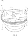
- a vertical turning machine 200 is disclosed. As mentioned above, like reference numbers refer to like elements. Accordingly, the vertical turning machine 200 is one implementation of the apparatus 100. That is, the vertical turning machine 200 disclosed herein is but one example, of many, of how the subject matter described above with reference to FIG. 1 can be implemented. Therefore, the scope of the present disclosure is not limited to fixture-devices akin to the vertical turning machine 200 described herein, but the subject matter of the present disclosure may be applicable to various types of rotatable parts, such as spindles, rotary fixtures, rotary tools, rotary tool holders, etc.
- the vertical turning machine 200 includes, according to various embodiments, a spindle 212, a fixture 214, and an enclosed channel 220.
- the vertical turning machine 200 may be used to mill, cut, or otherwise machine a workpiece 216 (e.g., a raw material) that is coupled to the fixture 214.
- the spindle 212 may be operably coupled to a motor or other power source and may be configured to rotate about a rotational axis.
- the fixture 214 is coupled to the spindle 212 and thus is configured to co-rotate with the spindle 212 about the rotational axis.
- the workpiece 216 may be coupled to the fixture 214 via one or more mounting features 215 and thus may be configured to also co-rotate with the spindle 212 and the fixture 214.
- the enclosed channel 220 may be coupled to any of the rotatable components, such as the spindle 212, the fixture 214, or even the workpiece 216 itself.
- the combined center of mass of the vertical turning machine 200 including the spindle 212, the fixture 214, the workpiece 216, and the enclosed channel 220, may not be aligned with the rotational axis and thus may appear to be imbalanced.
- the balancing substance in the enclosed channel may be distributed through the enclosed channel 220 to cure the imbalance and maintain a stable, balanced rotary motion over a range of rotating speeds.
- the balanced rotary motion of the apparatus 200 enables the work-piece to be precisely and accurately machined (e.g., milled, cut, etc.) because the enclosed channel 220, with its contained balancing substance, prevents vibrations and imbalanced-induced oscillations.
- the enclosed channel 120 may be mounted externally to the rotatable part 110.
- the enclosed channel 220 may be mounted to the spindle 212, the fixture 214, and/or the workpiece 216.
- the enclosed channel 420 may be mounted within the rotatable part or may be integrally formed (machined, cast, etc.) in the rotatable part.
- the enclosed channel 420 of the apparatus 400 shown in FIG. 4 may be integrated in the fixture 414 of the apparatus 400.
- the enclosed channel 420 may be integrated formed in the spindle 212 and/or the fixture 214.
- the enclosed channel 120 is substantially concentric with the rotational axis of the apparatus 100. In various other embodiments, the enclosed channel 120 may not be concentric with the rotational axis of the apparatus 100. In various embodiments, the enclosed channel 120 may extend in a circular shape around the rotational axis of the apparatus 100. The circular shape may be perpendicular to the rotational axis of the apparatus 100, according to various embodiments. In various embodiments, the shape of the enclosed channel 120 extending around the rotational axis of the apparatus 100 is non-uniform.
- the perimeter of the enclosed channel 120 may not be radially equidistant from the rotational axis and yet the balancing substance contained within the enclosed channel 120 may still balance the rotary movement of the apparatus 100.
- the cross-section of the enclosed channel 120 may be circular (e.g., tube-like). In various other embodiments, the cross-section of the enclosed channel 120 may be oval, obround, or rectangular, among others.
- the balancing substance is an incompressible fluid and/or a plurality of solid particles.
- the incompressible fluid may be water or an operating fluid/liquid used in conjunction with the apparatus 100, among other liquids.
- the balancing substance may be hydraulic fluid, lubricant, coolant, and/or oil used in conjunction with the rotatable part 110.
- hydraulic fluid, lubricant, coolant, and/or oil from the motor or power source that drives rotation of the rotatable part 110 may be utilized in the enclosed channel 120 as the balancing substance.
- the incompressible fluid may be selected according to the material properties of the enclosed channel 120 so as to not corrode or otherwise deteriorate the structure of the enclosed channel 120.
- the enclosed channel may include a plurality of solid particles, such as ball bearings, beads, etc.
- the plurality of solid particles is a plurality of tungsten polymer beads.
- the mass of the balancing substance may be selected according to the expected/anticipated combined mass of the apparatus 100.
- the mass of the balancing substance contained within the enclosed channel 120 may be proportional to the combined mass and/or the position of the combined center of mass of the apparatus 100 relative to the rotational axis.
- the apparatus 100 may include more than one enclosed channel 120.
- a method 590 of machining a workpiece includes, according to various embodiments, securing the workpiece to a fixture at step 592.
- the fixture may be coupled to a spindle, which is operably coupled to a motor or other power source.
- An enclosed channel containing a balancing substance is also coupled to one or more of the fixture, the spindle, and the workpiece.
- the method 590 may further include rotating the spindle at step 594.
- Step 594 causes the balancing substance contained within the enclosed channel to automatically distribute throughout the enclosed channel to balance the rotation of the rotating components (e.g., the spindle, the fixture, and the workpiece).
- any reference to attached, fixed, connected, coupled or the like may include permanent (e.g., integral), removable, temporary, partial, full, and/or any other possible attachment option.
- permanent e.g., integral
- removable temporary, partial, full
- any other possible attachment option e.g., permanent, temporary, partial, full, and/or any other possible attachment option.
- Different cross-hatching is used throughout the figures to denote different parts but not necessarily to denote the same or different materials.
- any of the method or process descriptions may be executed in any order and are not necessarily limited to the order presented.
- any reference to singular includes plural embodiments, and any reference to more than one component or step may include a singular embodiment or step.
- Elements and steps in the figures are illustrated for simplicity and clarity and have not necessarily been rendered according to any particular sequence. For example, steps that may be performed concurrently or in different order are illustrated in the figures to help to improve understanding of embodiments of the present disclosure.
- Any reference to attached, fixed, connected or the like may include permanent, removable, temporary, partial, full and/or any other possible attachment option. Additionally, any reference to without contact (or similar phrases) may also include reduced contact or minimal contact. Surface shading lines may be used throughout the figures to denote different parts or areas but not necessarily to denote the same or different materials. In some cases, reference coordinates may be specific to each figure.
- references to "one embodiment”, “an embodiment”, “various embodiments”, etc. indicate that the embodiment described may include a particular feature, structure, or characteristic, but every embodiment may not necessarily include the particular feature, structure, or characteristic. Moreover, such phrases are not necessarily referring to the same embodiment. Further, when a particular feature, structure, or characteristic is described in connection with an embodiment, it is submitted that it is within the knowledge of one skilled in the art to affect such feature, structure, or characteristic in connection with other embodiments whether or not explicitly described. After reading the description, it will be apparent to one skilled in the relevant art(s) how to implement the disclosure in alternative embodiments.
Landscapes
- Engineering & Computer Science (AREA)
- General Engineering & Computer Science (AREA)
- Mechanical Engineering (AREA)
- Physics & Mathematics (AREA)
- Acoustics & Sound (AREA)
- Aviation & Aerospace Engineering (AREA)
- Constituent Portions Of Griding Lathes, Driving, Sensing And Control (AREA)
Applications Claiming Priority (1)
| Application Number | Priority Date | Filing Date | Title |
|---|---|---|---|
| US15/297,498 US20180106325A1 (en) | 2016-10-19 | 2016-10-19 | Balanced rotational machining |
Publications (1)
| Publication Number | Publication Date |
|---|---|
| EP3311952A1 true EP3311952A1 (de) | 2018-04-25 |
Family
ID=59887030
Family Applications (1)
| Application Number | Title | Priority Date | Filing Date |
|---|---|---|---|
| EP17190529.2A Withdrawn EP3311952A1 (de) | 2016-10-19 | 2017-09-12 | Ausgeglichene drehbearbeitung |
Country Status (2)
| Country | Link |
|---|---|
| US (1) | US20180106325A1 (de) |
| EP (1) | EP3311952A1 (de) |
Citations (4)
| Publication number | Priority date | Publication date | Assignee | Title |
|---|---|---|---|---|
| DE7104765U (de) * | 1971-02-09 | 1971-08-19 | Bruins D | |
| GB1303813A (de) * | 1969-05-22 | 1973-01-24 | ||
| US5758555A (en) * | 1996-05-01 | 1998-06-02 | J.R. Engineering | Vertical turning machine |
| FR3032766A1 (fr) * | 2015-02-13 | 2016-08-19 | Amnc Innovations | Dispositif d’equilibrage pour une machine a tambour rotatif et machine comprenant un tambour rotatif equipe d’un tel dispositif |
Family Cites Families (1)
| Publication number | Priority date | Publication date | Assignee | Title |
|---|---|---|---|---|
| US6979060B2 (en) * | 2003-07-18 | 2005-12-27 | Fogal Sr Robert D | Balance weight cartridge with enclosed balance media |
-
2016
- 2016-10-19 US US15/297,498 patent/US20180106325A1/en not_active Abandoned
-
2017
- 2017-09-12 EP EP17190529.2A patent/EP3311952A1/de not_active Withdrawn
Patent Citations (4)
| Publication number | Priority date | Publication date | Assignee | Title |
|---|---|---|---|---|
| GB1303813A (de) * | 1969-05-22 | 1973-01-24 | ||
| DE7104765U (de) * | 1971-02-09 | 1971-08-19 | Bruins D | |
| US5758555A (en) * | 1996-05-01 | 1998-06-02 | J.R. Engineering | Vertical turning machine |
| FR3032766A1 (fr) * | 2015-02-13 | 2016-08-19 | Amnc Innovations | Dispositif d’equilibrage pour une machine a tambour rotatif et machine comprenant un tambour rotatif equipe d’un tel dispositif |
Also Published As
| Publication number | Publication date |
|---|---|
| US20180106325A1 (en) | 2018-04-19 |
Similar Documents
| Publication | Publication Date | Title |
|---|---|---|
| KR0139924B1 (ko) | 회전 공구 조립체의 평형을 잡기 위한 방법 및 장치 | |
| KR101695334B1 (ko) | 유체 동력 스핀들 | |
| US6974362B2 (en) | System and method for automatically compensating for unbalanced resistance forces | |
| WO2002097263A2 (en) | Balancing assembly for a rotating member | |
| CN103252672A (zh) | 心轴组件 | |
| RU2469831C2 (ru) | Ручная машина с автоматическим балансировочным приспособлением | |
| KR20160121234A (ko) | 로터리 테이블 | |
| JP7069540B2 (ja) | 作業機械のびびり防止構造 | |
| US9346142B2 (en) | Tool arrangement | |
| JP5560892B2 (ja) | 工作機械の主軸装置 | |
| EP3311952A1 (de) | Ausgeglichene drehbearbeitung | |
| KR101450125B1 (ko) | 원통 연삭기 | |
| US4530239A (en) | Universal balance plate | |
| US6554291B2 (en) | Housing and hub for an apparatus for securing a workpiece to a rotatable machine member | |
| EP3194115B1 (de) | Hochgeschwindigkeitsspindel | |
| CN212444773U (zh) | 一种磨床的主轴机构 | |
| JP3002624U (ja) | 回転バランス取りの容易な工具 | |
| EP0865877B1 (de) | Schleifscheibe | |
| CN214109701U (zh) | 一种带动不平衡调节功能的刀柄 | |
| RU2710399C1 (ru) | Устройство для компенсации дисбаланса вращающейся сборочной единицы | |
| CN223848773U (zh) | 一种镗床刀具放置架 | |
| RU2414332C2 (ru) | Способ обработки и технологическое модульное устройство для автоматической балансировки неуравновешенных заготовок типа валов | |
| JP2009041633A (ja) | 自動動バランス装置 | |
| TWI688449B (zh) | 自動平衡之工具機刀把 | |
| US10953506B2 (en) | Self-balancing line shaft of a machine tool |
Legal Events
| Date | Code | Title | Description |
|---|---|---|---|
| PUAI | Public reference made under article 153(3) epc to a published international application that has entered the european phase |
Free format text: ORIGINAL CODE: 0009012 |
|
| STAA | Information on the status of an ep patent application or granted ep patent |
Free format text: STATUS: THE APPLICATION HAS BEEN PUBLISHED |
|
| AK | Designated contracting states |
Kind code of ref document: A1 Designated state(s): AL AT BE BG CH CY CZ DE DK EE ES FI FR GB GR HR HU IE IS IT LI LT LU LV MC MK MT NL NO PL PT RO RS SE SI SK SM TR |
|
| AX | Request for extension of the european patent |
Extension state: BA ME |
|
| STAA | Information on the status of an ep patent application or granted ep patent |
Free format text: STATUS: REQUEST FOR EXAMINATION WAS MADE |
|
| 17P | Request for examination filed |
Effective date: 20181022 |
|
| RBV | Designated contracting states (corrected) |
Designated state(s): AL AT BE BG CH CY CZ DE DK EE ES FI FR GB GR HR HU IE IS IT LI LT LU LV MC MK MT NL NO PL PT RO RS SE SI SK SM TR |
|
| STAA | Information on the status of an ep patent application or granted ep patent |
Free format text: STATUS: EXAMINATION IS IN PROGRESS |
|
| 17Q | First examination report despatched |
Effective date: 20190612 |
|
| STAA | Information on the status of an ep patent application or granted ep patent |
Free format text: STATUS: THE APPLICATION IS DEEMED TO BE WITHDRAWN |
|
| 18D | Application deemed to be withdrawn |
Effective date: 20200603 |