EP3312306A1 - Diaphragme pour l'électrolyse d'eau alcaline et procédé pour la fabrication de ce dernier - Google Patents
Diaphragme pour l'électrolyse d'eau alcaline et procédé pour la fabrication de ce dernier Download PDFInfo
- Publication number
- EP3312306A1 EP3312306A1 EP16811182.1A EP16811182A EP3312306A1 EP 3312306 A1 EP3312306 A1 EP 3312306A1 EP 16811182 A EP16811182 A EP 16811182A EP 3312306 A1 EP3312306 A1 EP 3312306A1
- Authority
- EP
- European Patent Office
- Prior art keywords
- porous membrane
- supporting body
- average pore
- pore diameter
- alkaline water
- Prior art date
- Legal status (The legal status is an assumption and is not a legal conclusion. Google has not performed a legal analysis and makes no representation as to the accuracy of the status listed.)
- Granted
Links
Images

Classifications
-
- C—CHEMISTRY; METALLURGY
- C25—ELECTROLYTIC OR ELECTROPHORETIC PROCESSES; APPARATUS THEREFOR
- C25B—ELECTROLYTIC OR ELECTROPHORETIC PROCESSES FOR THE PRODUCTION OF COMPOUNDS OR NON-METALS; APPARATUS THEREFOR
- C25B13/00—Diaphragms; Spacing elements
- C25B13/04—Diaphragms; Spacing elements characterised by the material
- C25B13/08—Diaphragms; Spacing elements characterised by the material based on organic materials
-
- C—CHEMISTRY; METALLURGY
- C25—ELECTROLYTIC OR ELECTROPHORETIC PROCESSES; APPARATUS THEREFOR
- C25B—ELECTROLYTIC OR ELECTROPHORETIC PROCESSES FOR THE PRODUCTION OF COMPOUNDS OR NON-METALS; APPARATUS THEREFOR
- C25B1/00—Electrolytic production of inorganic compounds or non-metals
- C25B1/01—Products
- C25B1/02—Hydrogen or oxygen
- C25B1/04—Hydrogen or oxygen by electrolysis of water
-
- C—CHEMISTRY; METALLURGY
- C25—ELECTROLYTIC OR ELECTROPHORETIC PROCESSES; APPARATUS THEREFOR
- C25B—ELECTROLYTIC OR ELECTROPHORETIC PROCESSES FOR THE PRODUCTION OF COMPOUNDS OR NON-METALS; APPARATUS THEREFOR
- C25B13/00—Diaphragms; Spacing elements
- C25B13/02—Diaphragms; Spacing elements characterised by shape or form
-
- C—CHEMISTRY; METALLURGY
- C25—ELECTROLYTIC OR ELECTROPHORETIC PROCESSES; APPARATUS THEREFOR
- C25B—ELECTROLYTIC OR ELECTROPHORETIC PROCESSES FOR THE PRODUCTION OF COMPOUNDS OR NON-METALS; APPARATUS THEREFOR
- C25B9/00—Cells or assemblies of cells; Constructional parts of cells; Assemblies of constructional parts, e.g. electrode-diaphragm assemblies; Process-related cell features
- C25B9/70—Assemblies comprising two or more cells
- C25B9/73—Assemblies comprising two or more cells of the filter-press type
-
- Y—GENERAL TAGGING OF NEW TECHNOLOGICAL DEVELOPMENTS; GENERAL TAGGING OF CROSS-SECTIONAL TECHNOLOGIES SPANNING OVER SEVERAL SECTIONS OF THE IPC; TECHNICAL SUBJECTS COVERED BY FORMER USPC CROSS-REFERENCE ART COLLECTIONS [XRACs] AND DIGESTS
- Y02—TECHNOLOGIES OR APPLICATIONS FOR MITIGATION OR ADAPTATION AGAINST CLIMATE CHANGE
- Y02E—REDUCTION OF GREENHOUSE GAS [GHG] EMISSIONS, RELATED TO ENERGY GENERATION, TRANSMISSION OR DISTRIBUTION
- Y02E60/00—Enabling technologies; Technologies with a potential or indirect contribution to GHG emissions mitigation
- Y02E60/30—Hydrogen technology
- Y02E60/36—Hydrogen production from non-carbon containing sources, e.g. by water electrolysis
Definitions
- the present invention relates to an alkaline water electrolysis diaphragm for use in an alkaline water electrolytic apparatus and a method of manufacturing the alkaline water electrolysis diaphragm.
- the alkaline water electrolytic apparatus includes one or more electrolysis units.
- the electrolysis unit of the alkaline water electrolytic apparatus described in PTL 1 includes: an electrolyzer; an alkali aqueous solution, such as a potassium hydroxide (KOH) aqueous solution, stored in the electrolyzer; two mesh-like electrodes immersed in the alkali aqueous solution; a diaphragm held so as to be sandwiched between the two electrodes and having ion permeability; two power supply electrodes configured to supply electric power to the respective electrodes; and plate spring-shaped electrically-conductive members through which the power supply electrodes are electrically connected to the electrodes.
- KOH potassium hydroxide
- PTL 2 proposes an alkaline water electrolysis diaphragm including: a sheet-shaped porous supporting body; and a single-phase porous membrane stacked on one or each of both surfaces of the porous supporting body and containing organic polymer resin.
- the alkaline water electrolysis diaphragm is required to have properties that are a gas barrier property (1), ion permeability (2), mechanical strength (3), and an electrical insulation property (4).
- the gas barrier property (1) denotes that only ions are allowed to pass through the diaphragm, but generated gases are not allowed to pass through and be diffused through the diaphragm.
- the gas barrier property (1) is important to collect highly-pure hydrogen and oxygen. It is thought that the gas barrier property is influenced by a pore diameter and porosity of a porous structure of the diaphragm.
- the ion permeability (2) influences electrolysis efficiency of the alkaline water electrolytic apparatus to which the diaphragm is applied. As the ion permeability increases, electrical resistance of the diaphragm decreases, and this can improve the electrolysis efficiency of the alkaline water electrolytic apparatus.
- the electrical insulation property (4) is a property of a typical polymer porous membrane.
- the present invention was made in consideration of these circumstances, and an object of the present invention is to provide an alkaline water electrolysis diaphragm having the above properties (1) to (4), i.e., the gas barrier property, the ion permeability, the mechanical strength, and the electrical insulation property.
- An alkaline water electrolysis diaphragm is an alkaline water electrolysis diaphragm separating an anode chamber and a cathode chamber of an alkaline water electrolyzer, the alkaline water electrolysis diaphragm including: a sheet-shaped porous supporting body; and a porous membrane containing organic polymer resin and impregnated in the supporting body from one of surfaces of the supporting body, wherein:
- the surface S having the average pore diameter D S smaller than the lower limit of the bubble diameter distribution of the bubbles generated in electrolysis is supported by the supporting body to have mechanical strength with respect to friction. Therefore, by the surface S included in the porous membrane, the diaphragm can secure the gas barrier property by which the bubbles generated by the electrolysis cannot penetrate the diaphragm.
- a thickness-direction intermediate portion of the porous membrane includes the section C having the larger average pore diameter than each of the surfaces A and B.
- the pores of the section C are more easily filled with an electrolytic solution than the pores of the surfaces A and B.
- the alkaline water electrolysis diaphragm can obtain high ion permeability.
- the alkaline water electrolysis diaphragm has the electrical insulation property by the polymer porous membrane.
- the present invention can provide the alkaline water electrolysis diaphragm having the gas barrier property, the ion permeability, the mechanical strength, and the electrical insulation property.
- the porous membrane be impregnated in the supporting body from the one surface of the supporting body to the other surface of the supporting body.
- the diaphragm can obtain the mechanical strength while suppressing the thickness of the diaphragm.
- the surface B of the porous membrane and the other surface of the supporting body may be substantially in flush with each other.
- the other surface of the supporting body may be located on a flat surface which is parallel to the surface B and is included within a range from the surface B of the porous membrane to a position where the other surface of the supporting body is retreated from the surface B of the porous membrane in a thickness direction by not more than 5% of the thickness of the porous membrane.
- the other surface of the supporting body may be located on a flat surface which is parallel to the surface B and is included within a range from the surface B of the porous membrane to a position where the other surface of the supporting body is advanced from the surface B of the porous membrane in a thickness direction by not more than a fiber diameter of the supporting body.
- the surface B of the porous membrane and the other surface of the supporting body can be regarded as being substantially in flush with each other.
- the smooth porous membrane appears on both surfaces of the diaphragm, so that suppression of attaching of bubbles to the surface of the diaphragm during the electrolysis is expected. Therefore, the electrolysis efficiency of the electrolysis using the diaphragm can be increased.
- porosity of the porous membrane be not less than 80% and not more than 90%.
- the diaphragm can obtain high ion permeability.
- the diaphragm can secure high ion permeability.
- the organic polymer resin may be at least one selected from the group consisting of polysulfone, polyether sulfone, polyphenyl sulfone, polyvinylidene fluoride, polycarbonate, polytetrafluoroethylene, polypropylene, polyphenylene sulfide, polyketone, polyether ether ketone, polyimide, and polyether imide.
- the alkaline water electrolysis diaphragm can obtain the required gas barrier property and ion permeability.
- the supporting body may be nonwoven fabric, woven fabric, or composite fabric of nonwoven fabric and woven fabric, each of which is formed by fiber of at least one selected from the group consisting of polyphenylene sulfide, polypropylene, polysulfone, polyether sulfone, polyphenyl sulfone, fluorine-based resin, polyketone, polyimide, and polyether imide.
- the alkaline water electrolysis diaphragm can obtain the required mechanical strength.
- a method of manufacturing an alkaline water electrolysis diaphragm according to another aspect of the present invention includes: adding organic polymer resin to an organic solvent to prepare a membrane forming solution; applying the membrane forming solution to the supporting body from one of surfaces of a sheet-shaped porous supporting body such that the membrane forming solution is impregnated in the supporting body from the one surface to the other surface of the supporting body; and exposing both surfaces of the membrane forming solution applied to the supporting body to water under substantially the same condition to form a porous membrane.
- the present invention can provide the method of manufacturing the alkaline water electrolysis diaphragm having the gas barrier property, the ion permeability, and the mechanical strength as described above.
- the membrane forming solution be applied to the supporting body so as to exude from the other surface of the supporting body.
- the smooth porous membrane appears on both surfaces of the diaphragm, so that suppression of attaching of bubbles to the surface of the diaphragm during the electrolysis is expected. Therefore, the electrolysis efficiency of the electrolysis using the diaphragm can be increased.
- the organic polymer resin may be at least one selected from the group consisting of polysulfone, polyether sulfone, polyphenyl sulfone, polyvinylidene fluoride, polycarbonate, polytetrafluoroethylene, polypropylene, polyphenylene sulfide, polyketone, polyether ether ketone, polyimide, and polyether imide.
- the alkaline water electrolysis diaphragm can obtain the required gas barrier property and ion permeability.
- the porous supporting body may be nonwoven fabric, woven fabric, or composite fabric of nonwoven fabric and woven fabric, each of which is formed by fiber of at least one selected from the group consisting of polyphenylene sulfide, polypropylene, polysulfone, polyether sulfone, polyphenyl sulfone, fluorine-based resin, polyketone, polyimide, and polyether imide.
- the alkaline water electrolysis diaphragm can obtain the required mechanical strength. Further, the alkaline water electrolysis diaphragm having a relatively large area can be manufactured.
- the organic solvent may be at least one selected from the group consisting of dimethyl sulfoxide, N-methyl-2-pyrrolidone, dimethylformamide, dimethylacetamide, and a mixture of these.
- the alkaline water electrolysis diaphragm can obtain the required gas barrier property and ion permeability.
- the present invention can provide the alkaline water electrolysis diaphragm having the gas barrier property, the ion permeability, and the mechanical strength.
- An alkaline water electrolysis diaphragm according to the present invention is used as one component of an electrolysis cell of an alkaline water electrolytic apparatus (not shown).
- the following will explain an alkaline water electrolysis diaphragm (hereinafter may be simply referred to as a "diaphragm 90") according to one embodiment of the present invention.
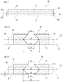
- Fig. 1 is a sectional view of an alkaline water electrolysis diaphragm 90 according to one embodiment of the present invention.
- Fig. 2 is a schematic sectional view showing a distribution of average pore diameters of a porous membrane 91 of the alkaline water electrolysis diaphragm 90 and a positional relation between the porous membrane 91 and a supporting body 92.
- the diaphragm 90 includes: the sheet-shaped porous supporting body 92; and the polymer porous membrane 91 containing organic polymer resin.
- the porous membrane 91 is larger in thickness than the supporting body 92, i.e., the supporting body 92 is thinner than the porous membrane 91.
- the porous membrane 91 is impregnated in the supporting body 92 from one of surfaces of the supporting body 92 to the other surface, i.e., over the whole area in a thickness direction of the supporting body 92.
- the above term "impregnated” denotes that the porous membrane 91 gets into gaps of tissues or structures of the supporting body 92.
- a region of the porous membrane 91 which is impregnated in the supporting body 92 is referred to as an "impregnated region 93.”
- the porous membrane 91 and the supporting body 92 are combined with each other by the impregnated region 93.
- One of membrane surfaces of the porous membrane 91 of the diaphragm 90 i.e., a membrane surface located at an upper side in Figs. 1 and 2
- the other membrane surface of the porous membrane 91 i.e., a membrane surface located at a lower side in Figs. 1 and 2
- a surface B one of membrane surfaces of the porous membrane 91
- one of surfaces of the supporting body 92 is defined as a surface ⁇
- the other surface of the supporting body 92 opposite to the surface ⁇ is defined as a surface ⁇ .
- the surface ⁇ of the supporting body 92 and the surface B of the porous membrane 91 are substantially in flush with each other.
- the above expression “substantially in flush with each other” denotes that: the surface ⁇ of the supporting body 92 and the surface B of the porous membrane 91 are in flush with each other; or the surface ⁇ of the supporting body 92 is located on a flat surface which is parallel to the surface B and is included within a predetermined range from the surface B of the porous membrane 91 in the thickness direction.
- the above expression "the surface ⁇ of the supporting body 92 and the surface B of the porous membrane 91 are substantially in flush with each other” may denote that as shown in Fig. 3 , the surface ⁇ of the supporting body 92 is located on a flat surface which is parallel to the surface B and is included within a range from the surface B of the porous membrane 91 to a position where the surface ⁇ of the supporting body 92 is retreated from the surface B of the porous membrane 91 in the thickness direction (in Fig. 3 , toward an upper side) by ⁇ t1.
- the surface B of the porous membrane 91 is located beyond the surface ⁇ of the supporting body 92 in the thickness direction, and the porous membrane 91 that is denser than the supporting body 92 is exposed on both surfaces of the diaphragm 90. With this, bubbles generated by electrolysis are hardly attached to the surfaces of the diaphragm 90, and therefore, suppression of deterioration of the electrolysis efficiency is expected.
- the average pore diameters are substantially constant in a range extending from the surface A or B of the porous membrane 91 by several micrometers; and the average pore diameters are adequately small in a predetermined range extending from the surface A or B of the porous membrane 91.
- a range located in the vicinity of the surface of the porous membrane 91 and having substantially the same average pore diameter as the surface of the porous membrane 91 is a range extending from the surface of the porous membrane 91 by several to ten-odd micrometers (about 5% of the thickness of the membrane), although such range varies depending on the manufacturing method and material of the porous membrane 91.
- the above ⁇ t1 may be a value that is not more than about 5% of a thickness-direction size of the porous membrane 91.
- the above expression "the surface ⁇ of the supporting body 92 and the surface B of the porous membrane 91 are substantially in flush with each other” may denote that as shown in Fig. 4 , the surface ⁇ of the supporting body 92 is located on a flat surface which is parallel to the surface B and is included within a range from the surface B of the porous membrane 91 to a position where the surface ⁇ of the supporting body 92 is advanced from the surface B of the porous membrane 91 in the thickness direction (in Fig. 4 , toward a lower side) by ⁇ t2.
- Meshes of the supporting body 92 are extremely larger than an average bubble diameter on the surface of the porous membrane 91. Therefore, even when the surface B of the porous membrane 91 is retreated from the surface ⁇ of the supporting body 92 in the thickness direction, both the surface B of the porous membrane 91 and the surface ⁇ of the supporting body 92 appear on the surface of the diaphragm 90 in some cases.
- One example of such cases is the diaphragm 90 in which the surface B of the porous membrane 91 is retreated from the surface ⁇ of the supporting body 92 in the thickness direction by a fiber diameter (diameter) of the supporting body 92.
- the above ⁇ t2 may be a value that is not more than the fiber diameter (diameter) of the supporting body 92.
- the porous membrane 91 appears on one of surfaces of the diaphragm 90 shown in Fig. 4 , and the supporting body 92 and the porous membrane 91 appear on the other surface of the diaphragm 90.
- a thickness-direction middle 92c of the supporting body 92 and a thickness-direction middle 91c of the porous membrane 91 do not coincide with each other, and the thickness-direction middle 92c of the supporting body 92 is located closer to the surface B than the thickness-direction middle 91c of the porous membrane 91.
- the mechanical strength of the porous membrane 91 with respect to friction is low.
- the mechanical strength of the diaphragm 90 is secured since the porous membrane 91 is impregnated in the supporting body 92 to be supported by the supporting body 92.
- the mechanical strength of the diaphragm 90 increases as the thickness of the impregnated region 93 increases.
- the ion permeability of the diaphragm 90 tends to decrease as the thickness of the supporting body 92 increases.
- the mechanical strength and ion permeability of the diaphragm 90 are balanced in such a manner that: the supporting body 92 is formed to be smaller in thickness than the porous membrane 91; and the porous membrane 91 is impregnated in the supporting body 92 over the whole area in the thickness direction such that one of the membrane surfaces of the porous membrane 91 and one of the surfaces of the supporting body 92 are substantially in flush with each other.
- the pore diameter of the porous membrane 91 is evaluated with a scanning electron microscope (SEM).
- SEM scanning electron microscope
- the magnification of the SEM is adjusted such that pores, the number of which is 100 or more and 150 or less, existing on an observation target surface are displayed on a measurement image screen.
- An average length of a maximum length and minimum length of each of the displayed pores is calculated as an arithmetic mean.
- an arithmetic mean of the average lengths of the pores is further calculated as an average pore diameter.
- the observation by the SEM is performed such that the SEM is arranged perpendicular to the observation surface of the membrane.
- the pore is defined as a pore that is surrounded by resin without any break. Further, a pore which is partially located outside the measurement image screen is not regarded as the pore.
- a section parallel to the surfaces A and B of the porous membrane 91 is defined as a section C, and the average pore diameter on the surface A is defined as D A .
- the average pore diameter on the surface B is defined as D B
- the average pore diameter on the section C is defined as D C .
- the average pore diameters D A and D B are substantially equal to each other, and the average pore diameter D C is larger than each of the average pore diameters D A and D B .
- the average pore diameters D A and D B are substantially equal to each other" denotes that a ratio of the average pore diameter D B to the average pore diameter D A (i.e., average pore diameter D B /average pore diameter D A ) is 0.9 to 1.1.
- the average pore diameters of the porous membrane 91 are not uniform in the thickness direction.
- the average pore diameter of the thickness-direction intermediate portion located between the surfaces A and B is larger than the average pore diameter of the membrane surface (each of the surfaces A and B). More specifically, regarding the distribution of the pore diameters of the porous membrane 91, the average pore diameters increase from the surface A toward the thickness-direction intermediate portion, and the average pore diameters increase from the surface B toward the thickness-direction intermediate portion.
- a section having the largest average pore diameter among sections parallel to the surfaces A and B of the porous membrane 91 is not necessarily located at the thickness-direction middle 91c of the porous membrane 91. Further, the increase rate of the average pore diameters from the surface A or B toward the thickness-direction intermediate portion is not necessarily constant.
- the required gas barrier property of the diaphragm 90 can be expressed when at least a part of the porous membrane 91 in the thickness direction includes a section or surface having the pore diameter smaller than a lower limit (i.e., 2 ⁇ m) of the bubble diameter distribution of the electrode generated gas. Then, by increasing the pore diameters of the other part of the porous membrane 91, the ion permeability of the diaphragm 90 can be improved.
- the surface S having the average pore diameter D S is included in the impregnated region 93, the average pore diameter D S being not less than the average pore diameter D A or D B and being smaller than the lower limit of the bubble diameter distribution of the bubbles generated in an alkaline water electrolyzer. If the average pore diameter D S is excessively small (for example, less than 0.01 ⁇ m), the structure of the porous membrane 91 becomes excessively dense, and the ion permeability may deteriorate. Based on this, it is desirable that the average pore diameter D S on the surface S be a value selected from a range of 0.01 to 2 ⁇ m.
- the average pore diameters on the surfaces A and B, the sections close to the surface A, and the sections close to the surface B are smaller than the average pore diameters of the other portion of the porous membrane 91.
- each of the sections close to the surface A and the sections close to the surface B denotes a section that is parallel to the surfaces A and B, is adequately close to the surface A or B, and has the average pore diameter substantially equal to the average pore diameter of each of the surfaces A and B.
- each of both the average pore diameters D A and D B is adequately smaller than the lower limit of the bubble diameter distribution of the electrode generated gas, and the surface B of the porous membrane 91 is included in the impregnated region 93. Therefore, the surface B of the porous membrane 91 satisfies the requirements of the surface S.
- the mechanical strength of the impregnated region 93 of the porous membrane 91 with respect to friction is higher than that of the other portion of the porous membrane 91. Therefore, the pores in the impregnated region 93 are hardly damaged and hardly deform.
- the diaphragm 90 can secure the gas barrier property by which the bubbles generated by the electrolysis cannot penetrate the diaphragm 90.
- a section of the porous membrane 91 parallel to the surfaces A and B is defined as a section L, and the average pore diameter on the section L is defined as a largest average pore diameter D L of the porous membrane 91.
- the section L is included between the surfaces A and B in the thickness direction and is included in the impregnated region 93. Therefore, even if a mechanical load is applied to the diaphragm 90, the largest average pore diameter D L of the porous membrane 91 is maintained.
- the diaphragm 90 can secure high ion permeability in the alkaline water electrolysis.
- the porous membrane 91 of the diaphragm 90 contains organic polymer resin.
- the organic polymer resin is at least one selected from the group consisting of polysulfone, polyether sulfone, polyphenyl sulfone, polyvinylidene fluoride, polycarbonate, polytetrafluoroethylene, polypropylene, polyphenylene sulfide, polyketone, polyether ether ketone, polyimide, and polyether imide.
- Polysulfone, polyether sulfone, polyphenyl sulfone, polyvinylidene fluoride, polycarbonate, polytetrafluoroethylene, polypropylene, polyphenylene sulfide, polyketone, polyether ether ketone, polyimide, and polyether imide are preferable since these adequately have chemical strength (heat resistance and alkali resistance) required for the alkaline water electrolysis diaphragm 90, and the gas barrier property and ion permeability required for the alkaline water electrolysis diaphragm 90 may be realized.
- the porous membrane 91 may further contain a hydrophilic inorganic material selected from titanium oxide (TiO 2 ), zirconium oxide (ZrO 2 ), and a mixture of titanium oxide (TiO 2 ) and zirconium oxide (ZrO 2 ).
- a hydrophilic inorganic material selected from titanium oxide (TiO 2 ), zirconium oxide (ZrO 2 ), and a mixture of titanium oxide (TiO 2 ) and zirconium oxide (ZrO 2 ).
- the thickness of the porous membrane 91 is not especially limited but is preferably 80 to 600 ⁇ m and more preferably 150 to 350 ⁇ m. When the thickness of the porous membrane 91 is 80 ⁇ m or more, the adequate gas barrier property is obtained, and the porous membrane 91 does not break by small impact, and therefore, the supporting body 92 is not exposed. When the thickness of the porous membrane 91 is 600 ⁇ m or less, the permeability of the ions is not inhibited by resistance of the solution contained in the pores, and excellent ion permeability can be achieved.
- porosity of the porous membrane 91 be not less than 80% and not more than 90%.
- the diaphragm 90 can obtain excellent ion permeability. If the porosity of the porous membrane 91 exceeds 90%, the mechanical strength of the porous membrane 91 with respect to friction may significantly deteriorate.
- Weight of Dry Membrane denotes the weight of only the porous membrane 91, and the supporting body 92 is not included.
- Weight of Material Corresponding to Volume of Membrane denotes the weight of the material corresponding to the volume of only the porous membrane 91, and the supporting body 92 is not included.
- the porosity of the porous membrane 91 satisfies the above condition, the improvement of the ion permeability is expected.
- the porosity of the porous membrane 91 is much larger than that of an existing alkaline water electrolysis diaphragm.
- the mechanical strength of the diaphragm 90 is secured since the porous membrane 91 is supported by the supporting body 92.
- the supporting body 92 of the diaphragm 90 is nonwoven fabric, woven fabric, or composite fabric of nonwoven fabric and woven fabric, each of which is formed by fiber of at least one selected from the group consisting of polyphenylene sulfide, polypropylene, polysulfone, polyether sulfone, polyphenyl sulfone, fluorine-based resin, polyketone, polyimide, and polyether imide.
- the composite fabric may be such that woven fabric is included in nonwoven fabric.
- each of polyphenylene sulfide, polypropylene, polysulfone, polyether sulfone, polyphenyl sulfone, fluorine-based resin, polyketone, polyimide, and polyether imide is high in mechanical strength and has the insulation property, the heat resistance, and the alkali resistance. Therefore, the nonwoven fabric, the woven fabric, and the composite fabric, each formed by the fiber of at least one selected from the above group adequately have the mechanical strength and chemical strength required for the diaphragm 90 of the alkaline water electrolytic apparatus. Thus, these are preferable as the material of the supporting body 92. By using the supporting body 92 made of the above material, easiness of manufacture of the diaphragm 90 can be improved.
- a fiber basis weight (the weight of the fiber per unit area; g/m 2 ) of the supporting body 92 is preferably 20 to 200 g/m 2 and more preferably 40 to 100 g/m 2 .
- the diaphragm 90 including the supporting body 92 having the fiber basis weight of less than 20 g/m 2 cannot obtain excellent gas barrier property. Further, the diaphragm 90 including the supporting body 92 having the fiber basis weight of more than 200 g/m 2 may cause inadequate electrolysis efficiency and membrane formation failure.
- the alkaline water electrolysis diaphragm 90 is manufactured in such a manner that the porous membrane 91 containing the organic polymer resin is formed at the supporting body 92 by a phase separation method.
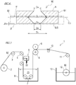
- Fig. 5 is a diagram showing a schematic configuration of the manufacturing apparatus 1 for the alkaline water electrolysis diaphragm 90.
- the manufacturing apparatus 1 can continuously manufacture the diaphragm 90.
- the manufacturing apparatus 1 shown in Fig. 5 includes: a coating unit 5; a chemical liquid tank 6; an unwinding drum 2 that is a web roll of the supporting body 92; a winding drum 12 configured to wind the diaphragm 90 (product); and a water tank 13 in which the winding drum 12 is immersed in water for maintaining a wet state of the diaphragm 90.
- the manufacturing apparatus 1 further includes: a plurality of guide rollers 3, 4, 7, and 11 that form a transfer pathway for the supporting body 92 and the product, the transfer pathway extending from the unwinding drum 2 through the coating unit 5 and the chemical liquid tank 6 to the winding drum 12; a driving roller 8 and nip roller 9 configured to transfer the diaphragm 90 along the transfer pathway; and a slitter 10 configured to cut the transferred diaphragm 90 into a desired size.
- the coating unit 5 includes a slit through which a membrane forming solution 22 flows out.
- the coating unit 5 applies the membrane forming solution 22 to the surface of the moving supporting body 92 at a predetermined thickness.
- the coating unit 5 can apply the membrane forming solution 22 to one selected surface of the supporting body 92. Further, the coating unit 5 can adjust the degree of impregnation of the membrane forming solution 22 in the supporting body 92 (i.e., the depth of impregnation of the membrane forming solution 22 from the surface of the supporting body 92 in the thickness direction).
- the membrane forming solution 22 is supplied to the coating unit 5 from a solution supply device (not shown).
- the membrane forming solution 22 is prepared in the solution supply device in such a manner that organic polymer resin in powder form and an additive that acts on structures (pore diameter, pore distribution, etc.) of the porous membrane 91 are dissolved in an organic solvent.
- the organic solvent of the membrane forming solution 22 needs to be an organic solvent in which the organic polymer resin contained in the porous membrane 91 can be dissolved and which has miscibility with water.
- organic solvent is at least one selected from the group consisting of dimethyl sulfoxide (DMSO), N-methyl-2-pyrrolidone (NMP), dimethylformamide (DMF), dimethylacetamide (DMAc), and a mixture of these.
- the membrane forming solution 22 is prepared in advance by adding the organic polymer resin to the organic solvent.
- the supporting body 92 is unwound from the unwinding drum 2 to move along the transfer pathway through the coating unit 5, the chemical liquid tank 6, the slitter 10, and the water tank 13 in this order.
- the membrane forming solution 22 is applied to one of the surfaces of the supporting body 92.
- the membrane forming solution 22 is applied to the supporting body 92 so as to be impregnated in the supporting body 92 from one of the surfaces to the other surface.
- the membrane forming solution 22 may be applied to the supporting body 92 such that the membrane forming solution 22 applied to one of the surfaces of the supporting body 92 slightly exudes from the other surface.
- coatings of the membrane forming solution 22 are formed on both surfaces of the supporting body 92. It should be noted that the thickness of the diaphragm 90 as the product is adjusted by the thickness of the membrane forming solution 22 applied to the supporting body 92.
- the supporting body 92 to which the membrane forming solution 22 is applied is immersed in a chemical liquid 23.
- the chemical liquid 23 may be water.
- Both surfaces of the membrane forming solution 22 applied to the supporting body 92 are exposed to water under substantially the same condition.
- both surfaces of the membrane forming solution 22 applied to the supporting body 92 can be exposed to water under substantially the same condition in such a manner that the supporting body 92 is put into the chemical liquid 23 so as to be perpendicular to the surface of the chemical liquid 23.
- phase separation of the polymer resin and the solvent occurs.
- the polymer resin in the phase separation state solidifies, a porous structure (i.e., the porous membrane 91) is formed.
- the supporting body 92 to which the membrane forming solution 22 is applied is immersed in the chemical liquid 23.
- the membrane forming solution 22 applied to the supporting body 92 may be caused to contact humidified air (or water).
- the supporting body 92 on which the porous membrane 91 is formed as above is then sandwiched between the driving roller 8 and the nip roller 9.
- the thickness of the supporting body 92 is uniformized, and excess water is removed from the supporting body 92.
- the supporting body 92 is cut by the slitter 10 into an appropriate size and wound by the winding drum 12.
- the porous membrane 91 since the porous membrane 91 is moved while being supported by the supporting body 92, the porous membrane 91 hardly breaks and stretches during manufacturing. Therefore, severe adjustment of a movement speed of the supporting body 92 in the manufacturing apparatus 1 is not required, and a manufacturing speed can be made higher than a conventional manufacturing speed. Further, by using a wide web roll of the supporting body 92, a diaphragm (a square shape having 2,000 mm on each side) larger than a conventionally used diaphragm can be manufactured.
- the pore diameters of the diaphragm samples were evaluated with a scanning electron microscope (SEM; field emission type scanning electron microscope JSF-7000F produced by JEOL Ltd.). First, each sample was cut to have a predetermined size and was then subjected to metal coating by a magnetron sputtering device (auto fine coater JEC-3000FC produced by JEOL Ltd.). Next, the sample was set on an observation sample table of the SEM, and measurement was started. At this time, the sample was set such that the SEM could observe the membrane from a direction perpendicular to the membrane.
- SEM scanning electron microscope
- the magnification of the SEM was adjusted such that pores, the number of which was 100 or more and 150 or less, existing on a porous membrane surface that is an observation target were displayed on a measurement image screen.
- An average length of a maximum length and minimum length of each of the displayed pores was calculated as an arithmetic mean.
- an arithmetic mean D of the average lengths of the pores was further calculated as an average pore diameter of the target membrane.
- the pore in this evaluation is defined as a pore that is surrounded by resin without any break. Further, a pore which is partially located outside the measurement image screen is not regarded as the pore.
- section C of the porous membrane 91 freeze-fracture was performed in a direction parallel to the surface A at a position located between the surfaces A and B and away from the surface A by 200 ⁇ m in the thickness direction. This section was observed in the same manner as the above surface
- the testing apparatus 50 includes an electrolysis cell 30, an electrolytic solution storage tank 51, a DC power supply device 65, a computer 66, and the like.
- a KOH aqueous solution that is an electrolytic solution is produced and stored in the electrolytic solution storage tank 51.
- the electrolytic solution is supplied from the electrolytic solution storage tank 51 through a pipe 55 to an anode chamber 48 of the electrolysis cell 30.
- the electrolytic solution is supplied from the electrolytic solution storage tank 51 through a pipe 58 to a cathode chamber 49 of the electrolysis cell 30.
- a predetermined DC current flows from the DC power supply device 65 to each electrode of the electrolysis cell 30.
- the testing apparatus 50 includes: a voltmeter configured to measure a voltage between the anode and cathode of the electrolysis cell 30; and an overvoltage measuring device configured to measure an oxygen overvoltage and a hydrogen overvoltage. Measurement results of the voltmeter and the overvoltage measuring device are analyzed by the computer 66.
- Oxygen is generated by water electrolysis in the anode chamber 48 of the electrolysis cell 30, and the KOH aqueous solution and the oxygen are discharged from the anode chamber 48 through a pipe 61.
- Hydrogen is generated by water electrolysis in the cathode chamber 49 of the electrolysis cell 30, and the KOH aqueous solution and the hydrogen are discharged from the cathode chamber 49 through a pipe 62.
- the oxygen concentration of the discharged hydrogen and the hydrogen concentration of the discharged oxygen are measured with a gas chromatograph analyzer (not shown; GC-14B produced by Shimadzu Corporation).
- the electrolytic solution (KOH aqueous solution) supplied from the electrolytic solution storage tank 51 to the electrolysis cell 30 had a concentration of 25 wt.% and a temperature of 80°C.
- a pure nickel mesh was used as the anode 31a, and an active cathode for hydrogen generation was used as the cathode 32a.
- An electrolysis area of the electrolysis cell 30 was 1 dm 2 .
- the electrolysis voltage, the hydrogen concentration in the generated oxygen, the oxygen concentration in the generated hydrogen, the oxygen overvoltage, and the hydrogen overvoltage, which were necessary for causing a cell current of 0.4 A/cm 2 to flow from the power supply device 65 to the electrolysis cell 30, were measured with the testing apparatus 50 having the above configuration.
- a membrane forming solution shown below was prepared by stirring polysulfone (Udel P (trademark) produced by Solvay Advanced Polymers LLC), polyethylene oxide (average Mv of 100,000; produced by Sigma-Aldrich Japan), and N-methyl-2-pyrrolidone (produced by Tokyo Chemical Industry Co., Ltd.) at a temperature of 70°C.
- polysulfone Udel P (trademark) produced by Solvay Advanced Polymers LLC
- polyethylene oxide average Mv of 100,000; produced by Sigma-Aldrich Japan
- N-methyl-2-pyrrolidone produced by Tokyo Chemical Industry Co., Ltd.
- the membrane forming solution was applied to PPS nonwoven fabric (Torcon paper (trademark) produced by Toray Industries, Inc.) that is the supporting body so as to have a total membrane thickness of about 300 ⁇ m.
- PPS nonwoven fabric Tecon paper (trademark) produced by Toray Industries, Inc.
- the supporting body was immersed in pure water of 40°C in a chemical liquid tank (solidifying bath) so as to be perpendicular to the surface of the water.
- the phase separation and solidification of the organic polymer resin were performed.
- the supporting body was washed well with pure water for removing the organic solvent.
- the diaphragm sample according to Example 1 was prepared.
- the diaphragm sample according to Comparative Example 1 was prepared in the same manner as Example 1 except that: after the membrane forming solution was applied to the supporting body, a fluorocarbon resin sheet (NITOFLON (trademark) No.900UL produced by Nitto Denko Corporation; Width of 300 mm, Thickness of 0.1 mm) was attached to one surface of the supporting body; and immediately after that, the supporting body was immersed in pure water of 40°C in a chemical liquid tank so as to be perpendicular to the surface of the water, and thus, the phase separation and solidification of the organic polymer resin were performed.
- a fluorocarbon resin sheet (NITOFLON (trademark) No.900UL produced by Nitto Denko Corporation; Width of 300 mm, Thickness of 0.1 mm) was attached to one surface of the supporting body; and immediately after that, the supporting body was immersed in pure water of 40°C in a chemical liquid tank so as to be perpendicular to the surface of the water, and thus, the
- a membrane forming solution shown below was prepared by stirring polyether sulfone (Udel E (trademark) produced by Solvay Advanced Polymers LLC), polyethylene oxide (average Mv of 100,000; produced by Sigma-Aldorich Japan), and N-methyl-2-pyrrolidone (produced by Tokyo Chemical Industry Co., Ltd.) at a temperature of 70°C.
- polyether sulfone Udel E (trademark) produced by Solvay Advanced Polymers LLC
- polyethylene oxide average Mv of 100,000; produced by Sigma-Aldorich Japan
- N-methyl-2-pyrrolidone produced by Tokyo Chemical Industry Co., Ltd.
- the membrane forming solution was applied to PPS nonwoven fabric (Torcon paper (trademark) produced by Toray Industries, Inc.) that is the supporting body so as to have a total membrane thickness of about 300 ⁇ m.
- PPS nonwoven fabric Tecon paper (trademark) produced by Toray Industries, Inc.
- the supporting body was immersed in pure water of 40°C in a chemical liquid tank (solidifying bath) so as to be perpendicular to the surface of the water.
- the phase separation and solidification of the organic polymer resin were performed.
- the supporting body was washed well with pure water for removing the organic solvent.
- the diaphragm sample according to Example 1 was prepared.
- the diaphragm sample according to Comparative Example 1 was prepared in the same manner as Example 1 except that: after the membrane forming solution was applied to the supporting body, a fluorocarbon resin sheet (NITOFLON (trademark) No.900UL produced by Nitto Denko Corporation; Width of 300 mm, Thickness of 0.1 mm) was attached to one surface of the supporting body; and immediately after that, the supporting body was immersed in pure water of 40°C in a chemical liquid tank so as to be perpendicular to the surface of the water, and thus, the phase separation and solidification of the organic polymer resin were performed.
- a fluorocarbon resin sheet (NITOFLON (trademark) No.900UL produced by Nitto Denko Corporation; Width of 300 mm, Thickness of 0.1 mm) was attached to one surface of the supporting body; and immediately after that, the supporting body was immersed in pure water of 40°C in a chemical liquid tank so as to be perpendicular to the surface of the water, and thus, the
- Table 1 shows results of the evaluations of the pore diameters and properties of the diaphragm samples according to Example 1 and Comparative Example 1.
- the average pore diameters on the surfaces A and B of the porous membrane are substantially equal to each other, and the average pore diameter on the section located between the surfaces A and B in the thickness direction and parallel to the surfaces A and B is larger than each of the average pore diameters on the surfaces A and B.
- the average pore diameter on the surface A of the porous membrane is significantly larger than the average pore diameter on the surface B of the porous membrane.
- the measurement result of the electrolysis voltage of the diaphragm sample according to Example 1 was more excellent than that of the diaphragm sample according to Comparative Example 1. With this, it can be guessed that since the amount of bubbles attached to the surface of the diaphragm sample according to Example 1 is made smaller than that of the diaphragm sample according to Comparative Example 1, an increase in the electrolysis voltage in Example 1 is suppressed.
Landscapes
- Chemical & Material Sciences (AREA)
- Engineering & Computer Science (AREA)
- Chemical Kinetics & Catalysis (AREA)
- Electrochemistry (AREA)
- Materials Engineering (AREA)
- Metallurgy (AREA)
- Organic Chemistry (AREA)
- Inorganic Chemistry (AREA)
- Electrolytic Production Of Non-Metals, Compounds, Apparatuses Therefor (AREA)
- Separation Using Semi-Permeable Membranes (AREA)
Applications Claiming Priority (2)
| Application Number | Priority Date | Filing Date | Title |
|---|---|---|---|
| JP2015121129A JP6905308B2 (ja) | 2015-06-16 | 2015-06-16 | アルカリ水電解用隔膜及びその製造方法 |
| PCT/JP2016/002378 WO2016203701A1 (fr) | 2015-06-16 | 2016-05-16 | Diaphragme pour l'électrolyse d'eau alcaline et procédé pour la fabrication de ce dernier |
Publications (3)
| Publication Number | Publication Date |
|---|---|
| EP3312306A1 true EP3312306A1 (fr) | 2018-04-25 |
| EP3312306A4 EP3312306A4 (fr) | 2019-02-27 |
| EP3312306B1 EP3312306B1 (fr) | 2020-08-12 |
Family
ID=57545719
Family Applications (1)
| Application Number | Title | Priority Date | Filing Date |
|---|---|---|---|
| EP16811182.1A Active EP3312306B1 (fr) | 2015-06-16 | 2016-05-16 | Diaphragme pour l'électrolyse d'eau alcaline et procédé pour la fabrication de ce dernier |
Country Status (6)
| Country | Link |
|---|---|
| US (1) | US10914014B2 (fr) |
| EP (1) | EP3312306B1 (fr) |
| JP (1) | JP6905308B2 (fr) |
| CN (2) | CN107709622B (fr) |
| CA (1) | CA2989389C (fr) |
| WO (1) | WO2016203701A1 (fr) |
Cited By (14)
| Publication number | Priority date | Publication date | Assignee | Title |
|---|---|---|---|---|
| EP3933069A1 (fr) * | 2020-07-03 | 2022-01-05 | Agfa-Gevaert Nv | Séparateur pour l'électrolyse de l'eau alcaline |
| WO2022056606A1 (fr) * | 2020-09-21 | 2022-03-24 | University Of Wollongong | Procédé de fonctionnement de cellules électro-synthétiques ou électro-énergétiques à base capillaire |
| WO2023280600A1 (fr) | 2021-07-08 | 2023-01-12 | Agfa-Gevaert Nv | Séparateur pour électrolyse d'une solution aqueuse alcaline |
| WO2023280760A1 (fr) | 2021-07-08 | 2023-01-12 | Agfa-Gevaert Nv | Séparateur pour l'électrolyse alcaline d'eau |
| WO2023280598A1 (fr) | 2021-07-08 | 2023-01-12 | Agfa-Gevaert Nv | Séparateur pour électrolyse d'une solution aqueuse alcaline |
| WO2023118088A1 (fr) | 2021-12-21 | 2023-06-29 | Agfa-Gevaert Nv | Séparateur pour cellule électrolytique |
| WO2023208776A1 (fr) | 2022-04-25 | 2023-11-02 | Agfa-Gevaert Nv | Séparateur pour électrolyse d'eau alcaline |
| WO2023232551A1 (fr) | 2022-05-30 | 2023-12-07 | Agfa-Gevaert Nv | Séparateur pour l' électrolyse de l'eau |
| EP4365335A1 (fr) | 2022-11-03 | 2024-05-08 | Agfa-Gevaert Nv | Séparateur pour électrolyse d'eau alcaline |
| EP4365334A1 (fr) | 2022-11-03 | 2024-05-08 | Agfa-Gevaert Nv | Séparateur pour électrolyse d'eau alcaline |
| WO2025132855A1 (fr) | 2023-12-21 | 2025-06-26 | Agfa-Gevaert Nv | Séparateur pour électrolyse d'eau alkaline |
| WO2025132806A1 (fr) | 2023-12-21 | 2025-06-26 | Agfa-Gevaert Nv | Séparateur pour électrolyse d'eau alcaline |
| EP4407072A4 (fr) * | 2021-09-24 | 2025-08-27 | Nippon Catalytic Chem Ind | Procédé de production d'un diaphragme d'utilisation d'électrolyse d'eau alcaline, et diaphragme d'utilisation d'électrolyse d'eau alcaline |
| EP4671415A1 (fr) | 2024-06-28 | 2025-12-31 | Agfa-Gevaert Nv | Séparateur pour électrolyse d'eau |
Families Citing this family (20)
| Publication number | Priority date | Publication date | Assignee | Title |
|---|---|---|---|---|
| EP4219794B1 (fr) | 2017-03-22 | 2025-05-07 | Asahi Kasei Kabushiki Kaisha | Procédé de fabrication d'un nouvel électrolyseur |
| CN110869538B (zh) * | 2017-07-10 | 2022-02-11 | 爱克发-格法特公司 | 用于碱解的强化隔膜 |
| CN110945161A (zh) * | 2017-07-26 | 2020-03-31 | 株式会社日本触媒 | 碱水电解用隔膜、其制造方法以及无机有机复合膜的制造方法 |
| JP2019056136A (ja) * | 2017-09-20 | 2019-04-11 | 株式会社東芝 | 電気化学反応装置 |
| JP7273929B2 (ja) * | 2017-09-20 | 2023-05-15 | 株式会社東芝 | 電気化学反応装置および多孔質セパレータ |
| JP6802827B2 (ja) * | 2018-09-18 | 2020-12-23 | 株式会社東芝 | 水素製造装置及び隔膜 |
| WO2020059623A1 (fr) | 2018-09-21 | 2020-03-26 | 旭化成株式会社 | Procédé de fabrication de cellule électrolytique, stratifiée, cellule électrolytique stratifiée et procédé de fonctionnement de cellule électrolytique |
| CN112739853B (zh) | 2018-09-21 | 2024-06-18 | 旭化成株式会社 | 层积体制造用夹具、层积体的制造方法、包装体、层积体、电解槽以及电解槽的制造方法 |
| US20220025530A1 (en) | 2018-09-21 | 2022-01-27 | Asahi Kasei Kabushiki Kaisha | Electrode for electrolysis and laminate |
| CN112639169B (zh) | 2018-09-21 | 2023-12-01 | 旭化成株式会社 | 层积体、层积体的保存方法、层积体的输送方法、保护层积体及其卷绕体 |
| JP7166118B2 (ja) * | 2018-09-26 | 2022-11-07 | 株式会社日本触媒 | アルカリ水電解用隔膜 |
| JP7114726B2 (ja) * | 2018-09-26 | 2022-08-08 | 株式会社日本触媒 | アルカリ水電解用隔膜 |
| EP3879006A4 (fr) * | 2018-11-05 | 2021-12-29 | Asahi Kasei Kabushiki Kaisha | Procédé de fabrication d'hydrogène |
| WO2021172508A1 (fr) | 2020-02-26 | 2021-09-02 | 旭化成株式会社 | Réservoir électrolytique et procédé de fabrication de réservoir électrolytique |
| JP7413304B2 (ja) * | 2021-03-18 | 2024-01-15 | 株式会社東芝 | 二酸化炭素電解装置 |
| CN115029732B (zh) * | 2022-06-06 | 2024-04-19 | 清华大学 | 碱性水电解用隔膜及其制备方法与应用 |
| US20240068116A1 (en) * | 2022-08-31 | 2024-02-29 | Uop Llc | Microporous asymmetric organic/inorganic composite membrane |
| EP4582595A1 (fr) | 2022-09-01 | 2025-07-09 | Nippon Shokubai Co., Ltd. | Diaphragme pour électrolyse d'eau alcaline, cellule d'électrolyse d'eau alcaline et procédé d'électrolyse d'eau alcaline |
| CN115928145B (zh) | 2022-12-28 | 2023-10-13 | 嘉庚创新实验室 | 一种碱性电解水制氢用有机-无机复合隔膜及其制备方法 |
| CN116200779B (zh) * | 2023-01-19 | 2025-10-17 | 清华大学 | 碱性水电解用复合隔膜及其制备方法和应用 |
Family Cites Families (23)
| Publication number | Priority date | Publication date | Assignee | Title |
|---|---|---|---|---|
| JPS62280231A (ja) * | 1986-05-30 | 1987-12-05 | Asahi Glass Co Ltd | 新規な複層隔膜 |
| JPS6393309A (ja) * | 1986-10-08 | 1988-04-23 | Fuji Photo Film Co Ltd | 微孔性膜の処理法 |
| JPH03245456A (ja) * | 1990-02-21 | 1991-11-01 | Asahi Chem Ind Co Ltd | 非水電解液電池のセパレータ用微多孔膜 |
| JP3681219B2 (ja) * | 1996-05-23 | 2005-08-10 | 日東電工株式会社 | ポリスルホン多孔質分離膜 |
| US6666969B1 (en) * | 1998-10-01 | 2003-12-23 | Tonen Chemical Corporation | Microporous polyolefin film and process for producing the same |
| JP4588286B2 (ja) | 2001-09-28 | 2010-11-24 | 帝人株式会社 | 複合多孔膜の製造法 |
| US8962132B2 (en) * | 2004-09-28 | 2015-02-24 | Giner, Inc. | Solid polymer electrolyte composite membrane comprising a porous support and a solid polymer electrolyte including a dispersed reduced noble metal or noble metal oxide |
| JP4998713B2 (ja) | 2006-11-16 | 2012-08-15 | 栗田工業株式会社 | イオン透過性隔膜 |
| JP2009185333A (ja) | 2008-02-06 | 2009-08-20 | Kurita Water Ind Ltd | イオン透過性隔膜の製造方法 |
| WO2009147086A1 (fr) | 2008-06-02 | 2009-12-10 | Agfa-Gevaert | Appareil et procédé de production d'un séparateur renforcé par une bande perméable aux ions et séparateur pouvant être obtenu avec ces derniers |
| EP2296825B1 (fr) * | 2008-06-02 | 2017-05-10 | Agfa-Gevaert N.V. | Processus de production d'un séparateur perméable aux ions et renforcé par un tissu |
| CN101656306B (zh) * | 2008-08-22 | 2012-07-04 | 比亚迪股份有限公司 | 一种复合隔膜及其制备方法和包括该复合隔膜的电池 |
| JP2010255096A (ja) * | 2009-03-31 | 2010-11-11 | Kurita Water Ind Ltd | イオン透過性隔膜の製造装置及び製造方法 |
| JP2011025110A (ja) * | 2009-07-22 | 2011-02-10 | Toray Ind Inc | 分離膜およびその製造方法 |
| RU2551365C2 (ru) * | 2011-02-28 | 2015-05-20 | Вито Нв | Новый сепаратор, электрохимическая ячейка с новым сепаратором и применение нового сепаратора в электрохимической ячейке |
| ES2606356T3 (es) * | 2011-12-20 | 2017-03-23 | Ingeteam Power Technology, S.A. | Diafragma de speek para electrolisis alcalina y su uso |
| JP5424179B1 (ja) * | 2012-02-15 | 2014-02-26 | 東レバッテリーセパレータフィルム株式会社 | 電池用セパレータ、および、電池用セパレータの製造方法 |
| JP5981751B2 (ja) * | 2012-03-29 | 2016-08-31 | 旭化成株式会社 | アルカリ水電解用隔膜及びその製造方法 |
| KR102036519B1 (ko) * | 2012-03-29 | 2019-10-25 | 도레이 카부시키가이샤 | 전지 세퍼레이터 및 그 제조방법 |
| US10056595B2 (en) * | 2012-04-13 | 2018-08-21 | Toray Industries, Inc. | Battery separator, and method for producing same |
| JP5893511B2 (ja) * | 2012-05-31 | 2016-03-23 | 日東電工株式会社 | アルカリ水電解用隔膜 |
| JP6030952B2 (ja) * | 2012-12-28 | 2016-11-24 | 旭化成株式会社 | アルカリ水電解用隔膜及びその製造方法 |
| JP2015101775A (ja) * | 2013-11-27 | 2015-06-04 | 日東電工株式会社 | アルカリ水電解用隔膜の製造方法 |
-
2015
- 2015-06-16 JP JP2015121129A patent/JP6905308B2/ja active Active
-
2016
- 2016-05-16 CA CA2989389A patent/CA2989389C/fr active Active
- 2016-05-16 US US15/737,451 patent/US10914014B2/en active Active
- 2016-05-16 CN CN201680032936.XA patent/CN107709622B/zh active Active
- 2016-05-16 WO PCT/JP2016/002378 patent/WO2016203701A1/fr not_active Ceased
- 2016-05-16 CN CN202011047515.9A patent/CN112159989B/zh active Active
- 2016-05-16 EP EP16811182.1A patent/EP3312306B1/fr active Active
Cited By (20)
| Publication number | Priority date | Publication date | Assignee | Title |
|---|---|---|---|---|
| AU2021299938B2 (en) * | 2020-07-03 | 2024-05-30 | Agfa-Gevaert Nv | A separator for alkaline water electrolysis |
| WO2022002904A1 (fr) * | 2020-07-03 | 2022-01-06 | Agfa-Gevaert Nv | Séparateur pour l'électrolyse alcaline d'eau |
| EP3933069A1 (fr) * | 2020-07-03 | 2022-01-05 | Agfa-Gevaert Nv | Séparateur pour l'électrolyse de l'eau alcaline |
| WO2022056606A1 (fr) * | 2020-09-21 | 2022-03-24 | University Of Wollongong | Procédé de fonctionnement de cellules électro-synthétiques ou électro-énergétiques à base capillaire |
| WO2022056604A1 (fr) * | 2020-09-21 | 2022-03-24 | University Of Wollongong | Cellules électro-synthétiques d'électrolyse de l'eau fondées sur la capillarité |
| WO2023280600A1 (fr) | 2021-07-08 | 2023-01-12 | Agfa-Gevaert Nv | Séparateur pour électrolyse d'une solution aqueuse alcaline |
| WO2023280760A1 (fr) | 2021-07-08 | 2023-01-12 | Agfa-Gevaert Nv | Séparateur pour l'électrolyse alcaline d'eau |
| WO2023280598A1 (fr) | 2021-07-08 | 2023-01-12 | Agfa-Gevaert Nv | Séparateur pour électrolyse d'une solution aqueuse alcaline |
| EP4407072A4 (fr) * | 2021-09-24 | 2025-08-27 | Nippon Catalytic Chem Ind | Procédé de production d'un diaphragme d'utilisation d'électrolyse d'eau alcaline, et diaphragme d'utilisation d'électrolyse d'eau alcaline |
| WO2023118088A1 (fr) | 2021-12-21 | 2023-06-29 | Agfa-Gevaert Nv | Séparateur pour cellule électrolytique |
| WO2023208776A1 (fr) | 2022-04-25 | 2023-11-02 | Agfa-Gevaert Nv | Séparateur pour électrolyse d'eau alcaline |
| WO2023232551A1 (fr) | 2022-05-30 | 2023-12-07 | Agfa-Gevaert Nv | Séparateur pour l' électrolyse de l'eau |
| EP4365335A1 (fr) | 2022-11-03 | 2024-05-08 | Agfa-Gevaert Nv | Séparateur pour électrolyse d'eau alcaline |
| WO2024094454A2 (fr) | 2022-11-03 | 2024-05-10 | Agfa-Gevaert Nv | Séparateur pour électrolyse d'eau alcaline |
| WO2024094453A2 (fr) | 2022-11-03 | 2024-05-10 | Agfa-Gevaert Nv | Séparateur pour électrolyse d'eau alcaline |
| EP4365334A1 (fr) | 2022-11-03 | 2024-05-08 | Agfa-Gevaert Nv | Séparateur pour électrolyse d'eau alcaline |
| WO2025132855A1 (fr) | 2023-12-21 | 2025-06-26 | Agfa-Gevaert Nv | Séparateur pour électrolyse d'eau alkaline |
| WO2025132806A1 (fr) | 2023-12-21 | 2025-06-26 | Agfa-Gevaert Nv | Séparateur pour électrolyse d'eau alcaline |
| EP4671415A1 (fr) | 2024-06-28 | 2025-12-31 | Agfa-Gevaert Nv | Séparateur pour électrolyse d'eau |
| WO2026003147A1 (fr) | 2024-06-28 | 2026-01-02 | Agfa-Gevaert Nv | Séparateur pour électrolyse de l'eau |
Also Published As
| Publication number | Publication date |
|---|---|
| JP2017002389A (ja) | 2017-01-05 |
| CN107709622B (zh) | 2020-10-27 |
| EP3312306A4 (fr) | 2019-02-27 |
| CN107709622A (zh) | 2018-02-16 |
| US20180171494A1 (en) | 2018-06-21 |
| JP6905308B2 (ja) | 2021-07-21 |
| US10914014B2 (en) | 2021-02-09 |
| EP3312306B1 (fr) | 2020-08-12 |
| CA2989389A1 (fr) | 2016-12-22 |
| CN112159989A (zh) | 2021-01-01 |
| CN112159989B (zh) | 2023-08-22 |
| CA2989389C (fr) | 2021-02-16 |
| WO2016203701A1 (fr) | 2016-12-22 |
Similar Documents
| Publication | Publication Date | Title |
|---|---|---|
| EP3312306B1 (fr) | Diaphragme pour l'électrolyse d'eau alcaline et procédé pour la fabrication de ce dernier | |
| EP2831312B1 (fr) | Assemblage d'un substrat de diffusion de métal poreux et d'une membrane de séparation polymère | |
| CA2934431C (fr) | Diaphragme pour electrolyse d'eau alcaline, son procede de production, et appareil d'electrolyse d'eau alcaline | |
| KR20230019201A (ko) | 알칼리수 전기분해를 위한 세퍼레이터 | |
| EP4625561A2 (fr) | Membranes ionomères hautement renforcées pour une sélectivité élevée et une résistance élevé | |
| US20250171918A1 (en) | A Separator for Alkaline Water Electrolysis | |
| US20250051942A1 (en) | A Separator for an Electrolytic Cell | |
| JP2014129563A (ja) | アルカリ水電解用隔膜及びその製造方法 | |
| JP7783970B2 (ja) | アルカリ水電解用セパレータ | |
| EP4367290A1 (fr) | Séparateur pour électrolyse d'une solution aqueuse alcaline | |
| US20250003091A1 (en) | A Separator for Alkaline Water Electrolysis | |
| JP2019216060A (ja) | ガス拡散電極の微多孔層を形成するための塗液の製造方法 | |
| WO2025263231A1 (fr) | Film poreux, son procédé de production, élément d'électrolyse de l'eau alcaline, cellule d'électrolyse de l'eau alcaline, dispositif d'électrolyse de l'eau alcaline et procédé de production d'hydrogène | |
| WO2025205501A1 (fr) | Séparateur poreux pour électrolyse d'eau alcaline, élément d'électrolyse d'eau alcaline l'utilisant, cellule d'électrolyse d'eau alcaline, dispositif d'électrolyse d'eau alcaline et procédé de production d'hydrogène |
Legal Events
| Date | Code | Title | Description |
|---|---|---|---|
| STAA | Information on the status of an ep patent application or granted ep patent |
Free format text: STATUS: THE INTERNATIONAL PUBLICATION HAS BEEN MADE |
|
| PUAI | Public reference made under article 153(3) epc to a published international application that has entered the european phase |
Free format text: ORIGINAL CODE: 0009012 |
|
| STAA | Information on the status of an ep patent application or granted ep patent |
Free format text: STATUS: REQUEST FOR EXAMINATION WAS MADE |
|
| 17P | Request for examination filed |
Effective date: 20171220 |
|
| AK | Designated contracting states |
Kind code of ref document: A1 Designated state(s): AL AT BE BG CH CY CZ DE DK EE ES FI FR GB GR HR HU IE IS IT LI LT LU LV MC MK MT NL NO PL PT RO RS SE SI SK SM TR |
|
| AX | Request for extension of the european patent |
Extension state: BA ME |
|
| DAV | Request for validation of the european patent (deleted) | ||
| DAX | Request for extension of the european patent (deleted) | ||
| REG | Reference to a national code |
Ref country code: DE Ref legal event code: R079 Ref document number: 602016041961 Country of ref document: DE Free format text: PREVIOUS MAIN CLASS: C25B0013020000 Ipc: C25B0001100000 |
|
| A4 | Supplementary search report drawn up and despatched |
Effective date: 20190130 |
|
| RIC1 | Information provided on ipc code assigned before grant |
Ipc: C25B 1/10 20060101AFI20190124BHEP Ipc: C25B 13/02 20060101ALI20190124BHEP Ipc: C25B 13/08 20060101ALI20190124BHEP |
|
| TPAC | Observations filed by third parties |
Free format text: ORIGINAL CODE: EPIDOSNTIPA |
|
| STAA | Information on the status of an ep patent application or granted ep patent |
Free format text: STATUS: EXAMINATION IS IN PROGRESS |
|
| 17Q | First examination report despatched |
Effective date: 20191018 |
|
| TPAC | Observations filed by third parties |
Free format text: ORIGINAL CODE: EPIDOSNTIPA |
|
| GRAP | Despatch of communication of intention to grant a patent |
Free format text: ORIGINAL CODE: EPIDOSNIGR1 |
|
| STAA | Information on the status of an ep patent application or granted ep patent |
Free format text: STATUS: GRANT OF PATENT IS INTENDED |
|
| INTG | Intention to grant announced |
Effective date: 20200331 |
|
| GRAS | Grant fee paid |
Free format text: ORIGINAL CODE: EPIDOSNIGR3 |
|
| GRAA | (expected) grant |
Free format text: ORIGINAL CODE: 0009210 |
|
| STAA | Information on the status of an ep patent application or granted ep patent |
Free format text: STATUS: THE PATENT HAS BEEN GRANTED |
|
| AK | Designated contracting states |
Kind code of ref document: B1 Designated state(s): AL AT BE BG CH CY CZ DE DK EE ES FI FR GB GR HR HU IE IS IT LI LT LU LV MC MK MT NL NO PL PT RO RS SE SI SK SM TR |
|
| REG | Reference to a national code |
Ref country code: CH Ref legal event code: EP |
|
| REG | Reference to a national code |
Ref country code: IE Ref legal event code: FG4D |
|
| REG | Reference to a national code |
Ref country code: DE Ref legal event code: R096 Ref document number: 602016041961 Country of ref document: DE |
|
| REG | Reference to a national code |
Ref country code: AT Ref legal event code: REF Ref document number: 1301637 Country of ref document: AT Kind code of ref document: T Effective date: 20200915 |
|
| REG | Reference to a national code |
Ref country code: DE Ref legal event code: R079 Ref document number: 602016041961 Country of ref document: DE Free format text: PREVIOUS MAIN CLASS: C25B0001100000 Ipc: C25B0001040000 |
|
| REG | Reference to a national code |
Ref country code: LT Ref legal event code: MG4D |
|
| REG | Reference to a national code |
Ref country code: NL Ref legal event code: MP Effective date: 20200812 |
|
| PG25 | Lapsed in a contracting state [announced via postgrant information from national office to epo] |
Ref country code: FI Free format text: LAPSE BECAUSE OF FAILURE TO SUBMIT A TRANSLATION OF THE DESCRIPTION OR TO PAY THE FEE WITHIN THE PRESCRIBED TIME-LIMIT Effective date: 20200812 Ref country code: NO Free format text: LAPSE BECAUSE OF FAILURE TO SUBMIT A TRANSLATION OF THE DESCRIPTION OR TO PAY THE FEE WITHIN THE PRESCRIBED TIME-LIMIT Effective date: 20201112 Ref country code: SE Free format text: LAPSE BECAUSE OF FAILURE TO SUBMIT A TRANSLATION OF THE DESCRIPTION OR TO PAY THE FEE WITHIN THE PRESCRIBED TIME-LIMIT Effective date: 20200812 Ref country code: GR Free format text: LAPSE BECAUSE OF FAILURE TO SUBMIT A TRANSLATION OF THE DESCRIPTION OR TO PAY THE FEE WITHIN THE PRESCRIBED TIME-LIMIT Effective date: 20201113 Ref country code: BG Free format text: LAPSE BECAUSE OF FAILURE TO SUBMIT A TRANSLATION OF THE DESCRIPTION OR TO PAY THE FEE WITHIN THE PRESCRIBED TIME-LIMIT Effective date: 20201112 Ref country code: LT Free format text: LAPSE BECAUSE OF FAILURE TO SUBMIT A TRANSLATION OF THE DESCRIPTION OR TO PAY THE FEE WITHIN THE PRESCRIBED TIME-LIMIT Effective date: 20200812 Ref country code: HR Free format text: LAPSE BECAUSE OF FAILURE TO SUBMIT A TRANSLATION OF THE DESCRIPTION OR TO PAY THE FEE WITHIN THE PRESCRIBED TIME-LIMIT Effective date: 20200812 |
|
| REG | Reference to a national code |
Ref country code: AT Ref legal event code: MK05 Ref document number: 1301637 Country of ref document: AT Kind code of ref document: T Effective date: 20200812 |
|
| PG25 | Lapsed in a contracting state [announced via postgrant information from national office to epo] |
Ref country code: PL Free format text: LAPSE BECAUSE OF FAILURE TO SUBMIT A TRANSLATION OF THE DESCRIPTION OR TO PAY THE FEE WITHIN THE PRESCRIBED TIME-LIMIT Effective date: 20200812 Ref country code: LV Free format text: LAPSE BECAUSE OF FAILURE TO SUBMIT A TRANSLATION OF THE DESCRIPTION OR TO PAY THE FEE WITHIN THE PRESCRIBED TIME-LIMIT Effective date: 20200812 Ref country code: RS Free format text: LAPSE BECAUSE OF FAILURE TO SUBMIT A TRANSLATION OF THE DESCRIPTION OR TO PAY THE FEE WITHIN THE PRESCRIBED TIME-LIMIT Effective date: 20200812 Ref country code: NL Free format text: LAPSE BECAUSE OF FAILURE TO SUBMIT A TRANSLATION OF THE DESCRIPTION OR TO PAY THE FEE WITHIN THE PRESCRIBED TIME-LIMIT Effective date: 20200812 Ref country code: IS Free format text: LAPSE BECAUSE OF FAILURE TO SUBMIT A TRANSLATION OF THE DESCRIPTION OR TO PAY THE FEE WITHIN THE PRESCRIBED TIME-LIMIT Effective date: 20201212 |
|
| PG25 | Lapsed in a contracting state [announced via postgrant information from national office to epo] |
Ref country code: EE Free format text: LAPSE BECAUSE OF FAILURE TO SUBMIT A TRANSLATION OF THE DESCRIPTION OR TO PAY THE FEE WITHIN THE PRESCRIBED TIME-LIMIT Effective date: 20200812 Ref country code: SM Free format text: LAPSE BECAUSE OF FAILURE TO SUBMIT A TRANSLATION OF THE DESCRIPTION OR TO PAY THE FEE WITHIN THE PRESCRIBED TIME-LIMIT Effective date: 20200812 Ref country code: CZ Free format text: LAPSE BECAUSE OF FAILURE TO SUBMIT A TRANSLATION OF THE DESCRIPTION OR TO PAY THE FEE WITHIN THE PRESCRIBED TIME-LIMIT Effective date: 20200812 Ref country code: DK Free format text: LAPSE BECAUSE OF FAILURE TO SUBMIT A TRANSLATION OF THE DESCRIPTION OR TO PAY THE FEE WITHIN THE PRESCRIBED TIME-LIMIT Effective date: 20200812 Ref country code: RO Free format text: LAPSE BECAUSE OF FAILURE TO SUBMIT A TRANSLATION OF THE DESCRIPTION OR TO PAY THE FEE WITHIN THE PRESCRIBED TIME-LIMIT Effective date: 20200812 |
|
| REG | Reference to a national code |
Ref country code: DE Ref legal event code: R097 Ref document number: 602016041961 Country of ref document: DE |
|
| PG25 | Lapsed in a contracting state [announced via postgrant information from national office to epo] |
Ref country code: AL Free format text: LAPSE BECAUSE OF FAILURE TO SUBMIT A TRANSLATION OF THE DESCRIPTION OR TO PAY THE FEE WITHIN THE PRESCRIBED TIME-LIMIT Effective date: 20200812 Ref country code: AT Free format text: LAPSE BECAUSE OF FAILURE TO SUBMIT A TRANSLATION OF THE DESCRIPTION OR TO PAY THE FEE WITHIN THE PRESCRIBED TIME-LIMIT Effective date: 20200812 Ref country code: ES Free format text: LAPSE BECAUSE OF FAILURE TO SUBMIT A TRANSLATION OF THE DESCRIPTION OR TO PAY THE FEE WITHIN THE PRESCRIBED TIME-LIMIT Effective date: 20200812 |
|
| PLBE | No opposition filed within time limit |
Free format text: ORIGINAL CODE: 0009261 |
|
| STAA | Information on the status of an ep patent application or granted ep patent |
Free format text: STATUS: NO OPPOSITION FILED WITHIN TIME LIMIT |
|
| PG25 | Lapsed in a contracting state [announced via postgrant information from national office to epo] |
Ref country code: SK Free format text: LAPSE BECAUSE OF FAILURE TO SUBMIT A TRANSLATION OF THE DESCRIPTION OR TO PAY THE FEE WITHIN THE PRESCRIBED TIME-LIMIT Effective date: 20200812 |
|
| 26N | No opposition filed |
Effective date: 20210514 |
|
| PG25 | Lapsed in a contracting state [announced via postgrant information from national office to epo] |
Ref country code: SI Free format text: LAPSE BECAUSE OF FAILURE TO SUBMIT A TRANSLATION OF THE DESCRIPTION OR TO PAY THE FEE WITHIN THE PRESCRIBED TIME-LIMIT Effective date: 20200812 |
|
| REG | Reference to a national code |
Ref country code: CH Ref legal event code: PL |
|
| PG25 | Lapsed in a contracting state [announced via postgrant information from national office to epo] |
Ref country code: CH Free format text: LAPSE BECAUSE OF NON-PAYMENT OF DUE FEES Effective date: 20210531 Ref country code: LU Free format text: LAPSE BECAUSE OF NON-PAYMENT OF DUE FEES Effective date: 20210516 Ref country code: MC Free format text: LAPSE BECAUSE OF FAILURE TO SUBMIT A TRANSLATION OF THE DESCRIPTION OR TO PAY THE FEE WITHIN THE PRESCRIBED TIME-LIMIT Effective date: 20200812 Ref country code: LI Free format text: LAPSE BECAUSE OF NON-PAYMENT OF DUE FEES Effective date: 20210531 |
|
| PG25 | Lapsed in a contracting state [announced via postgrant information from national office to epo] |
Ref country code: IE Free format text: LAPSE BECAUSE OF NON-PAYMENT OF DUE FEES Effective date: 20210516 |
|
| PG25 | Lapsed in a contracting state [announced via postgrant information from national office to epo] |
Ref country code: PT Free format text: LAPSE BECAUSE OF FAILURE TO SUBMIT A TRANSLATION OF THE DESCRIPTION OR TO PAY THE FEE WITHIN THE PRESCRIBED TIME-LIMIT Effective date: 20201214 |
|
| PG25 | Lapsed in a contracting state [announced via postgrant information from national office to epo] |
Ref country code: CY Free format text: LAPSE BECAUSE OF FAILURE TO SUBMIT A TRANSLATION OF THE DESCRIPTION OR TO PAY THE FEE WITHIN THE PRESCRIBED TIME-LIMIT Effective date: 20200812 |
|
| PG25 | Lapsed in a contracting state [announced via postgrant information from national office to epo] |
Ref country code: HU Free format text: LAPSE BECAUSE OF FAILURE TO SUBMIT A TRANSLATION OF THE DESCRIPTION OR TO PAY THE FEE WITHIN THE PRESCRIBED TIME-LIMIT; INVALID AB INITIO Effective date: 20160516 |
|
| PG25 | Lapsed in a contracting state [announced via postgrant information from national office to epo] |
Ref country code: MK Free format text: LAPSE BECAUSE OF FAILURE TO SUBMIT A TRANSLATION OF THE DESCRIPTION OR TO PAY THE FEE WITHIN THE PRESCRIBED TIME-LIMIT Effective date: 20200812 |
|
| PG25 | Lapsed in a contracting state [announced via postgrant information from national office to epo] |
Ref country code: TR Free format text: LAPSE BECAUSE OF FAILURE TO SUBMIT A TRANSLATION OF THE DESCRIPTION OR TO PAY THE FEE WITHIN THE PRESCRIBED TIME-LIMIT Effective date: 20200812 |
|
| PG25 | Lapsed in a contracting state [announced via postgrant information from national office to epo] |
Ref country code: MT Free format text: LAPSE BECAUSE OF FAILURE TO SUBMIT A TRANSLATION OF THE DESCRIPTION OR TO PAY THE FEE WITHIN THE PRESCRIBED TIME-LIMIT Effective date: 20200812 |
|
| PGFP | Annual fee paid to national office [announced via postgrant information from national office to epo] |
Ref country code: GB Payment date: 20250327 Year of fee payment: 10 |
|
| PGFP | Annual fee paid to national office [announced via postgrant information from national office to epo] |
Ref country code: DE Payment date: 20250402 Year of fee payment: 10 |
|
| PGFP | Annual fee paid to national office [announced via postgrant information from national office to epo] |
Ref country code: BE Payment date: 20250410 Year of fee payment: 10 Ref country code: IT Payment date: 20250422 Year of fee payment: 10 |
|
| PGFP | Annual fee paid to national office [announced via postgrant information from national office to epo] |
Ref country code: FR Payment date: 20250401 Year of fee payment: 10 |