EP3312332A1 - Appareil de traitement du linge avec un poussoir réglable en hauteur - Google Patents
Appareil de traitement du linge avec un poussoir réglable en hauteur Download PDFInfo
- Publication number
- EP3312332A1 EP3312332A1 EP17197549.3A EP17197549A EP3312332A1 EP 3312332 A1 EP3312332 A1 EP 3312332A1 EP 17197549 A EP17197549 A EP 17197549A EP 3312332 A1 EP3312332 A1 EP 3312332A1
- Authority
- EP
- European Patent Office
- Prior art keywords
- lifter
- laundry treating
- treating appliance
- adjustable element
- drum
- Prior art date
- Legal status (The legal status is an assumption and is not a legal conclusion. Google has not performed a legal analysis and makes no representation as to the accuracy of the status listed.)
- Granted
Links
- 238000005406 washing Methods 0.000 description 11
- 239000003795 chemical substances by application Substances 0.000 description 4
- 239000007788 liquid Substances 0.000 description 3
- -1 softeners Substances 0.000 description 3
- XLYOFNOQVPJJNP-UHFFFAOYSA-N water Substances O XLYOFNOQVPJJNP-UHFFFAOYSA-N 0.000 description 3
- 230000000295 complement effect Effects 0.000 description 2
- 239000003599 detergent Substances 0.000 description 2
- 102000004190 Enzymes Human genes 0.000 description 1
- 108090000790 Enzymes Proteins 0.000 description 1
- 239000004909 Moisturizer Substances 0.000 description 1
- 238000005299 abrasion Methods 0.000 description 1
- 239000003242 anti bacterial agent Substances 0.000 description 1
- 230000000845 anti-microbial effect Effects 0.000 description 1
- 239000007844 bleaching agent Substances 0.000 description 1
- 239000003638 chemical reducing agent Substances 0.000 description 1
- 238000000576 coating method Methods 0.000 description 1
- 238000011109 contamination Methods 0.000 description 1
- 238000005260 corrosion Methods 0.000 description 1
- 230000007797 corrosion Effects 0.000 description 1
- 230000000694 effects Effects 0.000 description 1
- 238000000605 extraction Methods 0.000 description 1
- 239000012530 fluid Substances 0.000 description 1
- 239000003205 fragrance Substances 0.000 description 1
- 239000003112 inhibitor Substances 0.000 description 1
- 239000000463 material Substances 0.000 description 1
- 230000000813 microbial effect Effects 0.000 description 1
- 230000001333 moisturizer Effects 0.000 description 1
- 238000004513 sizing Methods 0.000 description 1
- 238000010186 staining Methods 0.000 description 1
- 239000000126 substance Substances 0.000 description 1
- 239000004094 surface-active agent Substances 0.000 description 1
- 239000000725 suspension Substances 0.000 description 1
- 239000011782 vitamin Substances 0.000 description 1
- 229940088594 vitamin Drugs 0.000 description 1
- 229930003231 vitamin Natural products 0.000 description 1
- 235000013343 vitamin Nutrition 0.000 description 1
- 230000037303 wrinkles Effects 0.000 description 1
Images


Classifications
-
- D—TEXTILES; PAPER
- D06—TREATMENT OF TEXTILES OR THE LIKE; LAUNDERING; FLEXIBLE MATERIALS NOT OTHERWISE PROVIDED FOR
- D06F—LAUNDERING, DRYING, IRONING, PRESSING OR FOLDING TEXTILE ARTICLES
- D06F37/00—Details specific to washing machines covered by groups D06F21/00 - D06F25/00
- D06F37/02—Rotary receptacles, e.g. drums
- D06F37/04—Rotary receptacles, e.g. drums adapted for rotation or oscillation about a horizontal or inclined axis
- D06F37/06—Ribs, lifters, or rubbing means forming part of the receptacle
-
- D—TEXTILES; PAPER
- D06—TREATMENT OF TEXTILES OR THE LIKE; LAUNDERING; FLEXIBLE MATERIALS NOT OTHERWISE PROVIDED FOR
- D06F—LAUNDERING, DRYING, IRONING, PRESSING OR FOLDING TEXTILE ARTICLES
- D06F58/00—Domestic laundry dryers
- D06F58/02—Domestic laundry dryers having dryer drums rotating about a horizontal axis
- D06F58/04—Details
Definitions
- a horizontal axis washing machine typically has a rotatable drum that rotates about a generally horizontal axis and defines a treating chamber for receiving the laundry.
- a plurality of lifters can be disposed on an inner surface of the drum to lift the laundry load received in the treating chamber while the drum rotates.
- the lifter design imparts mechanical energy to the laundry primarily by lifting/dropping the laundry items as the drum is rotated. The mechanical energy is used to clean the laundry items during a wash cycle.
- One aspect of the invention relates to a laundry treating appliance comprising a drum having an inner surface at least partially defining a treating chamber and an end with an opening to define an access opening to the treating chamber.
- a lifter extending from the inner surface inwardly into the treating chamber and having an adjustable element movably mounted to the lifter between first and second positions and having first and second profiles.
- the adjustable element When the adjustable element is in the first position, the first profile provides the lifter with a first effective height, and when the adjustable element is in the second position, the second profile provides the lifter with a second effective height, which is less than the first effective height.
- a lifter for a laundry treating appliance comprising a main lifter body, an adjustable element having an asymmetrical body rotatably mounted to the main lifter body for rotation between first and second positions.
- the asymmetrical body comprises a maximum projection radially furthest from the rotation axis, a lesser projection radially closer to the rotation axis than the maximum projection, and in the first position the maximum projection defines a first maximum height, and in the second position, the lesser projection defines a second maximum height less than the first maximum height.
- FIG. 1 shows a laundry treating appliance in accordance with the present disclosure, which happens to be a horizontal axis automatic clothes washing machine 10.
- FIG. 1 shows a laundry treating appliance in accordance with the present disclosure, which happens to be a horizontal axis automatic clothes washing machine 10.
- the present disclosure encompasses other environments, including other horizontal axis laundry treating appliances such as a laundry dryer.
- other loading configurations, such as top-loading are contemplated.
- a vertical axis laundry treating appliance is contemplated in addition to the illustrated horizontal axis laundry treating appliance.
- the terms horizontal axis and vertical axis are used to represent the general orientation of the axis of rotation and is not meant to be limited to a perfectly horizontal or vertical axis of rotation. More accurately, the terms horizontal axis of rotation or vertical axis of rotation, when used to identify the type of laundry treating appliance, are more accurately used to describe the primary mechanism by which mechanical energy is imparted to the laundry.
- the horizontal axis washing machine imparts mechanical energy primarily by tumbling the laundry within the drum. That is, rotation of the drum lifts and then drops the laundry. This lifting/dropping imparts mechanical energy to the laundry.
- the vertical axis washing machine imparts mechanical energy via a clothes mover, such as an agitator, impeller, pulsator, auger, etc., which is rotated within the basket to effect movement of liquid in the basket or directly impact the laundry.
- a clothes mover such as an agitator, impeller, pulsator, auger, etc.
- drum and basket are interchangeable.
- the washing machine 10 shares many features of a conventional automated clothes washer, which will not be described in detail herein except as necessary for a complete understanding of the illustrative embodiments in accordance with the present disclosure.
- articles include, but are not limited to, a hat, a scarf, a glove, a sweater, a blouse, a shirt, a pair of shorts, a dress, a sock, and a pair of pants, a shoe, an undergarment, and a jacket.
- One or more articles form a laundry load.
- the washing machine comprises a cabinet 18 that defines an interior.
- the cabinet 18 can be a housing having a chassis and/or a frame, defining the interior, enclosing components typically found in a conventional washing machine, such as motors, pumps, fluid lines, controls, sensors, transducers, and the like. Such components will not be described further herein except as necessary for a complete understanding of the disclosure.
- a tub 16 is located within the interior of the cabinet 18 and defines a liquid-holding chamber in which liquid for the treating cycle is held during operation.
- a drum 12 is located within the tub 16 and can be rotatably mounted to the tub 16 or the cabinet 18.
- a suspension system (not shown) suspends at least one of the tub 16 and drum 12 relative to the cabinet 18.
- the drum 12 defines a treating chamber 14 for receiving the laundry and rotates about a generally horizontal axis.
- the drum 12 can include a plurality of perforations (not shown) such that liquid can flow between the tub 16 and the drum 12 through the perforations.
- a door 24 can be movably mounted to the cabinet 18 to selectively close an opening 22 to the treating chamber 14.
- the door 24 can have a handle 32 for pivotally opening the door about a hinge 34.
- the washing machine 10 can also be provided with a dispenser 20 for dispensing treating chemistry to the treating chamber 14 for use in treating the laundry according to a cycle of operation.
- treating chemistries that can be dispensed by the dispenser 20 during a cycle of operation include one or more of the following: water, detergents, softeners, bleach, rinse aids, surfactants, enzymes, fragrances, stiffness/sizing agents, wrinkle releasers/reducers, antistatic or electrostatic agents, stain repellants, water repellants, energy reduction/extraction aids, antibacterial agents, medicinal agents, vitamins, moisturizers, shrinkage inhibitors, and color fidelity agents, and combinations thereof.
- At least one or more lifters 50 can be provided within the drum 12.
- the lifters 50 can extend from an inner surface of the drum and are typically, but not necessarily, equally spaced about the inner surface of the drum 12.
- the lifters 50 can be configured as a separate member to be installed in the drum 12 or integrally made with the drum 12.
- the lifter 50 may extend in parallel with a central axis of the drum 12.
- the lifter 50 is preferably formed of a material that is resistant against corrosion and abrasion due to water and chemical detergent.
- the lifter 50 can be coated with antimicrobial coatings with anti-staining properties to protect the surface and laundry articles from microbial contamination after continuous use.
- the lifter 50 is adjustable to extend at varying heights relative to the drum 12.
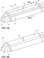
- FIG. 2A which shows the lifter 50 at a maximum height
- FIG. 2B which shows the lifter 50 at a minimum height.
- the lifter 50 can be fixedly positioned at any location between the maximum and minimum height positions, including the maximum and minimum heights. For purposes of simplicity only two such positions, first and second positions, will be described and correspond to the maximum and minimum heights, with it being understood many more positions/heights are contemplated.
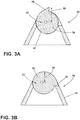
- the lifter 50 includes a housing 51 to which is moveably mounted an adjustable element 52. While any type of movable mounting is contemplated, the adjustable element 52 is illustrated as being rotatably mounted to the housing 51 for rotation about a rotation axis 57.
- the lifter 50 further comprises a lock 53 fixing the position of the adjustable element 52 in at least one of the first and second positions.
- the lock 53 comprises an actuator 54, which can be conveniently located on a portion of the lifter 50 facing the access opening 22 of the treating chamber 14.
- the lock 53 can be in the form of a conventional detent mechanism to prevent unexpected rotary movement of the adjustable element in the first and second positions. Any other type of known lock can be used.
- the adjustable element 52 comprises a main body 56 and a ridge 58 projecting from the main body 56.
- the adjustable element 52 has an asymmetrical body 61 wherein the asymmetrical body 61 comprises a maximum projection 55 from the drum 12, which corresponds to the ridge 58 being rotated to the first position, which defines the first effective height.
- a lesser projection 59 of the asymmetrical body 61 relative to the drum 12 occurs when the ridge 58 is rotated to the second position, with the projection 59 defining a second height in the second position that is less than the first height in the first position.
- the shape of the body 56 is such that the adjustable element is complementary in shape to the lifter housing 51 in the second position.
- the complementary shapes provide for a flush receipt of the ridge 58 with the housing 51 in the second position to prevent the ridge 58 from inadvertently catching laundry items in the second position.
- the first position for the adjustable element 52 can be thought of as a use position and the second position can be thought of as a stored position.
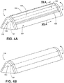
- FIG. 4A A second embodiment of the lifter 150 is illustrated in FIG. 4A .
- the second embodiment is similar to the first embodiment, with it being understood that the description of the like parts of the first embodiment applies to the additional embodiments, unless otherwise noted.
- numerals for elements of the second embodiment similar to the first embodiment will be increased by 100.
- the second embodiment of the lifter 150 is similar to the first embodiment 50, in that it comprises an adjustable element 152 rotatable about a rotation axis 157 and a locking mechanism 153 with an actuator 154.
- the adjustable element 152 is rotatably mounted to the lifter housing 151 and rotates between the first and second positions having first and second effective height as shown in FIG. 4A and 4B respectively.
- the lifter 150 differs in that the ridge 158 projected from the main body 156 of the adjustable element 152 is shown as having a rectangular profile.
- the lifter 152 also differs in that the ridge 158 can be received within an interior compartment 160 of the lifter 150 when the adjustable element 152 is in the second position.
- FIGS. 5A and 5B illustrate the movement of the adjustable element 152 from the first to the second positions, respectively, with FIG. 5B illustrating the receipt of the ridge 158 within the interior compartment 160.
- the ridge 158 with a rectangular profile defines the maximum height of the lifter 150 when the adjustable element 152 is rotated to the first position.
- the ridge 158 of the adjustable element 152 is received within an interior compartment 160 of the lifter 150 when the adjustable element 152 is in the second position.
- the lifter 150 can be configured to have an interior compartment 160 to accommodate the varying profile of the ridge 158 while still retaining a flush appearance from the exterior when the adjustable element 152 is in the second position.
- each lifter height and profile allow the user to adjust the amount of mechanical energy by lifting/dropping, collision and friction imparted to the laundry items as the amount of mechanical energy is related to the height of the lifter.
- a heavy-duty load can benefit from a lifter 150 setting with a higher protrusion and edged profile to create more friction during a washing cycle.
- a delicate load can benefit from a lifter 150 setting with a lower protrusion and smoother profile to prevent any damage done to the laundry during a washing cycle.
- the adjustable element in the second position being one of flush with a sidewall of the lifter or received within an interior of the lifter provide an appearance that is clean and aesthetically pleasing to the consumers.
- the lifter 50 while variable in height, can be used alone or in combination with other lifters that are fixed height or variable in height.
- a lifter for a laundry treating appliance comprises a main lifter body and an adjustable element having an asymmetrical body rotatably mounted to the main lifter body for rotation between first and second positions.
- the asymmetrical body comprises a maximum projection radially furthest from the rotation axis, a lesser projection radially closer to the rotation axis than the maximum projection, and in the first position the maximum projection defines a first maximum height, and in the second position, the lesser projection defines a second maximum height less than the first maximum height.
- the lifter wherein the maximum projection is at least one of flush with a sidewall of the lifter or received within an interior of the lifter when the adjustable element is in the second position.
- the lifter can further comprise a lock fixing the adjustable element in at least one of the first and second positions.
- the lifter wherein the lock comprises an actuator located on an end of the lifter facing the access opening.
Landscapes
- Engineering & Computer Science (AREA)
- Textile Engineering (AREA)
- Main Body Construction Of Washing Machines And Laundry Dryers (AREA)
- Accessory Of Washing/Drying Machine, Commercial Washing/Drying Machine, Other Washing/Drying Machine (AREA)
Applications Claiming Priority (1)
| Application Number | Priority Date | Filing Date | Title |
|---|---|---|---|
| US15/299,957 US10508377B2 (en) | 2016-10-21 | 2016-10-21 | Laundry treating appliance with an adjustable height lifter |
Publications (2)
| Publication Number | Publication Date |
|---|---|
| EP3312332A1 true EP3312332A1 (fr) | 2018-04-25 |
| EP3312332B1 EP3312332B1 (fr) | 2020-07-01 |
Family
ID=60153182
Family Applications (1)
| Application Number | Title | Priority Date | Filing Date |
|---|---|---|---|
| EP17197549.3A Active EP3312332B1 (fr) | 2016-10-21 | 2017-10-20 | Appareil de traitement du linge avec un poussoir réglable en hauteur |
Country Status (2)
| Country | Link |
|---|---|
| US (3) | US10508377B2 (fr) |
| EP (1) | EP3312332B1 (fr) |
Cited By (1)
| Publication number | Priority date | Publication date | Assignee | Title |
|---|---|---|---|---|
| EP3608466A1 (fr) * | 2018-08-09 | 2020-02-12 | E.G.O. ELEKTRO-GERÄTEBAU GmbH | Dispositif de traitement de linge et son procédé de fonctionnement |
Families Citing this family (6)
| Publication number | Priority date | Publication date | Assignee | Title |
|---|---|---|---|---|
| USD878687S1 (en) | 2017-05-31 | 2020-03-17 | Whirlpool Corporation | Fabric care appliance |
| USD899720S1 (en) * | 2017-12-21 | 2020-10-20 | Whirlpool Corporation | Laundry treating appliance |
| USD885696S1 (en) * | 2018-01-03 | 2020-05-26 | Samsung Electronics Co., Ltd. | Dryer |
| KR102767941B1 (ko) * | 2019-08-08 | 2025-02-17 | 삼성전자주식회사 | 드럼 세탁장치 |
| USD962569S1 (en) * | 2020-07-21 | 2022-08-30 | Haier Us Appliance Solutions, Inc. | Front load washer vent |
| CN115387082B (zh) * | 2022-09-21 | 2025-04-11 | 珠海格力电器股份有限公司 | 内筒组件和具有其的洗衣机 |
Citations (4)
| Publication number | Priority date | Publication date | Assignee | Title |
|---|---|---|---|---|
| JPS5670793A (en) * | 1979-11-16 | 1981-06-12 | Hitachi Ltd | Lifter device for drum type washing machine |
| JPH0433689A (ja) * | 1990-05-29 | 1992-02-05 | Matsushita Electric Ind Co Ltd | ドラム式洗濯機 |
| US20040118168A1 (en) * | 2002-09-25 | 2004-06-24 | Lg Electronics Inc. | Lift of drum-type washing machine and drum-type washing machine using the same |
| EP2053152A1 (fr) * | 2007-10-19 | 2009-04-29 | Whirpool Corporation | Lave-linge ou sèche-linge doté d'un tambour avec éléments de relèvement amovibles |
Family Cites Families (5)
| Publication number | Priority date | Publication date | Assignee | Title |
|---|---|---|---|---|
| AU2004203379B2 (en) | 2003-07-28 | 2006-10-12 | Lg Electronics Inc. | Washing machine |
| KR20050082930A (ko) | 2004-02-20 | 2005-08-24 | 린나이코리아 주식회사 | 드럼용 리프터 |
| KR100701174B1 (ko) | 2005-06-27 | 2007-03-28 | 주식회사 대우일렉트로닉스 | 보조 리프터를 갖는 드럼세탁기 |
| IT1394949B1 (it) | 2009-07-27 | 2012-07-27 | Indesit Co Spa | Macchina per il lavaggio di biancheria a caricamento frontale |
| BR112012005026B1 (pt) * | 2009-09-10 | 2020-04-07 | Illinois Tool Works | trava de porta para uma porta de um utensílio |
-
2016
- 2016-10-21 US US15/299,957 patent/US10508377B2/en not_active Expired - Fee Related
-
2017
- 2017-10-20 EP EP17197549.3A patent/EP3312332B1/fr active Active
-
2019
- 2019-11-26 US US16/695,812 patent/US11198966B2/en not_active Expired - Fee Related
-
2021
- 2021-11-23 US US17/533,761 patent/US20220081820A1/en not_active Abandoned
Patent Citations (4)
| Publication number | Priority date | Publication date | Assignee | Title |
|---|---|---|---|---|
| JPS5670793A (en) * | 1979-11-16 | 1981-06-12 | Hitachi Ltd | Lifter device for drum type washing machine |
| JPH0433689A (ja) * | 1990-05-29 | 1992-02-05 | Matsushita Electric Ind Co Ltd | ドラム式洗濯機 |
| US20040118168A1 (en) * | 2002-09-25 | 2004-06-24 | Lg Electronics Inc. | Lift of drum-type washing machine and drum-type washing machine using the same |
| EP2053152A1 (fr) * | 2007-10-19 | 2009-04-29 | Whirpool Corporation | Lave-linge ou sèche-linge doté d'un tambour avec éléments de relèvement amovibles |
Cited By (3)
| Publication number | Priority date | Publication date | Assignee | Title |
|---|---|---|---|---|
| EP3608466A1 (fr) * | 2018-08-09 | 2020-02-12 | E.G.O. ELEKTRO-GERÄTEBAU GmbH | Dispositif de traitement de linge et son procédé de fonctionnement |
| CN110863322A (zh) * | 2018-08-09 | 2020-03-06 | E.G.O.电气设备制造股份有限公司 | 衣物处理装置及其操作方法 |
| CN110863322B (zh) * | 2018-08-09 | 2023-05-30 | E.G.O.电气设备制造股份有限公司 | 衣物处理装置及其操作方法 |
Also Published As
| Publication number | Publication date |
|---|---|
| EP3312332B1 (fr) | 2020-07-01 |
| US20220081820A1 (en) | 2022-03-17 |
| US20200095717A1 (en) | 2020-03-26 |
| US10508377B2 (en) | 2019-12-17 |
| US20180112342A1 (en) | 2018-04-26 |
| US11198966B2 (en) | 2021-12-14 |
Similar Documents
| Publication | Publication Date | Title |
|---|---|---|
| US11198966B2 (en) | Laundry treating appliance with an adjustable height lifter | |
| US11834769B2 (en) | Laundry treating appliance with dispenser having a siphon cap | |
| US11591739B2 (en) | Laundry treating appliance detergent dispenser | |
| US9828714B2 (en) | Laundry treating appliance with a static tub | |
| EP3663456B1 (fr) | Appareil de traitement du linge doté d'un ensemble de bras de pulvérisation | |
| US11591744B2 (en) | Laundry treating appliance having a hinge assembly | |
| US11725332B2 (en) | Laundry treating appliance having a hinge assembly | |
| US20200157728A1 (en) | Laundry treating appliance having a door assembly | |
| US9534334B2 (en) | Laundry treating appliance with a suspension assembly and a suspension assembly | |
| US20180073183A1 (en) | Laundry treating appliance and dispenser | |
| CN110741118B (zh) | 衣物处理设备及其控制方法 | |
| US11773527B2 (en) | Laundry treating appliance and dispenser | |
| US11162208B2 (en) | Clothes processing apparatus and control method therefor | |
| AU2018296986B2 (en) | Clothes processing apparatus and control method therefor | |
| US20240352647A1 (en) | Laundry treating appliance and corresponding dispenser |
Legal Events
| Date | Code | Title | Description |
|---|---|---|---|
| PUAI | Public reference made under article 153(3) epc to a published international application that has entered the european phase |
Free format text: ORIGINAL CODE: 0009012 |
|
| STAA | Information on the status of an ep patent application or granted ep patent |
Free format text: STATUS: THE APPLICATION HAS BEEN PUBLISHED |
|
| AK | Designated contracting states |
Kind code of ref document: A1 Designated state(s): AL AT BE BG CH CY CZ DE DK EE ES FI FR GB GR HR HU IE IS IT LI LT LU LV MC MK MT NL NO PL PT RO RS SE SI SK SM TR |
|
| AX | Request for extension of the european patent |
Extension state: BA ME |
|
| STAA | Information on the status of an ep patent application or granted ep patent |
Free format text: STATUS: REQUEST FOR EXAMINATION WAS MADE |
|
| 17P | Request for examination filed |
Effective date: 20181025 |
|
| RBV | Designated contracting states (corrected) |
Designated state(s): AL AT BE BG CH CY CZ DE DK EE ES FI FR GB GR HR HU IE IS IT LI LT LU LV MC MK MT NL NO PL PT RO RS SE SI SK SM TR |
|
| GRAP | Despatch of communication of intention to grant a patent |
Free format text: ORIGINAL CODE: EPIDOSNIGR1 |
|
| STAA | Information on the status of an ep patent application or granted ep patent |
Free format text: STATUS: GRANT OF PATENT IS INTENDED |
|
| RIC1 | Information provided on ipc code assigned before grant |
Ipc: D06F 58/04 20060101ALN20200323BHEP Ipc: D06F 37/06 20060101AFI20200323BHEP |
|
| RIC1 | Information provided on ipc code assigned before grant |
Ipc: D06F 37/06 20060101AFI20200327BHEP Ipc: D06F 58/04 20060101ALN20200327BHEP |
|
| INTG | Intention to grant announced |
Effective date: 20200421 |
|
| GRAS | Grant fee paid |
Free format text: ORIGINAL CODE: EPIDOSNIGR3 |
|
| GRAA | (expected) grant |
Free format text: ORIGINAL CODE: 0009210 |
|
| STAA | Information on the status of an ep patent application or granted ep patent |
Free format text: STATUS: THE PATENT HAS BEEN GRANTED |
|
| AK | Designated contracting states |
Kind code of ref document: B1 Designated state(s): AL AT BE BG CH CY CZ DE DK EE ES FI FR GB GR HR HU IE IS IT LI LT LU LV MC MK MT NL NO PL PT RO RS SE SI SK SM TR |
|
| REG | Reference to a national code |
Ref country code: CH Ref legal event code: EP Ref country code: AT Ref legal event code: REF Ref document number: 1286276 Country of ref document: AT Kind code of ref document: T Effective date: 20200715 |
|
| REG | Reference to a national code |
Ref country code: IE Ref legal event code: FG4D |
|
| REG | Reference to a national code |
Ref country code: DE Ref legal event code: R096 Ref document number: 602017018935 Country of ref document: DE |
|
| REG | Reference to a national code |
Ref country code: LT Ref legal event code: MG4D |
|
| PG25 | Lapsed in a contracting state [announced via postgrant information from national office to epo] |
Ref country code: BG Free format text: LAPSE BECAUSE OF FAILURE TO SUBMIT A TRANSLATION OF THE DESCRIPTION OR TO PAY THE FEE WITHIN THE PRESCRIBED TIME-LIMIT Effective date: 20201001 |
|
| REG | Reference to a national code |
Ref country code: NL Ref legal event code: MP Effective date: 20200701 |
|
| REG | Reference to a national code |
Ref country code: AT Ref legal event code: MK05 Ref document number: 1286276 Country of ref document: AT Kind code of ref document: T Effective date: 20200701 |
|
| PG25 | Lapsed in a contracting state [announced via postgrant information from national office to epo] |
Ref country code: CZ Free format text: LAPSE BECAUSE OF FAILURE TO SUBMIT A TRANSLATION OF THE DESCRIPTION OR TO PAY THE FEE WITHIN THE PRESCRIBED TIME-LIMIT Effective date: 20200701 Ref country code: FI Free format text: LAPSE BECAUSE OF FAILURE TO SUBMIT A TRANSLATION OF THE DESCRIPTION OR TO PAY THE FEE WITHIN THE PRESCRIBED TIME-LIMIT Effective date: 20200701 Ref country code: GR Free format text: LAPSE BECAUSE OF FAILURE TO SUBMIT A TRANSLATION OF THE DESCRIPTION OR TO PAY THE FEE WITHIN THE PRESCRIBED TIME-LIMIT Effective date: 20201002 Ref country code: NO Free format text: LAPSE BECAUSE OF FAILURE TO SUBMIT A TRANSLATION OF THE DESCRIPTION OR TO PAY THE FEE WITHIN THE PRESCRIBED TIME-LIMIT Effective date: 20201001 Ref country code: PT Free format text: LAPSE BECAUSE OF FAILURE TO SUBMIT A TRANSLATION OF THE DESCRIPTION OR TO PAY THE FEE WITHIN THE PRESCRIBED TIME-LIMIT Effective date: 20201102 Ref country code: HR Free format text: LAPSE BECAUSE OF FAILURE TO SUBMIT A TRANSLATION OF THE DESCRIPTION OR TO PAY THE FEE WITHIN THE PRESCRIBED TIME-LIMIT Effective date: 20200701 Ref country code: AT Free format text: LAPSE BECAUSE OF FAILURE TO SUBMIT A TRANSLATION OF THE DESCRIPTION OR TO PAY THE FEE WITHIN THE PRESCRIBED TIME-LIMIT Effective date: 20200701 Ref country code: LT Free format text: LAPSE BECAUSE OF FAILURE TO SUBMIT A TRANSLATION OF THE DESCRIPTION OR TO PAY THE FEE WITHIN THE PRESCRIBED TIME-LIMIT Effective date: 20200701 Ref country code: SE Free format text: LAPSE BECAUSE OF FAILURE TO SUBMIT A TRANSLATION OF THE DESCRIPTION OR TO PAY THE FEE WITHIN THE PRESCRIBED TIME-LIMIT Effective date: 20200701 Ref country code: ES Free format text: LAPSE BECAUSE OF FAILURE TO SUBMIT A TRANSLATION OF THE DESCRIPTION OR TO PAY THE FEE WITHIN THE PRESCRIBED TIME-LIMIT Effective date: 20200701 |
|
| PG25 | Lapsed in a contracting state [announced via postgrant information from national office to epo] |
Ref country code: PL Free format text: LAPSE BECAUSE OF FAILURE TO SUBMIT A TRANSLATION OF THE DESCRIPTION OR TO PAY THE FEE WITHIN THE PRESCRIBED TIME-LIMIT Effective date: 20200701 Ref country code: LV Free format text: LAPSE BECAUSE OF FAILURE TO SUBMIT A TRANSLATION OF THE DESCRIPTION OR TO PAY THE FEE WITHIN THE PRESCRIBED TIME-LIMIT Effective date: 20200701 Ref country code: RS Free format text: LAPSE BECAUSE OF FAILURE TO SUBMIT A TRANSLATION OF THE DESCRIPTION OR TO PAY THE FEE WITHIN THE PRESCRIBED TIME-LIMIT Effective date: 20200701 Ref country code: IS Free format text: LAPSE BECAUSE OF FAILURE TO SUBMIT A TRANSLATION OF THE DESCRIPTION OR TO PAY THE FEE WITHIN THE PRESCRIBED TIME-LIMIT Effective date: 20201101 |
|
| PG25 | Lapsed in a contracting state [announced via postgrant information from national office to epo] |
Ref country code: NL Free format text: LAPSE BECAUSE OF FAILURE TO SUBMIT A TRANSLATION OF THE DESCRIPTION OR TO PAY THE FEE WITHIN THE PRESCRIBED TIME-LIMIT Effective date: 20200701 |
|
| REG | Reference to a national code |
Ref country code: DE Ref legal event code: R097 Ref document number: 602017018935 Country of ref document: DE |
|
| PG25 | Lapsed in a contracting state [announced via postgrant information from national office to epo] |
Ref country code: DK Free format text: LAPSE BECAUSE OF FAILURE TO SUBMIT A TRANSLATION OF THE DESCRIPTION OR TO PAY THE FEE WITHIN THE PRESCRIBED TIME-LIMIT Effective date: 20200701 Ref country code: RO Free format text: LAPSE BECAUSE OF FAILURE TO SUBMIT A TRANSLATION OF THE DESCRIPTION OR TO PAY THE FEE WITHIN THE PRESCRIBED TIME-LIMIT Effective date: 20200701 Ref country code: EE Free format text: LAPSE BECAUSE OF FAILURE TO SUBMIT A TRANSLATION OF THE DESCRIPTION OR TO PAY THE FEE WITHIN THE PRESCRIBED TIME-LIMIT Effective date: 20200701 Ref country code: SM Free format text: LAPSE BECAUSE OF FAILURE TO SUBMIT A TRANSLATION OF THE DESCRIPTION OR TO PAY THE FEE WITHIN THE PRESCRIBED TIME-LIMIT Effective date: 20200701 |
|
| PLBE | No opposition filed within time limit |
Free format text: ORIGINAL CODE: 0009261 |
|
| STAA | Information on the status of an ep patent application or granted ep patent |
Free format text: STATUS: NO OPPOSITION FILED WITHIN TIME LIMIT |
|
| PG25 | Lapsed in a contracting state [announced via postgrant information from national office to epo] |
Ref country code: AL Free format text: LAPSE BECAUSE OF FAILURE TO SUBMIT A TRANSLATION OF THE DESCRIPTION OR TO PAY THE FEE WITHIN THE PRESCRIBED TIME-LIMIT Effective date: 20200701 |
|
| REG | Reference to a national code |
Ref country code: CH Ref legal event code: PL |
|
| 26N | No opposition filed |
Effective date: 20210406 |
|
| PG25 | Lapsed in a contracting state [announced via postgrant information from national office to epo] |
Ref country code: MC Free format text: LAPSE BECAUSE OF FAILURE TO SUBMIT A TRANSLATION OF THE DESCRIPTION OR TO PAY THE FEE WITHIN THE PRESCRIBED TIME-LIMIT Effective date: 20200701 Ref country code: LU Free format text: LAPSE BECAUSE OF NON-PAYMENT OF DUE FEES Effective date: 20201020 Ref country code: SK Free format text: LAPSE BECAUSE OF FAILURE TO SUBMIT A TRANSLATION OF THE DESCRIPTION OR TO PAY THE FEE WITHIN THE PRESCRIBED TIME-LIMIT Effective date: 20200701 |
|
| REG | Reference to a national code |
Ref country code: BE Ref legal event code: MM Effective date: 20201031 |
|
| PG25 | Lapsed in a contracting state [announced via postgrant information from national office to epo] |
Ref country code: BE Free format text: LAPSE BECAUSE OF NON-PAYMENT OF DUE FEES Effective date: 20201031 Ref country code: CH Free format text: LAPSE BECAUSE OF NON-PAYMENT OF DUE FEES Effective date: 20201031 Ref country code: SI Free format text: LAPSE BECAUSE OF FAILURE TO SUBMIT A TRANSLATION OF THE DESCRIPTION OR TO PAY THE FEE WITHIN THE PRESCRIBED TIME-LIMIT Effective date: 20200701 Ref country code: LI Free format text: LAPSE BECAUSE OF NON-PAYMENT OF DUE FEES Effective date: 20201031 |
|
| PG25 | Lapsed in a contracting state [announced via postgrant information from national office to epo] |
Ref country code: IE Free format text: LAPSE BECAUSE OF NON-PAYMENT OF DUE FEES Effective date: 20201020 |
|
| PG25 | Lapsed in a contracting state [announced via postgrant information from national office to epo] |
Ref country code: TR Free format text: LAPSE BECAUSE OF FAILURE TO SUBMIT A TRANSLATION OF THE DESCRIPTION OR TO PAY THE FEE WITHIN THE PRESCRIBED TIME-LIMIT Effective date: 20200701 Ref country code: MT Free format text: LAPSE BECAUSE OF FAILURE TO SUBMIT A TRANSLATION OF THE DESCRIPTION OR TO PAY THE FEE WITHIN THE PRESCRIBED TIME-LIMIT Effective date: 20200701 Ref country code: CY Free format text: LAPSE BECAUSE OF FAILURE TO SUBMIT A TRANSLATION OF THE DESCRIPTION OR TO PAY THE FEE WITHIN THE PRESCRIBED TIME-LIMIT Effective date: 20200701 |
|
| PG25 | Lapsed in a contracting state [announced via postgrant information from national office to epo] |
Ref country code: MK Free format text: LAPSE BECAUSE OF FAILURE TO SUBMIT A TRANSLATION OF THE DESCRIPTION OR TO PAY THE FEE WITHIN THE PRESCRIBED TIME-LIMIT Effective date: 20200701 |
|
| PGFP | Annual fee paid to national office [announced via postgrant information from national office to epo] |
Ref country code: GB Payment date: 20220901 Year of fee payment: 6 |
|
| PGFP | Annual fee paid to national office [announced via postgrant information from national office to epo] |
Ref country code: FR Payment date: 20220908 Year of fee payment: 6 |
|
| PGFP | Annual fee paid to national office [announced via postgrant information from national office to epo] |
Ref country code: IT Payment date: 20220913 Year of fee payment: 6 Ref country code: DE Payment date: 20220831 Year of fee payment: 6 |
|
| P01 | Opt-out of the competence of the unified patent court (upc) registered |
Effective date: 20230522 |
|
| REG | Reference to a national code |
Ref country code: DE Ref legal event code: R119 Ref document number: 602017018935 Country of ref document: DE |
|
| GBPC | Gb: european patent ceased through non-payment of renewal fee |
Effective date: 20231020 |
|
| PG25 | Lapsed in a contracting state [announced via postgrant information from national office to epo] |
Ref country code: GB Free format text: LAPSE BECAUSE OF NON-PAYMENT OF DUE FEES Effective date: 20231020 |
|
| PG25 | Lapsed in a contracting state [announced via postgrant information from national office to epo] |
Ref country code: GB Free format text: LAPSE BECAUSE OF NON-PAYMENT OF DUE FEES Effective date: 20231020 Ref country code: FR Free format text: LAPSE BECAUSE OF NON-PAYMENT OF DUE FEES Effective date: 20231031 Ref country code: DE Free format text: LAPSE BECAUSE OF NON-PAYMENT OF DUE FEES Effective date: 20240501 |
|
| PG25 | Lapsed in a contracting state [announced via postgrant information from national office to epo] |
Ref country code: IT Free format text: LAPSE BECAUSE OF NON-PAYMENT OF DUE FEES Effective date: 20231020 |
|
| PG25 | Lapsed in a contracting state [announced via postgrant information from national office to epo] |
Ref country code: IT Free format text: LAPSE BECAUSE OF NON-PAYMENT OF DUE FEES Effective date: 20231020 |