EP3312357A1 - Système de réalisation d'un environnement au moins partiellement fermé utilisant des vitres, des panneaux ou similaires - Google Patents
Système de réalisation d'un environnement au moins partiellement fermé utilisant des vitres, des panneaux ou similaires Download PDFInfo
- Publication number
- EP3312357A1 EP3312357A1 EP17197754.9A EP17197754A EP3312357A1 EP 3312357 A1 EP3312357 A1 EP 3312357A1 EP 17197754 A EP17197754 A EP 17197754A EP 3312357 A1 EP3312357 A1 EP 3312357A1
- Authority
- EP
- European Patent Office
- Prior art keywords
- panels
- pin
- lower plate
- members
- plate
- Prior art date
- Legal status (The legal status is an assumption and is not a legal conclusion. Google has not performed a legal analysis and makes no representation as to the accuracy of the status listed.)
- Granted
Links
Images






Classifications
-
- E—FIXED CONSTRUCTIONS
- E04—BUILDING
- E04B—GENERAL BUILDING CONSTRUCTIONS; WALLS, e.g. PARTITIONS; ROOFS; FLOORS; CEILINGS; INSULATION OR OTHER PROTECTION OF BUILDINGS
- E04B2/00—Walls, e.g. partitions, for buildings; Wall construction with regard to insulation; Connections specially adapted to walls
- E04B2/74—Removable non-load-bearing partitions; Partitions with a free upper edge
- E04B2/7401—Removable non-load-bearing partitions; Partitions with a free upper edge assembled using panels without a frame or supporting posts, with or without upper or lower edge locating rails
- E04B2/7405—Removable non-load-bearing partitions; Partitions with a free upper edge assembled using panels without a frame or supporting posts, with or without upper or lower edge locating rails with free upper edge, e.g. for use as office space dividers
-
- E—FIXED CONSTRUCTIONS
- E06—DOORS, WINDOWS, SHUTTERS, OR ROLLER BLINDS IN GENERAL; LADDERS
- E06B—FIXED OR MOVABLE CLOSURES FOR OPENINGS IN BUILDINGS, VEHICLES, FENCES OR LIKE ENCLOSURES IN GENERAL, e.g. DOORS, WINDOWS, BLINDS, GATES
- E06B3/00—Window sashes, door leaves, or like elements for closing wall or like openings; Layout of fixed or moving closures, e.g. windows in wall or like openings; Features of rigidly-mounted outer frames relating to the mounting of wing frames
- E06B3/54—Fixing of glass panes or like plates
- E06B3/5454—Fixing of glass panes or like plates inside U-shaped section members
-
- E—FIXED CONSTRUCTIONS
- E06—DOORS, WINDOWS, SHUTTERS, OR ROLLER BLINDS IN GENERAL; LADDERS
- E06B—FIXED OR MOVABLE CLOSURES FOR OPENINGS IN BUILDINGS, VEHICLES, FENCES OR LIKE ENCLOSURES IN GENERAL, e.g. DOORS, WINDOWS, BLINDS, GATES
- E06B3/00—Window sashes, door leaves, or like elements for closing wall or like openings; Layout of fixed or moving closures, e.g. windows in wall or like openings; Features of rigidly-mounted outer frames relating to the mounting of wing frames
- E06B3/66—Units comprising two or more parallel glass or like panes permanently secured together
- E06B3/663—Elements for spacing panes
- E06B3/66309—Section members positioned at the edges of the glazing unit
- E06B3/66314—Section members positioned at the edges of the glazing unit of tubular shape
-
- E—FIXED CONSTRUCTIONS
- E04—BUILDING
- E04B—GENERAL BUILDING CONSTRUCTIONS; WALLS, e.g. PARTITIONS; ROOFS; FLOORS; CEILINGS; INSULATION OR OTHER PROTECTION OF BUILDINGS
- E04B2/00—Walls, e.g. partitions, for buildings; Wall construction with regard to insulation; Connections specially adapted to walls
- E04B2/74—Removable non-load-bearing partitions; Partitions with a free upper edge
- E04B2/82—Removable non-load-bearing partitions; Partitions with a free upper edge characterised by the manner in which edges are connected to the building; Means therefor; Special details of easily-removable partitions as far as related to the connection with other parts of the building
- E04B2/825—Removable non-load-bearing partitions; Partitions with a free upper edge characterised by the manner in which edges are connected to the building; Means therefor; Special details of easily-removable partitions as far as related to the connection with other parts of the building the connection between the floor and the ceiling being achieved without any restraining forces acting in the plane of the partition
-
- E—FIXED CONSTRUCTIONS
- E06—DOORS, WINDOWS, SHUTTERS, OR ROLLER BLINDS IN GENERAL; LADDERS
- E06B—FIXED OR MOVABLE CLOSURES FOR OPENINGS IN BUILDINGS, VEHICLES, FENCES OR LIKE ENCLOSURES IN GENERAL, e.g. DOORS, WINDOWS, BLINDS, GATES
- E06B3/00—Window sashes, door leaves, or like elements for closing wall or like openings; Layout of fixed or moving closures, e.g. windows in wall or like openings; Features of rigidly-mounted outer frames relating to the mounting of wing frames
- E06B3/54—Fixing of glass panes or like plates
- E06B3/5436—Fixing of glass panes or like plates involving holes or indentations in the pane
-
- E—FIXED CONSTRUCTIONS
- E06—DOORS, WINDOWS, SHUTTERS, OR ROLLER BLINDS IN GENERAL; LADDERS
- E06B—FIXED OR MOVABLE CLOSURES FOR OPENINGS IN BUILDINGS, VEHICLES, FENCES OR LIKE ENCLOSURES IN GENERAL, e.g. DOORS, WINDOWS, BLINDS, GATES
- E06B3/00—Window sashes, door leaves, or like elements for closing wall or like openings; Layout of fixed or moving closures, e.g. windows in wall or like openings; Features of rigidly-mounted outer frames relating to the mounting of wing frames
- E06B3/66—Units comprising two or more parallel glass or like panes permanently secured together
- E06B3/6621—Units comprising two or more parallel glass or like panes permanently secured together with special provisions for fitting in window frames or to adjacent units; Separate edge protecting strips
Definitions
- the present invention relates to the sector of dividing walls and in particular relates to a system for making an at least partially closed environment, for example a box or the like, using panes of glass, panels or the like.
- the walls are made of glass it is necessary for the walls to be arranged in a perfectly vertical position. This often is problematic because the floor may have depressions or areas which are slightly higher than the rest of the floor.
- EP 1 630 312 A1 discloses a connector for panel walls or the like of wood, pressing chip, hard fiber or other materials, such as are used, for example, in the construction of measuring stands.
- GB 2 305 205 A discloses a combined double glazing spacer and mounting section.
- DE 10 2005 027528 A1 discloses a wall system for exhibition booths.
- the system comprises multiple intrinsically rigid wall elements that are magnetically joined together at vertical frame legs.
- the aim of the Applicant is to provide a novel system for making an environment which is at least partially closed using panels or panes, which is practical, solid, reliable and is able to overcome at least some of the aforementioned problems.
- the Applicant has noticed that the solution described in EP 1 630 312 A1 does not allow to create a solid base arranged horizontally with respect to the surface where the structure has to be mounted.
- the Applicant has noted that the solution disclosed in EP 1 630 312 A1 provides for support points and does not provide a base structure which forms a closed loop or an open loop.
- a lower plate which is shaped as a closed loop or an open loop.
- the language "closed loop” will indicate that the lower plate is loop closed and that neither a starting point nor an end point can be identified.
- a closed loop shape is a circular shape, an oval shape, an elliptic shape, a square shape, a rectangular shape, or the shape of any polygon (either regular or not).
- the language "open loop” will indicate that the lower plate forms a closed loop except for an open length.
- Such an open length has a length which is lower than half of the base perimeter. Preferably, it is lower than 40%, more preferably lower than 30%, more preferably lower than 20% and still more preferably, lower than 10%.
- the base plate according to the present invention is very stable and it can be arranged perfectly horizontal in a practical and efficient manner.
- an installer can regulate the height through the pin-like members, in particular on those which are adjustable heightwise simply by a screwdriver or an hexagonal key or any other similar tool.
- the installer can start to regulate the height of the pin-like members clockwise or anticlockwise and then make the further regulations up to the starting point.
- the base plate can also be moved fromj a point to another point of a certain environment (for instance in case there is a change of layout).
- the installer and/or the designer has the possibility to decide where an opening should be provided.
- fixed pin-like members Preferably, there are provided fixed pin-like members. They preferably provide alignment means but they do not operate as supporting means. In other words, the panels preferably are supported on the base plate and not on the top ends of the pin-like members.
- the present invention relates to a system for making an at least partially closed environment using a plurality of panels, the system comprising:
- said rotation means comprise, on the top of said first and second pin-like members, an incision (shaped as a blade head or cross head) for a screwdriver or with a hexagonal socket for a hexagonal key (such as a Allen key).
- an incision shaped as a blade head or cross head
- a hexagonal socket for a hexagonal key (such as a Allen key).
- said pin-like stability and alignment members comprise first and second threaded pins and said lower plate comprises through-holes suitable for receiving said first and second threaded pins, wherein said first threaded pins have a thread which allows screwing of said first pins so that they project also partly downwards, and wherein said second threaded pins have a thread which allows them to be screwed so that they do not project downwards, the upwardly projecting ends at least of said second pins forming a discrete alignment element.
- the lower plate preferably comprises separate modular sections joinable together to form said lower plate which is shaped in a closed loop or an open loop.
- the adjacent separate sections of lower plate are joinable together with a key which is configured to engage a recess of a plate section and a recess of the adjacent plate section.
- Each of said panels may comprise two individual panes and a perimetral frame.
- the two individual panes are arranged facing one another and define, together with said perimetral frame, a closed chamber.
- connection means for connecting said panels at the top comprise an upper plate in one piece or formed by separate modular sections joinable together to form a closed-loop or an open-loop upper plate.
- the adjacent sections of upper plate are joinable with a key which is configured to engage a recess of a plate section and a recess of the adjacent plate section.
- the upper plate comprises slots, each slot comprising an enlarged part and a straight part of smaller width than the enlarged part.
- At least two of said panels may comprise a profile comprising an upper groove for receiving and holding a pane.
- the system may further comprise a clamp for joining a panel with an adjacent panel, wherein said clamp comprises two retaining members and a connecting pin for connecting together said two retaining members, wherein said retaining members are partially or completely recessed in said panels.
- an at least partially closed environment made using a system of the aforementioned type.
- a lower plate, two or more panels supported by the lower plate and upper connection means for connecting two or more panels at the top are provided.
- the upper connection means comprise an upper plate connected to the panels.
- the panels are joined together by means of a clamp.
- the lower plate may be formed by a single plate shaped in a closed loop (for example in the form of a rectangle, a circle, an ellipse or the like) or in an open loop (for example C, U or L shaped).
- the lower plate comprises two or more modules which can be connected together in a permanent or removable manner.
- modules which are identical to each other are provided.
- modules of at least two types are provided so as to form a closed-loop or open-loop plate.
- the linear module 11 could have a length of 100 cm and the curved module 12 a radius of about 100 cm.
- the lower plate 10 could have a width of a few centimetres, for example 5-13 cm or more, for instance 5-10 cm.
- the lower plate 10 could be advantageously made of iron, steel, aluminium, thermoplastic material, reinforced (for instance by fibers) composite material or metal alloys.
- the lower plate 10 comprises a plurality of holes 13.
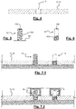
- Figure 4 shows a cross-section along an axis of a hole 13 in the lower plate (11 or 12).
- the holes 13 are equidistant. For example, they may be at a few centimetres distance from each other.
- the holes 13 have a diameter of a few millimetres, for example 10-15 mm and are threaded.
- they are through-holes as shown in Figure 4 .
- Threaded pins 15, 16 are screwed inside at least a part of the holes.
- Figures 5 and 6 show, respectively, an adjustable pin 15 and a fixed pin 16.
- the adjustable pin 15 has a flat, wide, washer-like, bottom head 151 and a top end with an incision 152 for a screwdriver or with a hexagonal socket for a hexagonal key (such as an Allen key) or the like.
- a hexagonal key such as an Allen key
- the washer head 151 projects downwards and correspondingly raises the lower plate 11, 12. This condition is visible in Figure 7.2 .
- This functional feature is particular advantageous since it allows adjustments to be made for small differences in height of the floor. In this way, the lower plate is extremely stable. If instead the floor is perfectly flat ( Figure 7.1 ), the pins 15, 16 project upwards by the same height.
- the fixed pin 16 also has an end with an incision 162 for a screwdriver or with a hexagonal socket for a hexagonal key (such as an Allen key) or the like.
- the incision (or hexagonal socket) 162 allows the fixed pin 16 to be screwed in position.
- the length of the thread 163 is chosen so as to cause penetration of the fixed pin 16 inside the respective hole 13 only by the desired amount, so as not to project downwards.
- the projecting part of the fixed pins 16 and of the adjustable pins 15 has the same length.
- the ends of the pins 15, 16 lie in a same plane.
- This condition is obtained using any known means, for example by means of a laser instrument.
- the same laser instrument may be used to check that, after the adjustments performed with the adjustable pins 15, the fixed pins 16 lie in a perfectly horizontal plane.
- the fixed pins 16 (and in certain cases at least some of the adjustable pins 15) form a centring and alignment member which is discrete, i.e. not continuous, but formed by a plurality of aligned single support pins.
- the centring and alignment member overall is configured to centre and align one or more panes or sheets. Owing to the levelling action performed by means of the adjustable pins (which function as adjustable feet), the panels 20 are supported so as to be perfectly horizontal.
- the panels 20 are configured so as to cooperate with the pins 15, 16 of the lower plate 10.
- Each panel 20 comprises a lower profile 40 or a perimetral frame 30 shaped so as to cooperate with said pins 15, 16.
- Panel comprising a double-glazing pane
- Figure 8 shows, cross-sectioned, a double-glazing pane according to an embodiment of the present invention.
- the double-glazing pane is indicated overall by 20 and comprises two single panes 21, 22 of glass facing each other and parallel.
- Each single glass pane 21, 22 comprises an outer side 21o and 22o and an inner side 21i and 22i.
- the double-glazing pane 20 also comprises a perimetral frame 30.
- the perimetral frame 30 extends along all the sides of the double-glazing pane 20 and keeps the two single glass panes 21, 22 spaced from each other.
- An interspace or closed chamber 23 is therefore formed between the two single glass panes 21, 22.
- the closed chamber 23 is therefore defined by the inner sides 21i, 22i of the two single panes 21, 22 and by the frame 30.
- the frame 30 is preferably a suitably shaped, extruded, metal body. Suitable metals may be chosen from the group comprising aluminium, aluminium alloy, steel, stainless steel or combinations thereof.
- the frame 30 may be made by means of moulding using a plastic material, for example PE (polyethylene), PP (polypropylene) or PET (polyethylene terephthalate) or a composite material.
- a plastic material for example PE (polyethylene), PP (polypropylene) or PET (polyethylene terephthalate) or a composite material.
- the frame 30 comprises a central body 32, a salt-containing compartment 34 and an outer engaging channel 38.
- the central body 32 defines the distance between the two single glass panes and comprises two surfaces 33 for gluing two corresponding strips of the inner side 21i, 22i of the two single glass panes 21, 22.
- each of the gluing surfaces 33 may have a width of a few centimetres (for example 2-5 cm).
- the frame 30 comprises an internal compartment 34 containing dehydrating salts.
- the salt-containing compartment 34 is preferably formed by two parallel flanges 36 configured to retain a strip of dehydrating salts 35 to prevent the formation of condensation. If the double-glazing unit of the present invention is to be used in internal environments, the salts may not be provided. However, they prevent the formation of condensation for example owing to a difference in temperature between the two single glass panes.
- the frame 30 comprises an engaging and/or coupling channel 38.
- the channel 38 is an outwardly open channel and has preferably a roughly rectangular cross-section.
- the outward opening 381 is partially closed by two teeth 382 which reduce the opening 381 of the channel 38.
- This form of the channel is able to retain a member inside it.
- a nut or a washer with a threaded hole, a pin or a screw may be retained inside it.
- the pins 15, 16 of the lower plate 10 may be inserted inside the opening 381 of the channel 38, as shown in Figure 2 .
- the ends of the pins 15, 16 act essentially as engaging members and ensure centring and alignment of the panels.
- the ends of the pins 15, 16 are not in contact with the bottom of the channel 38 and do not act as a support.
- This allows a double-glazing unit 20 according to the invention to be fixed to a floor (or to a lower plate 10), to a ceiling (or to an upper plate 50) or to a vertical upright.
- the vertical upright could be symmetrically shaped so as to connect two double-glazing panes 20 according to the invention.
- the shaped channel 38 along the entire perimetral edge of the double-glazing pane 20 also allows hinges or other closing/plugging members to be installed.
- the channel 38 is partially recessed inside the central body 32 and partly projects therefrom.
- two zones 39 are formed, these being suitable for holding a sealant able to ensure an effective sealing action along the entire perimeter of the double-glazing unit 20, in addition to the sealing provided by the adhesive used to glue the two single panes to the frame.
- the sealant may be any known sealant, preferably a substance such as silicone or a similar mono or bicomponent.
- the double-glazing pane according to the present invention is a flat pane.
- the double-glazing pane is a curved pane and the frame is suitably curved to follow the desired curvature of the double-glazing pane. In this way curved dividing walls may be provided.
- the teeth 382 may be continuous, as shown in Figure 9 , or may be discontinuous, as shown in Figure 10 .
- the embodiment of Figure 10 also has sections without teeth so as to allow easy insertion of a member (for example a nut or a washer) or any opposition member for fixing the double-glazing pane (for example) to an upright, to a plate or to a hinge.
- Figure 11 shows an alternative to the embodiment in which the channel 38 is provided.
- This embodiment has holes 38, which are preferably threaded, for fixing a hinge, an upright, a plate or the like.
- the holes 38 are equidistant.
- an upper plate 50 is provided for connecting at the top two or more panels, for example two double-glazing panes 20, as described above.
- the upper plate may also be formed by a single plate shaped in a closed loop (for example in the form of a rectangle, an ellipse or the like) or in an open loop (for example C, U or L shaped).
- a closed loop for example in the form of a rectangle, an ellipse or the like
- an open loop for example C, U or L shaped
- the upper plate 50 comprises two or more modules which can be connected together in a permanent or removable manner.
- modules which are identical to each other are provided.
- modules of at least two types are provided so as to form a closed-loop or an open-loop upper plate 50.
- the linear module 51 could have a length of 100 cm and the curved module 52 a radius of about 100 cm.
- the upper plate 50 could have a width of a few centimetres, for example 5-10 cm or more.
- the upper plate 50 could be advantageously made of iron, steel, aluminium or metal alloys.
- the upper plate 50 comprises a plurality of slots 53.
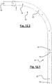
- Figure 13 shows a top plan view of an upper plate section (51, 52) mounted on a double-glazing unit 20 as described above.
- the slots 53 comprise a circular part 531 with a certain diameter and a straight section 532 with a width smaller than the diameter of the circular part.
- the slots 53 are through-slots.
- Figures 14 and 15 show in schematic form a way of fixing the upper plate 50 to the double-glazing unit 20.
- a washer with a threaded hole or a nut is preferably inserted inside the channel 38 of the perimetral frame 30.
- the upper plate 50 is rested on top of the double-glazing unit 20 and a screw 55 is inserted inside the slot 53 (vertical arrow in Figure 15 ).
- the straight section 532 of the slot 53 allows centring of the threaded hole of the washer or the nut (as suggested by the horizontal arrow, pointing to the right, in Figure 15 ).
- Figures 16A, 16B and 16C show schematically how two sections (for example 11 and 12) of the lower plate and/or the upper plate (for example 51 and 52) may be connected together according to embodiments of the present invention.
- the sections of the lower plate and the upper plate terminate in two recesses (14 and 54, respectively).
- the recesses are shaped in the same manner.
- each recess 14, 54 has an enlarged head and a narrower neck.
- a symmetrical key 60 with two enlarged heads 61 at the ends and a double neck 62 is provided.
- the key is configured so as to be inserted with precision inside the recesses 14, 54 of the two plate sections so as to ensure precise fastening.
- the key 60 has at least one threaded hole 63.
- a screw (not shown) may be inserted in order to extract the key 60 when it is required to disassemble the lower plate 10 and/or the upper plate 50.
- FIG. 1 shows a box which can be made with a lower plate 10, a number of double-glazing panes 20 and, optionally, an upper plate 50.
- Some double-glazing panes 20 are flat, while other units are curved.
- the (upper and lower) plates allow a large degree of modularity and adaptability.
- the curved sections of the lower plate (and the respective curved double-glazing panels) ensure a high degree of stability also when the box is formed in an open loop. However, it is preferable (for stability reasons) to have a lower plate and an upper plate in a closed loop.
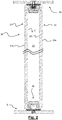
- Figure 1 shows a cross-section through the lower plate 10, the double-glazing unit 20 and the upper plate 50.
- Panels with a single-thickness pane or sheet 23 may be associated with a lower plate 10 such as that described above.
- Figure 18 shows the bottom part of a panel according to a second embodiment of the present invention.
- the panel 20 comprises a shaped lower profile 40 and a glass pane 23 (or sheet of other material).
- the profile 40 has a cross-section which is similar to that of the double-glazing unit of Figure 8 , at least as regards the bottom part of the profile which is configured to engage with the pins 15, 16 of the lower plate 10.
- the profile 40 is preferably a suitably shaped, extruded, metal body.
- Suitable metals may be chosen from the group comprising aluminium, aluminium alloy, steel, stainless steel or combinations thereof.
- the profile 40 may be made by means of moulding using a plastic material, for example PE (polyethylene), PP (polypropylene) or PET (polyethylene terephthalate) or a composite material.
- a plastic material for example PE (polyethylene), PP (polypropylene) or PET (polyethylene terephthalate) or a composite material.
- the profile 40 comprises a central body 42, a bottom engaging/coupling channel 48 and a top cavity 49.
- the profile 40 comprises an engaging and/or coupling channel 48.
- the channel 48 is a downwardly open channel and has preferably a roughly rectangular cross-section.
- the downward opening 481 is partially closed by two teeth 482 which reduce the opening of the channel.
- the shape of the channel allows a member to be retained inside it.
- a nut or a washer with a threaded hole, a pin or a screw may be retained inside the channel 48.
- the pins 15, 16 of the lower plate 10 may be inserted inside the opening 481 of the channel 48, as shown in Figure 18 .
- the ends of the pins 15, 16 act essentially as engaging members and ensure centring and alignment of the panels.
- the ends of the pins 15, 16 are not in contact with the bottom of the channel 48 and do not act as a support. This allows a panel 20 according to the invention to be fixed to a floor (or to a lower plate 10 resting on the floor), to the ceiling (or to an upper plate 50).
- the teeth 482 may be continuous or may be discontinuous.
- the bottom part of the profile could be solid with holes, preferably threaded holes, for fixing a hinge, an upright, a plate or the like.
- the holes are equidistant.
- the profile also comprises a U-shaped groove 49 for retaining the pane or sheet.
- a U-shaped groove 49 for retaining the pane or sheet.
- two seats 491 are provided for two seals (not shown) so that the glass pane is firmly held and no moisture and/or dirt may enter into the bottom of the groove 49.
- the bottom of the groove 49 is provided with a support of rubbery and/or elastic material on which the edge of the pane or sheet rests.
- Two single-thickness adjacent glass panes, supported at the bottom by the profile 40, may also be fasted together at the top and/or at an intermediate height.
- a retaining clamp 70 may be used.
- Figure 20 shows a clamp 70 suitable for joining and holding together two adjacent panels.
- the clamp comprises two retaining members 71, 72 and a connecting pin 73 for connecting together said two retaining members.
- each retaining member 71, 72 comprises a body with a shape which matches a circular cavity (such as that shown in Figure 20 ), a triangular cavity or a trapezoidal cavity.
- a first retaining member (indicated by the number 71) has preferably a through-hole, while the other retaining member 72 has preferably a threaded through-hole or blind hole.
- the connecting pin 73 is inserted inside the through-hole of the first member 71 and is partially screwed into the threaded through-hole or blind hole of the other member 72.
- the two panes or sheets to be joined together are provided with holes 25 (through-holes or blind holes) for accommodating the retaining members 71, 72 of the clamp, and with a slot 26 for the connecting pin 73 so that the connecting pin 73 and the retaining members, when the clamp is in position, do not project from the surface of the panes or sheets.
- Figure 17 shows in schematic form a box 2 made with single-layer panes or sheets.
- the configuration shown in Figure 17 is provided by way of example since any shape may be provided.
- a lower plate 10, such as that which can be formed with the sections shown in Figures 3.1 and 3.2 is provided on the floor.
- the panels 20 are supported by profiles such as that shown in Figures 18 and 19 and are fastened with clamps 70 such as those shown in Figure 20 .
- the system of the present invention provides several advantages with respect to the known systems. For instance, it is a modular system (in terms of shape, height and width).
- the system is modular and self-supporting and it does not need to be fixed to the existing close structures. It is a "finished" environment which can be transported (preferably in an at least partially disassembled configuration).
- the system allows to realize environments which are at least partially closed in any different place, not only in offices.
- environments at least partially closed can be made also in airports, railway stations, motorway service areas, hospitals, public places, exhibitions, congress centers or the like.
- the components of the system can be easily re-used for making environments having a different shape or in a different place.
- a controlled environment both under the acoustic point of view and of the environment conditions, in particular when double-glazing panes are used.
Landscapes
- Engineering & Computer Science (AREA)
- Civil Engineering (AREA)
- Structural Engineering (AREA)
- Architecture (AREA)
- Physics & Mathematics (AREA)
- Electromagnetism (AREA)
- Securing Of Glass Panes Or The Like (AREA)
- Joining Of Glass To Other Materials (AREA)
- Laminated Bodies (AREA)
Priority Applications (1)
| Application Number | Priority Date | Filing Date | Title |
|---|---|---|---|
| PL17197754T PL3312357T3 (pl) | 2016-10-24 | 2017-10-23 | System do wykonywania co najmniej częściowo zamkniętego środowiska z użyciem szyby, paneli lub podobnych |
Applications Claiming Priority (1)
| Application Number | Priority Date | Filing Date | Title |
|---|---|---|---|
| IT102016000107054A IT201600107054A1 (it) | 2016-10-24 | 2016-10-24 | Sistema per realizzare un ambiente almeno parzialmente chiuso tramite lastre di vetro, pannelli o simili |
Publications (2)
| Publication Number | Publication Date |
|---|---|
| EP3312357A1 true EP3312357A1 (fr) | 2018-04-25 |
| EP3312357B1 EP3312357B1 (fr) | 2019-12-04 |
Family
ID=58010280
Family Applications (1)
| Application Number | Title | Priority Date | Filing Date |
|---|---|---|---|
| EP17197754.9A Active EP3312357B1 (fr) | 2016-10-24 | 2017-10-23 | Système de réalisation d'un environnement au moins partiellement fermé utilisant des vitres, des panneaux ou similaires |
Country Status (3)
| Country | Link |
|---|---|
| EP (1) | EP3312357B1 (fr) |
| IT (1) | IT201600107054A1 (fr) |
| PL (1) | PL3312357T3 (fr) |
Cited By (2)
| Publication number | Priority date | Publication date | Assignee | Title |
|---|---|---|---|---|
| CN109958253A (zh) * | 2019-03-29 | 2019-07-02 | 广东绿屋建筑科技工程有限公司 | 一种集成墙板的框架结构 |
| NL2035784B1 (en) | 2023-09-12 | 2025-03-17 | Timmermans Hardglas B V | Profile for sealing a window and window comprsing such a profile as a seal |
Citations (3)
| Publication number | Priority date | Publication date | Assignee | Title |
|---|---|---|---|---|
| GB2305205A (en) | 1995-09-15 | 1997-04-02 | Elden Douglas Croy | Combined double glazing spacer and mounting section |
| EP1630312A1 (fr) | 2004-08-25 | 2006-03-01 | Messebau Mühlich GmbH | Connecteur de murs |
| DE102005027528A1 (de) | 2005-06-15 | 2006-12-28 | Mba Design & Display Produkt Gmbh | Wandsystem |
-
2016
- 2016-10-24 IT IT102016000107054A patent/IT201600107054A1/it unknown
-
2017
- 2017-10-23 PL PL17197754T patent/PL3312357T3/pl unknown
- 2017-10-23 EP EP17197754.9A patent/EP3312357B1/fr active Active
Patent Citations (3)
| Publication number | Priority date | Publication date | Assignee | Title |
|---|---|---|---|---|
| GB2305205A (en) | 1995-09-15 | 1997-04-02 | Elden Douglas Croy | Combined double glazing spacer and mounting section |
| EP1630312A1 (fr) | 2004-08-25 | 2006-03-01 | Messebau Mühlich GmbH | Connecteur de murs |
| DE102005027528A1 (de) | 2005-06-15 | 2006-12-28 | Mba Design & Display Produkt Gmbh | Wandsystem |
Cited By (3)
| Publication number | Priority date | Publication date | Assignee | Title |
|---|---|---|---|---|
| CN109958253A (zh) * | 2019-03-29 | 2019-07-02 | 广东绿屋建筑科技工程有限公司 | 一种集成墙板的框架结构 |
| NL2035784B1 (en) | 2023-09-12 | 2025-03-17 | Timmermans Hardglas B V | Profile for sealing a window and window comprsing such a profile as a seal |
| EP4524356A1 (fr) | 2023-09-12 | 2025-03-19 | Timmermans Hardglas B.V. | Profilé pour l'étanchéité d'une fenêtre et fenêtre comprenant un tel profilé comme joint |
Also Published As
| Publication number | Publication date |
|---|---|
| IT201600107054A1 (it) | 2018-04-24 |
| EP3312357B1 (fr) | 2019-12-04 |
| PL3312357T3 (pl) | 2020-07-27 |
Similar Documents
| Publication | Publication Date | Title |
|---|---|---|
| US8015766B2 (en) | Movable walls for on-site construction | |
| US9003731B2 (en) | Modular wall nesting system | |
| US8707648B2 (en) | Retainer and panel with insert for installing wall covering panels | |
| US20050005543A1 (en) | Structural Element System and Structural Elements of Such System for Curtain Facades, Facade Linings, Sun Rooms, Soundproofing Walls, Fair Buildings and the Like | |
| US20150376900A1 (en) | Partition Wall System Including Clamping of the Panels | |
| US20090294613A1 (en) | Bracket and method for supporting a cubicle wall on a movable wall having horizontal mounting channels | |
| US9493945B2 (en) | Wall panel connecting system for modular building units | |
| US20070283658A1 (en) | Fastening System for Panels and Trim | |
| CN107427165A (zh) | 淋浴房及安装方法 | |
| CN105026675A (zh) | 具有夹紧异型件的隔断墙系统 | |
| US20050235585A1 (en) | Framing system for mounting flexible sheets | |
| EP3312357B1 (fr) | Système de réalisation d'un environnement au moins partiellement fermé utilisant des vitres, des panneaux ou similaires | |
| WO2016172685A1 (fr) | Canal pour panneau de verre intérieur | |
| AU2010249136B2 (en) | A mounting bracket for panels of a partition wall, and partition walls constructed using the mounting bracket | |
| AU2006310397A1 (en) | Profile for a frame to be pocketed | |
| CN108867979B (zh) | 一种天花隔断一体系统 | |
| US6170211B1 (en) | Demountable wall system | |
| US7971404B2 (en) | Systems and methods for installing panels | |
| KR102284857B1 (ko) | 보조 프레임 설치가 용이한 벽체 시스템 | |
| US20180345161A1 (en) | Method for assembling wall segments for miniature model buildings | |
| SK286514B6 (sk) | Držiaky obkladov a obkladový systém | |
| US20030131952A1 (en) | Vertical frame structures | |
| JP2010203040A (ja) | 天井パネル固定装置 | |
| EP2327337A1 (fr) | Vitrine | |
| KR101682977B1 (ko) | 간판용 프레임 |
Legal Events
| Date | Code | Title | Description |
|---|---|---|---|
| PUAI | Public reference made under article 153(3) epc to a published international application that has entered the european phase |
Free format text: ORIGINAL CODE: 0009012 |
|
| STAA | Information on the status of an ep patent application or granted ep patent |
Free format text: STATUS: THE APPLICATION HAS BEEN PUBLISHED |
|
| AK | Designated contracting states |
Kind code of ref document: A1 Designated state(s): AL AT BE BG CH CY CZ DE DK EE ES FI FR GB GR HR HU IE IS IT LI LT LU LV MC MK MT NL NO PL PT RO RS SE SI SK SM TR |
|
| AX | Request for extension of the european patent |
Extension state: BA ME |
|
| STAA | Information on the status of an ep patent application or granted ep patent |
Free format text: STATUS: REQUEST FOR EXAMINATION WAS MADE |
|
| 17P | Request for examination filed |
Effective date: 20181022 |
|
| RBV | Designated contracting states (corrected) |
Designated state(s): AL AT BE BG CH CY CZ DE DK EE ES FI FR GB GR HR HU IE IS IT LI LT LU LV MC MK MT NL NO PL PT RO RS SE SI SK SM TR |
|
| GRAP | Despatch of communication of intention to grant a patent |
Free format text: ORIGINAL CODE: EPIDOSNIGR1 |
|
| INTG | Intention to grant announced |
Effective date: 20190617 |
|
| GRAS | Grant fee paid |
Free format text: ORIGINAL CODE: EPIDOSNIGR3 |
|
| STAA | Information on the status of an ep patent application or granted ep patent |
Free format text: STATUS: GRANT OF PATENT IS INTENDED |
|
| GRAA | (expected) grant |
Free format text: ORIGINAL CODE: 0009210 |
|
| STAA | Information on the status of an ep patent application or granted ep patent |
Free format text: STATUS: THE PATENT HAS BEEN GRANTED |
|
| AK | Designated contracting states |
Kind code of ref document: B1 Designated state(s): AL AT BE BG CH CY CZ DE DK EE ES FI FR GB GR HR HU IE IS IT LI LT LU LV MC MK MT NL NO PL PT RO RS SE SI SK SM TR |
|
| REG | Reference to a national code |
Ref country code: GB Ref legal event code: FG4D |
|
| REG | Reference to a national code |
Ref country code: CH Ref legal event code: EP |
|
| REG | Reference to a national code |
Ref country code: AT Ref legal event code: REF Ref document number: 1209571 Country of ref document: AT Kind code of ref document: T Effective date: 20191215 |
|
| REG | Reference to a national code |
Ref country code: DE Ref legal event code: R096 Ref document number: 602017009313 Country of ref document: DE |
|
| REG | Reference to a national code |
Ref country code: IE Ref legal event code: FG4D |
|
| REG | Reference to a national code |
Ref country code: CH Ref legal event code: NV Representative=s name: E. BLUM AND CO. AG PATENT- UND MARKENANWAELTE , CH |
|
| REG | Reference to a national code |
Ref country code: RO Ref legal event code: EPE |
|
| REG | Reference to a national code |
Ref country code: NL Ref legal event code: MP Effective date: 20191204 |
|
| REG | Reference to a national code |
Ref country code: LT Ref legal event code: MG4D |
|
| PG25 | Lapsed in a contracting state [announced via postgrant information from national office to epo] |
Ref country code: SE Free format text: LAPSE BECAUSE OF FAILURE TO SUBMIT A TRANSLATION OF THE DESCRIPTION OR TO PAY THE FEE WITHIN THE PRESCRIBED TIME-LIMIT Effective date: 20191204 Ref country code: LV Free format text: LAPSE BECAUSE OF FAILURE TO SUBMIT A TRANSLATION OF THE DESCRIPTION OR TO PAY THE FEE WITHIN THE PRESCRIBED TIME-LIMIT Effective date: 20191204 Ref country code: FI Free format text: LAPSE BECAUSE OF FAILURE TO SUBMIT A TRANSLATION OF THE DESCRIPTION OR TO PAY THE FEE WITHIN THE PRESCRIBED TIME-LIMIT Effective date: 20191204 Ref country code: BG Free format text: LAPSE BECAUSE OF FAILURE TO SUBMIT A TRANSLATION OF THE DESCRIPTION OR TO PAY THE FEE WITHIN THE PRESCRIBED TIME-LIMIT Effective date: 20200304 Ref country code: LT Free format text: LAPSE BECAUSE OF FAILURE TO SUBMIT A TRANSLATION OF THE DESCRIPTION OR TO PAY THE FEE WITHIN THE PRESCRIBED TIME-LIMIT Effective date: 20191204 Ref country code: NO Free format text: LAPSE BECAUSE OF FAILURE TO SUBMIT A TRANSLATION OF THE DESCRIPTION OR TO PAY THE FEE WITHIN THE PRESCRIBED TIME-LIMIT Effective date: 20200304 Ref country code: GR Free format text: LAPSE BECAUSE OF FAILURE TO SUBMIT A TRANSLATION OF THE DESCRIPTION OR TO PAY THE FEE WITHIN THE PRESCRIBED TIME-LIMIT Effective date: 20200305 |
|
| PG25 | Lapsed in a contracting state [announced via postgrant information from national office to epo] |
Ref country code: RS Free format text: LAPSE BECAUSE OF FAILURE TO SUBMIT A TRANSLATION OF THE DESCRIPTION OR TO PAY THE FEE WITHIN THE PRESCRIBED TIME-LIMIT Effective date: 20191204 Ref country code: HR Free format text: LAPSE BECAUSE OF FAILURE TO SUBMIT A TRANSLATION OF THE DESCRIPTION OR TO PAY THE FEE WITHIN THE PRESCRIBED TIME-LIMIT Effective date: 20191204 |
|
| PG25 | Lapsed in a contracting state [announced via postgrant information from national office to epo] |
Ref country code: AL Free format text: LAPSE BECAUSE OF FAILURE TO SUBMIT A TRANSLATION OF THE DESCRIPTION OR TO PAY THE FEE WITHIN THE PRESCRIBED TIME-LIMIT Effective date: 20191204 |
|
| PG25 | Lapsed in a contracting state [announced via postgrant information from national office to epo] |
Ref country code: CZ Free format text: LAPSE BECAUSE OF FAILURE TO SUBMIT A TRANSLATION OF THE DESCRIPTION OR TO PAY THE FEE WITHIN THE PRESCRIBED TIME-LIMIT Effective date: 20191204 Ref country code: NL Free format text: LAPSE BECAUSE OF FAILURE TO SUBMIT A TRANSLATION OF THE DESCRIPTION OR TO PAY THE FEE WITHIN THE PRESCRIBED TIME-LIMIT Effective date: 20191204 Ref country code: PT Free format text: LAPSE BECAUSE OF FAILURE TO SUBMIT A TRANSLATION OF THE DESCRIPTION OR TO PAY THE FEE WITHIN THE PRESCRIBED TIME-LIMIT Effective date: 20200429 Ref country code: EE Free format text: LAPSE BECAUSE OF FAILURE TO SUBMIT A TRANSLATION OF THE DESCRIPTION OR TO PAY THE FEE WITHIN THE PRESCRIBED TIME-LIMIT Effective date: 20191204 |
|
| PG25 | Lapsed in a contracting state [announced via postgrant information from national office to epo] |
Ref country code: SM Free format text: LAPSE BECAUSE OF FAILURE TO SUBMIT A TRANSLATION OF THE DESCRIPTION OR TO PAY THE FEE WITHIN THE PRESCRIBED TIME-LIMIT Effective date: 20191204 Ref country code: IS Free format text: LAPSE BECAUSE OF FAILURE TO SUBMIT A TRANSLATION OF THE DESCRIPTION OR TO PAY THE FEE WITHIN THE PRESCRIBED TIME-LIMIT Effective date: 20200404 Ref country code: SK Free format text: LAPSE BECAUSE OF FAILURE TO SUBMIT A TRANSLATION OF THE DESCRIPTION OR TO PAY THE FEE WITHIN THE PRESCRIBED TIME-LIMIT Effective date: 20191204 |
|
| REG | Reference to a national code |
Ref country code: DE Ref legal event code: R097 Ref document number: 602017009313 Country of ref document: DE |
|
| REG | Reference to a national code |
Ref country code: AT Ref legal event code: MK05 Ref document number: 1209571 Country of ref document: AT Kind code of ref document: T Effective date: 20191204 |
|
| PLBE | No opposition filed within time limit |
Free format text: ORIGINAL CODE: 0009261 |
|
| STAA | Information on the status of an ep patent application or granted ep patent |
Free format text: STATUS: NO OPPOSITION FILED WITHIN TIME LIMIT |
|
| PG25 | Lapsed in a contracting state [announced via postgrant information from national office to epo] |
Ref country code: ES Free format text: LAPSE BECAUSE OF FAILURE TO SUBMIT A TRANSLATION OF THE DESCRIPTION OR TO PAY THE FEE WITHIN THE PRESCRIBED TIME-LIMIT Effective date: 20191204 Ref country code: DK Free format text: LAPSE BECAUSE OF FAILURE TO SUBMIT A TRANSLATION OF THE DESCRIPTION OR TO PAY THE FEE WITHIN THE PRESCRIBED TIME-LIMIT Effective date: 20191204 |
|
| 26N | No opposition filed |
Effective date: 20200907 |
|
| PG25 | Lapsed in a contracting state [announced via postgrant information from national office to epo] |
Ref country code: SI Free format text: LAPSE BECAUSE OF FAILURE TO SUBMIT A TRANSLATION OF THE DESCRIPTION OR TO PAY THE FEE WITHIN THE PRESCRIBED TIME-LIMIT Effective date: 20191204 Ref country code: AT Free format text: LAPSE BECAUSE OF FAILURE TO SUBMIT A TRANSLATION OF THE DESCRIPTION OR TO PAY THE FEE WITHIN THE PRESCRIBED TIME-LIMIT Effective date: 20191204 |
|
| PG25 | Lapsed in a contracting state [announced via postgrant information from national office to epo] |
Ref country code: IT Free format text: LAPSE BECAUSE OF FAILURE TO SUBMIT A TRANSLATION OF THE DESCRIPTION OR TO PAY THE FEE WITHIN THE PRESCRIBED TIME-LIMIT Effective date: 20191204 |
|
| PG25 | Lapsed in a contracting state [announced via postgrant information from national office to epo] |
Ref country code: LU Free format text: LAPSE BECAUSE OF NON-PAYMENT OF DUE FEES Effective date: 20201023 Ref country code: MC Free format text: LAPSE BECAUSE OF FAILURE TO SUBMIT A TRANSLATION OF THE DESCRIPTION OR TO PAY THE FEE WITHIN THE PRESCRIBED TIME-LIMIT Effective date: 20191204 |
|
| REG | Reference to a national code |
Ref country code: BE Ref legal event code: MM Effective date: 20201031 |
|
| PG25 | Lapsed in a contracting state [announced via postgrant information from national office to epo] |
Ref country code: BE Free format text: LAPSE BECAUSE OF NON-PAYMENT OF DUE FEES Effective date: 20201031 |
|
| PG25 | Lapsed in a contracting state [announced via postgrant information from national office to epo] |
Ref country code: IE Free format text: LAPSE BECAUSE OF NON-PAYMENT OF DUE FEES Effective date: 20201023 |
|
| PG25 | Lapsed in a contracting state [announced via postgrant information from national office to epo] |
Ref country code: TR Free format text: LAPSE BECAUSE OF FAILURE TO SUBMIT A TRANSLATION OF THE DESCRIPTION OR TO PAY THE FEE WITHIN THE PRESCRIBED TIME-LIMIT Effective date: 20191204 Ref country code: MT Free format text: LAPSE BECAUSE OF FAILURE TO SUBMIT A TRANSLATION OF THE DESCRIPTION OR TO PAY THE FEE WITHIN THE PRESCRIBED TIME-LIMIT Effective date: 20191204 Ref country code: CY Free format text: LAPSE BECAUSE OF FAILURE TO SUBMIT A TRANSLATION OF THE DESCRIPTION OR TO PAY THE FEE WITHIN THE PRESCRIBED TIME-LIMIT Effective date: 20191204 |
|
| PG25 | Lapsed in a contracting state [announced via postgrant information from national office to epo] |
Ref country code: MK Free format text: LAPSE BECAUSE OF FAILURE TO SUBMIT A TRANSLATION OF THE DESCRIPTION OR TO PAY THE FEE WITHIN THE PRESCRIBED TIME-LIMIT Effective date: 20191204 |
|
| GRAP | Despatch of communication of intention to grant a patent |
Free format text: ORIGINAL CODE: EPIDOSNIGR1 |
|
| PGFP | Annual fee paid to national office [announced via postgrant information from national office to epo] |
Ref country code: PL Payment date: 20250930 Year of fee payment: 9 |
|
| REG | Reference to a national code |
Ref country code: CH Ref legal event code: U11 Free format text: ST27 STATUS EVENT CODE: U-0-0-U10-U11 (AS PROVIDED BY THE NATIONAL OFFICE) Effective date: 20251101 |
|
| PGFP | Annual fee paid to national office [announced via postgrant information from national office to epo] |
Ref country code: DE Payment date: 20251021 Year of fee payment: 9 |
|
| PGFP | Annual fee paid to national office [announced via postgrant information from national office to epo] |
Ref country code: GB Payment date: 20251022 Year of fee payment: 9 |
|
| PGFP | Annual fee paid to national office [announced via postgrant information from national office to epo] |
Ref country code: FR Payment date: 20251030 Year of fee payment: 9 |
|
| PGFP | Annual fee paid to national office [announced via postgrant information from national office to epo] |
Ref country code: CH Payment date: 20251101 Year of fee payment: 9 |
|
| PGFP | Annual fee paid to national office [announced via postgrant information from national office to epo] |
Ref country code: RO Payment date: 20251013 Year of fee payment: 9 |