EP3312427B1 - Ventilateur doté de la roue de ventilateur et des ailettes de diffusion - Google Patents
Ventilateur doté de la roue de ventilateur et des ailettes de diffusion Download PDFInfo
- Publication number
- EP3312427B1 EP3312427B1 EP17189145.0A EP17189145A EP3312427B1 EP 3312427 B1 EP3312427 B1 EP 3312427B1 EP 17189145 A EP17189145 A EP 17189145A EP 3312427 B1 EP3312427 B1 EP 3312427B1
- Authority
- EP
- European Patent Office
- Prior art keywords
- fan
- stator
- flow
- fan wheel
- wheel
- Prior art date
- Legal status (The legal status is an assumption and is not a legal conclusion. Google has not performed a legal analysis and makes no representation as to the accuracy of the status listed.)
- Active
Links
Images


Classifications
-
- F—MECHANICAL ENGINEERING; LIGHTING; HEATING; WEAPONS; BLASTING
- F04—POSITIVE - DISPLACEMENT MACHINES FOR LIQUIDS; PUMPS FOR LIQUIDS OR ELASTIC FLUIDS
- F04D—NON-POSITIVE-DISPLACEMENT PUMPS
- F04D29/00—Details, component parts, or accessories
- F04D29/26—Rotors specially for elastic fluids
- F04D29/32—Rotors specially for elastic fluids for axial flow pumps
- F04D29/325—Rotors specially for elastic fluids for axial flow pumps for axial flow fans
- F04D29/329—Details of the hub
-
- F—MECHANICAL ENGINEERING; LIGHTING; HEATING; WEAPONS; BLASTING
- F04—POSITIVE - DISPLACEMENT MACHINES FOR LIQUIDS; PUMPS FOR LIQUIDS OR ELASTIC FLUIDS
- F04D—NON-POSITIVE-DISPLACEMENT PUMPS
- F04D29/00—Details, component parts, or accessories
- F04D29/40—Casings; Connections of working fluid
- F04D29/52—Casings; Connections of working fluid for axial pumps
- F04D29/54—Fluid-guiding means, e.g. diffusers
- F04D29/541—Specially adapted for elastic fluid pumps
- F04D29/542—Bladed diffusers
- F04D29/544—Blade shapes
-
- F—MECHANICAL ENGINEERING; LIGHTING; HEATING; WEAPONS; BLASTING
- F04—POSITIVE - DISPLACEMENT MACHINES FOR LIQUIDS; PUMPS FOR LIQUIDS OR ELASTIC FLUIDS
- F04D—NON-POSITIVE-DISPLACEMENT PUMPS
- F04D19/00—Axial-flow pumps
- F04D19/002—Axial flow fans
-
- F—MECHANICAL ENGINEERING; LIGHTING; HEATING; WEAPONS; BLASTING
- F04—POSITIVE - DISPLACEMENT MACHINES FOR LIQUIDS; PUMPS FOR LIQUIDS OR ELASTIC FLUIDS
- F04D—NON-POSITIVE-DISPLACEMENT PUMPS
- F04D29/00—Details, component parts, or accessories
- F04D29/40—Casings; Connections of working fluid
- F04D29/52—Casings; Connections of working fluid for axial pumps
- F04D29/54—Fluid-guiding means, e.g. diffusers
- F04D29/541—Specially adapted for elastic fluid pumps
- F04D29/542—Bladed diffusers
-
- F—MECHANICAL ENGINEERING; LIGHTING; HEATING; WEAPONS; BLASTING
- F04—POSITIVE - DISPLACEMENT MACHINES FOR LIQUIDS; PUMPS FOR LIQUIDS OR ELASTIC FLUIDS
- F04D—NON-POSITIVE-DISPLACEMENT PUMPS
- F04D29/00—Details, component parts, or accessories
- F04D29/40—Casings; Connections of working fluid
- F04D29/52—Casings; Connections of working fluid for axial pumps
- F04D29/54—Fluid-guiding means, e.g. diffusers
- F04D29/541—Specially adapted for elastic fluid pumps
- F04D29/545—Ducts
-
- F—MECHANICAL ENGINEERING; LIGHTING; HEATING; WEAPONS; BLASTING
- F15—FLUID-PRESSURE ACTUATORS; HYDRAULICS OR PNEUMATICS IN GENERAL
- F15D—FLUID DYNAMICS, i.e. METHODS OR MEANS FOR INFLUENCING THE FLOW OF GASES OR LIQUIDS
- F15D1/00—Influencing flow of fluids
- F15D1/02—Influencing flow of fluids in pipes or conduits
-
- F—MECHANICAL ENGINEERING; LIGHTING; HEATING; WEAPONS; BLASTING
- F04—POSITIVE - DISPLACEMENT MACHINES FOR LIQUIDS; PUMPS FOR LIQUIDS OR ELASTIC FLUIDS
- F04D—NON-POSITIVE-DISPLACEMENT PUMPS
- F04D29/00—Details, component parts, or accessories
- F04D29/66—Combating cavitation, whirls, noise, vibration or the like; Balancing
- F04D29/661—Combating cavitation, whirls, noise, vibration or the like; Balancing especially adapted for elastic fluid pumps
- F04D29/667—Combating cavitation, whirls, noise, vibration or the like; Balancing especially adapted for elastic fluid pumps by influencing the flow pattern, e.g. suppression of turbulence
Definitions
- the invention relates to a fan with a fan wheel and a guide wheel.
- guide wheels in fans is known from the prior art.
- the DE 10 2012 109 542 A1 an axial fan with a guide wheel designed as a flow straightener, which is also referred to in the technical field as a guide wheel.
- One object of the invention is therefore to provide a fan with a lathe guide wheel that enables a compact axial design while at the same time improving the flow characteristics.
- a fan is proposed with a fan wheel having fan blades, which extends radially outwards about an axis of rotation of the fan and whose radial outer circumference determines a fan wheel diameter.
- the fan also includes a guide wheel with air guide webs arranged at a distance in the axial flow direction to the fan wheel, which guide wheel also extends radially outwards and has a guide wheel diameter that is smaller than the fan wheel diameter, so that the guide wheel determines a partial cross-sectional area of a fan wheel cross-sectional area.
- the guide wheel Due to the guide wheel having a smaller diameter than the fan wheel, it is possible to reduce the distance between the fan wheel and the guide wheel, ie to position the guide wheel closer to the fan wheel in the flow direction. On the one hand, this reduces the size of the fan in the axial flow direction and, on the other hand, it improves its noise characteristics. The fundamentally known effect of equalizing the Flow and prevention of backflow are retained anyway. In addition, due to the small amount of space required, the guide wheel can be retrofitted to existing fans.
- Another advantageous aspect of the guide wheel which has a reduced diameter compared to the fan wheel, is that the pressure difference over the smaller cross section of the guide wheel is lower, so that the risk of icing is reduced when used in refrigeration technology.
- the fan wheel has a fan wheel hub and a blade section through which air can flow, adjoining the fan wheel hub in the radial direction up to the outer circumference of the fan wheel.
- the guide wheel comprises a guide wheel hub and a guide section adjoining the guide wheel hub in the radial direction up to the outer circumference of the guide wheel. It is advantageous if the diameter ratio of the guide section to the blade section is in a range from 0.1 to 0.8, more preferably in a range from 0.2 to 0.5. No separate component has to be provided as the guide wheel hub; rather, the guide wheel hub can also be formed by elements of other components, for example a motor housing.
- the guide wheel is formed with a width in the axial flow direction which corresponds to 0.02 to 0.1 (i.e. 2% - 10%) of the fan wheel diameter.
- the reference for adjusting the diffuser width is the fan wheel diameter.
- the geometric design of the diffuser has direct flow effects, with the dimensions described above, both individually and cumulatively, leading to the turbulent components and the radial component in the radial inner area of the air flow generated by the fan being reduced.
- the outflow angle in the meridian plane essentially approaches the optimum value of zero, so that the backflow that usually occurs in the hub or radial inner area is eliminated against the direction of flow generated.
- the positive effect of the guide wheel and the compact design are also promoted by the fact that the minimum distance in the axial direction of flow between the fan wheel and the guide wheel is in a range of 0.01 and 0.2, more preferably in a range of 0.01 and 0 .05 of the fan wheel diameter.
- a design variant in which the guide wheel has an outer circumferential ring on its radial outer circumference is also favorable in terms of flow technology.
- the outer peripheral ring is preferably designed with thin walls and has a radial thickness that corresponds to 0.002 to 0.015 of the fan wheel diameter.
- the outer peripheral ring is designed to run all the way around the guide wheel and has a non-angular cross section in axial section.
- the outer circumferential ring then also promotes an increase in the rigidity of the stator.
- the outer peripheral ring runs radially outwards relative to the axis of rotation at an angle ⁇ of 5-25°, more preferably of 5-10° in the axial direction of flow.
- Another design variant of the fan is characterized in that the guide wheel hub runs radially outwards in the axial flow direction at an angle ⁇ of up to 60° to the axis of rotation, i.e. the guide wheel hub is conical in flow direction.
- the stator has an inner ring radially adjacent to the stator hub, which is set at an angle ⁇ of up to 60° to the axis of rotation in the axial direction of flow, preferably over the entire width of the guide wheel, runs radially outwards.
- the pitching of the stator hub or the inner ring adjoining the stator hub directs the air flow generated by the fan wheel in the radially inner area in a radially outward direction away from the axis of rotation of the fan.
- stator hub or the inner ring forms a nozzle with the outer peripheral ring with a flow cross section that decreases in the direction of flow.
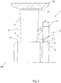
- an axial section shows the upper half of an (axial) fan 1 with a fan wheel 2 extending radially outwards about the axis of rotation RA of the fan 1 and a guide wheel 4 arranged in the axial direction of flow at a very small distance A from the fan wheel 2, where the distance A corresponds to a value of 0.02 of the fan wheel diameter Dv.
- the lower half, not shown, of the fan 1 is mirror-symmetrical.
- the fan wheel 2 has a plurality of fan blades 3 which are spaced apart from one another in the circumferential direction and which each extend radially outwards from the fan wheel hub 12 and thereby increase their axial width.
- Alternative fan blade shapes known from the art can also be used for all exemplary embodiments.
- the radially outer free end of the fan wheel blades 3 determines the outer circumference and consequently the fan wheel diameter Dv.
- a housing part 30 forming a flow channel is indicated, in which the fan 1 is inserted with a gap spacing 31 between the fan blades 3 and the inner wall of the housing part 30 .
- the housing part 30 can be an external component or integrated into the fan.
- the guide wheel 4 comprises a large number of air guide webs 5 running through the guide wheel in the axial direction and extends radially outwards from the guide wheel hub 13 to the outer peripheral ring 11.
- the maximum guide wheel diameter DI is less than the fan wheel diameter Dv. Since the guide wheel 4 and the fan wheel 2 are arranged so that they overlap in the direction of flow, the guide wheel 4 determines a partial cross-sectional area through which flow can flow of the cross-sectional area of the fan wheel through which flow can take place.
- the cross-sectional areas that can be flowed through are formed by the blade section 8 extending radially outwards from the fan wheel hub 12 and the guide section 9 extending radially outwards from the stator hub 13, the diameter ratio of the guide section 9 to the blade section 8 being 0.4 in the embodiment shown.
- the radially outer part of the blade section 8 is not covered by the guide wheel 4, so that the flow generated by the fan wheel 2 partly first passes through the guide wheel 4, partly directly to the outside axially.
- the outer circumferential ring 11 runs parallel to the axis of rotation RA essentially over the entire width B of the guide wheel 4 and is designed as a thin-walled circumferential ring, the thickness of which corresponds to a value of 0.01 of the fan wheel diameter Dv.
- the width B of the guide wheel 4 corresponds to a value of 0.065 of the fan wheel diameter Dv.
- the fan wheel hub 12 and the guide wheel hub 13 have the same hub diameter Dn.
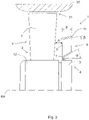
- the execution according to 2 is to the one in figure 1 Identical except for the design of the idler wheel, so that to avoid repetitions on the figure 1 described features reference is made.
- the guide wheel 4 according to the embodiment figure 3 additionally comprises an inner ring 7 which has a section set at an angle ⁇ of 40° relative to the axis of rotation RA and runs obliquely radially outwards in the axial direction of flow over the entire width B of the guide wheel 4 .
- the inner ring 7 has a V-shaped cross section with a leg engaging on the stator hub 13 and a leg forming the offset section. The inner ring 7 effectively prevents an axial backflow of air in the direction of the fan wheel 2 in the radially inner area adjoining the hubs 12, 13.
- the execution according to 3 is identical to that in figure 2 until, that the outer peripheral ring 11 is modified.
- the guide wheel 4 thus forms, through the inner ring 7 and the outer peripheral ring 11, a nozzle with a flow cross section that decreases in the direction of flow. Due to the inclined position of the outer peripheral ring 11, the maximum guide wheel cross section increases by the length of the opposite side of the angle ⁇ .
- figure 4 is a diagram with characteristic curves for the pressure profile psf [Pa] and the efficiency nse [%] at different volume flows qv [m 3 /h] of the fan 1 according to 1 and the same fan shown without guide wheel 4, the solid curves each according to the fan 1 figure 1 and the dashed characteristic curves each identify the fan without diffuser.
- the advantageous effect with increased peak efficiency at a volume flow of approx. 1100 m 3 /h and higher pressure up to approx. 1300 m 3 /h, ie in the highly relevant operating range, can be clearly seen.
Landscapes
- Engineering & Computer Science (AREA)
- Mechanical Engineering (AREA)
- General Engineering & Computer Science (AREA)
- Physics & Mathematics (AREA)
- Geometry (AREA)
- Fluid Mechanics (AREA)
- Structures Of Non-Positive Displacement Pumps (AREA)
Claims (13)
- Ventilateur, comprenant une roue de ventilateur (2) présentant des pales de ventilateur (3), s'étendant radialement vers l'extérieur autour d'un axe de rotation du ventilateur (1) et dont la circonférence extérieure radiale détermine un diamètre de roue de ventilateur (Dv), et une roue directrice (4) pourvue de barrettes de guidage d'air (5), disposée dans la direction d'écoulement axiale à une distance (A) par rapport à la roue de ventilateur (1), qui s'étend radialement vers l'extérieur et présente un diamètre de roue directrice (DI) qui est inférieur au diamètre de roue de ventilateur (Dv) de sorte que la roue directrice (4) détermine une superficie de la section partielle d'une superficie de la section de roue de ventilateur,
caractérisé en ce que la roue directrice (4) présente dans une direction d'écoulement axiale une largeur (B) qui se situe dans une plage de 0,02 à 0,1 du diamètre de roue de ventilateur (Dv). - Ventilateur selon la revendication 1, caractérisé en ce que la roue de ventilateur (2) présente un moyeu de roue de ventilateur (12) et une partie de pale (8) consécutive au moyeu de roue de ventilateur (12) dans la direction radiale jusqu'à la circonférence extérieure de la roue de ventilateur (2), et la roue directrice (4) présente un moyeu de roue directrice (13) et une partie directrice (9) consécutive au moyeu de roue directrice (13) dans la direction radiale jusqu'à la circonférence extérieure de la roue directrice (4), un rapport de diamètre entre la partie directrice (9) et la partie de pale (8) étant situé dans une plage de 0,1 à 0,8.
- Ventilateur selon la revendication 2, caractérisé en ce que le rapport de diamètre entre la partie directrice (9) et la partie de pale (8) est situé dans une plage de 0,2 à 0,5.
- Ventilateur selon l'une quelconque des revendications précédentes, caractérisé en ce que la distance (A) dans la direction d'écoulement axiale entre la roue de ventilateur (2) et la roue directrice (4) est située dans une plage de 0,01 et 0,2, de préférence dans une plage de 0,01 et 0,05 du diamètre de roue de ventilateur (Dv).
- Ventilateur selon l'une quelconque des revendications précédentes, caractérisé en ce que la roue directrice (4) présente un anneau circonférentiel extérieur (11) sur sa circonférence extérieure radiale.
- Ventilateur selon la revendication précédente, caractérisé en ce que l'anneau circonférentiel extérieur (11) présente une épaisseur radiale qui correspond à 0,002 à 0,015 du diamètre de roue de ventilateur (Dv).
- Ventilateur selon l'une des deux revendications précédentes, caractérisé en ce que l'anneau circonférentiel extérieur (11) est réalisé de manière entièrement périphérique autour de la roue directrice (4) et présente en coupe axiale une section transversale non angulaire.
- Ventilateur selon l'une quelconque des revendications précédentes 5 à 7, caractérisé en ce que l'anneau circonférentiel extérieur (11) s'étend dans la direction d'écoulement axiale radialement vers l'extérieur en étant disposé selon un angle β de 5 à 25° par rapport à l'axe de rotation.
- Ventilateur selon l'une quelconque des revendications précédentes 5 à 8, caractérisé en ce que l'anneau circonférentiel extérieur (11) s'étend dans la direction d'écoulement axiale radialement vers l'extérieur en étant disposé selon un angle β de 5 à 10° par rapport à l'axe de rotation,
- Ventilateur selon l'une quelconque des revendications précédentes 2 à 9, caractérisé en ce que le moyeu de roue directrice (13) s'étend dans la direction d'écoulement axiale radialement vers l'extérieur en étant disposé selon un angle jusqu'à 60° par rapport à l'axe de rotation.
- Ventilateur selon l'une quelconque des revendications précédentes 2 à 9, caractérisé en ce que la roue directrice (4) présente dans la direction radiale de manière adjacente au moyeu de roue directrice (13) un anneau intérieur (7) qui s'étend dans la direction d'écoulement axiale radialement vers l'extérieur en étant disposé selon un angle de 0 à 60° par rapport à l'axe de rotation sur toute la largeur (B) de la roue directrices (4).
- Ventilateur selon l'une quelconque des revendications précédentes 10 à 11, caractérisé en ce que l'angle est supérieur à l'angle β.
- Ventilateur selon l'une quelconque des revendications précédentes 5 à 12, caractérisé en ce que le moyeu de roue directrice (13) forme avec l'anneau circonférentiel extérieur (11) une buse ayant une section transversale de passage diminuant dans la direction d'écoulement.
Applications Claiming Priority (1)
| Application Number | Priority Date | Filing Date | Title |
|---|---|---|---|
| DE102016119916.8A DE102016119916A1 (de) | 2016-10-19 | 2016-10-19 | Ventilator mit Ventilatorrad und Leitrad |
Publications (3)
| Publication Number | Publication Date |
|---|---|
| EP3312427A1 EP3312427A1 (fr) | 2018-04-25 |
| EP3312427B1 true EP3312427B1 (fr) | 2022-08-17 |
| EP3312427B2 EP3312427B2 (fr) | 2025-10-01 |
Family
ID=59251473
Family Applications (1)
| Application Number | Title | Priority Date | Filing Date |
|---|---|---|---|
| EP17189145.0A Active EP3312427B2 (fr) | 2016-10-19 | 2017-09-04 | Ventilateur doté de la roue de ventilateur et des ailettes de diffusion |
Country Status (4)
| Country | Link |
|---|---|
| US (1) | US10428829B2 (fr) |
| EP (1) | EP3312427B2 (fr) |
| CN (1) | CN206309653U (fr) |
| DE (1) | DE102016119916A1 (fr) |
Families Citing this family (3)
| Publication number | Priority date | Publication date | Assignee | Title |
|---|---|---|---|---|
| DE102015205424A1 (de) * | 2015-03-25 | 2016-09-29 | Ebm-Papst Mulfingen Gmbh & Co. Kg | Nachleitrad |
| WO2017192647A1 (fr) * | 2016-05-03 | 2017-11-09 | Carrier Corporation | Entrée pour ventilateur axial |
| DE102018211808A1 (de) * | 2018-07-16 | 2020-01-16 | Ziehl-Abegg Se | Ventilator und Leiteinrichtung für einen Ventilator |
Citations (16)
| Publication number | Priority date | Publication date | Assignee | Title |
|---|---|---|---|---|
| CH219997A (de) | 1941-02-17 | 1942-03-15 | Ventilator A G | Ventilator. |
| GB766216A (en) | 1954-03-05 | 1957-01-16 | Stork Koninklijke Maschf | Improvements in and relating to pumps or fans provided with an axial flow impeller |
| US3536414A (en) | 1968-03-06 | 1970-10-27 | Gen Electric | Vanes for turning fluid flow in an annular duct |
| DE4404262A1 (de) | 1994-02-10 | 1995-08-17 | Guentner Gmbh Hans | Schutzgittervorrichtung für Ventilatoren, insbesondere von Luftkühlern |
| DE10330088A1 (de) | 2003-07-03 | 2005-02-03 | Asia Vital Components Co., Ltd. | Luftumlenkung bzw. Führung zur Beeinflussung der Windrichtung einer Wärmeabführung |
| US20050186070A1 (en) | 2004-02-23 | 2005-08-25 | Ling-Zhong Zeng | Fan assembly and method |
| US20060067816A1 (en) | 2004-09-24 | 2006-03-30 | Bor-Haw Chang | Cooling fan with fluid control device |
| EP1735568A2 (fr) | 2004-03-15 | 2006-12-27 | Airius, LLC | Dispositifs, systemes et procedes de deplacement d'air en colonne |
| US7478993B2 (en) | 2006-03-27 | 2009-01-20 | Valeo, Inc. | Cooling fan using Coanda effect to reduce recirculation |
| US7484925B2 (en) | 2005-05-10 | 2009-02-03 | Emp Advanced Development, Llc | Rotary axial fan assembly |
| EP1934484B1 (fr) | 2005-09-27 | 2009-03-04 | Continental Automotive GmbH | Module ventilateur |
| DE202011004708U1 (de) | 2010-08-12 | 2011-07-14 | Ziehl-Abegg Ag | Ventilator |
| WO2011151323A2 (fr) | 2010-06-01 | 2011-12-08 | Esg Mbh | Canal à surface de guidage d'écoulement |
| EP2541068A1 (fr) | 2011-06-29 | 2013-01-02 | ebm-papst Mulfingen GmbH & Co. KG | Ventilateur axial doté d'un corps de guidage d'écoulement |
| US20140086730A1 (en) | 2012-09-27 | 2014-03-27 | Delta Electronics, Inc. | Fan and pressure-increasing blade assembly thereof |
| DE102012109542A1 (de) | 2012-10-08 | 2014-04-10 | Ebm-Papst Mulfingen Gmbh & Co. Kg | "Strömungsgleichrichter für einen Axiallüfter" |
Family Cites Families (5)
| Publication number | Priority date | Publication date | Assignee | Title |
|---|---|---|---|---|
| DK345883D0 (da) * | 1983-07-28 | 1983-07-28 | Nordisk Ventilator | Aksialventilator |
| US6514052B2 (en) * | 2001-03-30 | 2003-02-04 | Emerson Electric Co. | Two sided radial fan for motor cooling |
| US6599088B2 (en) * | 2001-09-27 | 2003-07-29 | Borgwarner, Inc. | Dynamically sealing ring fan shroud assembly |
| JP5199849B2 (ja) * | 2008-12-05 | 2013-05-15 | 三菱重工業株式会社 | 車両用熱交換モジュールおよびこれを備えた車両 |
| US10330121B2 (en) * | 2015-02-26 | 2019-06-25 | Honeywell International Inc. | Systems and methods for axial compressor with secondary flow |
-
2016
- 2016-10-19 DE DE102016119916.8A patent/DE102016119916A1/de active Pending
- 2016-12-15 CN CN201621378057.6U patent/CN206309653U/zh active Active
-
2017
- 2017-09-04 EP EP17189145.0A patent/EP3312427B2/fr active Active
- 2017-10-18 US US15/786,842 patent/US10428829B2/en active Active
Patent Citations (16)
| Publication number | Priority date | Publication date | Assignee | Title |
|---|---|---|---|---|
| CH219997A (de) | 1941-02-17 | 1942-03-15 | Ventilator A G | Ventilator. |
| GB766216A (en) | 1954-03-05 | 1957-01-16 | Stork Koninklijke Maschf | Improvements in and relating to pumps or fans provided with an axial flow impeller |
| US3536414A (en) | 1968-03-06 | 1970-10-27 | Gen Electric | Vanes for turning fluid flow in an annular duct |
| DE4404262A1 (de) | 1994-02-10 | 1995-08-17 | Guentner Gmbh Hans | Schutzgittervorrichtung für Ventilatoren, insbesondere von Luftkühlern |
| DE10330088A1 (de) | 2003-07-03 | 2005-02-03 | Asia Vital Components Co., Ltd. | Luftumlenkung bzw. Führung zur Beeinflussung der Windrichtung einer Wärmeabführung |
| US20050186070A1 (en) | 2004-02-23 | 2005-08-25 | Ling-Zhong Zeng | Fan assembly and method |
| EP1735568A2 (fr) | 2004-03-15 | 2006-12-27 | Airius, LLC | Dispositifs, systemes et procedes de deplacement d'air en colonne |
| US20060067816A1 (en) | 2004-09-24 | 2006-03-30 | Bor-Haw Chang | Cooling fan with fluid control device |
| US7484925B2 (en) | 2005-05-10 | 2009-02-03 | Emp Advanced Development, Llc | Rotary axial fan assembly |
| EP1934484B1 (fr) | 2005-09-27 | 2009-03-04 | Continental Automotive GmbH | Module ventilateur |
| US7478993B2 (en) | 2006-03-27 | 2009-01-20 | Valeo, Inc. | Cooling fan using Coanda effect to reduce recirculation |
| WO2011151323A2 (fr) | 2010-06-01 | 2011-12-08 | Esg Mbh | Canal à surface de guidage d'écoulement |
| DE202011004708U1 (de) | 2010-08-12 | 2011-07-14 | Ziehl-Abegg Ag | Ventilator |
| EP2541068A1 (fr) | 2011-06-29 | 2013-01-02 | ebm-papst Mulfingen GmbH & Co. KG | Ventilateur axial doté d'un corps de guidage d'écoulement |
| US20140086730A1 (en) | 2012-09-27 | 2014-03-27 | Delta Electronics, Inc. | Fan and pressure-increasing blade assembly thereof |
| DE102012109542A1 (de) | 2012-10-08 | 2014-04-10 | Ebm-Papst Mulfingen Gmbh & Co. Kg | "Strömungsgleichrichter für einen Axiallüfter" |
Also Published As
| Publication number | Publication date |
|---|---|
| EP3312427A1 (fr) | 2018-04-25 |
| US10428829B2 (en) | 2019-10-01 |
| EP3312427B2 (fr) | 2025-10-01 |
| CN206309653U (zh) | 2017-07-07 |
| DE102016119916A1 (de) | 2018-04-19 |
| US20180106267A1 (en) | 2018-04-19 |
Similar Documents
| Publication | Publication Date | Title |
|---|---|---|
| DE102011121996B4 (de) | Vorrichtung zum Betrieb eines Verdichters | |
| EP3702620B1 (fr) | Ventilateur axial pourvu d'aubes de roue de ventilateur réduisant le bruit et pourvues de trous | |
| DE202004010088U1 (de) | Laufrad, insbesondere für einen Axialventilator | |
| WO2011038884A1 (fr) | Ventilateur diagonal | |
| WO2017017264A1 (fr) | Roue de ventilateur et module ventilateur de refroidissement | |
| EP3312427B1 (fr) | Ventilateur doté de la roue de ventilateur et des ailettes de diffusion | |
| DE102019120816B3 (de) | Verdichterlaufrad mit geteilten Hauptschaufeln | |
| EP3298284A1 (fr) | Grille de guidage d'écoulement plane | |
| EP3571416B1 (fr) | Rouet de ventilateur centrifuge caréné avec un flasque ayant une forme périodique et asymétrique | |
| EP3717783B1 (fr) | Dispositif de maintien pour un anémomètre et ventilateur radial | |
| DE112005003534T5 (de) | Flügelrad-Windkraft-Wandler | |
| EP2133574A2 (fr) | Grille de protection spatiale pour ventilateurs axiaux et procédé de fabrication de la grille de protection | |
| DE202016105863U1 (de) | Ventilator mit Ventilatorrad und Leitrad | |
| WO2015007443A1 (fr) | Rotor pour turbomachine thermique | |
| WO2015007512A1 (fr) | Rotor pour turbomachine thermique | |
| EP3399183B1 (fr) | Pale de rotor d'une éolienne | |
| DE102017118583B4 (de) | Anordnung von Stützstreben in einem abstromseitigen Ringraum einer Gasturbine | |
| DE102012015476A1 (de) | Stuktrierung der Oberfläche der Ogive eines Geschosses | |
| DE102019101277A1 (de) | Axiallüfteranordnung für Fahrzeuge | |
| DE212009000007U1 (de) | Radiallüfter | |
| DE1161481B (de) | Einrichtung zur Stabilisierung der Charakteristik von Kreiselradarbeitsmaschinen mit axialdurchstroemtem Laufrad | |
| DE102014118210B4 (de) | Mehrflutige Strömungsmaschine | |
| EP2811170A1 (fr) | Ventilateur radial | |
| DE202011002809U1 (de) | Statorelement sowie Hochvakuumpumpe | |
| EP3306100B1 (fr) | Buse d'entrée pour un ventilateur centrifuge |
Legal Events
| Date | Code | Title | Description |
|---|---|---|---|
| PUAI | Public reference made under article 153(3) epc to a published international application that has entered the european phase |
Free format text: ORIGINAL CODE: 0009012 |
|
| STAA | Information on the status of an ep patent application or granted ep patent |
Free format text: STATUS: THE APPLICATION HAS BEEN PUBLISHED |
|
| AK | Designated contracting states |
Kind code of ref document: A1 Designated state(s): AL AT BE BG CH CY CZ DE DK EE ES FI FR GB GR HR HU IE IS IT LI LT LU LV MC MK MT NL NO PL PT RO RS SE SI SK SM TR |
|
| AX | Request for extension of the european patent |
Extension state: BA ME |
|
| STAA | Information on the status of an ep patent application or granted ep patent |
Free format text: STATUS: REQUEST FOR EXAMINATION WAS MADE |
|
| 17P | Request for examination filed |
Effective date: 20180813 |
|
| RBV | Designated contracting states (corrected) |
Designated state(s): AL AT BE BG CH CY CZ DE DK EE ES FI FR GB GR HR HU IE IS IT LI LT LU LV MC MK MT NL NO PL PT RO RS SE SI SK SM TR |
|
| STAA | Information on the status of an ep patent application or granted ep patent |
Free format text: STATUS: EXAMINATION IS IN PROGRESS |
|
| 17Q | First examination report despatched |
Effective date: 20200331 |
|
| GRAP | Despatch of communication of intention to grant a patent |
Free format text: ORIGINAL CODE: EPIDOSNIGR1 |
|
| STAA | Information on the status of an ep patent application or granted ep patent |
Free format text: STATUS: GRANT OF PATENT IS INTENDED |
|
| INTG | Intention to grant announced |
Effective date: 20220406 |
|
| GRAS | Grant fee paid |
Free format text: ORIGINAL CODE: EPIDOSNIGR3 |
|
| GRAA | (expected) grant |
Free format text: ORIGINAL CODE: 0009210 |
|
| STAA | Information on the status of an ep patent application or granted ep patent |
Free format text: STATUS: THE PATENT HAS BEEN GRANTED |
|
| AK | Designated contracting states |
Kind code of ref document: B1 Designated state(s): AL AT BE BG CH CY CZ DE DK EE ES FI FR GB GR HR HU IE IS IT LI LT LU LV MC MK MT NL NO PL PT RO RS SE SI SK SM TR |
|
| REG | Reference to a national code |
Ref country code: CH Ref legal event code: EP |
|
| REG | Reference to a national code |
Ref country code: DE Ref legal event code: R096 Ref document number: 502017013620 Country of ref document: DE |
|
| REG | Reference to a national code |
Ref country code: IE Ref legal event code: FG4D Free format text: LANGUAGE OF EP DOCUMENT: GERMAN |
|
| REG | Reference to a national code |
Ref country code: AT Ref legal event code: REF Ref document number: 1512372 Country of ref document: AT Kind code of ref document: T Effective date: 20220915 |
|
| REG | Reference to a national code |
Ref country code: NL Ref legal event code: FP |
|
| REG | Reference to a national code |
Ref country code: LT Ref legal event code: MG9D |
|
| PG25 | Lapsed in a contracting state [announced via postgrant information from national office to epo] |
Ref country code: SE Free format text: LAPSE BECAUSE OF FAILURE TO SUBMIT A TRANSLATION OF THE DESCRIPTION OR TO PAY THE FEE WITHIN THE PRESCRIBED TIME-LIMIT Effective date: 20220817 Ref country code: RS Free format text: LAPSE BECAUSE OF FAILURE TO SUBMIT A TRANSLATION OF THE DESCRIPTION OR TO PAY THE FEE WITHIN THE PRESCRIBED TIME-LIMIT Effective date: 20220817 Ref country code: PT Free format text: LAPSE BECAUSE OF FAILURE TO SUBMIT A TRANSLATION OF THE DESCRIPTION OR TO PAY THE FEE WITHIN THE PRESCRIBED TIME-LIMIT Effective date: 20221219 Ref country code: NO Free format text: LAPSE BECAUSE OF FAILURE TO SUBMIT A TRANSLATION OF THE DESCRIPTION OR TO PAY THE FEE WITHIN THE PRESCRIBED TIME-LIMIT Effective date: 20221117 Ref country code: LV Free format text: LAPSE BECAUSE OF FAILURE TO SUBMIT A TRANSLATION OF THE DESCRIPTION OR TO PAY THE FEE WITHIN THE PRESCRIBED TIME-LIMIT Effective date: 20220817 Ref country code: LT Free format text: LAPSE BECAUSE OF FAILURE TO SUBMIT A TRANSLATION OF THE DESCRIPTION OR TO PAY THE FEE WITHIN THE PRESCRIBED TIME-LIMIT Effective date: 20220817 Ref country code: FI Free format text: LAPSE BECAUSE OF FAILURE TO SUBMIT A TRANSLATION OF THE DESCRIPTION OR TO PAY THE FEE WITHIN THE PRESCRIBED TIME-LIMIT Effective date: 20220817 |
|
| PG25 | Lapsed in a contracting state [announced via postgrant information from national office to epo] |
Ref country code: PL Free format text: LAPSE BECAUSE OF FAILURE TO SUBMIT A TRANSLATION OF THE DESCRIPTION OR TO PAY THE FEE WITHIN THE PRESCRIBED TIME-LIMIT Effective date: 20220817 Ref country code: IS Free format text: LAPSE BECAUSE OF FAILURE TO SUBMIT A TRANSLATION OF THE DESCRIPTION OR TO PAY THE FEE WITHIN THE PRESCRIBED TIME-LIMIT Effective date: 20221217 Ref country code: HR Free format text: LAPSE BECAUSE OF FAILURE TO SUBMIT A TRANSLATION OF THE DESCRIPTION OR TO PAY THE FEE WITHIN THE PRESCRIBED TIME-LIMIT Effective date: 20220817 Ref country code: GR Free format text: LAPSE BECAUSE OF FAILURE TO SUBMIT A TRANSLATION OF THE DESCRIPTION OR TO PAY THE FEE WITHIN THE PRESCRIBED TIME-LIMIT Effective date: 20221118 |
|
| PG25 | Lapsed in a contracting state [announced via postgrant information from national office to epo] |
Ref country code: SM Free format text: LAPSE BECAUSE OF FAILURE TO SUBMIT A TRANSLATION OF THE DESCRIPTION OR TO PAY THE FEE WITHIN THE PRESCRIBED TIME-LIMIT Effective date: 20220817 Ref country code: RO Free format text: LAPSE BECAUSE OF FAILURE TO SUBMIT A TRANSLATION OF THE DESCRIPTION OR TO PAY THE FEE WITHIN THE PRESCRIBED TIME-LIMIT Effective date: 20220817 Ref country code: ES Free format text: LAPSE BECAUSE OF FAILURE TO SUBMIT A TRANSLATION OF THE DESCRIPTION OR TO PAY THE FEE WITHIN THE PRESCRIBED TIME-LIMIT Effective date: 20220817 Ref country code: DK Free format text: LAPSE BECAUSE OF FAILURE TO SUBMIT A TRANSLATION OF THE DESCRIPTION OR TO PAY THE FEE WITHIN THE PRESCRIBED TIME-LIMIT Effective date: 20220817 Ref country code: CZ Free format text: LAPSE BECAUSE OF FAILURE TO SUBMIT A TRANSLATION OF THE DESCRIPTION OR TO PAY THE FEE WITHIN THE PRESCRIBED TIME-LIMIT Effective date: 20220817 |
|
| REG | Reference to a national code |
Ref country code: CH Ref legal event code: PL |
|
| REG | Reference to a national code |
Ref country code: DE Ref legal event code: R026 Ref document number: 502017013620 Country of ref document: DE |
|
| PLBI | Opposition filed |
Free format text: ORIGINAL CODE: 0009260 |
|
| REG | Reference to a national code |
Ref country code: BE Ref legal event code: MM Effective date: 20220930 |
|
| PG25 | Lapsed in a contracting state [announced via postgrant information from national office to epo] |
Ref country code: SK Free format text: LAPSE BECAUSE OF FAILURE TO SUBMIT A TRANSLATION OF THE DESCRIPTION OR TO PAY THE FEE WITHIN THE PRESCRIBED TIME-LIMIT Effective date: 20220817 Ref country code: MC Free format text: LAPSE BECAUSE OF FAILURE TO SUBMIT A TRANSLATION OF THE DESCRIPTION OR TO PAY THE FEE WITHIN THE PRESCRIBED TIME-LIMIT Effective date: 20220817 Ref country code: EE Free format text: LAPSE BECAUSE OF FAILURE TO SUBMIT A TRANSLATION OF THE DESCRIPTION OR TO PAY THE FEE WITHIN THE PRESCRIBED TIME-LIMIT Effective date: 20220817 |
|
| PLAX | Notice of opposition and request to file observation + time limit sent |
Free format text: ORIGINAL CODE: EPIDOSNOBS2 |
|
| 26 | Opposition filed |
Opponent name: ZIEHL-ABEGG SE Effective date: 20230515 |
|
| P01 | Opt-out of the competence of the unified patent court (upc) registered |
Effective date: 20230522 |
|
| PG25 | Lapsed in a contracting state [announced via postgrant information from national office to epo] |
Ref country code: LU Free format text: LAPSE BECAUSE OF NON-PAYMENT OF DUE FEES Effective date: 20220904 Ref country code: AL Free format text: LAPSE BECAUSE OF FAILURE TO SUBMIT A TRANSLATION OF THE DESCRIPTION OR TO PAY THE FEE WITHIN THE PRESCRIBED TIME-LIMIT Effective date: 20220817 |
|
| PG25 | Lapsed in a contracting state [announced via postgrant information from national office to epo] |
Ref country code: LI Free format text: LAPSE BECAUSE OF NON-PAYMENT OF DUE FEES Effective date: 20220930 Ref country code: IE Free format text: LAPSE BECAUSE OF NON-PAYMENT OF DUE FEES Effective date: 20220904 Ref country code: CH Free format text: LAPSE BECAUSE OF NON-PAYMENT OF DUE FEES Effective date: 20220930 |
|
| PG25 | Lapsed in a contracting state [announced via postgrant information from national office to epo] |
Ref country code: SI Free format text: LAPSE BECAUSE OF FAILURE TO SUBMIT A TRANSLATION OF THE DESCRIPTION OR TO PAY THE FEE WITHIN THE PRESCRIBED TIME-LIMIT Effective date: 20220817 |
|
| PLBB | Reply of patent proprietor to notice(s) of opposition received |
Free format text: ORIGINAL CODE: EPIDOSNOBS3 |
|
| PG25 | Lapsed in a contracting state [announced via postgrant information from national office to epo] |
Ref country code: BE Free format text: LAPSE BECAUSE OF NON-PAYMENT OF DUE FEES Effective date: 20220930 |
|
| PG25 | Lapsed in a contracting state [announced via postgrant information from national office to epo] |
Ref country code: HU Free format text: LAPSE BECAUSE OF FAILURE TO SUBMIT A TRANSLATION OF THE DESCRIPTION OR TO PAY THE FEE WITHIN THE PRESCRIBED TIME-LIMIT; INVALID AB INITIO Effective date: 20170904 |
|
| PG25 | Lapsed in a contracting state [announced via postgrant information from national office to epo] |
Ref country code: CY Free format text: LAPSE BECAUSE OF FAILURE TO SUBMIT A TRANSLATION OF THE DESCRIPTION OR TO PAY THE FEE WITHIN THE PRESCRIBED TIME-LIMIT Effective date: 20220817 |
|
| PG25 | Lapsed in a contracting state [announced via postgrant information from national office to epo] |
Ref country code: MK Free format text: LAPSE BECAUSE OF FAILURE TO SUBMIT A TRANSLATION OF THE DESCRIPTION OR TO PAY THE FEE WITHIN THE PRESCRIBED TIME-LIMIT Effective date: 20220817 |
|
| PG25 | Lapsed in a contracting state [announced via postgrant information from national office to epo] |
Ref country code: TR Free format text: LAPSE BECAUSE OF FAILURE TO SUBMIT A TRANSLATION OF THE DESCRIPTION OR TO PAY THE FEE WITHIN THE PRESCRIBED TIME-LIMIT Effective date: 20220817 |
|
| PG25 | Lapsed in a contracting state [announced via postgrant information from national office to epo] |
Ref country code: BG Free format text: LAPSE BECAUSE OF FAILURE TO SUBMIT A TRANSLATION OF THE DESCRIPTION OR TO PAY THE FEE WITHIN THE PRESCRIBED TIME-LIMIT Effective date: 20220817 |
|
| PG25 | Lapsed in a contracting state [announced via postgrant information from national office to epo] |
Ref country code: MT Free format text: LAPSE BECAUSE OF FAILURE TO SUBMIT A TRANSLATION OF THE DESCRIPTION OR TO PAY THE FEE WITHIN THE PRESCRIBED TIME-LIMIT Effective date: 20220817 |
|
| APAH | Appeal reference modified |
Free format text: ORIGINAL CODE: EPIDOSCREFNO |
|
| APAW | Appeal reference deleted |
Free format text: ORIGINAL CODE: EPIDOSDREFNO |
|
| APAY | Date of receipt of notice of appeal deleted |
Free format text: ORIGINAL CODE: EPIDOSDNOA2O |
|
| APBP | Date of receipt of notice of appeal recorded |
Free format text: ORIGINAL CODE: EPIDOSNNOA2O |
|
| APBU | Appeal procedure closed |
Free format text: ORIGINAL CODE: EPIDOSNNOA9O |
|
| PUAH | Patent maintained in amended form |
Free format text: ORIGINAL CODE: 0009272 |
|
| STAA | Information on the status of an ep patent application or granted ep patent |
Free format text: STATUS: PATENT MAINTAINED AS AMENDED |
|
| 27A | Patent maintained in amended form |
Effective date: 20251001 |
|
| AK | Designated contracting states |
Kind code of ref document: B2 Designated state(s): AL AT BE BG CH CY CZ DE DK EE ES FI FR GB GR HR HU IE IS IT LI LT LU LV MC MK MT NL NO PL PT RO RS SE SI SK SM TR |
|
| REG | Reference to a national code |
Ref country code: DE Ref legal event code: R102 Ref document number: 502017013620 Country of ref document: DE |
|
| PGFP | Annual fee paid to national office [announced via postgrant information from national office to epo] |
Ref country code: DE Payment date: 20250919 Year of fee payment: 9 |
|
| PGFP | Annual fee paid to national office [announced via postgrant information from national office to epo] |
Ref country code: NL Payment date: 20250922 Year of fee payment: 9 |
|
| PGFP | Annual fee paid to national office [announced via postgrant information from national office to epo] |
Ref country code: GB Payment date: 20250923 Year of fee payment: 9 |
|
| PGFP | Annual fee paid to national office [announced via postgrant information from national office to epo] |
Ref country code: FR Payment date: 20250922 Year of fee payment: 9 Ref country code: AT Payment date: 20250918 Year of fee payment: 9 |
|
| REG | Reference to a national code |
Ref country code: NL Ref legal event code: FP |
|
| PGFP | Annual fee paid to national office [announced via postgrant information from national office to epo] |
Ref country code: IT Payment date: 20250930 Year of fee payment: 9 |