EP3312446A2 - Unité de synchronisation pour une boîte de vitesses ainsi que boîte de vitesses - Google Patents
Unité de synchronisation pour une boîte de vitesses ainsi que boîte de vitesses Download PDFInfo
- Publication number
- EP3312446A2 EP3312446A2 EP17196976.9A EP17196976A EP3312446A2 EP 3312446 A2 EP3312446 A2 EP 3312446A2 EP 17196976 A EP17196976 A EP 17196976A EP 3312446 A2 EP3312446 A2 EP 3312446A2
- Authority
- EP
- European Patent Office
- Prior art keywords
- spring
- hub
- ring
- unit according
- sliding sleeve
- Prior art date
- Legal status (The legal status is an assumption and is not a legal conclusion. Google has not performed a legal analysis and makes no representation as to the accuracy of the status listed.)
- Granted
Links
Images








Classifications
-
- F—MECHANICAL ENGINEERING; LIGHTING; HEATING; WEAPONS; BLASTING
- F16—ENGINEERING ELEMENTS AND UNITS; GENERAL MEASURES FOR PRODUCING AND MAINTAINING EFFECTIVE FUNCTIONING OF MACHINES OR INSTALLATIONS; THERMAL INSULATION IN GENERAL
- F16D—COUPLINGS FOR TRANSMITTING ROTATION; CLUTCHES; BRAKES
- F16D23/00—Details of mechanically-actuated clutches not specific for one distinct type
- F16D23/02—Arrangements for synchronisation, also for power-operated clutches
-
- F—MECHANICAL ENGINEERING; LIGHTING; HEATING; WEAPONS; BLASTING
- F16—ENGINEERING ELEMENTS AND UNITS; GENERAL MEASURES FOR PRODUCING AND MAINTAINING EFFECTIVE FUNCTIONING OF MACHINES OR INSTALLATIONS; THERMAL INSULATION IN GENERAL
- F16D—COUPLINGS FOR TRANSMITTING ROTATION; CLUTCHES; BRAKES
- F16D23/00—Details of mechanically-actuated clutches not specific for one distinct type
- F16D23/02—Arrangements for synchronisation, also for power-operated clutches
- F16D23/025—Synchro rings
-
- F—MECHANICAL ENGINEERING; LIGHTING; HEATING; WEAPONS; BLASTING
- F16—ENGINEERING ELEMENTS AND UNITS; GENERAL MEASURES FOR PRODUCING AND MAINTAINING EFFECTIVE FUNCTIONING OF MACHINES OR INSTALLATIONS; THERMAL INSULATION IN GENERAL
- F16H—GEARING
- F16H3/00—Toothed gearings for conveying rotary motion with variable gear ratio or for reversing rotary motion
- F16H3/02—Toothed gearings for conveying rotary motion with variable gear ratio or for reversing rotary motion without gears having orbital motion
- F16H3/08—Toothed gearings for conveying rotary motion with variable gear ratio or for reversing rotary motion without gears having orbital motion exclusively or essentially with continuously meshing gears, that can be disengaged from their shafts
- F16H3/083—Toothed gearings for conveying rotary motion with variable gear ratio or for reversing rotary motion without gears having orbital motion exclusively or essentially with continuously meshing gears, that can be disengaged from their shafts with radially acting and axially controlled clutching members, e.g. sliding keys
-
- F—MECHANICAL ENGINEERING; LIGHTING; HEATING; WEAPONS; BLASTING
- F16—ENGINEERING ELEMENTS AND UNITS; GENERAL MEASURES FOR PRODUCING AND MAINTAINING EFFECTIVE FUNCTIONING OF MACHINES OR INSTALLATIONS; THERMAL INSULATION IN GENERAL
- F16D—COUPLINGS FOR TRANSMITTING ROTATION; CLUTCHES; BRAKES
- F16D23/00—Details of mechanically-actuated clutches not specific for one distinct type
- F16D23/02—Arrangements for synchronisation, also for power-operated clutches
- F16D23/04—Arrangements for synchronisation, also for power-operated clutches with an additional friction clutch
- F16D23/06—Arrangements for synchronisation, also for power-operated clutches with an additional friction clutch and a blocking mechanism preventing the engagement of the main clutch prior to synchronisation
- F16D2023/0631—Sliding sleeves; Details thereof
-
- F—MECHANICAL ENGINEERING; LIGHTING; HEATING; WEAPONS; BLASTING
- F16—ENGINEERING ELEMENTS AND UNITS; GENERAL MEASURES FOR PRODUCING AND MAINTAINING EFFECTIVE FUNCTIONING OF MACHINES OR INSTALLATIONS; THERMAL INSULATION IN GENERAL
- F16D—COUPLINGS FOR TRANSMITTING ROTATION; CLUTCHES; BRAKES
- F16D23/00—Details of mechanically-actuated clutches not specific for one distinct type
- F16D23/02—Arrangements for synchronisation, also for power-operated clutches
- F16D23/04—Arrangements for synchronisation, also for power-operated clutches with an additional friction clutch
- F16D23/06—Arrangements for synchronisation, also for power-operated clutches with an additional friction clutch and a blocking mechanism preventing the engagement of the main clutch prior to synchronisation
- F16D2023/0637—Details relating to the hub member on which the sliding is arranged
-
- F—MECHANICAL ENGINEERING; LIGHTING; HEATING; WEAPONS; BLASTING
- F16—ENGINEERING ELEMENTS AND UNITS; GENERAL MEASURES FOR PRODUCING AND MAINTAINING EFFECTIVE FUNCTIONING OF MACHINES OR INSTALLATIONS; THERMAL INSULATION IN GENERAL
- F16D—COUPLINGS FOR TRANSMITTING ROTATION; CLUTCHES; BRAKES
- F16D23/00—Details of mechanically-actuated clutches not specific for one distinct type
- F16D23/02—Arrangements for synchronisation, also for power-operated clutches
- F16D23/04—Arrangements for synchronisation, also for power-operated clutches with an additional friction clutch
- F16D23/06—Arrangements for synchronisation, also for power-operated clutches with an additional friction clutch and a blocking mechanism preventing the engagement of the main clutch prior to synchronisation
Definitions
- the invention relates to a synchronization unit for a manual transmission of a motor vehicle and a manual transmission with such a synchronization unit.
- each gear is formed by two meshing gears.
- One of the gears is rotatably mounted on a transmission shaft, and the other gear is arranged as a so-called idler gear rotatably mounted on the second transmission shaft. With this gear shaft, the idler gear can then be rotatably connected when the appropriate gear is engaged.
- the synchronization unit serves to adjust the speed of the idler gear to the rotational speed of the gear shaft when engaging the gear, with which it is to be rotatably coupled.
- the synchronization process usually consists in that, when the sliding sleeve is moved out of a neutral position in order to shift a gear, first in a so-called presynchronization phase a synchronizer ring is acted upon by a friction surface assigned to it.
- the synchronizer ring rotates together with a hub on which the sliding sleeve is received, and the friction surface is rotatably connected to the gear to be switched.
- the friction torque ensures that the speed of the gear wheel is matched to the speed of the synchronizer ring and thus to the speed of the hub and also the transmission shaft.
- the sliding sleeve can be switched through, so that the gear wheel on the sliding sleeve and the hub is rotatably coupled to the transmission shaft.
- the object of the invention is to provide a synchronization unit, which is characterized by a very small installation space, especially in the axial direction.
- a synchronization unit for a manual transmission in particular a motor vehicle is provided according to the invention, with a hub which can be rotatably connected to a transmission shaft and a circumferentially continuous external toothing, a sliding sleeve which slidably on the outer toothing of the hub in the axial direction, but in the circumferential direction rotatably coupled, at least one synchronizer ring, which has a preferably conical friction surface for friction coupling of the synchronizer ring with a gear wheel of the gearbox and is actuated by the sliding sleeve, and a spring ring, which is arranged on one axial side of the outer toothing of the hub and arranged is to lock the sliding sleeve in a neutral position, wherein the spring ring rests against an end face of the sliding sleeve and is operatively disposed between the sliding sleeve and the synchronizer ring.
- the spring ring serves as an asynchronous element similar to plungers, which serve in known synchronization units to transmit an axial movement of the sliding sleeve on the synchronizer ring and to press this against its associated friction surface.
- the spring ring since the spring ring is located in the region of the end face of the sliding sleeve, it is possible to carry out the external toothing of the hub in the circumferential direction continuously. This increases the strength of the hub and the ability of the external teeth to be able to transmit a torque. Therefore, the hub can be made axially compact.
- front side of the sliding sleeve is understood here to mean a surface pointing in the axial direction. It does not necessarily have to be one of the surfaces that is outermost in the axial direction. It does not have to be a surface which is aligned perpendicular to the center axis of the sliding sleeve and thus to the central axis of one of the transmission shafts.
- the synchronization unit according to the invention can be used with a single synchronizer ring per gear wheel. If higher torques are to be transmitted during the synchronization, it is also possible to use multi-surface synchronizer ring assemblies, as are generally known from the prior art.
- the spring ring is a formed sheet metal ring. This makes it possible to realize the desired spring properties with very small dimensions in the axial direction. In particular, much smaller dimensions can be realized than is possible with a wire spring ring.
- the spring ring is preferably circumferentially interrupted so that it is resilient in the radial direction. In addition, this facilitates the assembly.
- the spring ring rests in the neutral position of the sliding sleeve on an internal toothing of the sliding sleeve, preferably on a Vorsynchronfase the internal toothing. In this way it is ensured that the spring ring does not interfere with the engagement between the sliding sleeve and the ratchet teeth of the synchronizer ring.
- the spring ring can serve as a synchronizing element similar to a pressure piece.
- the internal toothing of the sliding sleeve is circumferentially continuous. This also increases the ability to transmit torque from the hub to the sliding sleeve.
- the spring ring on a plurality of guide heels by means of which it is guided in the axial direction and in the circumferential direction of the hub.
- the guide heels which are formed for example as a circumferential, deformed guide collar or as axially extending guide plates, prevent the spring ring from undesirably expanding radially under the action of centrifugal forces.
- the spring ring comprises two or more substantially axially extending spring tabs provided in a hub provided in the hub Recess intervene.
- the spring tabs prevent the spring ring from undesirably twisting relative to the hub.
- the spring tabs may include a radially outwardly kinked or bent portion with which the spring ring can be coupled in the axial direction with the hub.
- the spring tab is preferably located on a spring-ring holding face of the hub, wherein the spring-holding face is preferably arranged on a radially outer side face of the recess and / or preferably runs obliquely with respect to an axial plane of the hub.
- the spring clip also serves to act on the spring ring in the axial direction in its initial position in which it rests against the end face of the hub.
- the spring retaining surface may be engaged behind in the axial direction of the spring tab, so that a good axial coupling is ensured.
- two spring rings are provided, which are arranged on mutually axially opposite sides of the hub. This results in a symmetrical structure in a synchronization unit, are synchronized with the two gear wheels.
- the spring rings can be arranged offset relative to each other so that they do not touch each other. There is therefore no reaction from the spring ring of one side of the spring ring of the other side.
- the spring tabs of the spring rings disposed on axially opposite sides abut each other radially in pairs.
- the assembly formed from the two spring washers is fixed together relative to the hub.
- the synchronizer ring is provided with index cams, which are radially within the outer contour are arranged. This ensures a completely closed in the circumferential direction toothing of the hub.
- the hub has at least one further recess for receiving the index cams, so that they are precisely guided in the circumferential direction relative to the hub.
- a synchronous assembly with a synchronizer ring and an additional synchronizer ring is provided, wherein the synchronizer ring is provided with at least one index cam having a recess in which a coupling extension is received, which is mounted on the additional synchronizer ring.
- the additional synchronizer ring is provided with at least one coupling cam, which engages in a pocket which is provided on the hub.
- a torque can be transmitted directly from the additional synchronizer ring in the hub without the synchronizer ring is acted upon. This can therefore rotate optimally in the blocking position in which it prevents a through-connection of the sliding sleeve.
- the recess in which engages the index cam, may be designed as a closed, pocket-like recess, so that the strength of the recess is increased.
- a transmission shaft 2 is shown, are arranged on the two gear wheels 3, 4 as idler gears. These can, in order to switch the corresponding gear, rotatably connected to the transmission shaft 2.
- the non-rotatable connection via a hub 10 which is rotatably mounted on the transmission shaft 2.
- the gear shaft 2 is provided with a gear shaft toothing 5, on which the hub 10 is rotatably mounted in the circumferential direction and axially fixed.
- the hub 10 On its inside, the hub 10 is provided with a hub toothing 12 which engages in the gear shaft toothing 5 of the gear shaft 2. On its outer side, the hub 10 is provided with external teeth 14.
- the external toothing 14 is continuous in the circumferential direction. "Continuously in the circumferential direction” here means that the external teeth 14 is not interrupted for receiving further components. It is harmless in this context, if one or the other tooth is possibly formed with a different geometry or completely eliminated. Decisive in terms of the ability to transmit a high torque, is the fact that the outer ring 14 bearing material ring is continuous below the root diameter of the toothing.
- a sliding sleeve 16 is arranged, which is provided on its outer side with a Wegnnut 18.
- the (not shown here) shift fork makes it possible to adjust the sliding sleeve 16 in the axial direction to switch the corresponding gear (based on the Figures 1 and 2 ie to the left to engage the gear with the gear 3, and to the right to engage the gear with the gear 4).
- the sliding sleeve 16 is provided on its inside with an internal toothing 20 or sliding sleeve toothing, which is adapted to the external toothing 14 of the hub 10 so that the sliding sleeve 16 is rotationally fixedly received on the hub 10 in the circumferential direction, but are displaced in the axial direction relative thereto can.
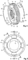
- a respective spring ring 22, 24 is arranged, which in detail in particular with reference to FIGS. 6 and 7 is explained.
- Each spring ring 22, 24 is made of sheet metal, in particular spring plate. These are stamped bent sheet metal parts.
- each spring ring 22, 24 is designed slotted, so interrupted in the circumferential direction.
- Each spring ring has a plurality of guide shoulders 26, with which it is guided in the axial direction and in the circumferential direction of the hub 10.
- Each spring ring 22, 24 is provided with a plurality of substantially axially extending guide plates 28, which together with the transition to the actual spring ring in each case form the guide shoulder 26.
- Each spring ring 22, 24 is also provided with a plurality of substantially axially extending spring tabs 30, 32. These extend through recesses 34 in the hub 10 (see also the FIGS. 8 and 9 ) and snap into each other.
- Each spring ring 22, 24 is provided with a longer spring tab 30 and a shorter spring tab 32, which are arranged opposite to each other.
- Each spring tab is slightly bent or bent radially (see the bending edges 36), so that the spring tabs 30, 32 elastically engage with each other when the spring rings 22, 24 are mounted on the hub 10.
- the outer diameter of the spring rings 22, 24 selected so that the maximum diameter of the spring rings 22, 24 in the assembled state between the root diameter and the tip circle diameter of the external teeth 14 of the hub 10 is located.
- this end face of the sliding sleeve is formed by a plurality of Vorsynchronfasen 40, which are remote from each other, outer sides of the individual teeth 42 of the internal teeth 20 of the sliding sleeve 16 are formed.
- the Vorsynchronfasen 40 are, relative to a radial plane, aligned obliquely, so that the radially further inward end of the Vorsynchronfasen closer to a median plane of the sliding sleeve 16 is located as the radially outer end.
- the spring rings 22, 24 are thus in the assembled state within the sliding sleeve 16 (ie closer to the center plane than the portions of the sliding sleeve, which define their length in the axial direction) and also on the axial end faces of the hub 10 (this is particularly in the Figures 1 and 2 to see).
- the sliding sleeve 16 is also provided with a plurality of stop teeth 44 (see in particular FIG. 10 ), in the region of each of the spring rings 22, 24 is provided with a recess 46 in the outer region. This results in a clearance for the stop teeth 44.
- the stop teeth 44 serve to limit the maximum axial switching path of the sliding sleeve 16.
- a multi-part synchronous module is provided here.
- This has the actual synchronizer ring 50, which is provided on the outside with a plurality of ratchet teeth 52, and an additional synchronizer ring 54.
- These are both rotationally fixedly coupled to the hub 10 in the circumferential direction, since they engage with multiple index cam 56 in recesses 34 in the hub 10th are provided (see also FIG. 1 ).
- an exception 57 is provided, in which engages a coupling extension 59 which is attached to the auxiliary synchronizer ring 54.
- the recesses 57 are designed here as unilaterally open recesses.
- a friction ring 60 is arranged, which is rotatably connected to a coupling ring 62 (see the index cam 63).
- the coupling ring 62 is rotatably connected to the gear 3 and has a friction surface 64. In this way, a per se known multi-surface synchronization assembly is formed.
- a single synchronizer ring 70 is arranged, which is also provided on the outside with ratchet teeth 52. On the inside, the synchronizer ring 70 cooperates with a friction surface 64, which is provided on a coupling ring 62, which is non-rotatably connected to the gear 4.
- the synchronizer ring 70 is also rotatably coupled to the hub 10.
- two index cams 72 are provided on the synchronizer ring. These extend through two diametrically opposite recesses 74 in the hub 10th
- the sliding sleeve 16 If one of the gears to be switched (for example, with the gear 4), the sliding sleeve 16, starting from their in the Figures 1 and 2 shown shifted position in the axial direction, so in this example to the right.
- the spring ring 24 can follow this movement, since its spring tabs 30, 32 slide on the spring tabs 32, 30 of the spring ring 22.
- the sliding sleeve When the gear is to be re-designed, the sliding sleeve, due to the friction between the outer periphery of the corresponding spring ring and the head surface of the teeth 42 of the internal teeth 20, takes the corresponding spring ring in the axial direction towards the hub 10 with, until the spring ring back to the hub is applied. As soon as the sliding sleeve is sufficiently far, the spring ring slides over the Vorsynchronfasen 40 to the outside, so that the spring ring has its original, expanded form again. The sliding sleeve 16 is now fixed again in its neutral position.
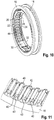
- FIGS. 12 to 16 a first embodiment shown.
- the same reference numerals are used, and reference is made to the above explanations in this respect.
- a multi-part synchronous module with a synchronizer ring 50 and an additional synchronizer ring 54 is used. Between these, the friction ring 60 is arranged.
- FIGS. 1 to 11 The difference between in the FIGS. 1 to 11 embodiment shown and the embodiment according to the FIGS. 12 to 16 is that in the embodiment of the additional synchronizer ring 54 a plurality of coupling cams 90 are provided. Accordingly, a plurality of pockets 92 are provided on the hub 10, in which the coupling cams 90 engage so that a torque between the hub 10 and the auxiliary synchronizer ring 54 can be transmitted.
- the synchronizing ring 50 transmits a portion of the friction torque between the hub 10 and the coupling ring 62.
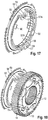
- FIGS. 17 to 20 a second embodiment is shown.
- the same reference numerals are used, and reference is made to the above explanations.
- each index cam 56 is not designed as recesses open on one side, but as closed pockets in which the corresponding index cam 56 engages.
- the closed, pocket-like contour of the recesses 57 is obtained by a web 57 A, which closes each recess 57 on the radially inner side. As a result, a higher strength is achieved.
- each spring ring 22, 24 do not attack each other in the assembled state, but that each spring ring 22, 24 is mounted independently of the other spring ring 24, 22 on the hub 10.
- each spring ring 22, 24 two spring tabs 31, which, viewed in cross section, have the shape of a very shallow V (see in particular FIG. 13 ).
- the concave inside of this "V" abuts against a spring ring retaining surface 90 which lies on the radially outer side of the recess 34, which is formed on the radially outer side of the recesses 74 of the hub 10.
Landscapes
- Engineering & Computer Science (AREA)
- General Engineering & Computer Science (AREA)
- Mechanical Engineering (AREA)
- Mechanical Operated Clutches (AREA)
Applications Claiming Priority (1)
| Application Number | Priority Date | Filing Date | Title |
|---|---|---|---|
| DE102016120007.7A DE102016120007A1 (de) | 2016-10-20 | 2016-10-20 | Synchronisierungseinheit für ein Schaltgetriebe sowie Schaltgetriebe |
Publications (3)
| Publication Number | Publication Date |
|---|---|
| EP3312446A2 true EP3312446A2 (fr) | 2018-04-25 |
| EP3312446A3 EP3312446A3 (fr) | 2018-06-13 |
| EP3312446B1 EP3312446B1 (fr) | 2020-12-16 |
Family
ID=60138263
Family Applications (1)
| Application Number | Title | Priority Date | Filing Date |
|---|---|---|---|
| EP17196976.9A Active EP3312446B1 (fr) | 2016-10-20 | 2017-10-18 | Unité de synchronisation pour une boîte de vitesses ainsi que boîte de vitesses |
Country Status (8)
| Country | Link |
|---|---|
| US (1) | US10851848B2 (fr) |
| EP (1) | EP3312446B1 (fr) |
| JP (1) | JP2018109442A (fr) |
| KR (1) | KR20180043746A (fr) |
| CN (1) | CN107965530B (fr) |
| BR (1) | BR102017022514A2 (fr) |
| DE (1) | DE102016120007A1 (fr) |
| ES (1) | ES2671868T3 (fr) |
Cited By (4)
| Publication number | Priority date | Publication date | Assignee | Title |
|---|---|---|---|---|
| EP3763961A1 (fr) * | 2019-07-12 | 2021-01-13 | HOERBIGER Antriebstechnik Holding GmbH | Unité de synchronisation pour une boîte de vitesses |
| CN112283261A (zh) * | 2020-10-09 | 2021-01-29 | 东风商用车有限公司 | 一种同步器优化方法及同步器 |
| CN112303142A (zh) * | 2020-10-29 | 2021-02-02 | 燕山大学 | 一种压力可控摩擦环式同步器 |
| WO2021254819A1 (fr) * | 2020-06-17 | 2021-12-23 | Punch Powertrain Psa E-Transmissions N.V. | Ensemble arbre intermédiaire perfectionné destiné à être utilisé dans une transmission de véhicule |
Families Citing this family (6)
| Publication number | Priority date | Publication date | Assignee | Title |
|---|---|---|---|---|
| CN209524062U (zh) * | 2019-01-29 | 2019-10-22 | 浙江春风动力股份有限公司 | 一种花键齿、齿轮接合机构及变速箱 |
| DE102019205538A1 (de) * | 2019-04-17 | 2020-10-22 | Zf Friedrichshafen Ag | Synchronring für eine Synchronisierungseinrichtung, insbesondere eine Synchronisierungseinrichtung für ein Kraftfahrzeug |
| DE102019113980A1 (de) * | 2019-05-24 | 2020-11-26 | Schaeffler Technologies AG & Co. KG | Druckstück und Synchronisierung mit einem Druckstück |
| WO2021083449A1 (fr) * | 2019-10-29 | 2021-05-06 | Schaeffler Technologies AG & Co. KG | Dispositif sélecteur pour système de conduite hybride d'un véhicule à moteur, système de conduite et véhicule à moteur |
| DE102021111062A1 (de) | 2021-04-29 | 2022-11-03 | Hoerbiger Antriebstechnik Holding Gmbh | Synchronisationsvorrichtung |
| DE102023128799A1 (de) * | 2023-10-19 | 2025-04-24 | Hoerbiger Antriebstechnik Holding Gmbh | Elektromagnetische Kupplung und Verfahren zum Betätigen einer elektromagnetischen Kupplung |
Family Cites Families (16)
| Publication number | Priority date | Publication date | Assignee | Title |
|---|---|---|---|---|
| US2488044A (en) * | 1945-11-07 | 1949-11-15 | Nash Kelvinator Corp | Blocker |
| US3631952A (en) * | 1969-06-21 | 1972-01-04 | Toyota Motor Co Ltd | Integral shifting key for a synchronizing transmission |
| DE2331053C2 (de) * | 1973-06-19 | 1983-07-14 | Autóipari Kutató Intézet, Budapest | Synchronisiereinrichtung für Wechselgetriebe insbesondere von Kraftfahrzeugen |
| DE3225201A1 (de) * | 1982-07-06 | 1984-01-12 | Volkswagenwerk Ag, 3180 Wolfsburg | Synchronisiereinrichtung |
| US4776228A (en) * | 1986-07-07 | 1988-10-11 | Chrysler Motors Corporation | Strutless synchronizer |
| JPH0538272Y2 (fr) * | 1986-07-21 | 1993-09-28 | ||
| US5105927A (en) * | 1991-01-16 | 1992-04-21 | New Venture Gear, Inc. | Single cone servo action synchronizer |
| US5620075B1 (en) * | 1995-07-28 | 1999-08-17 | Borg Warner Automotive | C-shaped synchronizer spring |
| JP3748749B2 (ja) | 1999-11-01 | 2006-02-22 | 本田技研工業株式会社 | トランスミッションの同期結合装置 |
| DE102005056827A1 (de) | 2005-11-22 | 2007-05-31 | Getrag Synchrontechnik Gmbh | Synchronring und Synchronkupplung |
| DE102006023098B3 (de) * | 2006-05-16 | 2007-08-30 | Getrag Ford Transmissions Gmbh | Mehrfach-Synchronisiereinheit für ein Schaltgetriebe |
| DE102008054665A1 (de) | 2008-12-15 | 2010-06-17 | Zf Friedrichshafen Ag | Schaltanordnung zum Schalten des Rückwärtsganges eines Zahnräderwechselgetriebes und Zahnräderwechselgetriebe |
| CN203879958U (zh) | 2014-04-15 | 2014-10-15 | 浙江万里扬变速器股份有限公司 | 一种副箱用锁环式汽车同步器 |
| CN104265793A (zh) | 2014-09-19 | 2015-01-07 | 浙江万里扬变速器股份有限公司 | 一种短行程双锥面锁环式同步器 |
| DE102015100869B4 (de) * | 2015-01-21 | 2016-10-13 | Hoerbiger Antriebstechnik Holding Gmbh | Verfahren zur Herstellung eines Synchronrings sowie Synchronring für synchronisierte Schaltgetriebe |
| FR3033856A1 (fr) * | 2015-03-16 | 2016-09-23 | Peugeot Citroen Automobiles Sa | Dispositif de synchronisation de boite de vitesses |
-
2016
- 2016-10-20 DE DE102016120007.7A patent/DE102016120007A1/de not_active Ceased
-
2017
- 2017-10-18 ES ES17196976T patent/ES2671868T3/es active Active
- 2017-10-18 EP EP17196976.9A patent/EP3312446B1/fr active Active
- 2017-10-19 BR BR102017022514-3A patent/BR102017022514A2/pt not_active Application Discontinuation
- 2017-10-19 KR KR1020170135828A patent/KR20180043746A/ko not_active Withdrawn
- 2017-10-20 US US15/788,849 patent/US10851848B2/en not_active Expired - Fee Related
- 2017-10-20 JP JP2017203097A patent/JP2018109442A/ja active Pending
- 2017-10-20 CN CN201710984942.1A patent/CN107965530B/zh active Active
Cited By (6)
| Publication number | Priority date | Publication date | Assignee | Title |
|---|---|---|---|---|
| EP3763961A1 (fr) * | 2019-07-12 | 2021-01-13 | HOERBIGER Antriebstechnik Holding GmbH | Unité de synchronisation pour une boîte de vitesses |
| WO2021254819A1 (fr) * | 2020-06-17 | 2021-12-23 | Punch Powertrain Psa E-Transmissions N.V. | Ensemble arbre intermédiaire perfectionné destiné à être utilisé dans une transmission de véhicule |
| NL2025845B1 (en) * | 2020-06-17 | 2022-02-17 | Punch Powertrain Psa E Trans N V | Improved lay-shaft assembly for use in a vehicle transmission |
| US12158205B2 (en) | 2020-06-17 | 2024-12-03 | Punch Powertrain Psa E-Transmissions N.V. | Lay-shaft assembly for use in a vehicle transmission |
| CN112283261A (zh) * | 2020-10-09 | 2021-01-29 | 东风商用车有限公司 | 一种同步器优化方法及同步器 |
| CN112303142A (zh) * | 2020-10-29 | 2021-02-02 | 燕山大学 | 一种压力可控摩擦环式同步器 |
Also Published As
| Publication number | Publication date |
|---|---|
| EP3312446A3 (fr) | 2018-06-13 |
| CN107965530A (zh) | 2018-04-27 |
| US10851848B2 (en) | 2020-12-01 |
| DE102016120007A1 (de) | 2018-04-26 |
| EP3312446B1 (fr) | 2020-12-16 |
| JP2018109442A (ja) | 2018-07-12 |
| US20180112721A1 (en) | 2018-04-26 |
| KR20180043746A (ko) | 2018-04-30 |
| ES2671868T1 (es) | 2018-06-11 |
| BR102017022514A2 (pt) | 2018-05-29 |
| CN107965530B (zh) | 2021-02-09 |
| ES2671868T3 (es) | 2021-10-01 |
Similar Documents
| Publication | Publication Date | Title |
|---|---|---|
| EP3312446B1 (fr) | Unité de synchronisation pour une boîte de vitesses ainsi que boîte de vitesses | |
| DE102010036278B4 (de) | Transmitter mit vormontierten Synchronringen | |
| EP2235391B1 (fr) | Élément amplificateur de force | |
| EP3472484B1 (fr) | Dispositif de synchronisation pour une boîte de vitesses manuelle | |
| EP2677188B1 (fr) | Anneau de synchronisation | |
| DE102016104495A1 (de) | Schiebemuffe einer Synchronisationsvorrichtung für ein Schaltgetriebe sowie Verfahren zum Herstellen einer solchen Schiebemuffe | |
| DE102010016715A1 (de) | Getriebe-Synchronisationsvorrichtung | |
| WO2007059868A1 (fr) | Bague de synchronisation et accouplement de synchronisation | |
| DE102015102141B4 (de) | Transmitter für ein Schaltgetriebe für ein Kraftfahrzeug, Baugruppe mit Transmitter, Getriebewelle und Gangrad sowie Getriebe | |
| DE102013209638A1 (de) | Synchronisiereinheit | |
| DE102012001836B4 (de) | Schalttransmitter eines sperrsynchronisierten Schaltgetriebes | |
| DE19581869B4 (de) | Planetengetriebe | |
| DE102006060535A1 (de) | Synchronisiereinrichtung für ein Schaltgetriebe | |
| DE102012209219A1 (de) | Synchronkörper | |
| DE925443C (de) | Synchronisiereinrichtung | |
| WO2018072790A2 (fr) | Dispositif et procédé de synchronisation | |
| DE102017113908A1 (de) | Klauenkupplungsvorrichtung | |
| DE102015113614B4 (de) | Synchronring eines Schaltgetriebes sowie Schaltgetriebe mit einem solchen Synchronring | |
| DE102010036281B4 (de) | Transmitter für ein Schaltgetriebe für ein Kraftfahrzeug | |
| DE102010036282B4 (de) | Transmitter für eine Synchronisierungsbaugruppe eines Schaltgetriebes | |
| EP3835609B1 (fr) | Dispositif de synchronisation | |
| DE102012209214A1 (de) | Synchronisiereinheit | |
| DE102008019247A1 (de) | Gangrad eines Schaltgetriebes | |
| WO2018072786A2 (fr) | Dispositif et procédé permettant de synchroniser un arbre de transmission et deux pignons fous | |
| DE102021108283A1 (de) | Synchronisationsvorrichtung |
Legal Events
| Date | Code | Title | Description |
|---|---|---|---|
| PUAI | Public reference made under article 153(3) epc to a published international application that has entered the european phase |
Free format text: ORIGINAL CODE: 0009012 |
|
| STAA | Information on the status of an ep patent application or granted ep patent |
Free format text: STATUS: THE APPLICATION HAS BEEN PUBLISHED |
|
| AK | Designated contracting states |
Kind code of ref document: A2 Designated state(s): AL AT BE BG CH CY CZ DE DK EE ES FI FR GB GR HR HU IE IS IT LI LT LU LV MC MK MT NL NO PL PT RO RS SE SI SK SM TR |
|
| AX | Request for extension of the european patent |
Extension state: BA ME |
|
| PUAL | Search report despatched |
Free format text: ORIGINAL CODE: 0009013 |
|
| REG | Reference to a national code |
Ref country code: ES Ref legal event code: BA2A Ref document number: 2671868 Country of ref document: ES Kind code of ref document: T1 Effective date: 20180611 |
|
| AK | Designated contracting states |
Kind code of ref document: A3 Designated state(s): AL AT BE BG CH CY CZ DE DK EE ES FI FR GB GR HR HU IE IS IT LI LT LU LV MC MK MT NL NO PL PT RO RS SE SI SK SM TR |
|
| AX | Request for extension of the european patent |
Extension state: BA ME |
|
| RIC1 | Information provided on ipc code assigned before grant |
Ipc: F16D 23/06 20060101AFI20180508BHEP Ipc: F16D 23/02 20060101ALI20180508BHEP |
|
| REG | Reference to a national code |
Ref country code: FR Ref legal event code: EL |
|
| STAA | Information on the status of an ep patent application or granted ep patent |
Free format text: STATUS: REQUEST FOR EXAMINATION WAS MADE |
|
| 17P | Request for examination filed |
Effective date: 20181210 |
|
| RBV | Designated contracting states (corrected) |
Designated state(s): AL AT BE BG CH CY CZ DE DK EE ES FI FR GB GR HR HU IE IS IT LI LT LU LV MC MK MT NL NO PL PT RO RS SE SI SK SM TR |
|
| GRAP | Despatch of communication of intention to grant a patent |
Free format text: ORIGINAL CODE: EPIDOSNIGR1 |
|
| STAA | Information on the status of an ep patent application or granted ep patent |
Free format text: STATUS: GRANT OF PATENT IS INTENDED |
|
| INTG | Intention to grant announced |
Effective date: 20200625 |
|
| GRAS | Grant fee paid |
Free format text: ORIGINAL CODE: EPIDOSNIGR3 |
|
| GRAA | (expected) grant |
Free format text: ORIGINAL CODE: 0009210 |
|
| STAA | Information on the status of an ep patent application or granted ep patent |
Free format text: STATUS: THE PATENT HAS BEEN GRANTED |
|
| AK | Designated contracting states |
Kind code of ref document: B1 Designated state(s): AL AT BE BG CH CY CZ DE DK EE ES FI FR GB GR HR HU IE IS IT LI LT LU LV MC MK MT NL NO PL PT RO RS SE SI SK SM TR |
|
| REG | Reference to a national code |
Ref country code: GB Ref legal event code: FG4D Free format text: NOT ENGLISH |
|
| REG | Reference to a national code |
Ref country code: IE Ref legal event code: FG4D Free format text: LANGUAGE OF EP DOCUMENT: GERMAN |
|
| REG | Reference to a national code |
Ref country code: DE Ref legal event code: R096 Ref document number: 502017008676 Country of ref document: DE |
|
| REG | Reference to a national code |
Ref country code: AT Ref legal event code: REF Ref document number: 1345871 Country of ref document: AT Kind code of ref document: T Effective date: 20210115 |
|
| PG25 | Lapsed in a contracting state [announced via postgrant information from national office to epo] |
Ref country code: NO Free format text: LAPSE BECAUSE OF FAILURE TO SUBMIT A TRANSLATION OF THE DESCRIPTION OR TO PAY THE FEE WITHIN THE PRESCRIBED TIME-LIMIT Effective date: 20210316 Ref country code: RS Free format text: LAPSE BECAUSE OF FAILURE TO SUBMIT A TRANSLATION OF THE DESCRIPTION OR TO PAY THE FEE WITHIN THE PRESCRIBED TIME-LIMIT Effective date: 20201216 Ref country code: GR Free format text: LAPSE BECAUSE OF FAILURE TO SUBMIT A TRANSLATION OF THE DESCRIPTION OR TO PAY THE FEE WITHIN THE PRESCRIBED TIME-LIMIT Effective date: 20210317 Ref country code: FI Free format text: LAPSE BECAUSE OF FAILURE TO SUBMIT A TRANSLATION OF THE DESCRIPTION OR TO PAY THE FEE WITHIN THE PRESCRIBED TIME-LIMIT Effective date: 20201216 |
|
| REG | Reference to a national code |
Ref country code: NL Ref legal event code: MP Effective date: 20201216 |
|
| PG25 | Lapsed in a contracting state [announced via postgrant information from national office to epo] |
Ref country code: BG Free format text: LAPSE BECAUSE OF FAILURE TO SUBMIT A TRANSLATION OF THE DESCRIPTION OR TO PAY THE FEE WITHIN THE PRESCRIBED TIME-LIMIT Effective date: 20210316 Ref country code: LV Free format text: LAPSE BECAUSE OF FAILURE TO SUBMIT A TRANSLATION OF THE DESCRIPTION OR TO PAY THE FEE WITHIN THE PRESCRIBED TIME-LIMIT Effective date: 20201216 Ref country code: SE Free format text: LAPSE BECAUSE OF FAILURE TO SUBMIT A TRANSLATION OF THE DESCRIPTION OR TO PAY THE FEE WITHIN THE PRESCRIBED TIME-LIMIT Effective date: 20201216 |
|
| PG25 | Lapsed in a contracting state [announced via postgrant information from national office to epo] |
Ref country code: NL Free format text: LAPSE BECAUSE OF FAILURE TO SUBMIT A TRANSLATION OF THE DESCRIPTION OR TO PAY THE FEE WITHIN THE PRESCRIBED TIME-LIMIT Effective date: 20201216 Ref country code: HR Free format text: LAPSE BECAUSE OF FAILURE TO SUBMIT A TRANSLATION OF THE DESCRIPTION OR TO PAY THE FEE WITHIN THE PRESCRIBED TIME-LIMIT Effective date: 20201216 |
|
| REG | Reference to a national code |
Ref country code: LT Ref legal event code: MG9D |
|
| PG25 | Lapsed in a contracting state [announced via postgrant information from national office to epo] |
Ref country code: SK Free format text: LAPSE BECAUSE OF FAILURE TO SUBMIT A TRANSLATION OF THE DESCRIPTION OR TO PAY THE FEE WITHIN THE PRESCRIBED TIME-LIMIT Effective date: 20201216 Ref country code: PT Free format text: LAPSE BECAUSE OF FAILURE TO SUBMIT A TRANSLATION OF THE DESCRIPTION OR TO PAY THE FEE WITHIN THE PRESCRIBED TIME-LIMIT Effective date: 20210416 Ref country code: RO Free format text: LAPSE BECAUSE OF FAILURE TO SUBMIT A TRANSLATION OF THE DESCRIPTION OR TO PAY THE FEE WITHIN THE PRESCRIBED TIME-LIMIT Effective date: 20201216 Ref country code: SM Free format text: LAPSE BECAUSE OF FAILURE TO SUBMIT A TRANSLATION OF THE DESCRIPTION OR TO PAY THE FEE WITHIN THE PRESCRIBED TIME-LIMIT Effective date: 20201216 Ref country code: EE Free format text: LAPSE BECAUSE OF FAILURE TO SUBMIT A TRANSLATION OF THE DESCRIPTION OR TO PAY THE FEE WITHIN THE PRESCRIBED TIME-LIMIT Effective date: 20201216 Ref country code: CZ Free format text: LAPSE BECAUSE OF FAILURE TO SUBMIT A TRANSLATION OF THE DESCRIPTION OR TO PAY THE FEE WITHIN THE PRESCRIBED TIME-LIMIT Effective date: 20201216 Ref country code: LT Free format text: LAPSE BECAUSE OF FAILURE TO SUBMIT A TRANSLATION OF THE DESCRIPTION OR TO PAY THE FEE WITHIN THE PRESCRIBED TIME-LIMIT Effective date: 20201216 |
|
| PG25 | Lapsed in a contracting state [announced via postgrant information from national office to epo] |
Ref country code: PL Free format text: LAPSE BECAUSE OF FAILURE TO SUBMIT A TRANSLATION OF THE DESCRIPTION OR TO PAY THE FEE WITHIN THE PRESCRIBED TIME-LIMIT Effective date: 20201216 |
|
| REG | Reference to a national code |
Ref country code: DE Ref legal event code: R097 Ref document number: 502017008676 Country of ref document: DE |
|
| PG25 | Lapsed in a contracting state [announced via postgrant information from national office to epo] |
Ref country code: IS Free format text: LAPSE BECAUSE OF FAILURE TO SUBMIT A TRANSLATION OF THE DESCRIPTION OR TO PAY THE FEE WITHIN THE PRESCRIBED TIME-LIMIT Effective date: 20210416 |
|
| REG | Reference to a national code |
Ref country code: ES Ref legal event code: FG2A Ref document number: 2671868 Country of ref document: ES Kind code of ref document: T3 Effective date: 20211001 |
|
| PLBE | No opposition filed within time limit |
Free format text: ORIGINAL CODE: 0009261 |
|
| STAA | Information on the status of an ep patent application or granted ep patent |
Free format text: STATUS: NO OPPOSITION FILED WITHIN TIME LIMIT |
|
| PG25 | Lapsed in a contracting state [announced via postgrant information from national office to epo] |
Ref country code: AL Free format text: LAPSE BECAUSE OF FAILURE TO SUBMIT A TRANSLATION OF THE DESCRIPTION OR TO PAY THE FEE WITHIN THE PRESCRIBED TIME-LIMIT Effective date: 20201216 |
|
| 26N | No opposition filed |
Effective date: 20210917 |
|
| PG25 | Lapsed in a contracting state [announced via postgrant information from national office to epo] |
Ref country code: DK Free format text: LAPSE BECAUSE OF FAILURE TO SUBMIT A TRANSLATION OF THE DESCRIPTION OR TO PAY THE FEE WITHIN THE PRESCRIBED TIME-LIMIT Effective date: 20201216 |
|
| PG25 | Lapsed in a contracting state [announced via postgrant information from national office to epo] |
Ref country code: SI Free format text: LAPSE BECAUSE OF FAILURE TO SUBMIT A TRANSLATION OF THE DESCRIPTION OR TO PAY THE FEE WITHIN THE PRESCRIBED TIME-LIMIT Effective date: 20201216 |
|
| REG | Reference to a national code |
Ref country code: CH Ref legal event code: PL |
|
| PG25 | Lapsed in a contracting state [announced via postgrant information from national office to epo] |
Ref country code: IS Free format text: LAPSE BECAUSE OF FAILURE TO SUBMIT A TRANSLATION OF THE DESCRIPTION OR TO PAY THE FEE WITHIN THE PRESCRIBED TIME-LIMIT Effective date: 20210416 |
|
| REG | Reference to a national code |
Ref country code: BE Ref legal event code: MM Effective date: 20211031 |
|
| GBPC | Gb: european patent ceased through non-payment of renewal fee |
Effective date: 20211018 |
|
| PG25 | Lapsed in a contracting state [announced via postgrant information from national office to epo] |
Ref country code: MC Free format text: LAPSE BECAUSE OF FAILURE TO SUBMIT A TRANSLATION OF THE DESCRIPTION OR TO PAY THE FEE WITHIN THE PRESCRIBED TIME-LIMIT Effective date: 20201216 |
|
| PG25 | Lapsed in a contracting state [announced via postgrant information from national office to epo] |
Ref country code: LU Free format text: LAPSE BECAUSE OF NON-PAYMENT OF DUE FEES Effective date: 20211018 Ref country code: GB Free format text: LAPSE BECAUSE OF NON-PAYMENT OF DUE FEES Effective date: 20211018 Ref country code: BE Free format text: LAPSE BECAUSE OF NON-PAYMENT OF DUE FEES Effective date: 20211031 |
|
| PG25 | Lapsed in a contracting state [announced via postgrant information from national office to epo] |
Ref country code: LI Free format text: LAPSE BECAUSE OF NON-PAYMENT OF DUE FEES Effective date: 20211031 Ref country code: CH Free format text: LAPSE BECAUSE OF NON-PAYMENT OF DUE FEES Effective date: 20211031 |
|
| PG25 | Lapsed in a contracting state [announced via postgrant information from national office to epo] |
Ref country code: IE Free format text: LAPSE BECAUSE OF NON-PAYMENT OF DUE FEES Effective date: 20211018 |
|
| PGFP | Annual fee paid to national office [announced via postgrant information from national office to epo] |
Ref country code: FR Payment date: 20221024 Year of fee payment: 6 |
|
| PGFP | Annual fee paid to national office [announced via postgrant information from national office to epo] |
Ref country code: ES Payment date: 20221117 Year of fee payment: 6 |
|
| PG25 | Lapsed in a contracting state [announced via postgrant information from national office to epo] |
Ref country code: HU Free format text: LAPSE BECAUSE OF FAILURE TO SUBMIT A TRANSLATION OF THE DESCRIPTION OR TO PAY THE FEE WITHIN THE PRESCRIBED TIME-LIMIT; INVALID AB INITIO Effective date: 20171018 |
|
| PG25 | Lapsed in a contracting state [announced via postgrant information from national office to epo] |
Ref country code: CY Free format text: LAPSE BECAUSE OF FAILURE TO SUBMIT A TRANSLATION OF THE DESCRIPTION OR TO PAY THE FEE WITHIN THE PRESCRIBED TIME-LIMIT Effective date: 20201216 |
|
| REG | Reference to a national code |
Ref country code: AT Ref legal event code: MM01 Ref document number: 1345871 Country of ref document: AT Kind code of ref document: T Effective date: 20221018 |
|
| PG25 | Lapsed in a contracting state [announced via postgrant information from national office to epo] |
Ref country code: AT Free format text: LAPSE BECAUSE OF NON-PAYMENT OF DUE FEES Effective date: 20221018 |
|
| PG25 | Lapsed in a contracting state [announced via postgrant information from national office to epo] |
Ref country code: MK Free format text: LAPSE BECAUSE OF FAILURE TO SUBMIT A TRANSLATION OF THE DESCRIPTION OR TO PAY THE FEE WITHIN THE PRESCRIBED TIME-LIMIT Effective date: 20201216 |
|
| PG25 | Lapsed in a contracting state [announced via postgrant information from national office to epo] |
Ref country code: TR Free format text: LAPSE BECAUSE OF FAILURE TO SUBMIT A TRANSLATION OF THE DESCRIPTION OR TO PAY THE FEE WITHIN THE PRESCRIBED TIME-LIMIT Effective date: 20201216 |
|
| PG25 | Lapsed in a contracting state [announced via postgrant information from national office to epo] |
Ref country code: FR Free format text: LAPSE BECAUSE OF NON-PAYMENT OF DUE FEES Effective date: 20231031 |
|
| PG25 | Lapsed in a contracting state [announced via postgrant information from national office to epo] |
Ref country code: MT Free format text: LAPSE BECAUSE OF FAILURE TO SUBMIT A TRANSLATION OF THE DESCRIPTION OR TO PAY THE FEE WITHIN THE PRESCRIBED TIME-LIMIT Effective date: 20201216 |
|
| REG | Reference to a national code |
Ref country code: ES Ref legal event code: FD2A Effective date: 20241203 |
|
| PG25 | Lapsed in a contracting state [announced via postgrant information from national office to epo] |
Ref country code: ES Free format text: LAPSE BECAUSE OF NON-PAYMENT OF DUE FEES Effective date: 20231019 |
|
| PG25 | Lapsed in a contracting state [announced via postgrant information from national office to epo] |
Ref country code: ES Free format text: LAPSE BECAUSE OF NON-PAYMENT OF DUE FEES Effective date: 20231019 |
|
| PGFP | Annual fee paid to national office [announced via postgrant information from national office to epo] |
Ref country code: DE Payment date: 20251028 Year of fee payment: 9 |
|
| PGFP | Annual fee paid to national office [announced via postgrant information from national office to epo] |
Ref country code: IT Payment date: 20251024 Year of fee payment: 9 |