EP3312534A1 - Trocknungsvorrichtung - Google Patents
Trocknungsvorrichtung Download PDFInfo
- Publication number
- EP3312534A1 EP3312534A1 EP17197409.0A EP17197409A EP3312534A1 EP 3312534 A1 EP3312534 A1 EP 3312534A1 EP 17197409 A EP17197409 A EP 17197409A EP 3312534 A1 EP3312534 A1 EP 3312534A1
- Authority
- EP
- European Patent Office
- Prior art keywords
- drying
- chambers
- drying apparatus
- door
- rotating body
- Prior art date
- Legal status (The legal status is an assumption and is not a legal conclusion. Google has not performed a legal analysis and makes no representation as to the accuracy of the status listed.)
- Granted
Links
Images


Classifications
-
- F—MECHANICAL ENGINEERING; LIGHTING; HEATING; WEAPONS; BLASTING
- F26—DRYING
- F26B—DRYING SOLID MATERIALS OR OBJECTS BY REMOVING LIQUID THEREFROM
- F26B11/00—Machines or apparatus for drying solid materials or objects with movement which is non-progressive
- F26B11/18—Machines or apparatus for drying solid materials or objects with movement which is non-progressive on or in moving dishes, trays, pans, or other mainly-open receptacles
-
- F—MECHANICAL ENGINEERING; LIGHTING; HEATING; WEAPONS; BLASTING
- F26—DRYING
- F26B—DRYING SOLID MATERIALS OR OBJECTS BY REMOVING LIQUID THEREFROM
- F26B21/00—Arrangements for supplying or controlling air or other gases for drying solid materials or objects
- F26B21/30—Controlling, e.g. regulating, parameters of gas supply
- F26B21/37—Velocity of flow; Quantity of flow
-
- F—MECHANICAL ENGINEERING; LIGHTING; HEATING; WEAPONS; BLASTING
- F26—DRYING
- F26B—DRYING SOLID MATERIALS OR OBJECTS BY REMOVING LIQUID THEREFROM
- F26B25/00—Details of general application not covered by group F26B21/00 or F26B23/00
- F26B25/06—Chambers, containers, or receptacles
- F26B25/08—Parts thereof
- F26B25/12—Walls or sides; Doors
Definitions
- Embodiments described here concern an apparatus for drying objects for health-care, medical, or veterinary use, for example surgical instruments, laboratory instruments, endoscopes, garments, or suchlike.
- the drying apparatus can also be used for storing and preserving objects waiting to be picked up for use.
- objects are usually dried after at least one of the steps of washing, thermodisinfection and/or sterilization.
- the drying step is usually carried out using a drying apparatus or cabinet comprising at least one internal chamber selectively accessible by means of a sealed door.
- drying apparatuses are provided with a drying unit and possibly a filtering and sterilizing unit of the air sent into the chamber.
- the objects located inside the compartment are inserted and removed at a certain frequency and with numerous accesses by users.
- the internal chamber is divided into several spaces, in any case when the door is opened the whole chamber is affected and a separated treatment is not possible.
- one purpose of the present invention is to provide a drying apparatus which does not have any risk of contamination when an object is removed, or at least reduces said risk to a minimum.
- Another purpose of the present invention is to provide a drying apparatus which allows to organize the spaces in a manner consistent with the requirements for drying and removing certain types of objects.
- Another purpose of the invention is to provide a drying apparatus in which it is possible to deliver drying air, modulating the pressure thereof, depending on the different operating conditions of the drying apparatus, for example as a function of the fact that the drying apparatus, in certain steps of the process, is in communication with the outside environment or not, so as to further reduce any risk of contamination.
- Another purpose is to organize the drying volumes in accordance with specific drying requirements and possible connected treatment, as well as removal.
- the Applicant has devised, tested and embodied the present invention to overcome the shortcomings of the state of the art and to obtain these and other purposes and advantages.
- embodiments described here concern an apparatus for drying objects for health-care, medical, veterinary or similar use, comprising at least a drying unit configured to blow in drying air.
- the drying apparatus comprises:
- the chambers can be mobile either one on top of the other and/or one alongside the other.
- the chambers can be divided into compartments, each comprising its own door.
- the container can comprise at least an aperture with which the door is associated; at least a sealing element is positioned between the aperture and the door.
- the chambers can be separated from each other by at least an interspace made between the respective lateral walls.
- the drying apparatus comprises a single door through which to selectively access a specific one of the at least two chambers that are presented on each occasion with respect to the door.
- the drying apparatus can comprise two distinct doors respectively made to perform operations to load and remove the objects into/from the chambers.
- each chamber can comprise its own unit at least to control the drying cycle.
- the container comprises a rotating body in which the chambers are made, insulated from each other and configured to be selectively positioned in a desired position, for example in front of the user, for example for operations to load and remove the objects into/from the drying apparatus.
- the rotating body has a vertical axis of rotation.
- the rotating body has a horizontal axis of rotation.
- each chamber is equipped with means to correctly position an instrument so that it does not move or fall.
- the housing chambers are attached horizontally pivoting to the rotating body, which can have personalized sectors.
- the housing chambers are hinged to be able to oscillate in correspondence with their axis of rotation, which is eccentric with respect to the center of gravity and parallel to the axis of rotation of the rotating body.
- the housing chambers oscillating and/or horizontally pivoting have personalized access doors.
- the rotating body whether it has a vertical or horizontal axis, can be associated with a drive member to determine the rotation in a controlled and desired manner.
- each chamber can have means to personalize the treatment.
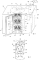
- Embodiments described here, using the attached drawings figs. 1-4 refer to a drying apparatus, or a drying cabinet, 10.
- the drying apparatus 10 can be used for drying objects such as surgical instruments, anesthesia tubes, endoscopes, or also clothing to be used for medical, health-care, or veterinary use.
- the drying apparatus 10 can also be used for storing and preserving the objects waiting to be removed by a user. In this way, objects do not risk being contaminated and can remain in a sterile atmosphere until they are actually used.
- the drying apparatus 10 comprises a drying unit 13 configured to blow in drying air.
- the drying apparatus 10 comprises a container 21 associated with the drying unit 13.
- the container 21 there are at least two chambers 11 which can be selectively opened by at least one specific door 12 associated with the container 21.
- the door 12 is able to open or close an aperture 24 accessing the chamber 11 facing toward the same.
- the at least two chambers 11 are configured mobile, to be selectively put in cooperation with the at least one specific door 12.
- the chambers 11 can be moved one on top of the other and/or one alongside the other.
- the at least two chambers 11 are configured to accommodate the objects to be subjected to the drying treatment.
- Each of the chambers 11 can be divided into several compartments 32, for example, see the three compartments 32 in fig. 1 . Naturally, the number of compartments 32 can be different from the one shown.
- the compartments 32 can also be separated from each other by suitable divisions 33, for example see fig. 5 and fig. 7 .
- the compartments 32 can therefore be made independent of each other and, optionally, can each be associated with a specific door 12a, 12b, 12c of the container 21, see fig. 5 .
- the objects treated in the upper and lower compartments 32 could be ready for removal, while the objects in the intermediate compartment 32 could still be under treatment, so the door 12b of the compartment 32 still remains closed, while the doors 12a and 12c of the upper and lower compartments 32 are opened.
- the drying apparatus 10 can be provided with means 19 for sanitizing the drying air.
- the sanitizing means 19 can comprise a sterilization element 31 for performing a sterilization step of the drying air prior to entry into the chambers 11.
- the sterilization element 31 can be a UV lamp.
- the sanitizing means 19 can comprise, exclusively or in combination with the sterilization element 31, a filter element 20 to filter the air from impurities before entering into each chamber 11.
- the filter element 20 can be a HEPA filter.
- the drying unit 13 comprises at least one ventilation element 17, which takes in air from the outside and sends it inside each chamber 11, and an heating element 18 of the air, before it enters inside the chamber 11.
- the heating device 18 allows to heat the air up to a temperature of about 80°C and above. Furthermore, the heating device 18 can also heat to lower temperatures, for example, from about 45 ° C to about 50°C for drying different types of objects.
- the container 21 can be configured to accommodate inside it also at least the drying unit 13 to send pressurized air inside the chambers 11.
- the pressurized air can enter into the chambers 11 by means of a plurality of ventilation mouths 14, shown by way of example in fig. 1 , and connected at least to the drying unit 13.
- the drying apparatus 10 can comprise a single door 12 through which to selectively access a specific one of the chambers 11 which is presented on each occasion with respect to door 12.
- the container 21 of the drying apparatus 10 could comprise two distinct doors 12in which to perform, for example, an operation to load the objects inside the chamber 11 positioned in front of a first door 12, and an operation to remove objects from the chamber 11 positioned in front of a second door 12" disposed for the purpose, see fig. 1 for example.
- the door 12" will be disposed on a lateral wall 36 of the container 21 other than the lateral wall 37 where the first door 12 is positioned.
- the lateral wall 37 could be, for example, adjacent to the lateral wall 36, but also opposite it.
- the one or more doors 12 can be installed in correspondence with a respective aperture 24' made on one side of the container 21 as shown in fig. 1 .
- the door 12 can be made at least partly of a transparent material to allow a user to control the contents of each chamber 11.
- the door 12 can comprise around its edge a sealing element 34, for example a gasket that contacts the perimeter of the aperture 24, 24' of the container 21, to prevent dust, air and/or contaminants from entering and to maintain a controlled atmosphere inside each chamber 11.
- a sealing element 34 for example a gasket that contacts the perimeter of the aperture 24, 24' of the container 21, to prevent dust, air and/or contaminants from entering and to maintain a controlled atmosphere inside each chamber 11.
- the sealing element 34 could be installed, also or alternatively, on the edge of the aperture 24, 24' in a suitable position.
- the sealing element 34 therefore is advantageously interposed between the door 12 and the corresponding aperture 24, 24', irrespective of whether it is positioned on the door 12 or the aperture 24, 24'.
- the container 21 comprises a rotating body 15 in which the at least two chambers 11 are made, insulated from each other and configured to be selectively positioned in a desired position correlated to the specific door 12.
- the rotating body 15 is positioned inside the container 21 which in this case substantially functions as a containing structure.
- the rotating body 15 is configured to present the chambers 11 facing a single door 12.
- the rotating body 15 is configured to rotate in a coordinated manner with respect to the position of the two distinct doors 12.
- each chamber 11 of the rotating body 15 could have at least one specific door 12 able to be selectively put in front of the user.
- the rotating body 15 can be associated with a drive member 22 to make it rotate and to selectively position a specific chamber 11 in front of a user.
- the rotating body 15 is configured to assume a substantially cylindrical shape.
- each sector can be made with an angle of around 90°, having a total of four chambers 11, or with an angle of around 60°, as shown by way of non-restrictive example in figs. 1 and 6 , or with an angle of around 45° with a total of eight chambers 11, or others.
- each compartment 32 can have its own specific door 12a', 12b', 12c', see fig. 7 .
- sealing elements 34' will be provided.
- the sealing elements 34' will also be provided for opening and closing the doors 12a, 12b, 12c of the container 21, see fig. 5 .
- the rotating body 15 has a vertical axis of rotation X', that is, substantially orthogonal to a support plane of the drying apparatus 10.
- adjacent chambers 11 are insulated and can be divided by a single lateral wall 16.
- each chamber 11 is defined by its own lateral wall 16, in this specific case two lateral walls 16, and between lateral walls 16 of two adjacent chambers 11 an interspace 35 can be made in which, for example, to install the pipes to send the air into each chamber 11.
- the ventilation mouths 14 can be disposed in correspondence with each lateral wall 16 in an order and disposition consistent for treating the objects inside each chamber 11.
- the ventilation mouths 14 can be disposed in correspondence with the upper wall and/or lower wall of each chamber 11.
- the rotating body 15 has a horizontal axis of rotation X, that is, substantially parallel to a support plane of the drying apparatus 10.
- the chambers 11 are oscillating and/or horizontally pivoting and hence can be hinged so that the axis of rotation Y of each chamber 11 is eccentric to the center of gravity.
- each chamber 11 is parallel to the axis of rotation X of the rotating body 15.
- each chamber 11 can be attached in correspondence with its two opposite ends to spokes 23, fixedly connected to the rotating body 15.
- each chamber 11 can be individually connected to the drying unit 13 by means of a specific connection pipe provided for the purpose.
- connection pipe can be installed in correspondence with at least one spoke 23 of each oscillating and/or horizontally pivoting chamber 11.
- the ventilation mouths 14 can be disposed in correspondence with a desired wall inside the chamber 11.
- the containing structure 21 can have the aperture 24 in correspondence with which the specific oscillating and/or horizontally pivoting chamber 11 is positioned for the user to remove objects.
- each of the chambers 11 of the rotating body 15 is associated with a single door 12'.
- one or more chambers 11 of fig. 1 could be provided with a similar single door 12' associated with the rotating body 15.
- the drying apparatus 10 can comprise a control and command unit 25 configured to receive commands from a user and to send input signals to the drive member 22 and/or to the drying unit 13.
- the control and command unit 25 is also configured to detect the opening/ closing of each door 12 to send signals to the drying unit 13 to regulate the flow of air inside each chamber 11.
- control and command unit 25 sends a signal to the drying unit 13 to increase the air delivery pressure inside the specific chamber 11.
- the air pressure inside the chambers 11 is therefore modulated by the control and command unit 25 depending on the opening or closing of the door 12.
- the control and command unit 25 can be configured to process specific drying programs, defining for example cycle duration, air temperature, air outlet pressure, humidity, for the type of object to be dried.
- control and command unit 25 can be configured to coordinate the rotating body 15 in its rotation with respect to the position, for example angular in the case of the cylindrical rotating body 15, of the one or more doors 12.
- Each chamber 11, or each compartment 32 can have a plurality of shelves 26 inside it, on which the containing devices 27 of the objects to be dried can be positioned.
- a compartment can correspond to each shelf 26 and can provide a specific door 12.
- the containing devices 27 can be open at the top and be made by a metal net structure having meshes sized to prevent objects from falling.
- the containing devices 27 can be selectively closed at the top by a lid.
- each containing device 27 can be continuous and have at least one through hole configured to connect to a quick connector.
- the quick connector can advantageously be used to be connected to possible devices of the chamber 11, for example, pipes or connectors that blow in hot air for the purpose of drying the object, such as an endoscope 30.
- each chamber 11, or each compartment 32 can have means for positioning an object to be dried.
- said means can be at least one hook 28 and a plurality of pins 29 disposed staggered so as to position, for example, the endoscope 30.
- each chamber 11 can be provided with at least one connector configured to be associated with the end of the endoscope 30 to allow it to be dried internally as well.
Landscapes
- Engineering & Computer Science (AREA)
- Mechanical Engineering (AREA)
- General Engineering & Computer Science (AREA)
- Drying Of Solid Materials (AREA)
Applications Claiming Priority (1)
| Application Number | Priority Date | Filing Date | Title |
|---|---|---|---|
| IT102016000105328A IT201600105328A1 (it) | 2016-10-19 | 2016-10-19 | Apparato di asciugatura |
Publications (2)
| Publication Number | Publication Date |
|---|---|
| EP3312534A1 true EP3312534A1 (de) | 2018-04-25 |
| EP3312534B1 EP3312534B1 (de) | 2019-12-04 |
Family
ID=58010243
Family Applications (1)
| Application Number | Title | Priority Date | Filing Date |
|---|---|---|---|
| EP17197409.0A Active EP3312534B1 (de) | 2016-10-19 | 2017-10-19 | Trocknungsvorrichtung |
Country Status (2)
| Country | Link |
|---|---|
| EP (1) | EP3312534B1 (de) |
| IT (1) | IT201600105328A1 (de) |
Cited By (8)
| Publication number | Priority date | Publication date | Assignee | Title |
|---|---|---|---|---|
| CN110345736A (zh) * | 2019-06-04 | 2019-10-18 | 陈木清 | 一种农业油菜籽烘干装置 |
| CN111412739A (zh) * | 2020-05-13 | 2020-07-14 | 汉寿县德穗米业有限公司 | 一种全方位大米烘干除杂机 |
| CN111765744A (zh) * | 2020-07-02 | 2020-10-13 | 吴后梅 | 一种中药烘干用高效烘干型烤箱 |
| CN114184019A (zh) * | 2021-11-30 | 2022-03-15 | 张新奉 | 一种用于冶金粉末胚料的成品烘干设备 |
| CN115574570A (zh) * | 2022-10-09 | 2023-01-06 | 安徽茗驰电子科技有限公司 | 一种线路板烘干装置 |
| CN115715812A (zh) * | 2022-11-16 | 2023-02-28 | 河北万岁药业有限公司 | 一种中药饮片自动化杀菌烘干收集系统 |
| CN118031564A (zh) * | 2024-03-26 | 2024-05-14 | 东莞平晶微电子科技有限公司 | 一种toll封装用烘烤固化装置 |
| CN119755941A (zh) * | 2025-03-06 | 2025-04-04 | 潍坊浩丰化工有限公司 | 一种用于油田助剂生产的连续式干燥系统 |
Families Citing this family (1)
| Publication number | Priority date | Publication date | Assignee | Title |
|---|---|---|---|---|
| CN115540546A (zh) * | 2022-09-19 | 2022-12-30 | 华润三九(郴州)制药有限公司 | 板蓝根晾晒架 |
Citations (7)
| Publication number | Priority date | Publication date | Assignee | Title |
|---|---|---|---|---|
| US19635A (en) * | 1858-03-16 | Apparatus fob drying fruit | ||
| US374698A (en) * | 1887-12-13 | Fruit-drier | ||
| FR941159A (fr) * | 1946-01-18 | 1949-01-04 | Anciens Ateliers Victor Charpe | Séchoir continu pour matières textiles |
| EP0076417A2 (de) * | 1981-10-01 | 1983-04-13 | T.I.F.A.S. S.n.c. di Maradini Gildo & C. | Apparat zum Trocknen von Textilerzeugnissen, insbesondere Textilfadensträngen |
| DE20200186U1 (de) * | 2002-01-08 | 2002-05-02 | Heindl, Albert Georg Walter, Dr.-Ing., 84048 Mainburg | Rotations-Vakuumhordentrockner |
| WO2015068131A1 (en) | 2013-11-07 | 2015-05-14 | Steelco S.P.A. | Washing device for medical instruments |
| US9234700B1 (en) * | 2013-03-15 | 2016-01-12 | Carbonyx, Inc. | Tunnel oven air leakage controller, system and method |
Family Cites Families (2)
| Publication number | Priority date | Publication date | Assignee | Title |
|---|---|---|---|---|
| GB191210307A (en) * | 1912-05-01 | 1913-05-01 | Frederick George Faulkner | Improvements in Stoves or Ovens for use in Lacquering, Enamelling, Drying, Baking and for other like Uses. |
| GB1006163A (en) * | 1963-10-02 | 1965-09-29 | Merck & Co Inc | Method of drying |
-
2016
- 2016-10-19 IT IT102016000105328A patent/IT201600105328A1/it unknown
-
2017
- 2017-10-19 EP EP17197409.0A patent/EP3312534B1/de active Active
Patent Citations (7)
| Publication number | Priority date | Publication date | Assignee | Title |
|---|---|---|---|---|
| US19635A (en) * | 1858-03-16 | Apparatus fob drying fruit | ||
| US374698A (en) * | 1887-12-13 | Fruit-drier | ||
| FR941159A (fr) * | 1946-01-18 | 1949-01-04 | Anciens Ateliers Victor Charpe | Séchoir continu pour matières textiles |
| EP0076417A2 (de) * | 1981-10-01 | 1983-04-13 | T.I.F.A.S. S.n.c. di Maradini Gildo & C. | Apparat zum Trocknen von Textilerzeugnissen, insbesondere Textilfadensträngen |
| DE20200186U1 (de) * | 2002-01-08 | 2002-05-02 | Heindl, Albert Georg Walter, Dr.-Ing., 84048 Mainburg | Rotations-Vakuumhordentrockner |
| US9234700B1 (en) * | 2013-03-15 | 2016-01-12 | Carbonyx, Inc. | Tunnel oven air leakage controller, system and method |
| WO2015068131A1 (en) | 2013-11-07 | 2015-05-14 | Steelco S.P.A. | Washing device for medical instruments |
Cited By (11)
| Publication number | Priority date | Publication date | Assignee | Title |
|---|---|---|---|---|
| CN110345736A (zh) * | 2019-06-04 | 2019-10-18 | 陈木清 | 一种农业油菜籽烘干装置 |
| CN110345736B (zh) * | 2019-06-04 | 2021-05-21 | 赣州丰锦园生态农业发展有限公司 | 一种农业油菜籽烘干装置 |
| CN111412739A (zh) * | 2020-05-13 | 2020-07-14 | 汉寿县德穗米业有限公司 | 一种全方位大米烘干除杂机 |
| CN111765744A (zh) * | 2020-07-02 | 2020-10-13 | 吴后梅 | 一种中药烘干用高效烘干型烤箱 |
| CN114184019A (zh) * | 2021-11-30 | 2022-03-15 | 张新奉 | 一种用于冶金粉末胚料的成品烘干设备 |
| CN115574570A (zh) * | 2022-10-09 | 2023-01-06 | 安徽茗驰电子科技有限公司 | 一种线路板烘干装置 |
| CN115574570B (zh) * | 2022-10-09 | 2024-05-03 | 安徽茗驰电子科技有限公司 | 一种线路板烘干装置 |
| CN115715812A (zh) * | 2022-11-16 | 2023-02-28 | 河北万岁药业有限公司 | 一种中药饮片自动化杀菌烘干收集系统 |
| CN115715812B (zh) * | 2022-11-16 | 2023-09-08 | 河北万岁药业有限公司 | 一种中药饮片自动化杀菌烘干收集系统 |
| CN118031564A (zh) * | 2024-03-26 | 2024-05-14 | 东莞平晶微电子科技有限公司 | 一种toll封装用烘烤固化装置 |
| CN119755941A (zh) * | 2025-03-06 | 2025-04-04 | 潍坊浩丰化工有限公司 | 一种用于油田助剂生产的连续式干燥系统 |
Also Published As
| Publication number | Publication date |
|---|---|
| IT201600105328A1 (it) | 2018-04-19 |
| EP3312534B1 (de) | 2019-12-04 |
Similar Documents
| Publication | Publication Date | Title |
|---|---|---|
| EP3312534A1 (de) | Trocknungsvorrichtung | |
| JP4549806B2 (ja) | オートクレーブ滅菌を利用した自動細胞培養装置及びその使用方法 | |
| AU2015101253A4 (en) | Sterilisation services apparatus and method of sterilisation | |
| US9968695B2 (en) | Medical instrument sterilization system and method | |
| JP4300863B2 (ja) | 無菌システムとその使用方法 | |
| BR112020007170A2 (pt) | método e aparelho para esterilização de endoscópios | |
| BR112020007181A2 (pt) | container para o tratamento de endoscópios | |
| JP2820761B2 (ja) | 小型物品の洗浄殺菌装置 | |
| US6251345B1 (en) | Device for sterilizing of instruments | |
| JP2021518798A (ja) | 再利用可能な医療器具を再処理する方法およびシステム | |
| CN203777069U (zh) | 一种医用超声探头悬挂装置和智能化超声探头存储柜 | |
| CN215230495U (zh) | 一种具有防护功能的立式压力蒸汽灭菌器 | |
| CN212902351U (zh) | 一种实验室用鼓风干燥箱 | |
| CN101227930A (zh) | 冷消毒器 | |
| KR101244592B1 (ko) | 여과 기능을 갖는 벤트포트 및 이를 구비하는 하우징 | |
| CN109393768A (zh) | 医用鞋柜 | |
| BR112020007186A2 (pt) | container para o tratamento de endoscópios | |
| EP1574223B1 (de) | Behandlungsmethode zur Autoklavsterilisation und Autoklav zur Durchführung dieser Methode | |
| JP4344702B2 (ja) | 培養装置 | |
| CN214181220U (zh) | 一种器械消毒装置 | |
| CN103357047A (zh) | 两端开口式多层医疗器械消毒灭菌盒 | |
| IT201800009523A1 (it) | Valigetta di sterilizzazione e conservazione per endoscopi termolabili con sistema di memorizzazione di informazioni inerenti detti endoscopi | |
| CN109113388A (zh) | 用于放置内窥镜的镜库 | |
| KR20180065470A (ko) | 내시경 겸자용 멸균기 | |
| JP2001070410A (ja) | 滅菌処理方法 |
Legal Events
| Date | Code | Title | Description |
|---|---|---|---|
| PUAI | Public reference made under article 153(3) epc to a published international application that has entered the european phase |
Free format text: ORIGINAL CODE: 0009012 |
|
| STAA | Information on the status of an ep patent application or granted ep patent |
Free format text: STATUS: THE APPLICATION HAS BEEN PUBLISHED |
|
| AK | Designated contracting states |
Kind code of ref document: A1 Designated state(s): AL AT BE BG CH CY CZ DE DK EE ES FI FR GB GR HR HU IE IS IT LI LT LU LV MC MK MT NL NO PL PT RO RS SE SI SK SM TR |
|
| AX | Request for extension of the european patent |
Extension state: BA ME |
|
| STAA | Information on the status of an ep patent application or granted ep patent |
Free format text: STATUS: REQUEST FOR EXAMINATION WAS MADE |
|
| 17P | Request for examination filed |
Effective date: 20181024 |
|
| RBV | Designated contracting states (corrected) |
Designated state(s): AL AT BE BG CH CY CZ DE DK EE ES FI FR GB GR HR HU IE IS IT LI LT LU LV MC MK MT NL NO PL PT RO RS SE SI SK SM TR |
|
| GRAP | Despatch of communication of intention to grant a patent |
Free format text: ORIGINAL CODE: EPIDOSNIGR1 |
|
| STAA | Information on the status of an ep patent application or granted ep patent |
Free format text: STATUS: GRANT OF PATENT IS INTENDED |
|
| INTG | Intention to grant announced |
Effective date: 20190705 |
|
| GRAS | Grant fee paid |
Free format text: ORIGINAL CODE: EPIDOSNIGR3 |
|
| GRAA | (expected) grant |
Free format text: ORIGINAL CODE: 0009210 |
|
| STAA | Information on the status of an ep patent application or granted ep patent |
Free format text: STATUS: THE PATENT HAS BEEN GRANTED |
|
| AK | Designated contracting states |
Kind code of ref document: B1 Designated state(s): AL AT BE BG CH CY CZ DE DK EE ES FI FR GB GR HR HU IE IS IT LI LT LU LV MC MK MT NL NO PL PT RO RS SE SI SK SM TR |
|
| REG | Reference to a national code |
Ref country code: GB Ref legal event code: FG4D |
|
| REG | Reference to a national code |
Ref country code: CH Ref legal event code: EP |
|
| REG | Reference to a national code |
Ref country code: AT Ref legal event code: REF Ref document number: 1209913 Country of ref document: AT Kind code of ref document: T Effective date: 20191215 |
|
| REG | Reference to a national code |
Ref country code: DE Ref legal event code: R096 Ref document number: 602017009311 Country of ref document: DE |
|
| REG | Reference to a national code |
Ref country code: IE Ref legal event code: FG4D |
|
| REG | Reference to a national code |
Ref country code: NL Ref legal event code: MP Effective date: 20191204 |
|
| REG | Reference to a national code |
Ref country code: LT Ref legal event code: MG4D |
|
| PG25 | Lapsed in a contracting state [announced via postgrant information from national office to epo] |
Ref country code: BG Free format text: LAPSE BECAUSE OF FAILURE TO SUBMIT A TRANSLATION OF THE DESCRIPTION OR TO PAY THE FEE WITHIN THE PRESCRIBED TIME-LIMIT Effective date: 20200304 Ref country code: FI Free format text: LAPSE BECAUSE OF FAILURE TO SUBMIT A TRANSLATION OF THE DESCRIPTION OR TO PAY THE FEE WITHIN THE PRESCRIBED TIME-LIMIT Effective date: 20191204 Ref country code: NO Free format text: LAPSE BECAUSE OF FAILURE TO SUBMIT A TRANSLATION OF THE DESCRIPTION OR TO PAY THE FEE WITHIN THE PRESCRIBED TIME-LIMIT Effective date: 20200304 Ref country code: GR Free format text: LAPSE BECAUSE OF FAILURE TO SUBMIT A TRANSLATION OF THE DESCRIPTION OR TO PAY THE FEE WITHIN THE PRESCRIBED TIME-LIMIT Effective date: 20200305 Ref country code: LT Free format text: LAPSE BECAUSE OF FAILURE TO SUBMIT A TRANSLATION OF THE DESCRIPTION OR TO PAY THE FEE WITHIN THE PRESCRIBED TIME-LIMIT Effective date: 20191204 Ref country code: SE Free format text: LAPSE BECAUSE OF FAILURE TO SUBMIT A TRANSLATION OF THE DESCRIPTION OR TO PAY THE FEE WITHIN THE PRESCRIBED TIME-LIMIT Effective date: 20191204 Ref country code: LV Free format text: LAPSE BECAUSE OF FAILURE TO SUBMIT A TRANSLATION OF THE DESCRIPTION OR TO PAY THE FEE WITHIN THE PRESCRIBED TIME-LIMIT Effective date: 20191204 |
|
| PG25 | Lapsed in a contracting state [announced via postgrant information from national office to epo] |
Ref country code: RS Free format text: LAPSE BECAUSE OF FAILURE TO SUBMIT A TRANSLATION OF THE DESCRIPTION OR TO PAY THE FEE WITHIN THE PRESCRIBED TIME-LIMIT Effective date: 20191204 Ref country code: HR Free format text: LAPSE BECAUSE OF FAILURE TO SUBMIT A TRANSLATION OF THE DESCRIPTION OR TO PAY THE FEE WITHIN THE PRESCRIBED TIME-LIMIT Effective date: 20191204 |
|
| PG25 | Lapsed in a contracting state [announced via postgrant information from national office to epo] |
Ref country code: AL Free format text: LAPSE BECAUSE OF FAILURE TO SUBMIT A TRANSLATION OF THE DESCRIPTION OR TO PAY THE FEE WITHIN THE PRESCRIBED TIME-LIMIT Effective date: 20191204 |
|
| PG25 | Lapsed in a contracting state [announced via postgrant information from national office to epo] |
Ref country code: NL Free format text: LAPSE BECAUSE OF FAILURE TO SUBMIT A TRANSLATION OF THE DESCRIPTION OR TO PAY THE FEE WITHIN THE PRESCRIBED TIME-LIMIT Effective date: 20191204 Ref country code: RO Free format text: LAPSE BECAUSE OF FAILURE TO SUBMIT A TRANSLATION OF THE DESCRIPTION OR TO PAY THE FEE WITHIN THE PRESCRIBED TIME-LIMIT Effective date: 20191204 Ref country code: CZ Free format text: LAPSE BECAUSE OF FAILURE TO SUBMIT A TRANSLATION OF THE DESCRIPTION OR TO PAY THE FEE WITHIN THE PRESCRIBED TIME-LIMIT Effective date: 20191204 Ref country code: PT Free format text: LAPSE BECAUSE OF FAILURE TO SUBMIT A TRANSLATION OF THE DESCRIPTION OR TO PAY THE FEE WITHIN THE PRESCRIBED TIME-LIMIT Effective date: 20200429 Ref country code: EE Free format text: LAPSE BECAUSE OF FAILURE TO SUBMIT A TRANSLATION OF THE DESCRIPTION OR TO PAY THE FEE WITHIN THE PRESCRIBED TIME-LIMIT Effective date: 20191204 |
|
| PG25 | Lapsed in a contracting state [announced via postgrant information from national office to epo] |
Ref country code: IS Free format text: LAPSE BECAUSE OF FAILURE TO SUBMIT A TRANSLATION OF THE DESCRIPTION OR TO PAY THE FEE WITHIN THE PRESCRIBED TIME-LIMIT Effective date: 20200404 Ref country code: SK Free format text: LAPSE BECAUSE OF FAILURE TO SUBMIT A TRANSLATION OF THE DESCRIPTION OR TO PAY THE FEE WITHIN THE PRESCRIBED TIME-LIMIT Effective date: 20191204 Ref country code: SM Free format text: LAPSE BECAUSE OF FAILURE TO SUBMIT A TRANSLATION OF THE DESCRIPTION OR TO PAY THE FEE WITHIN THE PRESCRIBED TIME-LIMIT Effective date: 20191204 |
|
| REG | Reference to a national code |
Ref country code: DE Ref legal event code: R097 Ref document number: 602017009311 Country of ref document: DE |
|
| REG | Reference to a national code |
Ref country code: AT Ref legal event code: MK05 Ref document number: 1209913 Country of ref document: AT Kind code of ref document: T Effective date: 20191204 |
|
| PLBE | No opposition filed within time limit |
Free format text: ORIGINAL CODE: 0009261 |
|
| STAA | Information on the status of an ep patent application or granted ep patent |
Free format text: STATUS: NO OPPOSITION FILED WITHIN TIME LIMIT |
|
| PG25 | Lapsed in a contracting state [announced via postgrant information from national office to epo] |
Ref country code: ES Free format text: LAPSE BECAUSE OF FAILURE TO SUBMIT A TRANSLATION OF THE DESCRIPTION OR TO PAY THE FEE WITHIN THE PRESCRIBED TIME-LIMIT Effective date: 20191204 Ref country code: DK Free format text: LAPSE BECAUSE OF FAILURE TO SUBMIT A TRANSLATION OF THE DESCRIPTION OR TO PAY THE FEE WITHIN THE PRESCRIBED TIME-LIMIT Effective date: 20191204 |
|
| 26N | No opposition filed |
Effective date: 20200907 |
|
| PG25 | Lapsed in a contracting state [announced via postgrant information from national office to epo] |
Ref country code: PL Free format text: LAPSE BECAUSE OF FAILURE TO SUBMIT A TRANSLATION OF THE DESCRIPTION OR TO PAY THE FEE WITHIN THE PRESCRIBED TIME-LIMIT Effective date: 20191204 Ref country code: SI Free format text: LAPSE BECAUSE OF FAILURE TO SUBMIT A TRANSLATION OF THE DESCRIPTION OR TO PAY THE FEE WITHIN THE PRESCRIBED TIME-LIMIT Effective date: 20191204 Ref country code: AT Free format text: LAPSE BECAUSE OF FAILURE TO SUBMIT A TRANSLATION OF THE DESCRIPTION OR TO PAY THE FEE WITHIN THE PRESCRIBED TIME-LIMIT Effective date: 20191204 |
|
| REG | Reference to a national code |
Ref country code: CH Ref legal event code: PL |
|
| PG25 | Lapsed in a contracting state [announced via postgrant information from national office to epo] |
Ref country code: LU Free format text: LAPSE BECAUSE OF NON-PAYMENT OF DUE FEES Effective date: 20201019 Ref country code: MC Free format text: LAPSE BECAUSE OF FAILURE TO SUBMIT A TRANSLATION OF THE DESCRIPTION OR TO PAY THE FEE WITHIN THE PRESCRIBED TIME-LIMIT Effective date: 20191204 |
|
| REG | Reference to a national code |
Ref country code: BE Ref legal event code: MM Effective date: 20201031 |
|
| PG25 | Lapsed in a contracting state [announced via postgrant information from national office to epo] |
Ref country code: FR Free format text: LAPSE BECAUSE OF NON-PAYMENT OF DUE FEES Effective date: 20201031 |
|
| PG25 | Lapsed in a contracting state [announced via postgrant information from national office to epo] |
Ref country code: CH Free format text: LAPSE BECAUSE OF NON-PAYMENT OF DUE FEES Effective date: 20201031 Ref country code: BE Free format text: LAPSE BECAUSE OF NON-PAYMENT OF DUE FEES Effective date: 20201031 Ref country code: LI Free format text: LAPSE BECAUSE OF NON-PAYMENT OF DUE FEES Effective date: 20201031 |
|
| PG25 | Lapsed in a contracting state [announced via postgrant information from national office to epo] |
Ref country code: IE Free format text: LAPSE BECAUSE OF NON-PAYMENT OF DUE FEES Effective date: 20201019 |
|
| PG25 | Lapsed in a contracting state [announced via postgrant information from national office to epo] |
Ref country code: TR Free format text: LAPSE BECAUSE OF FAILURE TO SUBMIT A TRANSLATION OF THE DESCRIPTION OR TO PAY THE FEE WITHIN THE PRESCRIBED TIME-LIMIT Effective date: 20191204 Ref country code: MT Free format text: LAPSE BECAUSE OF FAILURE TO SUBMIT A TRANSLATION OF THE DESCRIPTION OR TO PAY THE FEE WITHIN THE PRESCRIBED TIME-LIMIT Effective date: 20191204 Ref country code: CY Free format text: LAPSE BECAUSE OF FAILURE TO SUBMIT A TRANSLATION OF THE DESCRIPTION OR TO PAY THE FEE WITHIN THE PRESCRIBED TIME-LIMIT Effective date: 20191204 |
|
| GBPC | Gb: european patent ceased through non-payment of renewal fee |
Effective date: 20211019 |
|
| PG25 | Lapsed in a contracting state [announced via postgrant information from national office to epo] |
Ref country code: MK Free format text: LAPSE BECAUSE OF FAILURE TO SUBMIT A TRANSLATION OF THE DESCRIPTION OR TO PAY THE FEE WITHIN THE PRESCRIBED TIME-LIMIT Effective date: 20191204 |
|
| PG25 | Lapsed in a contracting state [announced via postgrant information from national office to epo] |
Ref country code: GB Free format text: LAPSE BECAUSE OF NON-PAYMENT OF DUE FEES Effective date: 20211019 |
|
| P01 | Opt-out of the competence of the unified patent court (upc) registered |
Effective date: 20230417 |
|
| PGFP | Annual fee paid to national office [announced via postgrant information from national office to epo] |
Ref country code: DE Payment date: 20251028 Year of fee payment: 9 |
|
| PGFP | Annual fee paid to national office [announced via postgrant information from national office to epo] |
Ref country code: IT Payment date: 20251009 Year of fee payment: 9 |