EP3312558A1 - Halbkugelförmiges resonatorgyroskop - Google Patents
Halbkugelförmiges resonatorgyroskop Download PDFInfo
- Publication number
- EP3312558A1 EP3312558A1 EP17196984.3A EP17196984A EP3312558A1 EP 3312558 A1 EP3312558 A1 EP 3312558A1 EP 17196984 A EP17196984 A EP 17196984A EP 3312558 A1 EP3312558 A1 EP 3312558A1
- Authority
- EP
- European Patent Office
- Prior art keywords
- forcer
- sin
- electrodes
- signals
- frc
- Prior art date
- Legal status (The legal status is an assumption and is not a legal conclusion. Google has not performed a legal analysis and makes no representation as to the accuracy of the status listed.)
- Granted
Links
Images

Classifications
-
- G—PHYSICS
- G01—MEASURING; TESTING
- G01C—MEASURING DISTANCES, LEVELS OR BEARINGS; SURVEYING; NAVIGATION; GYROSCOPIC INSTRUMENTS; PHOTOGRAMMETRY OR VIDEOGRAMMETRY
- G01C19/00—Gyroscopes; Turn-sensitive devices using vibrating masses; Turn-sensitive devices without moving masses; Measuring angular rate using gyroscopic effects
- G01C19/56—Turn-sensitive devices using vibrating masses, e.g. vibratory angular rate sensors based on Coriolis forces
- G01C19/567—Turn-sensitive devices using vibrating masses, e.g. vibratory angular rate sensors based on Coriolis forces using the phase shift of a vibration node or antinode
- G01C19/5691—Turn-sensitive devices using vibrating masses, e.g. vibratory angular rate sensors based on Coriolis forces using the phase shift of a vibration node or antinode of essentially three-dimensional [3D] vibrators, e.g. wine glass-type vibrators
Definitions
- This disclosure relates generally to sensing systems, and more specifically to a hemispherical resonator gyroscope.
- gyroscopes that are configured to calculate rotation about a sensitive (i.e., input) axis.
- One type of gyroscope is a Coriolis vibratory gyroscope (CVG).
- CVG Coriolis vibratory gyroscope
- One example of a CVG is a tuning fork gyroscope in which two masses (e.g. tines) can vibrate in plane along a drive axis.
- Coriolis forces cause the tines to vibrate out of plane along a sense axis (e.g., 90° relative to a drive axis).
- the amplitude of the out-of-plane motion in open loop instruments or the force required to rebalance and null the out-of-plane motion in closed-loop instruments can correspond to a measure of the angular rate applied about the input axis.
- HRG Hemispherical Resonator Gyroscope
- one of the antinodes can be maintained along a drive axis.
- an angular rotation applied about the axis of symmetry of the resonator e.g., input axis
- the standing wave can lag in angular displacement relative to the housing, which can thus be indicative of rotation of the HRG about the sensitive axis.
- the HRG includes a sensing system comprising a plurality of electrodes arranged in a symmetrical annular arrangement about a sensitive axis and configured to electrostatically force a resonator into a substantially periodic motion based on a plurality of forcer signals applied to the plurality of electrodes.
- the plurality of electrodes are configured to provide an indication of rotation about a sensitive axis of the HRG.
- the HRG also includes a controller configured to generate the plurality of forcer signals in a phase-disparate manner to provide the substantially periodic motion in a vibration pattern such that a ratio of the plurality of electrodes and the vibration pattern is a non-integer number, and to measure the rotation about the sensitive axis of the HRG in response to the plurality of forcer signals.
- Another example includes a method for measuring rotation about a sensitive axis of an HRG.
- the method includes generating a plurality of forcer signals having respective voltages that are based on a respective plurality of distinct equations.
- the plurality of electrodes are configured to provide an indication of rotation about a sensitive axis of the HRG.
- the HRG also includes a controller configured to generate the plurality of forcer signals in a phase-disparate manner to provide the substantially periodic motion in a vibration pattern such that a ratio of the eight electrodes and the vibration pattern is a non-integer number, and to measure the rotation about the sensitive axis of the HRG in response to the plurality of forcer signals.
- An HRG can include a sensing system and a controller.
- the controller includes a signal generator that can generate a plurality of forcer signals based on a respective set of equations that dictate the voltage of the forcer signals.
- the forcer signals are provided to a set of electrodes associated with the sensing system (e.g., eight electrodes) that are arranged in symmetrical annular arrangement about a sensitive axis.
- the forcer signals can thus be configured to electrostatically force a resonator (e.g., a hemispherical resonator) into a substantially periodic vibration pattern based on the application of the forcer signals to the electrodes.
- the vibration pattern can be such that a ratio of the number of electrodes and the vibration pattern is a non-integer number.
- the controller is configured to calculate an angular rate of rotation of the sensor about the input axis based on measuring pickoff associated with the electrodes.
- the forcer signals can be applied to a first set of the electrodes (e.g., four electrodes), such that the controller can be configured to measure pickoff signals from four pickoff electrodes.
- the pickoff electrodes and the forcer electrodes can be substantially equal and interleaved with respect to each other.
- the forcer signals can be associated with the respective plurality of electrodes, such as on a one-for-one basis, such that the controller is configured to implement pickoff via the respective plurality of electrodes substantially concurrently with providing the forcer signals.
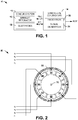
- FIG. 1 illustrates an example of a hemispherical resonator gyroscope (HRG) system 10.
- the HRG 10 can be implemented in any of a variety of applications with which accurate measurement of rotation may be necessary, such as aerospace and nautical navigation.
- the HRG 10 includes a sensing system 12 and a controller 14.
- the sensing system 12 includes an annular resonator 16 that can be arranged as a deformable material having an elastic property and being provided in one of a variety of different forms.
- the annular resonator 16 can be an elastic hemisphere.
- the sensing system 12 also includes a set of electrodes 18 that are arranged internally with respect to the annular resonator 16, such that the annular resonator 16 substantially surrounds the electrodes 18.
- the electrodes 18 are configured to generate electrostatic force in response to forcer signals FRC provided by the controller 14 to provide deformation of the annular resonator 16, such as to provide a periodic motion of the annular resonator 16 in a vibration pattern.
- the vibration pattern can be such that a ratio of the number of electrodes and the number of nodes and antinodes of the vibration pattern is a non-integer number.
- the electrodes 18 can be implemented to provide force-rebalance of the angular displacement of the standing wave on the annular resonator 16 and concurrently provide nulling of the quadrature effects that can degrade or otherwise affect the standing wave.
- the electrodes 18 can include and/or can be implemented as pickoff electrodes that can provide pickoff signals PO corresponding to the motion of the annular resonator 16 to measure the rotation of the sensing system 12 about the sensitive axis.
- the electrodes 18 can include dedicated forcer electrodes and pickoff electrodes, or as a second example, the electrodes 18 could implement dual forcer and pickoff functionality.
- the controller 14 includes a processor 22 and a signal generator 24.
- the signal generator 24 is configured to generate the forcer signals FRC that are provided to the electrodes 18 based on the pickoff signals PO that are provided to the sensing system 12 (e.g., via the signal generator 24) for capacitive measurement of the of the deformation of the annular resonator 16 with respect to the electrodes 18 via the processor 22.
- the forcer signals FRC that are generated by the signal generator 24 can include a number of forcer signals FRC that is a proper subset of the number of electrodes 18.
- the forcer signals FRC can be provided to a first portion of the electrodes 18 to provide the periodic motion of the annular resonator 16 in response to one or more of the pickoff signals PO.
- the pickoff signals PO can be provided to the processor 22 that generates the forcer signals FRC based on a set of distinct equations that are associated with a disparate phase of resultant electrostatic forces provided via the electrodes 18.
- the equations can control the amplitude of the electrostatic force and provide a measure of the rate of angular rotation of the sensing system 12 about the sensitive axis, and also control quadrature effects.
- the controller 14 can provide the measurement of the angular rate of rotation about the input axis as an output signal ROT based on the pickoff signals.
- the HRG 10 can substantially mitigate noise that results from cross-talk between the rate drive and a 1- ⁇ amplitude drive, such as a drive that utilizes sinusoidal forcing signals that vary at the vibration frequency of the resonator, and can substantially mitigate bias instability that results from coupling of the between the 1- ⁇ quadrature drive and the drive.
- FIG. 2 illustrates an example of a sensing system 50.
- the sensing system 50 can correspond to the sensing system 12 in the example of FIG. 1 . Therefore, reference is to be made to the example of FIG. 1 in the following description of the example of FIG. 2 .
- the sensing system 50 includes an annular resonator 52 that substantially surrounds a plurality of electrodes.
- the annular resonator 52 can be configured as an elastic hemispherical shell, but could have other geometric arrangements (e.g., an elastic ring).
- the plurality of electrodes includes a first electrode 54, a second electrode 56, a third electrode 58, a fourth electrode 60, a fifth electrode 62, a sixth electrode 64, a seventh electrode 66, and an eighth electrode 68.
- the electrodes 54, 56, 58, 60, 62, 64, 66, and 68 are arranged in an oppositely-disposed symmetrical annular arrangement about a sensitive axis 70, demonstrated as perpendicular to the plane of the page of FIG. 2 , and thus perpendicular to the axes associated with the vibration pattern, as described in greater detail herein.
- the electrodes 54, 56, 58, 60, 62, 64, 66, and 68 are provided signals ⁇ that can correspond to forcer signals and/or pickoff signals.
- a first signal ⁇ 0 is demonstrated as being provided to the first electrode 54
- a second signal ⁇ 1 is demonstrated as being provided to the second electrode 56
- a third signal ⁇ 3 is demonstrated as being provided to the third electrode 58
- a fourth signal ⁇ 3 is demonstrated as being provided to the fourth electrode 60.
- a fifth signal ⁇ 4 is demonstrated as being provided to the fifth electrode 62
- a sixth signal ⁇ 5 is demonstrated as being provided to the sixth electrode 64
- a seventh signal ⁇ 6 is demonstrated as being provided to the seventh electrode 66
- an eighth signal ⁇ 7 is demonstrated as being provided to the eighth electrode 68. While the example of FIG.
- a signal ⁇ is provided to each of the electrodes 54, 56, 58, 60, 62, 64, 66, and 68
- a proper subset of the signals ⁇ can be provided as forcer voltages ⁇ to a respective proper subset of the electrodes 54, 56, 58, 60, 62, 64, 66, and 68, such as in the example of some of the electrodes 54, 56, 58, 60, 62, 64, 66, and 68 being dedicated to pickoff.
- the electrodes 54, 56, 58, 60, 62, 64, 66, and 68 can provide an electrostatic force that acts upon the annular resonator 52.
- the annular resonator 52 is electrostatically attracted to the electrodes 54, 56, 58, 60, 62, 64, 66, and 68 based on a relative phase of the forcer voltages ⁇ , and thus a relative phase of the electrostatic forces.
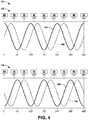
- the state of the annular resonator 52 in response to the application of the forcer voltages ⁇ is demonstrated in the examples of FIGS. 3 and 4 .
- the first state is demonstrated in the example of FIG. 3 at 102 and in the example of FIG. 4 at 152.
- the second state is demonstrated in the example of FIG. 3 at 104 and in the example of FIG. 4 at 154.
- the annular resonator 52 is demonstrated as being extended and contracted along three 120° axes, demonstrated as 106, 108, and 110, and also demonstrates four 90° axes 112, 114, 116, and 118 defined by the electrodes 54, 56, 58, 60, 62, 64, 66, and 68, with the axis 110 being collinear with the axis 112.
- the phase diagram 150 demonstrates a solid-line 156 corresponding to the drive voltage, as applied to the electrodes 54, 56, 58, 60, 62, 64, 66, and 68, and a dotted-line 158 corresponding to the pickoff signal, as detected at the electrodes 54, 56, 58, 60, 62, 64, 66, and 68.
- the first electrode 54 can implement a first anti-node forcer function (e.g., X+) via the signal ⁇ 0
- the second electrode 56 can implement a first in-between pickoff function (e.g., X-/Y+) via the signal ⁇ 1
- the third electrode 58 can implement a second anti-node forcer function (e.g., Y-) via the signal ⁇ 2
- the fourth electrode 60 can implement a second in-between pickoff function (e.g., X+/Y+) via the signal ⁇ 3 .
- the fifth electrode 62 can implement a third anti-node forcer function (e.g., X-) via the signal ⁇ 4
- the sixth electrode 64 can implement a third in-between pickoff function (e.g., X+/Y-) via the signal ⁇ 5
- the seventh electrode 66 can implement a fourth anti-node forcer function (e.g., Y+) via the signal ⁇ 6
- the eighth electrode 68 can implement a fourth in-between pickoff function (e.g., X-/Y-) via the signal ⁇ 7 .
- the first electrode 54 is provided a first forcer voltage ⁇ 0
- the second electrode 56 is provided a second forcer voltage ⁇ 1
- the third electrode 58 is provided a third forcer voltage ⁇ 2
- the fourth electrode 60 is provided a fourth forcer voltage ⁇ 3
- the fifth electrode 62 is provided a fifth forcer voltage ⁇ 4
- the sixth electrode 64 is provided a sixth forcer voltage ⁇ 5
- the seventh electrode 66 is provided a seventh forcer voltage ⁇ 6
- the eighth electrode 68 is provided an eighth forcer voltage ⁇ 7 .
- the second example provides an implementation that provides a 2- ⁇ parametric amplitude drive, DC quadrature control, and a 1- ⁇ rate drive. Therefore, the second example can provide a substantially improved bias instability and noise reduction due to the decoupling of the frequencies of the respective drive signals.
- the first electrode 54 can implement a first parametric drive and DC quadrature function via the signal ⁇ 0
- the second electrode 56 can implement a first in-between pickoff function (e.g., X-/Y+) via the signal ⁇ 1
- the third electrode 58 can implement a parametric drive, rate drive, and DC quadrature function via the signal ⁇ 2
- the fourth electrode 60 can implement a second in-between pickoff function (e.g., X+/Y+) via the signal ⁇ 3 .
- the fifth electrode 62 can implement a second parametric drive and DC quadrature function via the signal ⁇ 4
- the sixth electrode 64 can implement a third in-between pickoff function (e.g., X+/Y-) via the signal ⁇ 5
- the seventh electrode 66 can implement anti-node parametric drive and rate drive function via the signal ⁇ 6
- the eighth electrode 68 can implement a fourth in-between pickoff function (e.g., X-/Y-) via the signal ⁇ 7 .
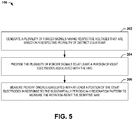
- FIG. 5 a method in accordance with various aspects of the present disclosure will be better appreciated with reference to FIG. 5 . While, for purposes of simplicity of explanation, the method of FIG. 5 is shown and described as executing serially, it is to be understood and appreciated that the present disclosure is not limited by the illustrated order, as some aspects could, in accordance with the present disclosure, occur in different orders and/or concurrently with other aspects from that shown and described herein. Moreover, not all illustrated features may be required to implement a method in accordance with an aspect of the present disclosure.
- FIG. 5 illustrates a method 200 for measuring rotation (e.g., the signal ROT) about a sensitive axis (e.g., the sensitive axis 70) of an HRG (e.g., the HRG 10).
- a plurality of forcer signals e.g., the forcer signals FRC
- respective voltages e.g., the voltages ⁇ 0 , ⁇ 1 , ⁇ 2 , ⁇ 3 , ⁇ 4 , ⁇ 5 , ⁇ 6 , and ⁇ 7
- respective plurality of distinct equations e.g., Equations 1-4 or Equations 5-12.
- the plurality of forcer signals are provided to at least a portion of eight electrodes (e.g., the electrodes 18) associated with the HRG.
- a pickoff e.g., the pickoff signals PO
Landscapes
- Physics & Mathematics (AREA)
- Engineering & Computer Science (AREA)
- General Physics & Mathematics (AREA)
- Radar, Positioning & Navigation (AREA)
- Remote Sensing (AREA)
- Gyroscopes (AREA)
Applications Claiming Priority (1)
| Application Number | Priority Date | Filing Date | Title |
|---|---|---|---|
| US15/296,774 US10584967B2 (en) | 2016-10-18 | 2016-10-18 | Hemispherical resonator gyroscope |
Publications (2)
| Publication Number | Publication Date |
|---|---|
| EP3312558A1 true EP3312558A1 (de) | 2018-04-25 |
| EP3312558B1 EP3312558B1 (de) | 2020-03-18 |
Family
ID=60138265
Family Applications (1)
| Application Number | Title | Priority Date | Filing Date |
|---|---|---|---|
| EP17196984.3A Active EP3312558B1 (de) | 2016-10-18 | 2017-10-18 | Halbkugelförmiges resonatorgyroskop |
Country Status (3)
| Country | Link |
|---|---|
| US (1) | US10584967B2 (de) |
| EP (1) | EP3312558B1 (de) |
| JP (1) | JP6600672B2 (de) |
Families Citing this family (6)
| Publication number | Priority date | Publication date | Assignee | Title |
|---|---|---|---|---|
| GB2568289A (en) * | 2017-11-10 | 2019-05-15 | Atlantic Inertial Systems Ltd | Vibrating structure gyroscopes |
| US11073393B2 (en) * | 2019-01-16 | 2021-07-27 | Northrop Grumman Systems Corporation | Coriolis vibratory gyroscope control system |
| US11073391B2 (en) | 2019-09-26 | 2021-07-27 | Northrop Grumman Systems Corporation | Coriolis vibratory accelerometer system |
| KR102410297B1 (ko) * | 2020-09-16 | 2022-06-16 | 주식회사 한화 | 진동형 자이로스코프의 공진기 전극 구조체 |
| CN112595303B (zh) * | 2020-12-10 | 2022-09-23 | 华中光电技术研究所(中国船舶重工集团公司第七一七研究所) | 一种hrg全角模式下参数计算方法 |
| CN117490729B (zh) * | 2024-01-03 | 2024-03-19 | 四川图林科技有限责任公司 | 一种半球谐振陀螺仪的正交漂移误差检测方法 |
Citations (2)
| Publication number | Priority date | Publication date | Assignee | Title |
|---|---|---|---|---|
| US7874209B2 (en) * | 2008-01-08 | 2011-01-25 | Northrop Grumman Guidance And Electronics Company, Inc. | Capacitive bulk acoustic wave disk gyroscopes with self-calibration |
| EP3056859A1 (de) * | 2015-02-10 | 2016-08-17 | Northrop Grumman Systems Corporation | Vorspannungs- und massstabfehlerabschwächung in einem coriolis-vibrationskreiselsystem |
Family Cites Families (10)
| Publication number | Priority date | Publication date | Assignee | Title |
|---|---|---|---|---|
| WO2004085963A1 (en) * | 2003-03-28 | 2004-10-07 | Bae Systems Plc | A rate sensing device |
| US7318347B2 (en) * | 2005-05-09 | 2008-01-15 | Northrop Grumman Corporation | Hemispherical resonator gyro control |
| US7281426B1 (en) | 2006-06-15 | 2007-10-16 | Innalabs Technologies, Inc. | Stemless hemispherical resonator gyroscope |
| FR2920224B1 (fr) | 2007-08-23 | 2009-10-02 | Sagem Defense Securite | Procede de determination d'une vitesse de rotation d'un capteur vibrant axisymetrique, et dispositif inertiel mettant en oeuvre le procede |
| FR2925669B1 (fr) | 2007-12-21 | 2010-01-15 | Sagem Defense Securite | Mesure par systeme gyroscopique |
| US8205495B2 (en) | 2008-06-10 | 2012-06-26 | The Boeing Company | Systematic disc resonator gyroscope tuning |
| US7912664B2 (en) | 2008-09-11 | 2011-03-22 | Northrop Grumman Guidance And Electronics Company, Inc. | Self calibrating gyroscope system |
| US8567247B2 (en) | 2009-10-12 | 2013-10-29 | The Regents Of The University Of California | Three-dimensional wafer-scale batch-micromachined sensor and method of fabrication for the same |
| US8763441B2 (en) | 2011-11-22 | 2014-07-01 | Georgia Tech Research Corporation | Method and apparatus for self-calibration of gyroscopes |
| EP4056949A3 (de) | 2016-09-09 | 2022-12-21 | NextNav, LLC | Systeme und verfahren zur kalibrierung von instabilen sensoren |
-
2016
- 2016-10-18 US US15/296,774 patent/US10584967B2/en active Active
-
2017
- 2017-10-18 JP JP2017201755A patent/JP6600672B2/ja active Active
- 2017-10-18 EP EP17196984.3A patent/EP3312558B1/de active Active
Patent Citations (2)
| Publication number | Priority date | Publication date | Assignee | Title |
|---|---|---|---|---|
| US7874209B2 (en) * | 2008-01-08 | 2011-01-25 | Northrop Grumman Guidance And Electronics Company, Inc. | Capacitive bulk acoustic wave disk gyroscopes with self-calibration |
| EP3056859A1 (de) * | 2015-02-10 | 2016-08-17 | Northrop Grumman Systems Corporation | Vorspannungs- und massstabfehlerabschwächung in einem coriolis-vibrationskreiselsystem |
Non-Patent Citations (1)
| Title |
|---|
| ZOTOV SERGEI A ET AL: "Utilization of mechanical quadrature in silicon MEMS vibratory gyroscope to increase and expand the long term in-run bias stability", 2014 INTERNATIONAL SYMPOSIUM ON INERTIAL SENSORS AND SYSTEMS (ISISS), IEEE, 25 February 2014 (2014-02-25), pages 1 - 4, XP032583939, DOI: 10.1109/ISISS.2014.6782536 * |
Also Published As
| Publication number | Publication date |
|---|---|
| JP2018091831A (ja) | 2018-06-14 |
| US20180231383A1 (en) | 2018-08-16 |
| EP3312558B1 (de) | 2020-03-18 |
| JP6600672B2 (ja) | 2019-10-30 |
| US10584967B2 (en) | 2020-03-10 |
Similar Documents
| Publication | Publication Date | Title |
|---|---|---|
| EP3312558B1 (de) | Halbkugelförmiges resonatorgyroskop | |
| US10436588B2 (en) | Vibrating-mass gyroscope systems and method | |
| US7874209B2 (en) | Capacitive bulk acoustic wave disk gyroscopes with self-calibration | |
| US11015934B2 (en) | Vibrating-mass gyroscope systems and method | |
| KR101178692B1 (ko) | 코리올리 자이로스코프 | |
| US7765869B2 (en) | Combined accelerometer and gyroscope system | |
| EP2696169B1 (de) | Coriolis-vibrationskreisel mit kraftausgleich | |
| US10809061B2 (en) | Vibratory gyroscope including a plurality of inertial bodies | |
| US11390517B2 (en) | Systems and methods for bias suppression in a non-degenerate MEMS sensor | |
| Peng et al. | An automatically mode-matched MEMS gyroscope based on phase characteristics | |
| EP3330665B1 (de) | Resonatorkreisel mit dualem vibrationsmuster | |
| EP3495772B1 (de) | Schwingungsmassen-gyroskopsystem | |
| Maslov et al. | Methods to eliminate nonlinearity of electrostatic control sensors of the wave solid-state gyroscope | |
| EP2775258B1 (de) | Mikroelektromechanischer Kreisel | |
| Chikovani et al. | Errors compensation of ring-type MEMS gyroscopes operating in differential mode,[in:] | |
| US11788840B2 (en) | Vibrating-mass sensor system | |
| Gallacher et al. | The application of parametric excitation in MEMS gyroscopes |
Legal Events
| Date | Code | Title | Description |
|---|---|---|---|
| PUAI | Public reference made under article 153(3) epc to a published international application that has entered the european phase |
Free format text: ORIGINAL CODE: 0009012 |
|
| STAA | Information on the status of an ep patent application or granted ep patent |
Free format text: STATUS: THE APPLICATION HAS BEEN PUBLISHED |
|
| AK | Designated contracting states |
Kind code of ref document: A1 Designated state(s): AL AT BE BG CH CY CZ DE DK EE ES FI FR GB GR HR HU IE IS IT LI LT LU LV MC MK MT NL NO PL PT RO RS SE SI SK SM TR |
|
| AX | Request for extension of the european patent |
Extension state: BA ME |
|
| RIN1 | Information on inventor provided before grant (corrected) |
Inventor name: LYNCH, DAVID D. Inventor name: TRUSOV, ALEXANDER Inventor name: ROZELLE, DAVID M. |
|
| STAA | Information on the status of an ep patent application or granted ep patent |
Free format text: STATUS: REQUEST FOR EXAMINATION WAS MADE |
|
| 17P | Request for examination filed |
Effective date: 20180618 |
|
| RBV | Designated contracting states (corrected) |
Designated state(s): AL AT BE BG CH CY CZ DE DK EE ES FI FR GB GR HR HU IE IS IT LI LT LU LV MC MK MT NL NO PL PT RO RS SE SI SK SM TR |
|
| GRAP | Despatch of communication of intention to grant a patent |
Free format text: ORIGINAL CODE: EPIDOSNIGR1 |
|
| STAA | Information on the status of an ep patent application or granted ep patent |
Free format text: STATUS: GRANT OF PATENT IS INTENDED |
|
| INTG | Intention to grant announced |
Effective date: 20191025 |
|
| GRAS | Grant fee paid |
Free format text: ORIGINAL CODE: EPIDOSNIGR3 |
|
| GRAA | (expected) grant |
Free format text: ORIGINAL CODE: 0009210 |
|
| STAA | Information on the status of an ep patent application or granted ep patent |
Free format text: STATUS: THE PATENT HAS BEEN GRANTED |
|
| AK | Designated contracting states |
Kind code of ref document: B1 Designated state(s): AL AT BE BG CH CY CZ DE DK EE ES FI FR GB GR HR HU IE IS IT LI LT LU LV MC MK MT NL NO PL PT RO RS SE SI SK SM TR |
|
| REG | Reference to a national code |
Ref country code: GB Ref legal event code: FG4D |
|
| REG | Reference to a national code |
Ref country code: DE Ref legal event code: R096 Ref document number: 602017013185 Country of ref document: DE |
|
| REG | Reference to a national code |
Ref country code: AT Ref legal event code: REF Ref document number: 1246403 Country of ref document: AT Kind code of ref document: T Effective date: 20200415 Ref country code: IE Ref legal event code: FG4D |
|
| REG | Reference to a national code |
Ref country code: DE Ref legal event code: R082 Ref document number: 602017013185 Country of ref document: DE Representative=s name: FARAGO PATENTANWALTS- UND RECHTSANWALTSGESELLS, DE |
|
| PG25 | Lapsed in a contracting state [announced via postgrant information from national office to epo] |
Ref country code: RS Free format text: LAPSE BECAUSE OF FAILURE TO SUBMIT A TRANSLATION OF THE DESCRIPTION OR TO PAY THE FEE WITHIN THE PRESCRIBED TIME-LIMIT Effective date: 20200318 Ref country code: NO Free format text: LAPSE BECAUSE OF FAILURE TO SUBMIT A TRANSLATION OF THE DESCRIPTION OR TO PAY THE FEE WITHIN THE PRESCRIBED TIME-LIMIT Effective date: 20200618 Ref country code: FI Free format text: LAPSE BECAUSE OF FAILURE TO SUBMIT A TRANSLATION OF THE DESCRIPTION OR TO PAY THE FEE WITHIN THE PRESCRIBED TIME-LIMIT Effective date: 20200318 |
|
| REG | Reference to a national code |
Ref country code: NL Ref legal event code: MP Effective date: 20200318 |
|
| PG25 | Lapsed in a contracting state [announced via postgrant information from national office to epo] |
Ref country code: HR Free format text: LAPSE BECAUSE OF FAILURE TO SUBMIT A TRANSLATION OF THE DESCRIPTION OR TO PAY THE FEE WITHIN THE PRESCRIBED TIME-LIMIT Effective date: 20200318 Ref country code: SE Free format text: LAPSE BECAUSE OF FAILURE TO SUBMIT A TRANSLATION OF THE DESCRIPTION OR TO PAY THE FEE WITHIN THE PRESCRIBED TIME-LIMIT Effective date: 20200318 Ref country code: LV Free format text: LAPSE BECAUSE OF FAILURE TO SUBMIT A TRANSLATION OF THE DESCRIPTION OR TO PAY THE FEE WITHIN THE PRESCRIBED TIME-LIMIT Effective date: 20200318 Ref country code: GR Free format text: LAPSE BECAUSE OF FAILURE TO SUBMIT A TRANSLATION OF THE DESCRIPTION OR TO PAY THE FEE WITHIN THE PRESCRIBED TIME-LIMIT Effective date: 20200619 Ref country code: BG Free format text: LAPSE BECAUSE OF FAILURE TO SUBMIT A TRANSLATION OF THE DESCRIPTION OR TO PAY THE FEE WITHIN THE PRESCRIBED TIME-LIMIT Effective date: 20200618 |
|
| REG | Reference to a national code |
Ref country code: LT Ref legal event code: MG4D |
|
| PG25 | Lapsed in a contracting state [announced via postgrant information from national office to epo] |
Ref country code: NL Free format text: LAPSE BECAUSE OF FAILURE TO SUBMIT A TRANSLATION OF THE DESCRIPTION OR TO PAY THE FEE WITHIN THE PRESCRIBED TIME-LIMIT Effective date: 20200318 |
|
| PG25 | Lapsed in a contracting state [announced via postgrant information from national office to epo] |
Ref country code: EE Free format text: LAPSE BECAUSE OF FAILURE TO SUBMIT A TRANSLATION OF THE DESCRIPTION OR TO PAY THE FEE WITHIN THE PRESCRIBED TIME-LIMIT Effective date: 20200318 Ref country code: SM Free format text: LAPSE BECAUSE OF FAILURE TO SUBMIT A TRANSLATION OF THE DESCRIPTION OR TO PAY THE FEE WITHIN THE PRESCRIBED TIME-LIMIT Effective date: 20200318 Ref country code: LT Free format text: LAPSE BECAUSE OF FAILURE TO SUBMIT A TRANSLATION OF THE DESCRIPTION OR TO PAY THE FEE WITHIN THE PRESCRIBED TIME-LIMIT Effective date: 20200318 Ref country code: PT Free format text: LAPSE BECAUSE OF FAILURE TO SUBMIT A TRANSLATION OF THE DESCRIPTION OR TO PAY THE FEE WITHIN THE PRESCRIBED TIME-LIMIT Effective date: 20200812 Ref country code: SK Free format text: LAPSE BECAUSE OF FAILURE TO SUBMIT A TRANSLATION OF THE DESCRIPTION OR TO PAY THE FEE WITHIN THE PRESCRIBED TIME-LIMIT Effective date: 20200318 Ref country code: CZ Free format text: LAPSE BECAUSE OF FAILURE TO SUBMIT A TRANSLATION OF THE DESCRIPTION OR TO PAY THE FEE WITHIN THE PRESCRIBED TIME-LIMIT Effective date: 20200318 Ref country code: IS Free format text: LAPSE BECAUSE OF FAILURE TO SUBMIT A TRANSLATION OF THE DESCRIPTION OR TO PAY THE FEE WITHIN THE PRESCRIBED TIME-LIMIT Effective date: 20200718 Ref country code: RO Free format text: LAPSE BECAUSE OF FAILURE TO SUBMIT A TRANSLATION OF THE DESCRIPTION OR TO PAY THE FEE WITHIN THE PRESCRIBED TIME-LIMIT Effective date: 20200318 |
|
| REG | Reference to a national code |
Ref country code: AT Ref legal event code: MK05 Ref document number: 1246403 Country of ref document: AT Kind code of ref document: T Effective date: 20200318 |
|
| REG | Reference to a national code |
Ref country code: DE Ref legal event code: R097 Ref document number: 602017013185 Country of ref document: DE |
|
| PLBE | No opposition filed within time limit |
Free format text: ORIGINAL CODE: 0009261 |
|
| STAA | Information on the status of an ep patent application or granted ep patent |
Free format text: STATUS: NO OPPOSITION FILED WITHIN TIME LIMIT |
|
| PG25 | Lapsed in a contracting state [announced via postgrant information from national office to epo] |
Ref country code: ES Free format text: LAPSE BECAUSE OF FAILURE TO SUBMIT A TRANSLATION OF THE DESCRIPTION OR TO PAY THE FEE WITHIN THE PRESCRIBED TIME-LIMIT Effective date: 20200318 Ref country code: DK Free format text: LAPSE BECAUSE OF FAILURE TO SUBMIT A TRANSLATION OF THE DESCRIPTION OR TO PAY THE FEE WITHIN THE PRESCRIBED TIME-LIMIT Effective date: 20200318 Ref country code: AT Free format text: LAPSE BECAUSE OF FAILURE TO SUBMIT A TRANSLATION OF THE DESCRIPTION OR TO PAY THE FEE WITHIN THE PRESCRIBED TIME-LIMIT Effective date: 20200318 |
|
| 26N | No opposition filed |
Effective date: 20201221 |
|
| PG25 | Lapsed in a contracting state [announced via postgrant information from national office to epo] |
Ref country code: PL Free format text: LAPSE BECAUSE OF FAILURE TO SUBMIT A TRANSLATION OF THE DESCRIPTION OR TO PAY THE FEE WITHIN THE PRESCRIBED TIME-LIMIT Effective date: 20200318 |
|
| PG25 | Lapsed in a contracting state [announced via postgrant information from national office to epo] |
Ref country code: SI Free format text: LAPSE BECAUSE OF FAILURE TO SUBMIT A TRANSLATION OF THE DESCRIPTION OR TO PAY THE FEE WITHIN THE PRESCRIBED TIME-LIMIT Effective date: 20200318 |
|
| REG | Reference to a national code |
Ref country code: CH Ref legal event code: PL |
|
| PG25 | Lapsed in a contracting state [announced via postgrant information from national office to epo] |
Ref country code: LU Free format text: LAPSE BECAUSE OF NON-PAYMENT OF DUE FEES Effective date: 20201018 Ref country code: MC Free format text: LAPSE BECAUSE OF FAILURE TO SUBMIT A TRANSLATION OF THE DESCRIPTION OR TO PAY THE FEE WITHIN THE PRESCRIBED TIME-LIMIT Effective date: 20200318 |
|
| REG | Reference to a national code |
Ref country code: BE Ref legal event code: MM Effective date: 20201031 |
|
| PG25 | Lapsed in a contracting state [announced via postgrant information from national office to epo] |
Ref country code: LI Free format text: LAPSE BECAUSE OF NON-PAYMENT OF DUE FEES Effective date: 20201031 Ref country code: BE Free format text: LAPSE BECAUSE OF NON-PAYMENT OF DUE FEES Effective date: 20201031 Ref country code: CH Free format text: LAPSE BECAUSE OF NON-PAYMENT OF DUE FEES Effective date: 20201031 |
|
| PG25 | Lapsed in a contracting state [announced via postgrant information from national office to epo] |
Ref country code: IE Free format text: LAPSE BECAUSE OF NON-PAYMENT OF DUE FEES Effective date: 20201018 |
|
| PG25 | Lapsed in a contracting state [announced via postgrant information from national office to epo] |
Ref country code: TR Free format text: LAPSE BECAUSE OF FAILURE TO SUBMIT A TRANSLATION OF THE DESCRIPTION OR TO PAY THE FEE WITHIN THE PRESCRIBED TIME-LIMIT Effective date: 20200318 Ref country code: MT Free format text: LAPSE BECAUSE OF FAILURE TO SUBMIT A TRANSLATION OF THE DESCRIPTION OR TO PAY THE FEE WITHIN THE PRESCRIBED TIME-LIMIT Effective date: 20200318 Ref country code: CY Free format text: LAPSE BECAUSE OF FAILURE TO SUBMIT A TRANSLATION OF THE DESCRIPTION OR TO PAY THE FEE WITHIN THE PRESCRIBED TIME-LIMIT Effective date: 20200318 |
|
| PG25 | Lapsed in a contracting state [announced via postgrant information from national office to epo] |
Ref country code: MK Free format text: LAPSE BECAUSE OF FAILURE TO SUBMIT A TRANSLATION OF THE DESCRIPTION OR TO PAY THE FEE WITHIN THE PRESCRIBED TIME-LIMIT Effective date: 20200318 Ref country code: AL Free format text: LAPSE BECAUSE OF FAILURE TO SUBMIT A TRANSLATION OF THE DESCRIPTION OR TO PAY THE FEE WITHIN THE PRESCRIBED TIME-LIMIT Effective date: 20200318 |
|
| REG | Reference to a national code |
Ref country code: DE Ref legal event code: R082 Ref document number: 602017013185 Country of ref document: DE Representative=s name: FARAGO PATENTANWAELTE GMBH, DE Ref country code: DE Ref legal event code: R082 Ref document number: 602017013185 Country of ref document: DE Representative=s name: FARAGO PATENTANWALTSGESELLSCHAFT MBH, DE |
|
| P01 | Opt-out of the competence of the unified patent court (upc) registered |
Effective date: 20230607 |
|
| PGFP | Annual fee paid to national office [announced via postgrant information from national office to epo] |
Ref country code: DE Payment date: 20251021 Year of fee payment: 9 |
|
| PGFP | Annual fee paid to national office [announced via postgrant information from national office to epo] |
Ref country code: GB Payment date: 20251022 Year of fee payment: 9 |
|
| PGFP | Annual fee paid to national office [announced via postgrant information from national office to epo] |
Ref country code: IT Payment date: 20251024 Year of fee payment: 9 |
|
| PGFP | Annual fee paid to national office [announced via postgrant information from national office to epo] |
Ref country code: FR Payment date: 20251030 Year of fee payment: 9 |