EP3312592B1 - Dispositif et procédé de détection de bulles d'air dans un récipient rempli de liquide - Google Patents
Dispositif et procédé de détection de bulles d'air dans un récipient rempli de liquide Download PDFInfo
- Publication number
- EP3312592B1 EP3312592B1 EP17184327.9A EP17184327A EP3312592B1 EP 3312592 B1 EP3312592 B1 EP 3312592B1 EP 17184327 A EP17184327 A EP 17184327A EP 3312592 B1 EP3312592 B1 EP 3312592B1
- Authority
- EP
- European Patent Office
- Prior art keywords
- container
- light sources
- light
- recording unit
- unit
- Prior art date
- Legal status (The legal status is an assumption and is not a legal conclusion. Google has not performed a legal analysis and makes no representation as to the accuracy of the status listed.)
- Active
Links
Images





Classifications
-
- G—PHYSICS
- G01—MEASURING; TESTING
- G01N—INVESTIGATING OR ANALYSING MATERIALS BY DETERMINING THEIR CHEMICAL OR PHYSICAL PROPERTIES
- G01N21/00—Investigating or analysing materials by the use of optical means, i.e. using sub-millimetre waves, infrared, visible or ultraviolet light
- G01N21/84—Systems specially adapted for particular applications
- G01N21/88—Investigating the presence of flaws or contamination
- G01N21/90—Investigating the presence of flaws or contamination in a container or its contents
- G01N21/9018—Dirt detection in containers
- G01N21/9027—Dirt detection in containers in containers after filling
-
- G—PHYSICS
- G01—MEASURING; TESTING
- G01N—INVESTIGATING OR ANALYSING MATERIALS BY DETERMINING THEIR CHEMICAL OR PHYSICAL PROPERTIES
- G01N15/00—Investigating characteristics of particles; Investigating permeability, pore-volume or surface-area of porous materials
- G01N15/10—Investigating individual particles
- G01N15/14—Optical investigation techniques, e.g. flow cytometry
- G01N15/1429—Signal processing
- G01N15/1433—Signal processing using image recognition
-
- G—PHYSICS
- G01—MEASURING; TESTING
- G01N—INVESTIGATING OR ANALYSING MATERIALS BY DETERMINING THEIR CHEMICAL OR PHYSICAL PROPERTIES
- G01N15/00—Investigating characteristics of particles; Investigating permeability, pore-volume or surface-area of porous materials
- G01N15/10—Investigating individual particles
- G01N15/14—Optical investigation techniques, e.g. flow cytometry
- G01N15/1434—Optical arrangements
-
- G—PHYSICS
- G01—MEASURING; TESTING
- G01N—INVESTIGATING OR ANALYSING MATERIALS BY DETERMINING THEIR CHEMICAL OR PHYSICAL PROPERTIES
- G01N21/00—Investigating or analysing materials by the use of optical means, i.e. using sub-millimetre waves, infrared, visible or ultraviolet light
- G01N21/17—Systems in which incident light is modified in accordance with the properties of the material investigated
- G01N21/21—Polarisation-affecting properties
- G01N21/211—Ellipsometry
-
- G—PHYSICS
- G01—MEASURING; TESTING
- G01N—INVESTIGATING OR ANALYSING MATERIALS BY DETERMINING THEIR CHEMICAL OR PHYSICAL PROPERTIES
- G01N21/00—Investigating or analysing materials by the use of optical means, i.e. using sub-millimetre waves, infrared, visible or ultraviolet light
- G01N21/17—Systems in which incident light is modified in accordance with the properties of the material investigated
- G01N21/47—Scattering, i.e. diffuse reflection
- G01N21/49—Scattering, i.e. diffuse reflection within a body or fluid
- G01N21/51—Scattering, i.e. diffuse reflection within a body or fluid inside a container, e.g. in an ampoule
-
- G—PHYSICS
- G01—MEASURING; TESTING
- G01N—INVESTIGATING OR ANALYSING MATERIALS BY DETERMINING THEIR CHEMICAL OR PHYSICAL PROPERTIES
- G01N21/00—Investigating or analysing materials by the use of optical means, i.e. using sub-millimetre waves, infrared, visible or ultraviolet light
- G01N21/84—Systems specially adapted for particular applications
- G01N21/88—Investigating the presence of flaws or contamination
- G01N21/8806—Specially adapted optical and illumination features
-
- G—PHYSICS
- G01—MEASURING; TESTING
- G01N—INVESTIGATING OR ANALYSING MATERIALS BY DETERMINING THEIR CHEMICAL OR PHYSICAL PROPERTIES
- G01N21/00—Investigating or analysing materials by the use of optical means, i.e. using sub-millimetre waves, infrared, visible or ultraviolet light
- G01N21/84—Systems specially adapted for particular applications
- G01N21/88—Investigating the presence of flaws or contamination
- G01N21/90—Investigating the presence of flaws or contamination in a container or its contents
- G01N21/9036—Investigating the presence of flaws or contamination in a container or its contents using arrays of emitters or receivers
-
- G—PHYSICS
- G01—MEASURING; TESTING
- G01N—INVESTIGATING OR ANALYSING MATERIALS BY DETERMINING THEIR CHEMICAL OR PHYSICAL PROPERTIES
- G01N15/00—Investigating characteristics of particles; Investigating permeability, pore-volume or surface-area of porous materials
- G01N2015/0007—Investigating dispersion of gas
- G01N2015/0011—Investigating dispersion of gas in liquids, e.g. bubbles
-
- G—PHYSICS
- G01—MEASURING; TESTING
- G01N—INVESTIGATING OR ANALYSING MATERIALS BY DETERMINING THEIR CHEMICAL OR PHYSICAL PROPERTIES
- G01N15/00—Investigating characteristics of particles; Investigating permeability, pore-volume or surface-area of porous materials
- G01N15/10—Investigating individual particles
- G01N15/14—Optical investigation techniques, e.g. flow cytometry
- G01N15/1434—Optical arrangements
- G01N2015/144—Imaging characterised by its optical setup
-
- G—PHYSICS
- G01—MEASURING; TESTING
- G01N—INVESTIGATING OR ANALYSING MATERIALS BY DETERMINING THEIR CHEMICAL OR PHYSICAL PROPERTIES
- G01N15/00—Investigating characteristics of particles; Investigating permeability, pore-volume or surface-area of porous materials
- G01N15/10—Investigating individual particles
- G01N15/14—Optical investigation techniques, e.g. flow cytometry
- G01N2015/1493—Particle size
-
- G—PHYSICS
- G01—MEASURING; TESTING
- G01N—INVESTIGATING OR ANALYSING MATERIALS BY DETERMINING THEIR CHEMICAL OR PHYSICAL PROPERTIES
- G01N21/00—Investigating or analysing materials by the use of optical means, i.e. using sub-millimetre waves, infrared, visible or ultraviolet light
- G01N21/84—Systems specially adapted for particular applications
- G01N21/88—Investigating the presence of flaws or contamination
- G01N21/8806—Specially adapted optical and illumination features
- G01N2021/8822—Dark field detection
-
- G—PHYSICS
- G01—MEASURING; TESTING
- G01N—INVESTIGATING OR ANALYSING MATERIALS BY DETERMINING THEIR CHEMICAL OR PHYSICAL PROPERTIES
- G01N21/00—Investigating or analysing materials by the use of optical means, i.e. using sub-millimetre waves, infrared, visible or ultraviolet light
- G01N21/84—Systems specially adapted for particular applications
- G01N21/88—Investigating the presence of flaws or contamination
- G01N21/8806—Specially adapted optical and illumination features
- G01N2021/8845—Multiple wavelengths of illumination or detection
-
- G—PHYSICS
- G01—MEASURING; TESTING
- G01N—INVESTIGATING OR ANALYSING MATERIALS BY DETERMINING THEIR CHEMICAL OR PHYSICAL PROPERTIES
- G01N21/00—Investigating or analysing materials by the use of optical means, i.e. using sub-millimetre waves, infrared, visible or ultraviolet light
- G01N21/84—Systems specially adapted for particular applications
- G01N21/88—Investigating the presence of flaws or contamination
- G01N21/8806—Specially adapted optical and illumination features
- G01N2021/8848—Polarisation of light
Definitions
- the present invention relates to a device for detecting air bubbles in a container filled with liquid and to a method directed thereto.
- Fully automatic inspection systems based on image processing are used in a variety of technical areas, such as the pharmaceutical industry, the beverage industry or the semiconductor industry, in order to detect faulty products and to remove them from the further production process, such as packaging, filling or delivery.
- the image processing system mentioned usually comprises one or more optical sensors (e.g. CCD/CMOS cameras) and is equipped with other optical components (e.g. lenses), signal lines, and a computer-aided evaluation unit for the analog or digital signals recorded by the sensor.
- optical sensors e.g. CCD/CMOS cameras
- other optical components e.g. lenses
- signal lines e.g. signals
- computer-aided evaluation unit for the analog or digital signals recorded by the sensor.
- Air bubbles are usually the main cause of false rejection (FR). False rejection is the mistaken classification of an otherwise correct product as faulty, which leads to removal from the manufacturing process. This can be rising/moving air bubbles in the liquid volume or air bubbles adhering to the inner wall of the container. The air bubbles can be incorrectly interpreted as particles, contamination, inclusions, scratches or cracks (etc.). Air bubbles can arise during filling due to mechanical handling or internal (chemical-physical) processes. The amount of air bubbles and their residence time can vary greatly, depending on the properties of the product.
- Optical devices are known by means of which liquids in containers can be optically inspected and inhomogeneities such as air bubbles can be detected.
- the containers are illuminated by several light sources of different wavelengths and images of the liquids are recorded and analyzed, with the light rays of the various light sources running parallel to each other.
- the EP 0 429 086 A1 discloses an inspection device with dark field illumination, which can comprise one or more light sources.
- the possibility can be provided of using an area of the illumination unit not used for dark field illumination as an additional light source for bright field illumination, which differs in its properties from dark field illumination in terms of color or polarization.
- DE 10 2010 012570 A1 discloses a device for inspecting filled containers with a first radiation device which directs radiation at the liquid to be examined in the container, with an image recording device which records at least part of the radiation directed at the liquid by the first radiation device and reflected or scattered by the container, wherein the image recording device is designed to record a spatially resolved image, wherein the device has at least one further radiation device or a further image recording device, wherein the radiation devices and the image recording device are arranged such that the liquid is observed using at least two mutually different image recording paths.
- the aim of the present invention is to provide a device or a method that overcomes the aforementioned disadvantages of the prior art. This is achieved with a device that has all the features of claim 1 or with a method according to claim 12.
- the device according to the invention for detecting air bubbles in a container filled with liquid comprises an illumination unit for irradiating the container with light, and a recording unit for recording an image of the container irradiated by the illumination unit, wherein the illumination unit comprises at least two light sources which differ from one another in their spectral light color and/or their polarization and/or another optical property.
- the device further comprises an evaluation unit which is designed to conclude the presence of an air bubble when evaluating the image of the recording unit on the basis of a specific arrangement of the mutually distinguishable light beams emitted by the light sources.
- the invention provides that the light rays of the at least two
- Light sources in an inspection area for a container do not run parallel to each other. Rather, the beams belonging to a respective light source are at an angle to each of the other beams of the other light sources. Preferably, this angular offset of the
- Beams of at least two light sources only present in a common plane.
- This effect can be exploited to assess whether an air bubble or a foreign particle such as a vitreous body is contained in the liquid by using at least two light sources that differ from each other in their spectral light color and/or their polarization.
- the recording unit is positioned such that the light beams emanating from the at least two light sources do not penetrate into the recording area of the recording unit or have a continuous or uniform intensity in the recording area when passing through the container, which is free of air bubbles or other foreign particles.
- the light beams emitted by the two light sources miss the recording unit, for example, if they are not deflected by foreign particles in the liquid of the container. Exceptions to this are the edge areas of the container, since the bottom surface of a container or the closure can lead to a deflection of the light rays of the at least two light sources into the recording unit.
- an air bubble will inevitably deflect the light in the direction of the recording unit, making it possible to detect the presence of an air bubble or a glass particle.
- the property of an air bubble in a liquid is used to do this, whereby it acts like a concave lens.
- the beam paths of the at least two light sources miss the recording field of the recording unit when inspecting a container that is free of air bubbles or foreign particles, since any deflection of the light beams caused by air bubbles or other particles (e.g. glass particles) is reflected in a detectable increase in the intensity of light beams from the at least two light sources.
- an air bubble in liquid acts like a concave lens and thus leads to a specific deflection of the light rays of the at least two
- the lighting unit comprises three light sources which differ from one another in their spectral light colour and/or their polarisation.
- the recording unit is a color camera and/or a camera with one or more polarization filters. It is possible to record the light rays from several light sources simultaneously or sequentially and to send this information to an evaluation unit. Even images taken in quick succession, for example through different polarizing filters, can be used for evaluation.
- the container can be arranged between the lighting unit and the recording unit and the lighting unit and the recording unit face each other, preferably in order to provide transmitted light illumination of the container.
- transmitted light illumination it is typical that part of the light emitted by the illumination unit passes through the container and only then reaches the recording unit.
- the device comprises a lens which is arranged in the beam path from the lighting unit to the recording unit and is designed to direct the light beams of the at least two light sources of the lighting unit more or less parallel to an inspection area of a container.
- the lens is a cylindrical lens, a Fresnel lens and/or a Fresnel cylindrical lens.
- the lens By providing a lens, it is possible to provide several light sources that are spatially spaced apart from one another, the light rays of which are directed by means of the lens onto a common inspection area in which all light rays from the various light sources are present in accordance with the modifications described above. It is therefore possible that the light rays from the respective light sources in the inspection area do not run parallel to one another but together enclose an angle.
- exactly one of the at least two light sources is arranged at the focal point of the lens, with the remaining light sources of the lighting unit being spaced therefrom on the same side of the lens as the light source arranged at the focal point.
- the other light sources are spaced from the one arranged at the focal point.
- each of the plurality of light sources of the lighting unit is a line light, wherein when the line lights are aligned with each other, their longitudinal directions can be parallel but not identical to each other.
- a line light is characterized by its linear shape and the resulting emission of light, in which a light is emitted along a longitudinal direction of the line light.
- the line light of a respective light source is arranged parallel to a cylinder axis of a cylindrical lens arranged in the beam path from the lighting unit to the recording unit.
- the plurality of line lights can be arranged offset in a direction perpendicular to the cylinder axis of the cylindrical lens.
- a first of the light sources has the color red
- a second of the light sources has the color green
- a third of the light sources has the color blue.
- the recording unit prefferably be an RGB color camera, which, for example, has a Bayer pattern in RGB.
- the container to be tested is completely or partially transparent and can be, for example, a syringe, a vial or an ampoule.
- the liquid present in the container to be tested is a transparent liquid.
- the invention further relates to a method for detecting air bubbles in a container filled with liquid, which is carried out using a device according to one of the preceding variations.
- the container is irradiated with a lighting unit, an image of the container irradiated by the lighting unit is recorded by a recording unit and the image is evaluated by an evaluation unit.
- the container is irradiated by at least two light sources of the lighting unit, which differ from one another in their spectral light color and/or their polarization.
- the light beams emanating from the at least two light sources do not run parallel to one another in an inspection area for the container and, when passing through the container, which is free of air bubbles or other foreign particles, do not penetrate into the recording area of the recording unit or have a continuous or uniform intensity in the recording area of the recording unit.
- the presence of an air bubble is determined when the image is evaluated on the basis of a specific arrangement of the distinguishable light rays emitted by the light sources.
- the presence of an air bubble is inferred when the image shows a specific arrangement of the distinguishable light beams emitted by the light sources, which corresponds to the actual arrangement positioning of a subgroup of the light sources or of all the light sources in the lighting unit.
- Fig. 1 shows three example images of containers 3 in whose liquid an air bubble 1 is present.
- the air bubble 1 is arranged in a circle added to the drawing. Although the air bubbles 1 appear essentially circular, this feature alone is not sufficient to distinguish them from other defects. If one were to rely only on this feature, the presence of circular glass particles 81, for example, would not be detectable.
- Fig. 2 shows the basic structure of an embodiment of a device according to the invention. One can see the
- Lighting unit 4 which comprises several light sources 41, 42, 43.
- the light source 41 is a light with the spectral color red
- the light source 42 is a light with the spectral color green
- the light source 43 is a light with the spectral color blue (the different colors are shown in the Figs. 2 - 4 represented by different dashes).
- Light rays emanating from the individual light sources 41, 42, 43 are directed by a Fresnel cylinder lens 7 onto an inspection area of a container 3.
- the container 3 is filled with a liquid 2 in which an air bubble 1 and a glass particle 81 are present.
- the beam path of the individual light rays of the several light sources 41, 42, 43 changes depending on whether the rays hit the air bubble 1 present in the water or the glass particle 81.
- the deflection of the light rays is recorded by a recording unit 5, here a camera.
- the lighting should be optimized for the detection of air bubbles 1 in order to provide the software with additional options.
- the inspection for defects 8 (cracks 82 in the side wall, particles 81) must not be impaired. Inspection and differentiation should take place simultaneously; a statement about whether air bubbles 1 are present alone is insufficient. Instead, all air bubbles 1 present should be ignored and defects 8 between them should be recognized as such.
- Three line lights 41, 42, 43 in different colors are positioned behind a (Fresnel) lens 7 in such a way that three more or less parallel beams are produced.
- the middle beam should be well parallelized, i.e. the line light 42 should be positioned quite precisely at the focal point of the lens 7.
- the (green) background appears relatively homogeneous, and the parallelism also leads to a very good contrast, both for defects 8 and for air bubbles 1 and also for other irregularities such as fingerprints or external contamination. This is where the actual inspection should take place.
- the remaining line lights 41, 43 are arranged slightly above and below the middle one 42. These do not necessarily have to be completely They cannot be parallelized but can be expanded beforehand using a diffuser surface. However, parallelism is helpful in order to ensure that similar lighting conditions for the obliquely incident light prevail over the entire inspection area (e.g. filling volume of a syringe).
- Glass balls appear as circles with a blue upper half and a red lower half.
- Glass particles 81 in general tend to behave similarly to glass beads or randomly, depending on their shape.
- Scratches 83 usually appear both red and blue, but can also show color transitions or appear black in places.
- cracks 82 can (randomly) reflect red, blue or no light to camera 5.
- Fig. 3 shows again what was discussed above in a graphically appealing form.
- the beams of rays that are different in color and that are incident at an angle are deflected by the air bubble 1 in such a way that a red light that is incident from above remains at the top from the perspective of the recording unit 5.
- a blue light that is incident at an angle from below is deflected by the air bubble 1 in such a way that it remains at the bottom from the perspective of the recording unit 5.
- an air bubble 1 according to the configuration of the device presented is characterized by a red section in the upper area and a blue section in the lower area.
- Fig. 4 shows in a schematic representation what happens when the differently colored beams of light hit a glass particle 81 in an inspection area.
- the deflection of the glass particle 81 means that the blue light rays coming in at an angle from below are in an upper area and the red light rays coming in at an angle from above are in a lower area. This makes it very easy to distinguish whether the object through which the light rays shine is an air bubble 1 (red light above, blue light below) or a glass particle 81 (blue light above, red light below).
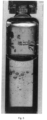
- Fig. 5 shows a syringe filled with water that has been shaken vigorously. Many air bubbles 1 of different sizes are visible here. As far as the graphic resolution of the drawing allows, it can be seen that all air bubbles 1 have the expected characteristics of a red-blue transition. Only where the obliquely incident light (red and blue) is covered by the meniscus or the stop do they appear either only red or only blue.
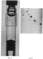
- Figs. 6a and 6b show a container 3 filled with liquid 2, wherein the liquid contains both air bubbles 1 and a glass particle 81. Since the glass particle 81 is not a sphere or hemisphere, but rather a flat splinter, the previously shown effect, according to which the Color constellation inverse to an air bubble 1 is not particularly pronounced, but nevertheless present.
- Figs. 7a and 7b show several air bubbles 1 as well as a metal particle 84 in the liquid 2 held by the container 3.
- the metal particle 84 is noticeable in that it appears completely black and does not show any coloration towards red, green or blue.
- the Figures 8a and 8b show a scratch 83 that has both red and blue sections. Without the pronounced transition from red to blue, as would have been the case with an air bubble 1, the scratch can be clearly distinguished from air bubble 1, even though the scratch 83 is significantly smaller.
- the Figures 9a and 9b show a crack 82 in the container 3 that has many branches.
- the crack 82 appears red or blue, but mostly black. It can also happen that it meets the conditions of an air bubble 1 in a very localized manner. In this case, the very small section of the larger crack 82 that meets the configuration characteristics of an air bubble 1 would be masked out. This would not result in any disadvantages for the detection of a crack 82, since it would not be the case that the entire crack 82 is masked out. Only sub-areas of the larger crack 82 are masked out.
- Fig. 10 shows various forms of air bubbles 1.
- the evaluation of the objects is of central importance. Objects with a red (green) blue transition, whose red and blue surface areas are of similar size, are to be identified with a high degree of probability as air bubbles 1 and ignored for the rest of the inspection for defects 8.
- the challenge here is to equally take into account fluctuations in the appearance of air bubbles 1, such as those shown on the right.
- the image sections are scaled, and air bubble 1 on the bottom right is by far the largest.
- the center of gravity and area are determined for the blue and red surface areas.
- the "bounding box”, i.e. the frame that encloses an object in a rectangle, may not be ideal for further calculations, as it is very dependent on the shape of the objects.
- This object-based approach causes problems, particularly with connected objects (air bubbles 1 to each other, but also air bubbles 1 at defects 8 such as scratches 83 or cracks 82). Although connected objects can be separated to a certain extent using image processing tools, this also causes defects to be fragmented and thus increases the risk that parts of defects 8 are interpreted as air bubbles 1.
- Fig. 11a shows a printed syringe with a flat meniscus. Since measuring the filling level of syringes with scales is not trivial, especially when the meniscus is very flat, as in the illustration of the Fig. 11a , the different colored lighting proves to be further advantageous.
- Fig. 11b shows a printed syringe during a rapid rotation. Since the underside of the meniscus reflects the blue light, it is clearly recognizable as such, even if the scale makes measurement difficult.
- Fig. 12 shows a container 3 which is provided with a scale having decimal separators.
- the present invention helps to avoid mistakenly perceiving such decimal separators as a particle within the liquid.
- the invention can therefore contribute to a reduction in false rejections caused by air bubbles when inspecting transparent, aqueous or viscous liquids.
- the invention can be used to search for defects in the glass container (cracks, scratches, inclusions) as well as particulate defects in the liquid.
- the invention enables a level measurement both This is possible for both printed containers and surface-treated containers. Overall, the sensitivity for the defects mentioned above is increased (through parallel light).
Landscapes
- Chemical & Material Sciences (AREA)
- General Health & Medical Sciences (AREA)
- Physics & Mathematics (AREA)
- Health & Medical Sciences (AREA)
- Life Sciences & Earth Sciences (AREA)
- Analytical Chemistry (AREA)
- Biochemistry (AREA)
- General Physics & Mathematics (AREA)
- Immunology (AREA)
- Pathology (AREA)
- Dispersion Chemistry (AREA)
- Signal Processing (AREA)
- Engineering & Computer Science (AREA)
- Investigating Materials By The Use Of Optical Means Adapted For Particular Applications (AREA)
Claims (13)
- Dispositif de détection de bulles d'air (1) dans un contenant (3) rempli de liquide (2), comprenant :une unité d'éclairage (4) destinée à irradier de lumière le contenant (3), etune unité d'enregistrement (5) destinée à enregistrer une reproduction du contenant (3) irradié par l'unité d'éclairage (4),dans lequel l'unité d'éclairage (4) comprend au moins deux sources de lumière (41, 42, 43), qui se distinguent l'une de l'autre par leur couleur de lumière spectrale et/ou leur polarisation,dans lequel le dispositif comprend en outre une unité d'évaluation (6), qui est conçue pour conclure la présence d'une bulle d'air (1) lors d'une évaluation de la reproduction de l'unité d'enregistrement (5) en raison de l'agencement spécifique des rayons de lumière émis par les sources de lumière (41, 42, 43), pouvant être distingués les uns des autres,dans lequel le contenant (3) peut être disposé entre l'unité d'éclairage (4) et l'unité d'enregistrement (5) et l'unité d'éclairage (4) et l'unité d'enregistrement (5) sont tournées l'une vers l'autre pour réaliser un éclairage par transmission du contenant (3), etdans lequel l'unité d'enregistrement (5) est positionnée de telle manièrei) que les rayons de lumière sortant des au moins deux sources de lumière (41, 42, 43) ne pénètrent pas la zone d'enregistrement de l'unité d'enregistrement (5) lors d'un passage du contenant (3), qui est exempt de bulles d'air ou d'autres particules étrangères et sont déviés en direction de l'unité d'enregistrement (5) en rencontrant une bulle d'air (1) ou une particule de verre (81), ouii) que les rayons de lumière sortant des au moins deux sources de lumière (41, 42, 43) présentent une intensité continue ou homogène dans la zone d'enregistrement de l'unité d'enregistrement (5) lors d'un passage du contenant (3), qui est exempt de bulles d'air ou d'autres particules étrangères et sont déviés en rencontrant une bulle d'air (1) ou une particule de verre (81) de telle manière qu'il en résulte une augmentation d'intensité, pouvant être détectée par l'unité d'enregistrement (5), de rayons de lumière des au moins deux sources de lumière (41, 42, 43),dans lequelles rayons de lumière des au moins deux sources de lumière (41, 42, 43) ne s'étendent pas de manière parallèle l'une par rapport à l'autre dans une zone d'inspection pour le contenant (3).
- Dispositif selon la revendication 1, dans lequel l'unité d'éclairage (4) comprend trois sources de lumière (41, 42, 43), qui se distinguent par leur couleur de lumière spectrale et/ou leur polarisation.
- Dispositif selon l'une quelconque des revendications précédentes, dans lequel l'unité d'enregistrement (5) est une caméra couleur et/ou une caméra avec un ou plusieurs filtres de polarisation.
- Dispositif selon l'une quelconque des revendications précédentes, comprenant en outre une lentille (7), qui est disposée sur le chemin optique de l'unité d'éclairage (4) vers l'unité d'enregistrement (5) et est conçue pour diriger les rayons de lumière des au moins deux sources de lumière (41, 42, 43) de l'unité d'éclairage (4) de manière parallèle à une zone d'inspection d'un contenant (3).
- Dispositif selon la revendication 4, dans lequel la lentille (7) est une lentille cylindrique, une lentille de type Fresnel et/ou une lentille cylindrique de type Fresnel.
- Dispositif selon l'une quelconque des revendications précédentes 5 ou 6, dans lequel précisément une des au moins deux sources de lumière (41, 42, 43) est disposée dans le point focal de la lentille (7) et les sources de lumière (41, 42, 43) restantes de l'unité d'éclairage (4) sont disposées de manière espacée de celle-ci sur le même côté de la lentille (7) que la source de lumière disposée dans le point focal.
- Dispositif selon l'une quelconque des revendications précédentes, dans lequel chacune des au moins deux sources de lumière (41, 42, 43) de l'unité d'éclairage (4) est une lumière linéaire, dans lequel de préférence les directions longitudinales des lumières linéaires sont parallèles les unes par rapport aux autres, ne sont toutefois pas identiques.
- Dispositif selon la revendication 7, dans lequel les lumières linéaires sont disposées de manière parallèle par rapport à un axe cylindrique d'une lentille cylindrique disposée sur le chemin optique depuis l'unité d'éclairage (4) vers l'unité d'enregistrement (5).
- Dispositif selon l'une quelconque des revendications précédentes, dans lequel une première des sources de lumière (41) a pour couleur le rouge, une deuxième des sources de lumière a pour couleur le vert (42) et une troisième des sources de lumière (43) a pour couleur le bleu.
- Dispositif selon l'une quelconque des revendications précédentes, dans lequel le contenant (3) est transparent totalement ou en partie et est de préférence une pointe, un flacon ou une ampoule.
- Dispositif selon l'une quelconque des revendications précédentes, dans lequel le liquide présent dans le contenant (3) est un liquide (2) transparent.
- Procédé de détection de bulles d'air (1) dans un contenant (3) rempli de liquide (2) avec un dispositif selon l'une quelconque des revendications précédentes, dans lequel, dans le procédé, :le contenant (3) est irradié avec une unité d'éclairage (4),une reproduction du contenant (3) irradié par l'unité d'éclairage (4) est relevée par une unité d'enregistrement (5), etla reproduction est évaluée au moyen d'une unité d'évaluation (6),dans lequel le contenant (3) est irradié par au moins deux sources de lumière (41, 42, 43) de l'unité d'éclairage (4), qui se distinguent l'une de l'autre par leur couleur de lumière spectrale et/ou leur polarisation,dans lequel les rayons de lumière sortant des au moins deux sources de lumière (41, 42, 43) ne s'étendent pas de manière parallèle les uns par rapport aux autres dans une zone d'inspection pour le contenant (3),dans lequel le contenant (3) peut être disposé entre l'unité d'éclairage (4) et l'unité d'enregistrement (5) et l'unité d'éclairage (4) et l'unité d'enregistrement (5) sont tournées l'une vers l'autre pour réaliser un éclairage par transmission du contenant (3),dans lequel les rayons de lumière partant des au moins deux sources de lumière (41, 42, 43) :i) ne pénètrent pas la zone d'enregistrement de l'unité d'enregistrement (5) et sont déviés en direction de l'unité d'enregistrement (5) en rencontrant une bulle d'air (1) ou une particule de verre (81) ouii) présentent une intensité continue ou homogène dans la zone d'enregistrement de l'unité d'enregistrement (5) et sont déviés en rencontrant une bulle d'air (1) ou une partie de verre (81) de telle manière qu'il en résulte une augmentation d'intensité pouvant être détectée par l'unité d'enregistrement (5) de rayons de lumière des au moins deux sources de lumière (41, 42, 43)lors du passage du contenant (3), qui est exempt de bulles d'air ou d'autres particules étrangères,et dans lequel l'agencement spécifique de rayons de lumière émis par les sources de lumière (41, 42, 43), pouvant être distingués les uns des autres permet de conclure la présence d'une bulle d'air (1) lors de l'évaluation de la reproduction au moyen de l'unité d'évaluation (6).
- Procédé selon la revendication 12, dans lequel on conclut la présence d'une bulle d'air (1) lorsque la reproduction reflète un agencement spécifique des rayons de lumière émis par les sources de lumière (41, 42, 43), pouvant être distingués les uns des autres, qui correspond à l'ordre d'agencement réel d'un sous-groupe des sources de lumière (41, 42, 43) ou de toutes les sources de lumière (41, 42, 43) dans l'unité d'éclairage (4).
Applications Claiming Priority (1)
| Application Number | Priority Date | Filing Date | Title |
|---|---|---|---|
| DE102016012585.3A DE102016012585A1 (de) | 2016-10-21 | 2016-10-21 | Vorrichtung zur Detektion von Luftblasen in einem mit Flüssigkeit befüllten Behälter |
Publications (3)
| Publication Number | Publication Date |
|---|---|
| EP3312592A1 EP3312592A1 (fr) | 2018-04-25 |
| EP3312592C0 EP3312592C0 (fr) | 2024-10-02 |
| EP3312592B1 true EP3312592B1 (fr) | 2024-10-02 |
Family
ID=59506191
Family Applications (1)
| Application Number | Title | Priority Date | Filing Date |
|---|---|---|---|
| EP17184327.9A Active EP3312592B1 (fr) | 2016-10-21 | 2017-08-01 | Dispositif et procédé de détection de bulles d'air dans un récipient rempli de liquide |
Country Status (3)
| Country | Link |
|---|---|
| EP (1) | EP3312592B1 (fr) |
| DE (1) | DE102016012585A1 (fr) |
| ES (1) | ES2989703T3 (fr) |
Families Citing this family (9)
| Publication number | Priority date | Publication date | Assignee | Title |
|---|---|---|---|---|
| DE102019205653A1 (de) * | 2019-04-18 | 2020-10-22 | Krones Ag | Durchlichtinspektionsvorrichtung und Durchlichtinspektionsverfahren zur Seitenwandinspektion von Behältern |
| DE102019205654A1 (de) * | 2019-04-18 | 2020-10-22 | Krones Ag | Durchlichtinspektionsvorrichtung und -verfahren zur Inspektion von Behältern |
| DE102019208299A1 (de) * | 2019-06-06 | 2020-12-10 | Krones Ag | Verfahren und Vorrichtung zur optischen Inspektion von Behältern |
| DE102019208296A1 (de) * | 2019-06-06 | 2020-12-10 | Krones Ag | Verfahren und Vorrichtung zur optischen Inspektion von Behältern |
| DE102019117260A1 (de) | 2019-06-26 | 2020-12-31 | Seidenader Maschinenbau Gmbh | Vorrichtung zur optischen Inspektion von leeren und mit Flüssigkeit gefüllten Behältern |
| CN112525920B (zh) * | 2020-11-23 | 2023-03-10 | 山东科技大学 | 一种液体透视成像干扰滤波系统 |
| GB2609969B (en) | 2021-08-19 | 2024-07-10 | Ash Tech Limited | System and method for inspecting an object |
| US12170849B2 (en) | 2022-02-04 | 2024-12-17 | Applied Materials, Inc. | Pulsed illumination for fluid inspection |
| FR3144665A1 (fr) * | 2022-12-29 | 2024-07-05 | Tiama | Dispositif et procédé d’analyse d’un relief d’inspection d’une paroi d’un récipient en verre |
Citations (1)
| Publication number | Priority date | Publication date | Assignee | Title |
|---|---|---|---|---|
| DE102010012570A1 (de) * | 2010-03-23 | 2011-09-29 | Krones Ag | Vorrichtung und Verfahren zum Untersuchen von befüllten Behältnissen auf Fremdkörper |
Family Cites Families (7)
| Publication number | Priority date | Publication date | Assignee | Title |
|---|---|---|---|---|
| NL8902916A (nl) * | 1989-11-24 | 1991-06-17 | Heuft Qualiplus Bv | Inspectie-inrichting op basis van donkerveld-belichting. |
| CH681748A5 (en) * | 1990-10-30 | 1993-05-14 | Eisai Co Ltd | Optical sorting device for filled glass ampoules beams - uses 2 intersecting light beams with evaluation of both transmitted and reflected light components. |
| DE19949029C2 (de) * | 1999-10-11 | 2002-11-21 | Innovatis Gmbh | Verfahren und Vorrichtung zur Charakterisierung einer Kulturflüssigkeit |
| CN101528288A (zh) * | 2006-10-24 | 2009-09-09 | 马林克罗特公司 | 光学夹杂物传感器 |
| DE102012205311B4 (de) * | 2012-03-30 | 2013-10-17 | Anton Paar Gmbh | Optische Vorrichtung, insbesondere Polarimeter, zur Detektion von Inhomogenitäten in einer Probe |
| US10132736B2 (en) * | 2012-05-24 | 2018-11-20 | Abbvie Inc. | Methods for inspection of protein particles in a liquid beneficial agent |
| DE102014006496A1 (de) * | 2014-05-06 | 2015-11-12 | Balluff STM GmbH | Verfahren und Sensor zur Fluid-Erkennung in transparenten Schläuchen |
-
2016
- 2016-10-21 DE DE102016012585.3A patent/DE102016012585A1/de active Pending
-
2017
- 2017-08-01 EP EP17184327.9A patent/EP3312592B1/fr active Active
- 2017-08-01 ES ES17184327T patent/ES2989703T3/es active Active
Patent Citations (1)
| Publication number | Priority date | Publication date | Assignee | Title |
|---|---|---|---|---|
| DE102010012570A1 (de) * | 2010-03-23 | 2011-09-29 | Krones Ag | Vorrichtung und Verfahren zum Untersuchen von befüllten Behältnissen auf Fremdkörper |
Also Published As
| Publication number | Publication date |
|---|---|
| EP3312592A1 (fr) | 2018-04-25 |
| ES2989703T3 (es) | 2024-11-27 |
| DE102016012585A1 (de) | 2018-04-26 |
| EP3312592C0 (fr) | 2024-10-02 |
Similar Documents
| Publication | Publication Date | Title |
|---|---|---|
| EP3312592A1 (fr) | Procédé de détection de bulles d'air dans un récipient rempli de liquide | |
| DE60223956T3 (de) | Untersuchungsgerät und System zur Untersuchung von Fremdkörpern in mit Flüssigkeit gefüllten Behältern | |
| DE102010012570B4 (de) | Vorrichtung und Verfahren zum Untersuchen von befüllten Behältnissen auf Fremdkörper | |
| DE69525195T2 (de) | Optische Inspektion von Dimensionsparametern von Behältern | |
| EP3204759B1 (fr) | Dispositif d'inspection et procédé d'inspection en lumière transmise de récipients | |
| DE102012009783B3 (de) | Verfahren und Vorrichtung zur Inspektion von Leerflaschen | |
| DE19741384A1 (de) | Verfahren zum Erkennen von diffus streuenden Materialien, Verunreinigungen und sonstigen Fehlern bei transparenten Gegenständen | |
| DE69419277T2 (de) | Gerät für die Untersuchung eines Bodenrandbereiches eines transparenten Glasbehälters | |
| DE102009039254A1 (de) | Vorrichtung und Verfahren zum Inspizieren etikettierter Gefäße | |
| EP3180135A1 (fr) | Procédé d'inspection optique et dispositif d'inspection optique de récipients | |
| EP0927348B1 (fr) | Procede et dispositif pour controler automatiquement par voie optique la qualite de produits plats et lisses | |
| DE102014217771A1 (de) | Vorrichtung und Verfahren zur Qualitätskontrolle transparenter Objekte | |
| WO2021213779A1 (fr) | Procédé et dispositif d'inspection optique de récipients dans un système de traitement de boissons | |
| WO2020244817A1 (fr) | Procédé et dispositif d'inspection optique de contenants | |
| WO2020244815A1 (fr) | Procédé et dispositif d'inspection optique de contenants | |
| DE102009039612A1 (de) | Verfahren und Vorrichtung zur Durchlichtinspektion von Behältern | |
| WO2020244818A1 (fr) | Procédé et dispositif d'inspection optique de contenants | |
| DE102014107915A1 (de) | Inspektionsvorrichtung für Behälterverschlüsse | |
| DE102007054657A1 (de) | Optische Erfassungseinrichtung, insbesondere zur Inspektion von Flaschen, sowie entsprechendes Visualisierungsverfahren | |
| WO2011098324A1 (fr) | Procédé et dispositif de contrôle de surface par déflectométrie | |
| DE102018105060B3 (de) | System zur Überwachung der Qualität einer Klebstoffspur | |
| DE102008018096B4 (de) | Vorrichtung zum Untersuchen von Oberflächeneigenschaften von Behältnissen | |
| EP2671649B2 (fr) | Dispositif d'identification d'une bouteille | |
| WO2020008077A1 (fr) | Procédé et dispositif de contrôle optique de préformes | |
| DE69008676T2 (de) | Inspektionsgerät mit Dunkelfeldbeleuchtung. |
Legal Events
| Date | Code | Title | Description |
|---|---|---|---|
| PUAI | Public reference made under article 153(3) epc to a published international application that has entered the european phase |
Free format text: ORIGINAL CODE: 0009012 |
|
| STAA | Information on the status of an ep patent application or granted ep patent |
Free format text: STATUS: THE APPLICATION HAS BEEN PUBLISHED |
|
| AK | Designated contracting states |
Kind code of ref document: A1 Designated state(s): AL AT BE BG CH CY CZ DE DK EE ES FI FR GB GR HR HU IE IS IT LI LT LU LV MC MK MT NL NO PL PT RO RS SE SI SK SM TR |
|
| AX | Request for extension of the european patent |
Extension state: BA ME |
|
| STAA | Information on the status of an ep patent application or granted ep patent |
Free format text: STATUS: REQUEST FOR EXAMINATION WAS MADE |
|
| 17P | Request for examination filed |
Effective date: 20180606 |
|
| STAA | Information on the status of an ep patent application or granted ep patent |
Free format text: STATUS: EXAMINATION IS IN PROGRESS |
|
| 17Q | First examination report despatched |
Effective date: 20200311 |
|
| RAP3 | Party data changed (applicant data changed or rights of an application transferred) |
Owner name: KOERBER PHARMA INSPECTION GMBH |
|
| TPAC | Observations filed by third parties |
Free format text: ORIGINAL CODE: EPIDOSNTIPA |
|
| REG | Reference to a national code |
Ref country code: DE Ref legal event code: R079 Free format text: PREVIOUS MAIN CLASS: G01N0021510000 Ipc: G01N0021900000 Ref country code: DE Ref legal event code: R079 Ref document number: 502017016457 Country of ref document: DE Free format text: PREVIOUS MAIN CLASS: G01N0021510000 Ipc: G01N0021900000 |
|
| GRAP | Despatch of communication of intention to grant a patent |
Free format text: ORIGINAL CODE: EPIDOSNIGR1 |
|
| STAA | Information on the status of an ep patent application or granted ep patent |
Free format text: STATUS: GRANT OF PATENT IS INTENDED |
|
| RIC1 | Information provided on ipc code assigned before grant |
Ipc: G01N 15/14 20060101ALN20240415BHEP Ipc: G01N 15/00 20060101ALN20240415BHEP Ipc: G01N 15/1434 20240101ALI20240415BHEP Ipc: G01N 15/1433 20240101ALI20240415BHEP Ipc: G01N 21/21 20060101ALI20240415BHEP Ipc: G01N 21/51 20060101ALI20240415BHEP Ipc: G01N 21/88 20060101ALI20240415BHEP Ipc: G01N 21/90 20060101AFI20240415BHEP |
|
| INTG | Intention to grant announced |
Effective date: 20240429 |
|
| GRAS | Grant fee paid |
Free format text: ORIGINAL CODE: EPIDOSNIGR3 |
|
| GRAA | (expected) grant |
Free format text: ORIGINAL CODE: 0009210 |
|
| STAA | Information on the status of an ep patent application or granted ep patent |
Free format text: STATUS: THE PATENT HAS BEEN GRANTED |
|
| AK | Designated contracting states |
Kind code of ref document: B1 Designated state(s): AL AT BE BG CH CY CZ DE DK EE ES FI FR GB GR HR HU IE IS IT LI LT LU LV MC MK MT NL NO PL PT RO RS SE SI SK SM TR |
|
| REG | Reference to a national code |
Ref country code: GB Ref legal event code: FG4D Free format text: NOT ENGLISH |
|
| REG | Reference to a national code |
Ref country code: CH Ref legal event code: EP |
|
| REG | Reference to a national code |
Ref country code: IE Ref legal event code: FG4D Free format text: LANGUAGE OF EP DOCUMENT: GERMAN |
|
| REG | Reference to a national code |
Ref country code: DE Ref legal event code: R096 Ref document number: 502017016457 Country of ref document: DE |
|
| U01 | Request for unitary effect filed |
Effective date: 20241002 |
|
| U07 | Unitary effect registered |
Designated state(s): AT BE BG DE DK EE FI FR IT LT LU LV MT NL PT RO SE SI Effective date: 20241009 |
|
| REG | Reference to a national code |
Ref country code: ES Ref legal event code: FG2A Ref document number: 2989703 Country of ref document: ES Kind code of ref document: T3 Effective date: 20241127 |
|
| PG25 | Lapsed in a contracting state [announced via postgrant information from national office to epo] |
Ref country code: IS Free format text: LAPSE BECAUSE OF FAILURE TO SUBMIT A TRANSLATION OF THE DESCRIPTION OR TO PAY THE FEE WITHIN THE PRESCRIBED TIME-LIMIT Effective date: 20250202 Ref country code: HR Free format text: LAPSE BECAUSE OF FAILURE TO SUBMIT A TRANSLATION OF THE DESCRIPTION OR TO PAY THE FEE WITHIN THE PRESCRIBED TIME-LIMIT Effective date: 20241002 |
|
| PG25 | Lapsed in a contracting state [announced via postgrant information from national office to epo] |
Ref country code: NO Free format text: LAPSE BECAUSE OF FAILURE TO SUBMIT A TRANSLATION OF THE DESCRIPTION OR TO PAY THE FEE WITHIN THE PRESCRIBED TIME-LIMIT Effective date: 20250102 |
|
| PG25 | Lapsed in a contracting state [announced via postgrant information from national office to epo] |
Ref country code: GR Free format text: LAPSE BECAUSE OF FAILURE TO SUBMIT A TRANSLATION OF THE DESCRIPTION OR TO PAY THE FEE WITHIN THE PRESCRIBED TIME-LIMIT Effective date: 20250103 |
|
| PG25 | Lapsed in a contracting state [announced via postgrant information from national office to epo] |
Ref country code: PL Free format text: LAPSE BECAUSE OF FAILURE TO SUBMIT A TRANSLATION OF THE DESCRIPTION OR TO PAY THE FEE WITHIN THE PRESCRIBED TIME-LIMIT Effective date: 20241002 Ref country code: CZ Free format text: LAPSE BECAUSE OF FAILURE TO SUBMIT A TRANSLATION OF THE DESCRIPTION OR TO PAY THE FEE WITHIN THE PRESCRIBED TIME-LIMIT Effective date: 20241002 |
|
| PG25 | Lapsed in a contracting state [announced via postgrant information from national office to epo] |
Ref country code: RS Free format text: LAPSE BECAUSE OF FAILURE TO SUBMIT A TRANSLATION OF THE DESCRIPTION OR TO PAY THE FEE WITHIN THE PRESCRIBED TIME-LIMIT Effective date: 20250102 |
|
| PG25 | Lapsed in a contracting state [announced via postgrant information from national office to epo] |
Ref country code: SM Free format text: LAPSE BECAUSE OF FAILURE TO SUBMIT A TRANSLATION OF THE DESCRIPTION OR TO PAY THE FEE WITHIN THE PRESCRIBED TIME-LIMIT Effective date: 20241002 |
|
| PG25 | Lapsed in a contracting state [announced via postgrant information from national office to epo] |
Ref country code: SK Free format text: LAPSE BECAUSE OF FAILURE TO SUBMIT A TRANSLATION OF THE DESCRIPTION OR TO PAY THE FEE WITHIN THE PRESCRIBED TIME-LIMIT Effective date: 20241002 |
|
| PLBE | No opposition filed within time limit |
Free format text: ORIGINAL CODE: 0009261 |
|
| STAA | Information on the status of an ep patent application or granted ep patent |
Free format text: STATUS: NO OPPOSITION FILED WITHIN TIME LIMIT |
|
| 26N | No opposition filed |
Effective date: 20250703 |
|
| U20 | Renewal fee for the european patent with unitary effect paid |
Year of fee payment: 9 Effective date: 20250827 |
|
| PGFP | Annual fee paid to national office [announced via postgrant information from national office to epo] |
Ref country code: ES Payment date: 20250902 Year of fee payment: 9 |
|
| PGFP | Annual fee paid to national office [announced via postgrant information from national office to epo] |
Ref country code: CH Payment date: 20250901 Year of fee payment: 9 |
|
| PGFP | Annual fee paid to national office [announced via postgrant information from national office to epo] |
Ref country code: IE Payment date: 20250824 Year of fee payment: 9 |
|
| U1N | Appointed representative for the unitary patent procedure changed after the registration of the unitary effect |
Representative=s name: LORENZ SEIDLER GOSSEL PART. MBB; DE |
|
| PG25 | Lapsed in a contracting state [announced via postgrant information from national office to epo] |
Ref country code: MC Free format text: LAPSE BECAUSE OF FAILURE TO SUBMIT A TRANSLATION OF THE DESCRIPTION OR TO PAY THE FEE WITHIN THE PRESCRIBED TIME-LIMIT Effective date: 20241002 |
|
| GBPC | Gb: european patent ceased through non-payment of renewal fee |
Effective date: 20250801 |