EP3312641A1 - Procédé, appareil et système de balayage et d'imagerie - Google Patents
Procédé, appareil et système de balayage et d'imagerie Download PDFInfo
- Publication number
- EP3312641A1 EP3312641A1 EP17197099.9A EP17197099A EP3312641A1 EP 3312641 A1 EP3312641 A1 EP 3312641A1 EP 17197099 A EP17197099 A EP 17197099A EP 3312641 A1 EP3312641 A1 EP 3312641A1
- Authority
- EP
- European Patent Office
- Prior art keywords
- inspection
- displacement
- predetermined displacement
- designated position
- imaging
- Prior art date
- Legal status (The legal status is an assumption and is not a legal conclusion. Google has not performed a legal analysis and makes no representation as to the accuracy of the status listed.)
- Granted
Links
Images



Classifications
-
- G—PHYSICS
- G01—MEASURING; TESTING
- G01V—GEOPHYSICS; GRAVITATIONAL MEASUREMENTS; DETECTING MASSES OR OBJECTS; TAGS
- G01V5/00—Prospecting or detecting by the use of ionising radiation, e.g. of natural or induced radioactivity
- G01V5/20—Detecting prohibited goods, e.g. weapons, explosives, hazardous substances, contraband or smuggled objects
- G01V5/22—Active interrogation, i.e. by irradiating objects or goods using external radiation sources, e.g. using gamma rays or cosmic rays
- G01V5/223—Mixed interrogation beams, e.g. using more than one type of radiation beam
-
- G—PHYSICS
- G01—MEASURING; TESTING
- G01N—INVESTIGATING OR ANALYSING MATERIALS BY DETERMINING THEIR CHEMICAL OR PHYSICAL PROPERTIES
- G01N23/00—Investigating or analysing materials by the use of wave or particle radiation, e.g. X-rays or neutrons, not covered by groups G01N3/00 – G01N17/00, G01N21/00 or G01N22/00
- G01N23/02—Investigating or analysing materials by the use of wave or particle radiation, e.g. X-rays or neutrons, not covered by groups G01N3/00 – G01N17/00, G01N21/00 or G01N22/00 by transmitting the radiation through the material
- G01N23/06—Investigating or analysing materials by the use of wave or particle radiation, e.g. X-rays or neutrons, not covered by groups G01N3/00 – G01N17/00, G01N21/00 or G01N22/00 by transmitting the radiation through the material and measuring the absorption
- G01N23/10—Investigating or analysing materials by the use of wave or particle radiation, e.g. X-rays or neutrons, not covered by groups G01N3/00 – G01N17/00, G01N21/00 or G01N22/00 by transmitting the radiation through the material and measuring the absorption the material being confined in a container, e.g. in a luggage X-ray scanners
Definitions
- the present disclosure relates to imaging techniques, and more particularly to a method, an apparatus, and a system for scanning and imaging.
- X-ray imaging inspection technology is a widely used security inspection technology, and a lot of equipments based on X-ray imaging inspection technology can be seen at the airport, the railway station.
- neutron inspection technology Another existing dangerous goods inspection technology is neutron inspection technology.
- the neutron can react with the nucleus of the substance and release the characteristic ⁇ -ray. According to the energy spectrum of the ⁇ -ray, the element type of the substance to be analyzed can be determined.
- neutron-X-ray contraband inspection method capable of combining the X-ray imaging inspection techniques and the neutron inspection techniques described above to obtain these advantages of high resolution of the X-ray imaging inspection technique and element recognition ability of the neutron inspection technique.
- the basic idea is to merge the neutron image and the X-ray image into an images so that the point corresponding to the same position of the inspected object in the neutron image and the X-ray image are completely coincident.
- each of the points includes the element distribution information and the density information of the object being inspected.
- An image produced by the neutron imaging technique is made of a certain number of columns, and an image produced by the x-ray imaging technique is made of a certain number of columns.
- the existing neutron and X-ray image fusion method is that the number difference of image columns between the scanned images formed by the two kinds of radiation source is obtained by calculation according to the fixed distance between the two kinds of radiation inspection devices and constant speed. Two identical scanned images of the same number of columns are obtained after a subtraction operation, and then they are merged.
- a method of image fusion is actually disadvantageous in the fact that, in the actual situation, the scanning speed of the system is not constant, and the scanned image formed after the image fusion cannot be completely merged, and there is a shadowed part. This will affect the performance of the equipment, and the scanned images of the object cannot be clearly and accurately shown.
- the present disclosure provides a method, apparatus and system for scanning and imaging capable of enhancing the performance of equipments and clearly and accurately displaying a scanned image of an object.
- a method for scanning and imaging comprising: generating first inspection data correspondingly according to a first predetermined displacement of the object to be inspected by a first inspection device; generating second inspection data correspondingly according to a second predetermined displacement of the object by a second inspection device; converting the first inspection data into a first scanned image; converting the second inspection data into a second scanned image; and merging the first scanned image and the second scanned image.
- the first inspection device Because the first inspection device generates first inspection data correspondingly with the first predetermined displacement of the object, there is a relationship between the inspection data generated by the first inspection device and the spatial dimension of the object. Because the second inspection device generates second inspection data correspondingly with the second predetermined displacement of the object, there is a relationship between the inspection data generated by the second inspection device and the spatial dimension of the object. Accurate merging of the first and second scanned images is thereby facilitated.
- the first predetermined displacement is equal to the second predetermined displacement.
- the number of columns in the first scanned image is the same as the number of columns in the second scanned image. Thereby, merging of the first and second scanned images is simplified.
- the method further comprises: generating a displacement signal by a displacement sensor.
- the displacement sensor is a rotary encoder.
- the method further comprises: starting to generate a first trigger signal for the first inspection device based on the first predetermined displacement when the object reaches a first designated position.
- the method further comprises: stopping the transmission of the first trigger signal when the object leaves a third designated position.
- the method further comprises: starting to generate a second trigger signal for the second inspection device based on the second predetermined displacement when the object reaches a second designated position.
- the method further comprises: stopping the transmission of the second trigger signal when the object leaves a fourth designated position.
- the first inspection data and the second inspection data are column data.
- an apparatus for scanning and imaging comprising: a first inspection module for generating first inspection data correspondingly according to a first predetermined displacement of the object to be inspected; second inspection module for generating second inspection data correspondingly according to a second predetermined displacement of the object; and an imaging module for converting the first inspection data into a first scanned image, converting the second inspection data into a second scanned image, and merging the first scanned image and the second scanned image.
- the above apparatus further comprises: a displacement module for generating a first displacement signal and a second displacement signal based on the object movement information.
- the apparatus further comprises: a control module for acquiring the first predetermined displacement and the second predetermined displacement of the object; starting to generate a first trigger signal for the first inspection device based on the first predetermined displacement when the object reaches the first designated position and has not left a third designated position; and starting to generate a second trigger signal for the second inspection device based on the second predetermined displacement when the object reaches the second designated position and has not left a fourth designated position.
- a system for scanning and imaging comprising: an encoder for obtaining displacement information of the object to be inspected; a controller for controlling the inspection of the inspection device based on the displacement information of the object; a inspection device for inspecting the object, and collecting the inspection data; an imaging system for processing the inspection data to image the object; and a conveyor for transporting the object.
- the method for scanning and imaging of the present invention it is possible to improve the performance of the equipment and to clearly and accurately exhibit the image of the object by solving the problem of mismatching when several kinds of ray images are merged.
- FIG.1 is a block diagram of a system for scanning and imaging shown in accordance with an exemplary embodiment.
- the system 10 for scanning and imaging includes a conveyor 101, an encoder 103, a controller 105, at least two inspection devices 107, and an imaging device 109.
- the original image merging method is based on calculation according to the fixed distance between the two kinds of radiation inspection devices and constant speed, that is, it is not accurate to use the constant speed to calculate the number of columns of the two image phases.
- the present disclosure controls the relationship between the moving distance of the scanned goods and the number of columns of the scanned image so that the ray inspection device produces a fixed number of scanning columns whenever the object to be inspected is moved for a unit distance, and finally the resulting number of columns of the scanned images is only related to the length of the object itself.
- the conveyor 101 is a device for carrying and transmitting the object to be inspected, and the object is relatively fixed to the transmission system during transmission.
- the encoder 103 is a device for acquiring the displacement information of the object to be inspected.
- the encoder rotates as the object moves on the conveyor, and generates a signal when it is rotated. Since there is no relative displacement between the object and the conveyor, the number of signals produced for each distance the object moves is a fixed number.
- the controller 105 is a device for controlling the inspection device.
- the controller reads the pulses transmitted by the encoder, calculates the pulse displacement into the displacement quantity, then generates the corresponding control signal, and controls the inspection device to generate the radiation.
- the inspection device 107 is a device for generating inspection rays and collecting the inspection data, and complete scan data of the radiography can be obtained when the object to be inspected passes through any one of the inspection devices.
- the imaging device 109 is a device for receiving scan data from the inspection device and converting the data into an image.
- the object to be inspected sequentially passes through two inspection devices to complete a scan process, and the imaging device merges the images obtained by the scanning of the two inspection devices to generate the final image.
- the communication connection among the conveyor 101, the encoder 103, the controller 105, the inspection device 107, and the imaging device 109 may be a wired connection or a wireless connection, and is not limited herein.
- system 10 for scanning and imaging is merely illustrative and not restrictive of the present disclosure.
- FIG.2 is a flow chart of a method for scanning and imaging shown in accordance with an exemplary embodiment.
- FIG.2 is a flow diagram of a method for scanning and imaging shown in accordance with an exemplary embodiment. The method can be applied to the system shown in Fig. 1 . As shown in FIG.2 , the method 20 comprises the following steps.
- step S201 first inspection data is generated correspondingly according to a first predetermined displacement of the object to be inspected by a first inspection device.
- the controller calculates a first predetermined displacement based on the system setting, generates a corresponding control signal based on the first predetermined displacement, and controls the first inspection device to detect and collect the inspection data.
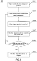
- FIG.3 shows specific steps and information.
- a displacement signal is generated by a displacement sensor, which is a rotary encoder and can be a "Beckhoff incremental encoder” and the like.
- the encoder rotates as the object moves on the conveyor and generates a signal when it rotates. A certain number of pulse signals are generated for each distance the object moves. Since there is no relative displacement between the object and the conveyor, the number of signals produced for each distance the object moves is a fixed number.
- the first inspection device may be an X-ray inspection device.
- step S203 second inspection data is generated correspondingly according to a second predetermined displacement of the object by a second inspection device.
- the controller calculates a second predetermined displacement based on the system settings, generates a corresponding control signal based on the second predetermined displacement, and controls the second inspection device to detect and collect the inspection data.
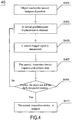
- FIG.4 shows specific steps and information.
- the second inspection device may be a neutron beam inspection device.
- the first predetermined displacement may be equal to the second predetermined displacement.
- the first predetermined displacement and the second predetermined displacement are both W, wherein W is a preset value in the system. That is, an inspection operation is performed for each W distance the object moves in the first inspection device inspection interval (between the first designated position and the third designated position), and an inspection operation is also performed for each W distance the object moves in the second inspection device inspection interval (between the third designated position and the fourth designated position).
- step S205 the first inspection data is converted into a first scanned image.
- the first inspection data inspected and acquired in the first inspection operation is used as a first column of a first scanned image.
- the first inspection data obtained by scanning is sequentially arranged, and the first ray data acquired in the nth time is used as the nth column of the first scanned image, wherein n is a positive integer greater than or equal to one.
- step S207 the second inspection data is converted into a second scanned image.
- the second inspection data inspected and acquired in the first inspection operation is used as the first column of the second scanned image.
- the second inspected data obtained by scanning is sequentially arranged, and the first ray data acquired in the mth inspection operation is used as the mth column of the second scanned image, wherein m is a positive integer greater than or equal to one.
- step S209 the first scanned image and the second scanned image are merged.
- a set of complete inspection data is obtained, and a scanned image of the object is obtained after the data is sent to the imaging device. Similarly, a scanned image of the object is also obtained after the object passes through the second inspection device.
- the first scanned image and the second scanned image can be directly merged.
- the method for scanning and imaging of the present embodiment of the present invention overcomes the problem of inconsistency in the number of columns of the scanning images in the scanning process because of the speed changes.
- the problem of mismatching when merging multiple images can be effectively solved, and thus the use performance of the product is improved and the competitiveness of the product is increased.
- FIG.3 is a flow chart of another method for scanning and imaging shown in accordance with an exemplary embodiment. This figure illustrates a specific method for obtaining the first inspection data, which can be applied to the system shown in Fig. 1 or as a supplement to the method described in Fig. 2 . As shown in FIG.3 , the method 30 comprises the following steps.
- step S301 the object reaches the first designated position.
- the object is conveyed on the conveyor, and its position is determined by the sensor so as to determine whether the object has reached the first designated position.
- the first designated position is a preset value, which can be set in the initial settings of the system, and subsequently be adjusted according to the actual situation during the use process of the system for scanning and imaging.
- the first designated position is located at the point A cm before the object passes through the first inspection device. The arrival of the object at the first designated position means that any side or any face of the object reaches the first designated position.
- step S303 a first predetermined displacement signal is generated.
- the controller continuously receives the pulse signal from the encoder during the operation of the entire system.
- a first predetermined displacement is generated according to the system settings. For example, a first displacement signal is generated for every p pulse signals, wherein p is a positive integer greater than or equal to one.
- the controller calculates the number of pulses obtained, and thus obtains the first predetermined displacement.
- step S305 the first trigger signal is transmitted.
- the controller After the controller has calculated and obtained the first predetermined displacement, the controller then generates the first trigger signal and sends the signal to the first inspection device.
- step S307 the first inspection device detects and collects data.
- the first inspection device After the first inspection device receives the first trigger signal, the object to be inspected is being inspected, and the first inspection data is collected and transmitted to the imaging device.
- step S309 it is determined whether the object has left the third designated position.
- the position of the object is continued to be determined by the sensor to determine whether or not the object has left the third designated position.
- the third designated position is a pre-set value, which can be set in the initial settings of the system, and subsequently be adjusted according to the actual situation during the use process of the system for scanning and imaging.
- the third designated position is located at the point B cm after the object passes through the first inspection device. The departure of the object at the third designated position means that all sides or all faces of the object have left the third designated position.
- step S311 is performed.
- step S311 the first inspection device is stopped.
- the object completely leaves the third designated position, i.e. it represents that the object leaves the inspection space of the first inspection device and the first inspection device stops working.
- FIG.4 is a flow chart of another method for scanning and imaging shown in accordance with an exemplary embodiment. This method illustrates a specific method for obtaining the second inspection data, which can be applied to the system shown in Fig. 1 or as a supplement to the method described in FIG. 2 . As shown in FIG.4 , the method 40 comprises the steps as described as follows.
- step S401 the object reaches the second designated position.
- the object is conveyed on the conveyor, and its position is determined by the sensor to determine whether the object has reached the second designated position.
- the second designated position is a preset value, which can be set in the initial settings of the system, and subsequently be adjusted according to the actual situation during the use process of the system for scanning and imaging.
- the second designated position is located at the point C cm before the object passes through the second inspection device. The arrival of the object at the second designated position has the meaning that any side or any face of the object reaches the second designated position.
- step S403 a second predetermined displacement is obtained.
- the controller continuously receives the pulse signal from the encoder during the operation of the entire system.
- a second predetermined displacement is generated according to the system setting, for example, a second displacement signal is generated for every q pulse signal, and q is a positive integer greater than or equal to one.
- the controller calculates to obtain the number of pulses, and thus obtains the second predetermined displacement.
- step S405 the second trigger signal is transmitted.
- the controller After the controller has calculated and obtained the second predetermined displacement, the controller then generates the second trigger signal and sends the signal to the second inspection device.
- step S407 the second inspection device detects and collects data.
- the second inspection device After the second inspection device receives the second trigger signal, the object to be inspected is being inspected, and the second inspection data is collected and transmitted to the imaging device.
- step S409 it is determined whether or not the object has left the forth designated position.
- the position of the object is continued to be determined by the sensor so as to determine whether or not the object leaves the fourth designated position.
- the fourth designated position is a preset value, which can be set in the initial settings of the system, and subsequently be adjusted according to the actual situation during the use process of the system for scanning and imaging.
- the fourth designated position is located at the point D cm after the object passes through the second inspection device. The departure of the object at the fourth designated position has the meaning that all sides or all faces of the object have left the fourth designated position.
- step 4311 is performed.
- step S411 the second inspection device is stopped.
- the object completely leaves the fourth designated position, i.e. it represents that the object leaves inspection space of the second inspection device and the second inspection device stops working.
- the program may be stored in a computer-readable storage medium, which may be a read-only memory, a magnetic disk, an optical disk, or the like.
- FIG.5 is a block diagram of yet another apparatus for scanning and imaging shown in accordance with an exemplary embodiment.
- the apparatus 50 includes a displacement module 501, a control module 503, a first inspection module 505, a second inspection module 507, and an imaging module 509.
- the displacement module 501 is used to generate a first displacement signal and a second displacement signal based on the object movement information.
- the control module 503 is used to acquire the first predetermined displacement information and the second predetermined displacement information of the object; begins to generate a first trigger signal for the first inspection device based on the first predetermined displacement signal when the object reaches a first designated position; and begins to generate a second trigger signal for the second inspection device based on the second predetermined displacement signal when the object reaches a second designated position.
- the first inspection module 505 generates the first inspection data correspondingly according to the first predetermined displacement of the object.
- the second inspection module 507 generates the second inspection data correspondingly according to the second predetermined displacement of the object.
- the imaging module 509 is used to convert the first ray data into a first scanned image, convert the second ray data into a second scanned image, and merge the first scanned image and the second scanned image.
- the apparatus for scanning and imaging in the embodiments of the present invention overcomes the problem of inconsistency in the number of columns of the scanning images in the scanning process because of the speed changes.
- the problem of mismatching when merging multiple images can be effectively solved to improve the use performance of the product and increase the competitiveness of the product.
- block diagram shown in the above figures is a functional entity and does not necessarily have to correspond to a physically or logically independent entity.
- These functional entities may be implemented in software form or implemented in one or more hardware modules or integrated circuits, or these functional entities are implemented in different networks and/or processor devices and/or micro-controllers.
- the exemplary embodiments described herein may be implemented by software or by means of software in conjunction with the necessary hardware.
- the technical solution according to the embodiments of the present disclosure may be embodied in the form of a software product which may be stored on a nonvolatile storage medium (which may be a CD-ROM, a U disk, a mobile hard disk, etc.) or on a network, comprising a number of instructions to enable a computing device (which may be a personal computer, a server, a mobile terminal, or a network device, etc.) to perform a method according to an embodiment of the present disclosure.
- a nonvolatile storage medium which may be a CD-ROM, a U disk, a mobile hard disk, etc.
- a network comprising a number of instructions to enable a computing device (which may be a personal computer, a server, a mobile terminal, or a network device, etc.) to perform a method according to an embodiment of the present disclosure.
Landscapes
- Physics & Mathematics (AREA)
- General Physics & Mathematics (AREA)
- Life Sciences & Earth Sciences (AREA)
- Immunology (AREA)
- Analytical Chemistry (AREA)
- Biochemistry (AREA)
- General Health & Medical Sciences (AREA)
- Chemical & Material Sciences (AREA)
- Health & Medical Sciences (AREA)
- Pathology (AREA)
- High Energy & Nuclear Physics (AREA)
- General Life Sciences & Earth Sciences (AREA)
- Geophysics (AREA)
- Analysing Materials By The Use Of Radiation (AREA)
- Investigating Or Analysing Materials By Optical Means (AREA)
- Geophysics And Detection Of Objects (AREA)
Applications Claiming Priority (1)
| Application Number | Priority Date | Filing Date | Title |
|---|---|---|---|
| CN201610909414.5A CN106290423B (zh) | 2016-10-18 | 2016-10-18 | 用于扫描成像的方法、装置以及系统 |
Publications (2)
| Publication Number | Publication Date |
|---|---|
| EP3312641A1 true EP3312641A1 (fr) | 2018-04-25 |
| EP3312641B1 EP3312641B1 (fr) | 2021-02-24 |
Family
ID=57719361
Family Applications (1)
| Application Number | Title | Priority Date | Filing Date |
|---|---|---|---|
| EP17197099.9A Not-in-force EP3312641B1 (fr) | 2016-10-18 | 2017-10-18 | Procédé, appareil et système de balayage et d'imagerie |
Country Status (4)
| Country | Link |
|---|---|
| EP (1) | EP3312641B1 (fr) |
| CN (1) | CN106290423B (fr) |
| AU (2) | AU2017248466A1 (fr) |
| WO (1) | WO2018072571A1 (fr) |
Families Citing this family (5)
| Publication number | Priority date | Publication date | Assignee | Title |
|---|---|---|---|---|
| CN106290423B (zh) * | 2016-10-18 | 2024-04-05 | 同方威视技术股份有限公司 | 用于扫描成像的方法、装置以及系统 |
| CN113740356A (zh) * | 2020-05-29 | 2021-12-03 | 同方威视技术股份有限公司 | 图像采集方法、装置和非易失性计算机可读存储介质 |
| CN113177982B (zh) * | 2021-04-16 | 2023-03-10 | 杭州睿影科技有限公司 | 安检图像数据的处理方法、装置、设备及系统 |
| CN113759432A (zh) * | 2021-07-20 | 2021-12-07 | 浙江华视智检科技有限公司 | 安检系统、数据采集速率调节方法和物品信息检测方法 |
| CN118262203A (zh) * | 2022-12-28 | 2024-06-28 | 顺丰科技有限公司 | 违禁品检测方法、装置、计算机设备及存储介质 |
Citations (5)
| Publication number | Priority date | Publication date | Assignee | Title |
|---|---|---|---|---|
| US5838759A (en) * | 1996-07-03 | 1998-11-17 | Advanced Research And Applications Corporation | Single beam photoneutron probe and X-ray imaging system for contraband detection and identification |
| WO2006082521A2 (fr) * | 2005-02-01 | 2006-08-10 | Qrsciences Pty Ltd | Sequençage d'articles pour scannage et criblage d'articles ameliore pour detecter des objets et des substances |
| WO2009000157A1 (fr) * | 2007-06-21 | 2008-12-31 | Tsinghua University | Procédé et système pour la détection de la contre-bande au moyen d'un rayon x/photoneutron |
| WO2010097621A2 (fr) * | 2009-02-25 | 2010-09-02 | Cxr Limited | Appareil de détection à rayons x |
| CN102540268A (zh) * | 2010-12-31 | 2012-07-04 | 同方威视技术股份有限公司 | 一种人体安检系统和扫描方法 |
Family Cites Families (8)
| Publication number | Priority date | Publication date | Assignee | Title |
|---|---|---|---|---|
| GB9828109D0 (en) * | 1998-12-19 | 1999-02-17 | Kestra Ltd | Inspection equipment and methods of inspection |
| US7060981B2 (en) * | 2003-09-05 | 2006-06-13 | Facet Technology Corp. | System for automated detection of embedded objects |
| CN101936924B (zh) * | 2009-06-30 | 2012-07-04 | 同方威视技术股份有限公司 | 物品检查系统 |
| US20120327215A1 (en) * | 2009-09-22 | 2012-12-27 | Case Steven K | High speed optical sensor inspection system |
| CN101943761B (zh) * | 2010-09-12 | 2012-09-05 | 上海英迈吉东影图像设备有限公司 | 一种x射线检测方法 |
| EP3170027A4 (fr) * | 2014-07-15 | 2018-02-28 | Rapiscan Systems, Inc. | Systèmes et procédés permettant la détection automatique de batteries au lithium dans des marchandises, des bagages, des colis et d'autres récipients |
| CN206177854U (zh) * | 2016-10-18 | 2017-05-17 | 同方威视技术股份有限公司 | 用于扫描成像的系统 |
| CN106290423B (zh) * | 2016-10-18 | 2024-04-05 | 同方威视技术股份有限公司 | 用于扫描成像的方法、装置以及系统 |
-
2016
- 2016-10-18 CN CN201610909414.5A patent/CN106290423B/zh active Active
-
2017
- 2017-09-09 WO PCT/CN2017/101149 patent/WO2018072571A1/fr not_active Ceased
- 2017-10-18 AU AU2017248466A patent/AU2017248466A1/en not_active Abandoned
- 2017-10-18 EP EP17197099.9A patent/EP3312641B1/fr not_active Not-in-force
-
2019
- 2019-08-23 AU AU2019219836A patent/AU2019219836B2/en active Active
Patent Citations (5)
| Publication number | Priority date | Publication date | Assignee | Title |
|---|---|---|---|---|
| US5838759A (en) * | 1996-07-03 | 1998-11-17 | Advanced Research And Applications Corporation | Single beam photoneutron probe and X-ray imaging system for contraband detection and identification |
| WO2006082521A2 (fr) * | 2005-02-01 | 2006-08-10 | Qrsciences Pty Ltd | Sequençage d'articles pour scannage et criblage d'articles ameliore pour detecter des objets et des substances |
| WO2009000157A1 (fr) * | 2007-06-21 | 2008-12-31 | Tsinghua University | Procédé et système pour la détection de la contre-bande au moyen d'un rayon x/photoneutron |
| WO2010097621A2 (fr) * | 2009-02-25 | 2010-09-02 | Cxr Limited | Appareil de détection à rayons x |
| CN102540268A (zh) * | 2010-12-31 | 2012-07-04 | 同方威视技术股份有限公司 | 一种人体安检系统和扫描方法 |
Also Published As
| Publication number | Publication date |
|---|---|
| WO2018072571A1 (fr) | 2018-04-26 |
| EP3312641B1 (fr) | 2021-02-24 |
| CN106290423B (zh) | 2024-04-05 |
| CN106290423A (zh) | 2017-01-04 |
| AU2017248466A1 (en) | 2018-05-10 |
| AU2019219836A1 (en) | 2019-09-12 |
| AU2019219836B2 (en) | 2021-08-26 |
Similar Documents
| Publication | Publication Date | Title |
|---|---|---|
| AU2019219836B2 (en) | Method, apparatus and system for scanning and imaging | |
| Wang et al. | Smart scanning and near real-time 3D surface modeling of dynamic construction equipment from a point cloud | |
| US9576375B1 (en) | Methods and systems for detecting moving objects in a sequence of image frames produced by sensors with inconsistent gain, offset, and dead pixels | |
| US7973276B2 (en) | Calibration method for video and radiation imagers | |
| US11856549B2 (en) | Fingerprint data pre-process method for improving localization model | |
| EP3771198A1 (fr) | Procédé et dispositif de suivi de cible, plate-forme mobile et support de stockage | |
| WO2015073548A2 (fr) | Mesures point à point utilisant un dispositif portatif | |
| EP2476999A1 (fr) | Procédé de mesure du déplacement, dispositif de mesure du déplacement et programme pour la mesure du déplacement | |
| CN108596117B (zh) | 一种基于二维激光测距仪阵列的场景监控方法 | |
| US12022197B2 (en) | Image capturing system, method, and analysis of objects of interest | |
| KR101238748B1 (ko) | 주사구동 적외선센서장치를 이용한 표적거리 측정시스템 | |
| CN105182357A (zh) | 具有位置传感器系统的飞行时间相机 | |
| JP5142826B2 (ja) | 物体の位置情報算出方法 | |
| Maalek et al. | Evaluation of the state-of-the-art automated construction progress monitoring and control systems | |
| US20220088783A1 (en) | Method and Apparatus for Manufacturing Line Simulation | |
| RU2381521C2 (ru) | Способ измерения дальности и линейных размеров объектов по их телевизионным изображениям | |
| Kim et al. | Dynamic characteristics of multi-degree-of-freedom frame systems derived from vision-based displacement measurement using consumer-grade camera video | |
| DE102018002659B4 (de) | Bildvorrichtung zum Erfassen von Anomalien von Entfernungsbildern | |
| TWI632347B (zh) | 立體影像與雷射掃描測距整合方法 | |
| IL257273B (en) | Pulsing laser spot tracking and decoding | |
| JP7300331B2 (ja) | 機械学習用情報処理装置、機械学習用情報処理方法、および機械学習用情報処理プログラム | |
| CN116184427B (zh) | 基于激光距离传感技术的距离探测系统 | |
| KR20160090632A (ko) | 비행물체의 비행정보 추정 장치 및 비행정보 추정 방법 | |
| CN117241142A (zh) | 云台相机的俯仰角动态矫正方法和装置、设备及存储介质 | |
| CN206177854U (zh) | 用于扫描成像的系统 |
Legal Events
| Date | Code | Title | Description |
|---|---|---|---|
| PUAI | Public reference made under article 153(3) epc to a published international application that has entered the european phase |
Free format text: ORIGINAL CODE: 0009012 |
|
| STAA | Information on the status of an ep patent application or granted ep patent |
Free format text: STATUS: REQUEST FOR EXAMINATION WAS MADE |
|
| 17P | Request for examination filed |
Effective date: 20171018 |
|
| AK | Designated contracting states |
Kind code of ref document: A1 Designated state(s): AL AT BE BG CH CY CZ DE DK EE ES FI FR GB GR HR HU IE IS IT LI LT LU LV MC MK MT NL NO PL PT RO RS SE SI SK SM TR |
|
| AX | Request for extension of the european patent |
Extension state: BA ME |
|
| STAA | Information on the status of an ep patent application or granted ep patent |
Free format text: STATUS: EXAMINATION IS IN PROGRESS |
|
| 17Q | First examination report despatched |
Effective date: 20190924 |
|
| GRAP | Despatch of communication of intention to grant a patent |
Free format text: ORIGINAL CODE: EPIDOSNIGR1 |
|
| STAA | Information on the status of an ep patent application or granted ep patent |
Free format text: STATUS: GRANT OF PATENT IS INTENDED |
|
| INTG | Intention to grant announced |
Effective date: 20200730 |
|
| GRAS | Grant fee paid |
Free format text: ORIGINAL CODE: EPIDOSNIGR3 |
|
| GRAA | (expected) grant |
Free format text: ORIGINAL CODE: 0009210 |
|
| STAA | Information on the status of an ep patent application or granted ep patent |
Free format text: STATUS: THE PATENT HAS BEEN GRANTED |
|
| AK | Designated contracting states |
Kind code of ref document: B1 Designated state(s): AL AT BE BG CH CY CZ DE DK EE ES FI FR GB GR HR HU IE IS IT LI LT LU LV MC MK MT NL NO PL PT RO RS SE SI SK SM TR |
|
| REG | Reference to a national code |
Ref country code: CH Ref legal event code: EP |
|
| REG | Reference to a national code |
Ref country code: AT Ref legal event code: REF Ref document number: 1365196 Country of ref document: AT Kind code of ref document: T Effective date: 20210315 |
|
| REG | Reference to a national code |
Ref country code: IE Ref legal event code: FG4D |
|
| REG | Reference to a national code |
Ref country code: DE Ref legal event code: R096 Ref document number: 602017033125 Country of ref document: DE |
|
| REG | Reference to a national code |
Ref country code: LT Ref legal event code: MG9D |
|
| REG | Reference to a national code |
Ref country code: NL Ref legal event code: MP Effective date: 20210224 |
|
| PG25 | Lapsed in a contracting state [announced via postgrant information from national office to epo] |
Ref country code: PT Free format text: LAPSE BECAUSE OF FAILURE TO SUBMIT A TRANSLATION OF THE DESCRIPTION OR TO PAY THE FEE WITHIN THE PRESCRIBED TIME-LIMIT Effective date: 20210624 Ref country code: NO Free format text: LAPSE BECAUSE OF FAILURE TO SUBMIT A TRANSLATION OF THE DESCRIPTION OR TO PAY THE FEE WITHIN THE PRESCRIBED TIME-LIMIT Effective date: 20210524 Ref country code: GR Free format text: LAPSE BECAUSE OF FAILURE TO SUBMIT A TRANSLATION OF THE DESCRIPTION OR TO PAY THE FEE WITHIN THE PRESCRIBED TIME-LIMIT Effective date: 20210525 Ref country code: HR Free format text: LAPSE BECAUSE OF FAILURE TO SUBMIT A TRANSLATION OF THE DESCRIPTION OR TO PAY THE FEE WITHIN THE PRESCRIBED TIME-LIMIT Effective date: 20210224 Ref country code: FI Free format text: LAPSE BECAUSE OF FAILURE TO SUBMIT A TRANSLATION OF THE DESCRIPTION OR TO PAY THE FEE WITHIN THE PRESCRIBED TIME-LIMIT Effective date: 20210224 Ref country code: BG Free format text: LAPSE BECAUSE OF FAILURE TO SUBMIT A TRANSLATION OF THE DESCRIPTION OR TO PAY THE FEE WITHIN THE PRESCRIBED TIME-LIMIT Effective date: 20210524 Ref country code: LT Free format text: LAPSE BECAUSE OF FAILURE TO SUBMIT A TRANSLATION OF THE DESCRIPTION OR TO PAY THE FEE WITHIN THE PRESCRIBED TIME-LIMIT Effective date: 20210224 |
|
| REG | Reference to a national code |
Ref country code: AT Ref legal event code: MK05 Ref document number: 1365196 Country of ref document: AT Kind code of ref document: T Effective date: 20210224 |
|
| PG25 | Lapsed in a contracting state [announced via postgrant information from national office to epo] |
Ref country code: SE Free format text: LAPSE BECAUSE OF FAILURE TO SUBMIT A TRANSLATION OF THE DESCRIPTION OR TO PAY THE FEE WITHIN THE PRESCRIBED TIME-LIMIT Effective date: 20210224 Ref country code: NL Free format text: LAPSE BECAUSE OF FAILURE TO SUBMIT A TRANSLATION OF THE DESCRIPTION OR TO PAY THE FEE WITHIN THE PRESCRIBED TIME-LIMIT Effective date: 20210224 Ref country code: RS Free format text: LAPSE BECAUSE OF FAILURE TO SUBMIT A TRANSLATION OF THE DESCRIPTION OR TO PAY THE FEE WITHIN THE PRESCRIBED TIME-LIMIT Effective date: 20210224 Ref country code: LV Free format text: LAPSE BECAUSE OF FAILURE TO SUBMIT A TRANSLATION OF THE DESCRIPTION OR TO PAY THE FEE WITHIN THE PRESCRIBED TIME-LIMIT Effective date: 20210224 Ref country code: PL Free format text: LAPSE BECAUSE OF FAILURE TO SUBMIT A TRANSLATION OF THE DESCRIPTION OR TO PAY THE FEE WITHIN THE PRESCRIBED TIME-LIMIT Effective date: 20210224 |
|
| PG25 | Lapsed in a contracting state [announced via postgrant information from national office to epo] |
Ref country code: IS Free format text: LAPSE BECAUSE OF FAILURE TO SUBMIT A TRANSLATION OF THE DESCRIPTION OR TO PAY THE FEE WITHIN THE PRESCRIBED TIME-LIMIT Effective date: 20210624 |
|
| PG25 | Lapsed in a contracting state [announced via postgrant information from national office to epo] |
Ref country code: AT Free format text: LAPSE BECAUSE OF FAILURE TO SUBMIT A TRANSLATION OF THE DESCRIPTION OR TO PAY THE FEE WITHIN THE PRESCRIBED TIME-LIMIT Effective date: 20210224 Ref country code: SM Free format text: LAPSE BECAUSE OF FAILURE TO SUBMIT A TRANSLATION OF THE DESCRIPTION OR TO PAY THE FEE WITHIN THE PRESCRIBED TIME-LIMIT Effective date: 20210224 Ref country code: EE Free format text: LAPSE BECAUSE OF FAILURE TO SUBMIT A TRANSLATION OF THE DESCRIPTION OR TO PAY THE FEE WITHIN THE PRESCRIBED TIME-LIMIT Effective date: 20210224 Ref country code: CZ Free format text: LAPSE BECAUSE OF FAILURE TO SUBMIT A TRANSLATION OF THE DESCRIPTION OR TO PAY THE FEE WITHIN THE PRESCRIBED TIME-LIMIT Effective date: 20210224 |
|
| REG | Reference to a national code |
Ref country code: DE Ref legal event code: R097 Ref document number: 602017033125 Country of ref document: DE |
|
| PG25 | Lapsed in a contracting state [announced via postgrant information from national office to epo] |
Ref country code: DK Free format text: LAPSE BECAUSE OF FAILURE TO SUBMIT A TRANSLATION OF THE DESCRIPTION OR TO PAY THE FEE WITHIN THE PRESCRIBED TIME-LIMIT Effective date: 20210224 Ref country code: RO Free format text: LAPSE BECAUSE OF FAILURE TO SUBMIT A TRANSLATION OF THE DESCRIPTION OR TO PAY THE FEE WITHIN THE PRESCRIBED TIME-LIMIT Effective date: 20210224 Ref country code: SK Free format text: LAPSE BECAUSE OF FAILURE TO SUBMIT A TRANSLATION OF THE DESCRIPTION OR TO PAY THE FEE WITHIN THE PRESCRIBED TIME-LIMIT Effective date: 20210224 |
|
| PLBE | No opposition filed within time limit |
Free format text: ORIGINAL CODE: 0009261 |
|
| STAA | Information on the status of an ep patent application or granted ep patent |
Free format text: STATUS: NO OPPOSITION FILED WITHIN TIME LIMIT |
|
| PG25 | Lapsed in a contracting state [announced via postgrant information from national office to epo] |
Ref country code: AL Free format text: LAPSE BECAUSE OF FAILURE TO SUBMIT A TRANSLATION OF THE DESCRIPTION OR TO PAY THE FEE WITHIN THE PRESCRIBED TIME-LIMIT Effective date: 20210224 Ref country code: ES Free format text: LAPSE BECAUSE OF FAILURE TO SUBMIT A TRANSLATION OF THE DESCRIPTION OR TO PAY THE FEE WITHIN THE PRESCRIBED TIME-LIMIT Effective date: 20210224 |
|
| 26N | No opposition filed |
Effective date: 20211125 |
|
| PG25 | Lapsed in a contracting state [announced via postgrant information from national office to epo] |
Ref country code: SI Free format text: LAPSE BECAUSE OF FAILURE TO SUBMIT A TRANSLATION OF THE DESCRIPTION OR TO PAY THE FEE WITHIN THE PRESCRIBED TIME-LIMIT Effective date: 20210224 |
|
| PG25 | Lapsed in a contracting state [announced via postgrant information from national office to epo] |
Ref country code: IT Free format text: LAPSE BECAUSE OF FAILURE TO SUBMIT A TRANSLATION OF THE DESCRIPTION OR TO PAY THE FEE WITHIN THE PRESCRIBED TIME-LIMIT Effective date: 20210224 |
|
| REG | Reference to a national code |
Ref country code: DE Ref legal event code: R119 Ref document number: 602017033125 Country of ref document: DE |
|
| REG | Reference to a national code |
Ref country code: CH Ref legal event code: PL |
|
| PG25 | Lapsed in a contracting state [announced via postgrant information from national office to epo] |
Ref country code: IS Free format text: LAPSE BECAUSE OF FAILURE TO SUBMIT A TRANSLATION OF THE DESCRIPTION OR TO PAY THE FEE WITHIN THE PRESCRIBED TIME-LIMIT Effective date: 20210624 |
|
| REG | Reference to a national code |
Ref country code: BE Ref legal event code: MM Effective date: 20211031 |
|
| GBPC | Gb: european patent ceased through non-payment of renewal fee |
Effective date: 20211018 |
|
| PG25 | Lapsed in a contracting state [announced via postgrant information from national office to epo] |
Ref country code: MC Free format text: LAPSE BECAUSE OF FAILURE TO SUBMIT A TRANSLATION OF THE DESCRIPTION OR TO PAY THE FEE WITHIN THE PRESCRIBED TIME-LIMIT Effective date: 20210224 |
|
| PG25 | Lapsed in a contracting state [announced via postgrant information from national office to epo] |
Ref country code: LU Free format text: LAPSE BECAUSE OF NON-PAYMENT OF DUE FEES Effective date: 20211018 Ref country code: GB Free format text: LAPSE BECAUSE OF NON-PAYMENT OF DUE FEES Effective date: 20211018 Ref country code: DE Free format text: LAPSE BECAUSE OF NON-PAYMENT OF DUE FEES Effective date: 20220503 Ref country code: BE Free format text: LAPSE BECAUSE OF NON-PAYMENT OF DUE FEES Effective date: 20211031 |
|
| PG25 | Lapsed in a contracting state [announced via postgrant information from national office to epo] |
Ref country code: LI Free format text: LAPSE BECAUSE OF NON-PAYMENT OF DUE FEES Effective date: 20211031 Ref country code: CH Free format text: LAPSE BECAUSE OF NON-PAYMENT OF DUE FEES Effective date: 20211031 |
|
| PG25 | Lapsed in a contracting state [announced via postgrant information from national office to epo] |
Ref country code: FR Free format text: LAPSE BECAUSE OF NON-PAYMENT OF DUE FEES Effective date: 20211031 |
|
| PG25 | Lapsed in a contracting state [announced via postgrant information from national office to epo] |
Ref country code: IE Free format text: LAPSE BECAUSE OF NON-PAYMENT OF DUE FEES Effective date: 20211018 |
|
| PG25 | Lapsed in a contracting state [announced via postgrant information from national office to epo] |
Ref country code: HU Free format text: LAPSE BECAUSE OF FAILURE TO SUBMIT A TRANSLATION OF THE DESCRIPTION OR TO PAY THE FEE WITHIN THE PRESCRIBED TIME-LIMIT; INVALID AB INITIO Effective date: 20171018 |
|
| PG25 | Lapsed in a contracting state [announced via postgrant information from national office to epo] |
Ref country code: CY Free format text: LAPSE BECAUSE OF FAILURE TO SUBMIT A TRANSLATION OF THE DESCRIPTION OR TO PAY THE FEE WITHIN THE PRESCRIBED TIME-LIMIT Effective date: 20210224 |
|
| PG25 | Lapsed in a contracting state [announced via postgrant information from national office to epo] |
Ref country code: MK Free format text: LAPSE BECAUSE OF FAILURE TO SUBMIT A TRANSLATION OF THE DESCRIPTION OR TO PAY THE FEE WITHIN THE PRESCRIBED TIME-LIMIT Effective date: 20210224 |
|
| PG25 | Lapsed in a contracting state [announced via postgrant information from national office to epo] |
Ref country code: MT Free format text: LAPSE BECAUSE OF FAILURE TO SUBMIT A TRANSLATION OF THE DESCRIPTION OR TO PAY THE FEE WITHIN THE PRESCRIBED TIME-LIMIT Effective date: 20210224 |
|
| PG25 | Lapsed in a contracting state [announced via postgrant information from national office to epo] |
Ref country code: TR Free format text: LAPSE BECAUSE OF FAILURE TO SUBMIT A TRANSLATION OF THE DESCRIPTION OR TO PAY THE FEE WITHIN THE PRESCRIBED TIME-LIMIT Effective date: 20210224 |