EP3312704B1 - Dispositif d'entrée, et dispositif et procédé de détection d'objet - Google Patents
Dispositif d'entrée, et dispositif et procédé de détection d'objet Download PDFInfo
- Publication number
- EP3312704B1 EP3312704B1 EP16811544.2A EP16811544A EP3312704B1 EP 3312704 B1 EP3312704 B1 EP 3312704B1 EP 16811544 A EP16811544 A EP 16811544A EP 3312704 B1 EP3312704 B1 EP 3312704B1
- Authority
- EP
- European Patent Office
- Prior art keywords
- detection
- label
- peak
- positions
- outline
- Prior art date
- Legal status (The legal status is an assumption and is not a legal conclusion. Google has not performed a legal analysis and makes no representation as to the accuracy of the status listed.)
- Active
Links
Images







Classifications
-
- G—PHYSICS
- G06—COMPUTING OR CALCULATING; COUNTING
- G06F—ELECTRIC DIGITAL DATA PROCESSING
- G06F3/00—Input arrangements for transferring data to be processed into a form capable of being handled by the computer; Output arrangements for transferring data from processing unit to output unit, e.g. interface arrangements
- G06F3/01—Input arrangements or combined input and output arrangements for interaction between user and computer
- G06F3/03—Arrangements for converting the position or the displacement of a member into a coded form
- G06F3/041—Digitisers, e.g. for touch screens or touch pads, characterised by the transducing means
- G06F3/0416—Control or interface arrangements specially adapted for digitisers
- G06F3/0418—Control or interface arrangements specially adapted for digitisers for error correction or compensation, e.g. based on parallax, calibration or alignment
-
- G—PHYSICS
- G06—COMPUTING OR CALCULATING; COUNTING
- G06F—ELECTRIC DIGITAL DATA PROCESSING
- G06F3/00—Input arrangements for transferring data to be processed into a form capable of being handled by the computer; Output arrangements for transferring data from processing unit to output unit, e.g. interface arrangements
- G06F3/01—Input arrangements or combined input and output arrangements for interaction between user and computer
- G06F3/03—Arrangements for converting the position or the displacement of a member into a coded form
- G06F3/041—Digitisers, e.g. for touch screens or touch pads, characterised by the transducing means
-
- G—PHYSICS
- G06—COMPUTING OR CALCULATING; COUNTING
- G06F—ELECTRIC DIGITAL DATA PROCESSING
- G06F3/00—Input arrangements for transferring data to be processed into a form capable of being handled by the computer; Output arrangements for transferring data from processing unit to output unit, e.g. interface arrangements
- G06F3/01—Input arrangements or combined input and output arrangements for interaction between user and computer
- G06F3/03—Arrangements for converting the position or the displacement of a member into a coded form
- G06F3/041—Digitisers, e.g. for touch screens or touch pads, characterised by the transducing means
- G06F3/044—Digitisers, e.g. for touch screens or touch pads, characterised by the transducing means by capacitive means
-
- G—PHYSICS
- G06—COMPUTING OR CALCULATING; COUNTING
- G06F—ELECTRIC DIGITAL DATA PROCESSING
- G06F2203/00—Indexing scheme relating to G06F3/00 - G06F3/048
- G06F2203/041—Indexing scheme relating to G06F3/041 - G06F3/045
- G06F2203/04104—Multi-touch detection in digitiser, i.e. details about the simultaneous detection of a plurality of touching locations, e.g. multiple fingers or pen and finger
Definitions
- the present invention is related to an input device, an object detection device, and a method thereof.
- a user interface device for each of various electronic devices such as a touch panel of a notebook type computer, a touch panel of a smartphone, or the like, it is required to detect, with a simple configuration, that an object (such as a finger or a pen) is close to or in contact with the touch panel. Therefore, a sensor that detects an approach or contact of the object by a change of an electrostatic capacitance has been widely used.
- Patent Document 1 discloses an example of such a hovering function, and describes in particular a technology that changes detection resolution and detection sensitivity in stages as the finger approaches a panel surface and detects the finger sequentially in the stages.
- the object is specified by identifying the object in image data, according to the change of the electrostatic capacitance.
- methods for identifying the object there is a method using a template matching and a method using binarization.
- the template matching method it is possible to store the template of the object to be identified and identify a plurality of objects by searching for whether there is no matched portion in an image.
- the binarization method the image data are binarized, by applying the label to the binarized data, the plurality objects can be separated and recognized.
- US 2010/289754 A1 discloses a two-dimensional touch sensor which comprises a two-dimensional array of sensing nodes distributed over a sensing area, a measurement circuit operable to acquire frames of touch signal values from the sensing nodes, and a processing unit operable to: process the touch signal values to detect at least one touch in the frame, each touch being formed of a contiguous group of one or more sensing nodes; compute for each touch its touch location on the sensing area by processing the touch signal values of the touch; compute for each touch a touch angle indicative of orientation of the touch on the sensing area by processing the touch signal values of the touch; and output for each frame frame data including the touch location and the touch angle.
- the present invention relates to an input device and an object detection method according to the appended claims.
- Template matching is effective when an object to be recognized is fixed; however, because it is required to prepare a plurality of templates to recognize objects of various types, template matching is unsuitable for recognizing an object such as a finger whose thickness, length, and tilt varies at every time. Moreover, in a method for binarizing and labeling, a number of objects recognized depends on a value of a threshold to binarize, and there may be some cases in which the number of fingers cannot be detected well by binarization.
- a threshold for another finger is not appropriately determined such that the other object may be recognized as two objects.
- a new recognition algorithm which does not use pattern recognition or binarization, is needed.
- the present invention has been made in view of such circumstances, and an object thereof is to provide an input device, which is capable of recognizing a plurality of objects with different shapes and distances at high precision.
- An input device includes a sensor part configured to detect approaching states of a plurality of objects at a plurality of detection positions; and an adjacent region specification part configured to specify adjacent regions of the plurality of objects based on detection data from the sensor part, wherein the adjacent region specification part includes: a peak position specification part configured to specify a peak detection position, of which a value of the detection data satisfies a certain peak condition among the plurality of detection positions, and a label assigning part configured to conduct a label assigning process that assigns a label applied at the peak detection position, to detection positions, to which the label is not assigned and of which the detection data indicate greater than or equal to a first threshold defined based on the detection data of the peak detection position being specified, among surrounding detection positions of the peak detection position.
- the plurality of peak detection positions are detected and the label is assigned for surrounding detection positions for each of the peak detection positions, it is possible to identify the objects for each of the adjacent regions as the peak detection position is a center. Since, it is possible to assign the label for each of the adjacent regions having the peak detection position, it is possible to specify an appropriate adjacent region excluding a detection position to be noise. Accordingly, it is possible to improve accuracy of separating and recognizing the objects.
- the peak position specification part of the input device of the present invention specifies a maximum peak detection position, in which the value of the detection data of a detection position satisfy a certain peak condition for one or more detection positions where the label is not assigned among the plurality of detection positions, before a beginning of the label assigning process by the label assigning part, the label assigning part conducts the label assigning process for the maximum peak detection position specified by the peak position specification part right before, and the peak position specification part specifies the maximum peak detection position after the label assigning process by the label assigning part.
- the peak position specification part of the input device of the present invention specifies a plurality of peak detection positions where values of the detection data satisfy a certain peak condition before a beginning of the label assigning process by the label assigning part, and the label assigning part specifies a maximum peak detection position sequentially from the peak detection position having a greater value of the detection data among the plurality of peak detection positions being specified, and conducts the label assigning process for the maximum peak detection position.
- the label assigning part specifies, as an outline, detection positions which detection data are smaller than the detection data of the peak detection position to which the label assigning process is conducted, and conducts the label assigning process for the detection positions inside the outline.
- the outline is specified on a basis of the first threshold, it is possible to specify and separate the adjacent region for each of the specified outlines. Moreover, because the label assigning process is conducted for each of the outlines, the label is assigned for each of the outlines having the peak detection position inside thereof, and it is possible to specify each range of the objects while excluding an region to be the noise to which the label is not assigned.
- the label assigning part assigns the label close to detection positions to the detection positions inside the outline when two or more labels exist inside the outline, for each of outlines being specified, and conducts a process for assigning the label with respect to the detection positions inside the outline when there is one label inside the outline.
- the peak position specification part specifies, as the peak detection position among the plurality of detection positions, one detection position where the detection data are greater than the second threshold and are greater than those of detection positions surrounding the one detection position.
- the peak position specification part determines the second threshold based on a maximum value of a change value of the detection data.
- the input device includes a position specification part configured to specify near positions of the plurality of objects, respectively, based on the label.
- the position specification part obtains the near positions by calculating a barycentric value of the detection positions in the adjacent region where a same label is assigned.
- An object detection device of the present invention includes a peak specification part configured to specify a peak detection position, of which a value of detection data satisfies a certain peak condition among a plurality of detection positions, based on the detection data indicating approaching states of a plurality of objects at the plurality of detection positions; and a label assigning part configured to conduct a label assigning process that assigns a label applied at the peak detection position, to detection positions, to which the label is not assigned and of which the detection data indicate greater than or equal to a first threshold defined based on the detection data of the peak detection position being specified, among surrounding detection positions of the peak detection position.
- An object detection method of the present invention includes a peak specification step for specifying a peak detection position, of which a value of detection data satisfies a certain peak condition among a plurality of detection positions, based on the detection data indicating approaching states of a plurality of objects at the plurality of detection positions; and a label assigning step for conducting a label assigning process that assigns a label applied at the peak detection position, to detection positions, to which the label is not assigned and of which the detection data indicate greater than or equal to a first threshold defined based on the detection data of the peak detection position being specified, among surrounding detection positions of the peak detection position.
- an input device which is capable of recognizing a plurality of objects with different shapes and distances at high precision.
- FIG. 1 is a diagram illustrating an input device according to an embodiment of the present invention.
- An input device 1 is preferably a capacitance type finger input device.
- the input device 1 includes a sensor part 10, an adjacent region specification part 20, and a PC 30.
- the sensor part 10 includes a detection part 11 and a sensor circuit 12, detects respective approaching states of a plurality of objects at multiple detection positions by reading electrostatic capacitance change due to approaching fingers, and sends detection data 100 to adjacent region specification part 20.
- an approaching state is a state in which the finger or the like is approaching the input device 1, and indicates a distance, a location relationship, and the like between the approaching object and the input device 1.
- the detection part 11 includes detection electrodes in a matrix, and when an object such as a finger or a pen approaches the detection electrodes, the electrostatic capacitance formed between the detection electrodes and a ground varies. The electrostatic capacitance change being occurred is reported to the sensor circuit 12.
- the sensor circuit 12 generates the detection data 100 formed by multivalued data based on a change amount and change value of the electrostatic capacitance output from the detection part 11.
- the detection data 100 will be described later with reference to FIG. 2 and FIG. 3 .
- the adjacent region specification part 20 specifies adjacent regions of a plurality of objects based on the detection data 100 from the sensor part 10. For example, the adjacent region indicates a region occupied by a certain object on a plane of the matrix forming the detection part 11. In a case in which a plurality of objects such as a plurality of fingers are approaching, the plurality of adjacent regions are generated by the plurality of objects. As result from specifying such adjacent regions, the adjacent region specification part 20 calculates a number of fingers and coordinates based on the detection data 100, and outputs a calculation result to the PC 30.
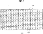
- FIG. 2 is a diagram for briefly explaining the detection data 100 which the sensor part depicted FIG. 1 outputs.
- the detection data 100 correspond to a value detected by a certain region unit as an upper limit of the change of the electrostatic capacitance is "99", and may be data depicted in FIG. 2 , for example.
- the detection data 100 are formed by sets of detection data 100x respective to detection positions 105.
- the detection data 100x indicating a value "90" in a frame being one of the detection positions 105 and being of a third from left and a fourth from a top. Since the change of the electrostatic capacitance is "90" out of "99” and is a greatest value among all sets of the detection data 100x, it is inferred that the finger would have been closer to the detection position 105. Conversely, because values 4 and 5 are indicated in a lower right and are extremely small values, it is inferred that fingers are not close to this vicinity.
- FIG. 3 is a diagram three-dimensionally illustrating an overview of the detection data 100 depicted in FIG. 1 .
- the detection data 100 are illustrated as is values of multivalued data in plan.
- the multivalued data are depicted with height and shade of color. As illustrated in FIG. 3 , high climaxes occur at an upper left portion, a lower right portion to the upper left portion, and a further upper right portion to the lower right portion.
- the input device 1 of the embodiment can recognize objects having different height and shape of peaks at high accuracy.
- FIG. 4 is a functional block diagram of the input device 1 according to the embodiment of the present invention.
- the input device 1 has been already described with reference to FIG. 1 , and in FIG. 4 , the adjacent region specification part 20 will be further described in detail.
- the adjacent region specification part 20 includes a peak position specification part 40, a label assigning part 50, and a position specification part 60.
- the peak position specification part 40 specifies a maximum peak detection position 110max indicating a maximum value satisfying a certain condition among a plurality of peak detection positions 110 in which values of the detection data 100 in a plurality of detection positions 105 satisfy a certain peak condition. In this case, data of a label described later and the detection data 100 are used.
- the label assigning part 50 conducts a label assigning process for assigning a label, which has been already given to the maximum peak detection position 110max, with respect to the detection positions 105 where the label is not assigned and its detection data 100x are greater than or equal to a first threshold Th_Finger_p, among detection positions 105 surrounding the maximum peak detection position 110max specified by the peak position specification part 40.
- the label to be assigned is a number or a symbol, which specifies each of adjacent regions and is unique for each of the adjacent regions.
- the label is a serial number and is assigned such that a label to be assigned first is 1, a next label is 2, a further following label is 3, and the like. If no duplication is desired, it is not necessary to limit to the serial number, and other numerals and symbols may be used.
- the label assigning part 50 includes an outline tracing part 51 that forms an outline with respect to the detection data 100, and a label determination part 52 that determines the label assigned to the formed outline.
- the outline tracing part 51 specifies detection positions whose values are smaller than or equal to the detection data 100x of the maximum peak detection position 110max, as the outline where the label assigning process is conducted. In this case, label data, the detection data 100, and the maximum peak detection position 110max are used. A process of the outline tracing part 51 will be described with reference to FIG. 9 . A process of the label determination part 52 will be described with reference to FIG. 10 .
- the label determination part 52 conducts the label assigning process for the detection positions 105 in the outline for each of specified outlines.
- the label determination part 52 conducts a process for each of the specified outlines so as to assign a label near to the detection position 105 with respect to the detection position 105 in the outline if there are two or more labels in the outline, and so as to assign a label with respect to the detection position 105 in the outline if there is one label in the outline.
- the adjacent region specification part 20 repeats an update of the maximum peak detection position by the peak position specification part 40 and an update of the label by the label assigning part 50, until there becomes no peak detection position satisfying a condition of the maximum peak detection position 110max.
- the position specification part 60 specifies each of near positions respective to the plurality of objects based on the labels assigned by the label assigning part 50.
- the label is assigned for each of the adjacent regions by the process of the label assigning part 50; however, the position specification part 60 assigns certain position information for this label and each of the adjacent regions, specifies the near position, which indicates a location of the label and the adjacent regions by this position information and is to be coordinates of the label, and updates information of the near position if the information has been possessed.
- the near position for example, a barycentric value of the detection positions in the adjacent region where the label is assigned is used; however, a value itself of the peak detection position 110 in the label may be used.
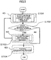
- FIG. 5 is a flowchart for explaining the process of the adjacent region specification part 20 depicted in FIG. 4 .
- the peak position specification part 40 detects the maximum peak detection position 110max based on the detection data 100 input from the sensor part 10 and the label data from the label assigning part 50. At this time, the peak position specification part 40 detects the maximum peak detection position 110max as the detection position 105 where the label is not assigned is a subject.
- the peak position specification part 40 determines whether the maximum peak detection position 110max is detected in step S701, advances to step S703 for a positive determination, and terminates a series of processes for a negative determination.
- a process for detecting the maximum peak detection position in step S701 is conducted again after an outline tracing process and the label assigning process in step S703, and these are repeated until there becomes no maximum peak detection position.
- the label assigning part 50 conducts the outline tracing process and the label assigning process for the maximum peak detection position 110max detected in step S701.
- the position specification part 60 specifies the near positions of the plurality of objects, respectively, based on the label assigned by the label assigning part 50 in step S703.
- FIG. 6 is a diagram for explaining a peak detection process of the peak position specification part 40 depicted in FIG. 4 .
- Each of the peak detection positions 110 depicted in FIG. 6 is a detection position 105 satisfying a peak condition, in which its peak detection data 100x is greater than or equal to a second threshold Th_Exis and the detection data are greater than those at surrounding detection positions among the plurality of detection positions 105.
- the peak position specification part 40 specifies the detection position 105 obtained here as the peak detection position 110.
- the peak position specification part 40 determines the second threshold Th_Exis based on a maximum value of a change value of the detection data 100x. Because the maximum value is "90" in this case, the peak position specification part 40 determines "20" as the second threshold Th_Exis based on the value "90".
- the second threshold Th_Exis will be described as a fixed value in the embodiment; however, because a change value of the electrostatic capacitance tends to decrease as a position of the finger becomes farther from the detection part 11, the second threshold Th_Exis may be also set according to this decreasing tendency so as to decrease as the distance is farther.
- the peak position specification part 40 can be set based on a relationship between the detection data 100x depicted in FIG. 7 and the distance of the object to be inversely proportional or nonlinearly to the distance.
- the peak position specification part 40 obtains the aforementioned peak detection position 110 based on the second threshold Th_Exis determined as described above. Referring to FIG. 8 , this process will be described with reference to FIG. 8 .
- FIG. 8 is a flowchart for explaining a detection process of the maximum peak detection position that the peak position specification part 40 illustrated in FIG. 4 conducts in step S701 depicted in FIG. 5 .
- the peak position specification part 40 selects the detection position 105 of a process subject (step S801). That is, one is selected as the detection position 105.
- an order of selecting the detection position 105 begins from a top left, and the detection position 105 may be sequentially selected one by one to right in the detection data 100x illustrated in FIG. 2 .
- the order may move one below and the detection position 105 may be selected in a further row.
- the detection position 105 may be selected one by one downward.
- the order may shift by one to right, and the detection position 105 may be selected in a further column.
- the order is not limited to begin from the top left. It can be considered to begin from one of various positions such as a top right, a bottom right, a bottom left, a center, and the like.
- the peak position specification part 40 compares and determines whether a value (that is, the change amount of the electrostatic capacitance) indicated by the detection data 100x is greater than the second threshold Th_Exis (step S802). For example, in a case in which ThExist is set as "20”, if the detection data 100 of the detection position 105 indicate "25", the determination becomes Yes, and if the detection data 100 indicate "10", the determination becomes No. When the detection data 100 of the detection position 105 is smaller (Step S802:No), the peak position specification part 40 advances to step S806.
- a value that is, the change amount of the electrostatic capacitance
- the peak position specification part 40 determines whether the label is assigned to the detection position 105, by referring to the label data (object range data) from the label determination part 52 (step S803).
- the label will be described later; however, that the label is attached means that the maximum peak detection position 110max is specified in an area including the detection position 105. Accordingly, when there is the label (step S803:No), the peak position specification part 40 advances to step S806.
- the peak position specification part 40 determines whether the detection data 100x of the detection position 105 is greater than the detection data 100x of eight neighbors at its surrounding (step S804).
- the detection data 100x of the detection positions 105 surrounding the detection position 105 for the detection data 100x indicating "90" are "31", "47”, “39”, “49”, “67”, “48”, “82”, and "63", and "90" is greater than these values.
- the peak position specification part 40 determines that the detection data 100 of the detection position 105, where the detection data 100x indicates "90", is greater than the detection data 100 of the eight neighbors at its surrounding, that is, the peak condition is satisfied (step S804:Yes), and records the detection position 105 as the peak detection position 110 (step S805).
- the peak position specification part 40 After the peak position specification part 40 records the detection position 105 as the peak detection position 110 (step S805), or when the detection data 100 of the detection position 105 is smaller than either set of the detection data 100 of the eight neighbors at its surrounding (step S804:No), the process regarding the detection position 105 ends. Subsequently, the peak position specification part 40 determines whether a peak position detection process is conducted for all detection positions 105 (step S806). Then, in a case of a negative determination (step S806: No), the peak position specification part 40 advances to a next detection position 105 and performs a series of processes in the same manner.
- the peak position specification part 40 detects a maximum detection data 100x among a plurality of extracted peak detection positions 101, as the maximum peak detection position 110max (step S807). For example, when the detection data 100x of the peak detection position 110 as illustrated in FIG. 6 indicate "90", “58", and "31", the peak position specification part 40 detects the detection position 105 where the detection data 100x indicate "90" as the maximum peak detection position 110max.
- the peak position specification part 40 specifies the detection positions 105 where the detection data 100x indicates "90", "58", and "31" as the peak detection position 110. Subsequently, the peak position specification part 40 detects the detection position 105 where the detection data 100x indicates the maximum value "90", as the maximum peak detection position 110max.
- the label assigning part 50 includes the outline tracing part 51 and the label determination part 52.
- the label assigning part 50 conducts the label assigning process of step S703 illustrated in FIG. 5 .
- the label assigning part 50 conducts the label assigning process with respect to the detection position 105 based on the maximum peak detection position 110max described in step S701 of FIG. 5 and with reference to FIG. 8 .
- FIG. 9 is a flowchart for explaining the outline tracing process conducted by the outline tracing part 51 illustrated in FIG. 4 .
- the outline tracing process starts.
- the outline tracing part 51 determines where the maximum peak detection position 110max is input from the peak position specification part 40, advances to step S902 in a case of a positive determination, and repeats this determination in a case of a negative determination.
- the outline tracing part 51 advances to step S902 in the case of the positive determination.
- the outline tracing part 51 assigns a new label to the maximum peak detection position 110max.
- the outline tracing part 51 conducts the label assigning process depicted below with respect to the detection positions 105 of the surroundings based on the maximum peak detection position 110max.
- step S701 illustrated in FIG. 5 is assigned.
- the outline tracing part 51 calculates the first threshold Th_Finger_p based on the detection data 100x of the maximum peak detection position 110max input in step S901 (step S902).
- a detection position 105 having a value greater than the first threshold Th_Finger_p as the detection data 100 is regarded as being in the range of the object, and a detection position 105 having a value smaller than or equal to the first threshold Th_Finger_p is regarded as being outside the range of the object, so that an outline of the range of the object is specified.
- the first threshold Th_Finger_p is derived by a calculation formula so as to be a value smaller than the detection data 100 of the maximum peak detection position 110max. Moreover, the first threshold Th_Finger_p is set to be a threshold such that a noise due to a peak is absorbed; however, a peak due to a finger is not absorbed.
- the first threshold Th_Finger_p may be a value prepared beforehand; however, the first threshold Th_Finger_p may be calculated based on any formula, or may be calculated by multiplying the detection data 100x of the maximum peak detection position 110max by a constant coefficient. For example, in an example illustrated in FIG. 6 , regarding the maximum peak detection position 110max where the detection data 100x is "90", for example, the first threshold Th_Finger_p is set to be "41".
- the outline tracing part 51 conducts an outline trace by using the first threshold Th_Finger_p calculated in step S902 (step S903). That is, the outline tracing part 51 forms an outline, in which the detection position 105 where the detection data 100x is greater than the first threshold Th_Finger_p is in the range of the object.
- the outline to be formed is not limited to one, and in this case, the detection part 11 traces a plurality of outlines from one first threshold Th_Finger_p.
- the label assigning process by the label determination part 52 illustrated in FIG. 10 is conducted.
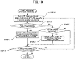
- FIG. 10 is a flowchart for explaining the label assigning process of step S703 illustrated in FIG. 5 , which is conducted by the label determination part 52 depicted in FIG. 4 .
- FIG. 10 The process illustrated in FIG. 10 is conducted following the outline tracing process depicted in FIG. 9 .
- the label determination part 52 selects one from the plurality of outlines, and checks whether the label is assigned to the detection positions 105 inside the one outline (step S910). In a case of one outline, that outline becomes a selection subject.
- the label determination part 52 determines whether there are two or more labels in a selected outline (step S911), and advances to step S913 when two or more labels are included or to step S912 when zero or one label is included. For example, when step S703 is conducted first, because only a first label assigned in step S902 described above, a number of labels in the selected outline indicates 0 or 1, and thus, the label determination part 52 advances to step S912.
- step S703 returning to step S701 after an end of the label assigning process in step S703, a new maximum peak detection position 110max is detected by the peak position specification part 40, and a new label assigning process is conducted with respect to the new maximum peak detection position 110max. That is, a label is added. Therefore, the number of labels is not limited to 0 or 1, and may be two or more. In this case, a positive determination is resulted in step S911, and a process of step S914 is conducted.
- step S911: No when it is determined that two or more labels are not included (step S911: No), the label determination part 52 determines whether the number of labels being included indicates 1 (step S912). When it is determined that none of the labels is included (step S912: No), that is, it is considered that the maximum peak detection position 110max is not included inside the outline, a new labeling process is not conducted for an inside of this outline, and the label determination part 52 advances to step S915.
- step S912 When it is determined that one label is included (step S912: Yes), the label determination part 52 fills all detection positions 105 in a range corresponding to the inside of the outline (step S913), and advances to step S915.
- step S911 when it is determined that two or more labels are included in step S911 (step S911: Yes), because one label alone is applied to the detection position 105, it is necessary to determine to which label the detection positions 105 inside the outline belongs. Accordingly, the label determination part 52 assigns a label having closest label coordinates among a plurality of labels to the detection positions 105 in the range corresponding to the inside of the outline (step S914), and advances to step S915.
- the label determination part 52 calculates distances to a label A and a label B in the outline and assigns a nearest label to the detection position 105 of the process subject. For example, in a case in which coordinates of the label A are (3, 3) and coordinates of the label B are (4, 4), because the label A is closer, the label A is assigned. However, in a case in which coordinates of the detection position 105 of the process subject are (5, 6), because the label B is closer, the label A is assigned. This is performed for all detection positions 105 in the outline.
- the label determination part 52 determines whether the label assigning process is conducted for all outlines formed by the outline tracing process described by referring to FIG. 9 (step S915).
- step S915 In a case of a negative determination (step S915: No), the label determination part 52 returns to step S910, and preforms the label assigning process for a next outline. However, in a case of a positive determination (step S915: Yes), the label determination part 52 terminates the label assigning process for the maximum peak detection position 110max of a current process subject.
- the peak position specification part 40 begins a maximum peak detection position detection process of step S701 illustrated in FIG. 5 , and conducts a process for detecting the maximum peak detection position 110max among detection positions 105 to which the label is not assigned.
- step S704 a position specification process by the position specification part 60 is conducted (step S704).
- the position specification part 60 conducts the position specification process (step S704 illustrated in FIG. 5 ) for specifying respective near positions respective to a plurality of objects approaching to the detection part 11, based on coordinates (position information) of the detection positions 105 to which the label determination part 52 assigns the labels.
- the position specification part 60 specifies a barycentric position to which the label is assigned as the near position of the object corresponding to the label for each of labels assigned to the detection positions 105 by the label determination part 52.
- a near position specification method of the object by the position specification part 60 there is no particular limitation as long as a method using the label and the detection positions 105 to which the labels are assigned.
- a process of the adjacent region specification part 20 illustrated in FIG. 4 will be described by using the detection data 100 illustrated in FIG. 2 and FIG. 6 as an example.
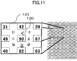
- FIG. 11 is a diagram for explaining a case of conducting the process of step S701 illustrated in FIG. 5 and FIG. 8 by using examples illustrated in FIG. 2 and FIG. 6 .
- the detection position 105 (hereinafter, referred to as a detection position 120) where the detection data 100 indicate "90" is detected as the maximum peak detection position 110max.
- the peak position specification part 40 also specifies detection data 100x indicating a maximum value among the peak detection positions 110 to be subjects.
- the peak detection positions 110 are the detection positions 105, of which their detection data 100x are greater than the second threshold Th_Exis (in this example, assumed as "20"), and to which the label is not assigned, and each of them has the detection data 100x greater than the detection positions 105 of eight neighbors at its surrounding.
- Th_Exis in this example, assumed as "20”
- step S701 the value "90" of the detection data 100 at the detection position 120 illustrated in FIG. 11 is greater than the second threshold Th_Exis being "20". Moreover, the label is not assigned to the detection position 120. Also, as illustrated in FIG. 11 , "90" of the detection data 100x of the detection position 120 indicates a value greater than the detection data 100 of eight neighbors at its surrounding. Therefore, the detection position 120 satisfies a peak requirement as the peak detection position 110. Moreover, since the detection data 100 of the detection position 120 indicates the maximum value, the detection position 120 is detected as the maximum peak detection position 110max.
- the peak position specification part 40 allows the same value for four neighbors: right, bottom left, bottom, and bottom right, while conducting a comparison in order to exclude the same value for four neighbors: upper left, top, upper right, and left, during the comparison with the 8 neighbors. This is a measure for when the same values are arranged. If a comparison, which does not allow the same value for all 8 neighbors, a definition of a peak pixel is not satisfied in a case in which the same values are arranged.
- FIG. 12A, FIG. 12B, and FIG. 12C are diagrams for explaining a case of conducting the process of step S703 illustrated in FIG. 5 , FIG. 9 , and FIG. 10 at the first time by using examples depicted in FIG. 2 and FIG. 6 in a first embodiment of the present invention.
- the outline tracing part 51 conducts the outline tracing process based on the detection data 100 of the detection position 120.
- the outline tracing part 51 calculates the first threshold Th_Finger_p, and forms an outline 122 and an outline 123 by the outline trace based on the first threshold Th_Finger_p.
- the first threshold Th_Finger_p indicates "41".
- the outline tracing part 51 forms the outline as the detection position 105 greater than the first threshold Th_Finger_p is in the range of the object among the detection positions 105 surrounding the detection position 120.
- the label determination part 52 conduct a process filling an inside of the outline formed by the outline tracing part 51 with the labels. As illustrated in FIG. 12C , because the label "1" alone exists inside the outline 122 at the upper left, the label determination part 52 assigns the label "1" to all detection positions 105 inside the outline 122 at the upper left. Since the outline 123 does not include the label inside, the label determination part 52 does not assign the label this time.
- Object range data 124 to which the label "1" has been assigned because a first process illustrated in FIG. 12A, FIG. 12B, and FIG. 12C , are acquired.
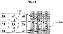
- FIG. 13 is a diagram for explaining a case of conducting the process of step S702 illustrated in FIG. 5 and FIG. 8 at a second time in the first embodiment of the present invention.
- step S703 illustrated in FIG. 5 described by using FIG. 12A, FIG. 12B, and FIG. 12C .
- the label of "1" has been already assigned to the detection position 120, which is a previous maximum peak detection position 110max, such that the detection position 120 is not selected as the maximum peak detection position 110max.
- a detection position 130 which is a detection position 105 having the detection data 100x of "58" being a second greatest value, is detected as the maximum peak detection position 110max.
- "58" is greater than a value "20" of the second threshold Th_Exist, the label is not assigned to the detection position 130, and "58" is greater than the detection data 100 of the detection position 105 of the eight neighbors at the surrounding as illustrated in surrounding data 131.
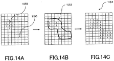
- FIG. 14 is a diagram for explaining a case of conducting the process of step S703 illustrated in FIG. 5 , FIG. 9 , and FIG. 10 at a second time by using the examples of FIG. 2 and FIG. 6 in the first embodiment of the present invention.
- a label "2" is assigned to the detection position 130 by the outline tracing part 51, as illustrated in FIG. 14A .
- the outline tracing part 51 conducts the outline processing process based on the detection data 100x of the detection position 130.
- the outline tracing part 51 calculates the first threshold Th_Finger_p, and forms the outline 133 by the outline trace based on this threshold.
- the first threshold Th_Finger_p indicates "31".
- the outline tracing part 51 forms the outline 133 as a detection position 105 greater than the first threshold Th_Finger_p is in the range of the object among the detection positions 105 surrounding the detection position 120.
- the label determination part 52 conducts the process for filling the inside of the outline formed by the outline tracing part 51. As illustrated in FIG. 14B , the label "1" and the label "2" exist inside the outline 133.
- the label determination part 52 calculates a distance d_1 toward the label "1” and a distance d_2 toward the label "2" from respective coordinates of the detection positions 105 in the outline 133. Then, the label determination part 52 assigns a label having a shorter distance between the distance d_1 and the distanced_2.
- step S703 illustrated in FIG. 5 described by referring to FIG. 14
- step S701 depicted in FIG. 13 at a third time will be conducted.
- a detection position 140 which is a detection position 105 having the detection data of a third greatest "31", is detected as the maximum peak detection position 110max.
- FIG. 15 is a diagram for explaining a case of conducting the process of step S703 illustrated in FIG. 5 , FIG. 9 , and FIG. 10 at a third time by using the examples of FIG. 2 and FIG. 6 in the first embodiment of the present invention.
- the detection position 140 when the detection position 140 is detected as the maximum peak detection position 110max, by the outline tracing part 51, as illustrated in FIG. 15A , the label "3" is assigned to the detection position 140.
- the outline tracing part 51 conducts the outline tracing process based on the detection data 100 of the detection position 130.
- the outline tracing part 51 calculates "19" as the first threshold Th_Finger_p, and forms an outline 141 by the outline trace based on this threshold.
- the label determination part 52 conducts the process for filling the label inside the outline formed by the outline tracing part 51. As illustrated FIG. 15B , the label "1", the label "2", and the label "3" exist inside the outline 141.
- the label determination part 52 calculates the distance d_1 toward the coordinates of the label "1", the distance d_2 toward the coordinates of the label "2", and the distance d_3 toward the coordinates of the label "3", from the respective coordinates of the detection positions 105 inside the outline 141. Next, the label determination part 52 assigns a label having a shorter distance among the distance d_1, the distance d_2, and the distance d_3, to each of the detection positions 105.
- FIG. 16 is a diagram for explaining a case of conducting the process of step S703 illustrated in FIG. 5 , FIG. 9 , and FIG. 10 at a fourth time (last time) by using the examples of FIG. 2 and FIG. 6 in the first embodiment of the present invention.
- a detection position 105 having a fourth greatest value "25" since the label "3" has been already assigned by the label assigning process described by referring to FIG. 15 , this detection position 105 does not become a candidate of the maximum peak detection position 110max.
- a detection position 105 having a fifth greatest value "12" includes detection data 100 greater than eight neighbors at its surrounding; however, because this value is smaller than "20" of the second threshold Th_Exist, this position does not become the peak detection position 110.
- the second threshold Th_Exist is provided in a condition of the peak detection position 110 to prevent recognition of peaks as fingers due to noise.
- An appropriate value is selected as the second threshold Th_Exist based on noise tolerance of a sensor.
- the adjacent region specification part 20 acquires the negative determination (No) in step S702 illustrated in FIG. ?1, a position specifying process (S704) by the position specification part 60 depicted in FIG. 5 is finally conducted based on object range data 412 illustrated in FIG. 15A and FIG. 15B .
- the input device of the present embodiment because a plurality of peak detection positions are detected, and the label is assigned for each of the peak detection positions concerning the detection positions at its surrounding, an object can be discriminated as the peak detection position is set to be a center. Since each of adjacent regions having the peak detection position can be labeled, it is possible to specify an appropriate adjacent regions excluding a detection position which may be noise; accordingly, it is possible to improve accuracy of separating and recognizing an object. In particular, it is possible to provide the input device capable of conducting recognitions of a plurality of objects having different shapes and distances.
- the adjacent region is specified and separated for each of the specified outlines.
- the label assigning process is conducted for each of the outlines, it is possible to label each of outlines having the peak detection positions inside and to specify the range of the object while excluding a region to be noise to which the label is not assigned.
- a basic configuration and process flow is the same as the first embodiment.
- the first embodiment a case of repeating the detection process of the maximum peak detection position 110max every time the outline tracing process and the label assigning process is illustrated; however, in the second embodiment, before the outline tracing process and the label assigning process, all peak detection positions 110, to which a process is conducted sequentially as the maximum peak detection position 110max are detected. Thereby, it is possible to reduce a process time.
- a functional block of the input device of the second embodiment is the same as that of the first embodiment illustrated in FIG. 4 .
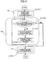
- FIG. 17 is a flowchart for explaining a process of the adjacent region specification part illustrated in FIG. 4 of the second embodiment of the present invention.
- the peak position specification part 40 detects a detection position 105, of which the detection data 100x is greater than or equal to the second threshold Th_Exis and is greater than surrounding detection positions 105, as the peak detection position 110 based on the detection data 100 input from the sensor part 10, stores the detection position 105 in array Peaks.
- the peak position specification part 40 stores the peak detection position 110 to the array Peaks to arrange the detection data 100x in a descending order. Thereby, the detection data 100x of a beginning of the array Peaks indicate the greatest peak detection position 110.
- the detection data 100x are stored in the array Peaks in an order of peak detection positions 110 of "90", "58", "31", and "25".
- the outline tracing part 51 determines whether there is a peak detection position 110, to which step S703 is not conducted, in the array Peaks, advances to step S1703 in a case of a position determination (yes), and advances to step S1704 in a case of a negative determination (no).
- the outline tracing part 51 retrieves the peak detection position 110 not being conducted from the beginning of the array Peaks as the maximum peak detection position 110max.
- the outline tracing part 51 conducts the outline tracing process and the label assigning process regarding the maximum peak detection position 110max retrieved in step S1703.
- the outline tracing process and the label assign process of the present embodiment conduct processes basically similar to processes of steps S902 and S093 illustrated in FIG. 9 and a process illustrated in FIG. 10 , which describe the maximum peak detection position 110max retrieved from the array Peaks.
- the outline tracing part 51 moves the peak detection process 110 retrieved from the beginning of the array Peaks to a fixed peak array Fixed_Peak. Subsequently, the outline trace is conducted similar to the first embodiment, regarding the peak detection position 110 retrieved as the maximum peak detection position 110max from the beginning of the array Peaks.
- the outline tracing part 51 assigns the label of the peak detection position 110 with respect to the detection positions 105 inside the outline.
- the outline tracing part 51 assigns the label of the peak detection position 110 having a closest distance with respect to the detection positions 105 inside the outline, similar to the first embodiment.
- the outline tracing part 51 moves the peak detection positions 110 in the array Peaks to a set Clear_Peaks of peak detection positions 110 not considered as the label of the of the peak detection positions 110 of the array Peaks.
- the position specification part 60 specifies respective near positions of a plurality of objects based on the labels assigned by the label assigning part 50 in step S1703, in the same manner as the first embodiment.
- FIG. 5 and FIG. 17 a case of conducting the position specifying process by the position specification part 60 after conducting the label assigning process for all detection positions 105 is illustrated. Alternatively, every time the label assigning process is conducted with respect to the maximum peak detection position 110max, the position specifying process by the position specification part 60 may be conducted.
- the present invention may be applied to an object detection device for detecting adjacent regions or near positions of a plurality of objects.
- the invention is described on a basis of a user interface device, which inputs information by an operation of a finger or the like; however, the input device of the present invention is applicable widely for devices for inputting information depending on a change of the electrostatic capacitance of a detection electrode caused by proximity of any one of various objects, which are not limited to a human body.
Landscapes
- Engineering & Computer Science (AREA)
- General Engineering & Computer Science (AREA)
- Theoretical Computer Science (AREA)
- Human Computer Interaction (AREA)
- Physics & Mathematics (AREA)
- General Physics & Mathematics (AREA)
- Image Analysis (AREA)
- Position Input By Displaying (AREA)
- User Interface Of Digital Computer (AREA)
Claims (9)
- Dispositif d'entrée qui comprend :un élément (10) faisant office de capteur qui est configuré pour détecter des états d'approche d'un certain nombre d'objets à un certain nombre de positions de détection ; etun élément de spécification de zones adjacentes (20) qui est configuré pour spécifier des zones adjacentes desdits plusieurs objets en se basant sur des données de détection émises à partir de l'élément (10) faisant office de capteur ;dans lequel l'élément de spécification de zones adjacentes (20) comprend :un élément (40) qui représente un pic de spécification d'une position qui est configuré pour spécifier une position qui correspond à un pic de détection dont une valeur des données de détection satisfait à une certaine condition correspondant à un pic parmi lesdites plusieurs positions de détection ;caractérisé en ce que l'élément de spécification de zones adjacentes (20) comprend en outre :un élément d'attribution d'un marqueur (50) qui est configuré pour mettre en oeuvre un processus d'attribution de marqueur qui attribue un marqueur appliqué à la position qui correspond à un pic de détection à une ou plusieurs positions de détection auxquelles le marqueur n'a pas été attribué et qui présentent des données de détection qui sont supérieures ou égales à un premier seuil que l'on définit en se basant sur les données de détection de la position qui correspond à un pic de détection, parmi des positions de détection environnantes par rapport à la position qui correspond à un pic de détection ;dans lequel l'élément qui attribue un marqueur (50) spécifie, à titre de cadre, des positions de détection dont la valeur des données de détection est supérieure ou égale au premier seuil qui est inférieur à la valeur des données de détection de la position qui correspond à un pic de détection faisant l'objet de la mise en œuvre du processus d'attribution de marqueur, et met en œuvre le processus d'attribution de marqueur pour les positions de détection qui sont reprises à l'intérieur du cadre ;dans lequel l'élément qui attribue un marqueur (50) attribue le marqueur qui présentent les coordonnées de marqueur les plus proches parmi un certain nombre de marqueurs aux positions de détection dans la plage qui correspond à l'intérieur du cadre, lorsque deux marqueurs ou plus se retrouvent à l'intérieur du cadre, pour chacun des cadres en train d'être spécifiés, et met en œuvre un processus destiné à l'attribution du marqueur par rapport aux positions de détection qui se retrouvent à l'intérieur du cadre, dans le cas où un seul marqueur est présent à l'intérieur du cadre.
- Dispositif d'entrée tel que revendiqué à la revendication 1, dans lequel :l'élément (40) qui représente un pic de spécification d'une position spécifie une position qui correspond à un pic de détection maximal, auquel la valeur des données de détection d'une position de détection satisfait à une certaine condition correspondant à un pic pour lesdites une ou plusieurs positions auxquelles le marqueur n'a pas été attribué parmi lesdites plusieurs positions de détection, avant d'entamer le processus d'attribution de marqueur par l'intermédiaire de l'élément (50) qui attribue un marqueur ;l'élément (50) qui attribue un marqueur met en œuvre le processus d'attribution de marqueur pour la position qui correspond à un pic de détection maximal qui a été spécifiée juste avant par l'élément (40) qui représente un pic de spécification d'une position ; etl'élément (40) qui représente un pic de spécification d'une position spécifie la position qui correspond à un pic de détection maximal après le processus d'attribution de marqueur par l'intermédiaire de l'élément (50) qui attribue un marqueur.
- Dispositif d'entrée tel que revendiqué à la revendication 1, dans lequel :l'élément (40) qui représente un pic de spécification d'une position spécifie un certain nombre de positions qui correspondent à un pic de détection, auxquelles des valeurs des données de détection satisfont à une certaine condition correspondant à un pic avant d'entamer le processus d'attribution d'un marqueur par l'intermédiaire de l'élément qui attribue un marqueur ; etl'élément (50) qui attribue un marqueur spécifie, d'une manière séquentielle, une position qui correspond à un pic de détection maximal, à partir de la position qui correspond à un pic de détection qui présente une valeur des données de détection qui est supérieure parmi lesdits plusieurs positions qui correspondent à un pic de détection qui sont en train d'être spécifiées, et met en œuvre le processus d'attribution de marqueur pour la position qui correspond à un pic de détection maximal.
- Dispositif d'entrée tel que revendiqué dans l'une quelconque des revendications 1 à 3, dans lequel l'élément (40) qui représente un pic de spécification d'une position spécifie, à titre de position qui correspond à un pic de détection parmi lesdites plusieurs positions de détection, une position de détection à laquelle les données de détection sont supérieures à un deuxième seuil et sont supérieures à celles des positions de détection qui entourent la position de détection en question.
- Dispositif d'entrée tel que revendiqué à la revendication 4, dans lequel l'élément (40) qui représente un pic de spécification d'une position détermine le deuxième seuil en se basant sur une valeur maximale d'une valeur de changement des données de détection.
- Dispositif d'entrée tel que revendiqué dans l'une quelconque des revendications 1 à 5, qui comprend en outre :
un élément de spécification d'une position (60) qui est configuré pour spécifier des positions proches desdits plusieurs objets, respectivement, en se basant sur le marqueur. - Dispositif d'entrée tel que revendiqué à la revendication 6, dans lequel l'élément de spécification d'une position (60) obtient les positions proches en calculant une valeur de centre de masse des positions de détection dans la zone adjacente dans laquelle un même marqueur a été attribué.
- Dispositif d'entrée tel que revendiqué à la revendication 2 ou 3, dans lequel l'élément (50) qui attribue un marqueur met en œuvre le processus d'attribution d'un marqueur pour toutes les positions qui correspondent à un pic de détection maximal.
- Procédé de détection d'un objet qui comprend :une étape destinée à un pic de spécification qui a pour objet de spécifier une position correspondant à un pic de détection, dont une valeur des données de détection satisfait à une certaine condition correspondant à un pic parmi un certain nombre de positions de détection, en se basant sur les données de détection qui indiquent des états d'approche d'un certain nombre d'objets auxdites plusieurs positions de détection ;caractérisé parune étape destiné à l'attribution d'un marqueur qui a pour objet la mise en oeuvre d'un processus d'attribution d'un marqueur qui attribue un marqueur appliqué à la position correspondant à un pic de détection, à une ou plusieurs positions de détection auxquelles le marqueur n'a pas été attribué et qui présentent des données de détection qui sont supérieures ou égales à un premier seuil que l'on définit en se basant sur les données de détection de la position qui correspond à un pic de détection, parmi des positions de détection environnantes par rapport à la position qui correspond à un pic de détection ;dans lequel des positions de détection sont spécifiées sous la forme d'un cadre dont la valeur des données de détection est supérieure ou égale au premier seuil qui est inférieur à la valeur des données de détection de la position qui correspond à un pic de détection, visée par la mise en œuvre du processus d'attribution d'un marqueur, et le processus d'attribution d'un marqueur pour les positions de détection est mis en œuvre à l'intérieur du cadre ;le marqueur présentant des coordonnées de marqueur les plus proches parmi un certain nombre de marqueurs, est attribué aux positions de détection dans la plage qui correspond à l'intérieur du cadre, lorsque deux marqueurs ou plus sont présents à l'intérieur du cadre, pour chacun des cadres en train d'être spécifiés, et un processus destiné à l'attribution du marqueur est mis en œuvre par rapport aux positions de détection à l'intérieur du cadre dans le cas où un seul marqueur est présent à l'intérieur du cadre.
Applications Claiming Priority (2)
| Application Number | Priority Date | Filing Date | Title |
|---|---|---|---|
| JP2015122879 | 2015-06-18 | ||
| PCT/JP2016/067260 WO2016204069A1 (fr) | 2015-06-18 | 2016-06-09 | Dispositif d'entrée, et dispositif et procédé de détection d'objet |
Publications (3)
| Publication Number | Publication Date |
|---|---|
| EP3312704A1 EP3312704A1 (fr) | 2018-04-25 |
| EP3312704A4 EP3312704A4 (fr) | 2018-05-02 |
| EP3312704B1 true EP3312704B1 (fr) | 2022-05-11 |
Family
ID=57545614
Family Applications (1)
| Application Number | Title | Priority Date | Filing Date |
|---|---|---|---|
| EP16811544.2A Active EP3312704B1 (fr) | 2015-06-18 | 2016-06-09 | Dispositif d'entrée, et dispositif et procédé de détection d'objet |
Country Status (6)
| Country | Link |
|---|---|
| US (1) | US10712881B2 (fr) |
| EP (1) | EP3312704B1 (fr) |
| JP (1) | JP6402251B2 (fr) |
| KR (1) | KR102024180B1 (fr) |
| CN (1) | CN107683452B (fr) |
| WO (1) | WO2016204069A1 (fr) |
Families Citing this family (3)
| Publication number | Priority date | Publication date | Assignee | Title |
|---|---|---|---|---|
| CN109537175B (zh) * | 2018-12-28 | 2020-09-04 | 杰克缝纫机股份有限公司 | 一种商标切割系统以及方法 |
| JP7556501B2 (ja) * | 2020-12-25 | 2024-09-26 | アルプスアルパイン株式会社 | 静電座標入力装置および静電座標算出方法 |
| CN115480662A (zh) | 2021-05-28 | 2022-12-16 | 华为技术有限公司 | 悬浮操控时的感应区域分离方法、装置、悬浮操控遥控器 |
Family Cites Families (15)
| Publication number | Priority date | Publication date | Assignee | Title |
|---|---|---|---|---|
| JP4766340B2 (ja) | 2006-10-13 | 2011-09-07 | ソニー株式会社 | 近接検知型情報表示装置およびこれを使用した情報表示方法 |
| US8284165B2 (en) | 2006-10-13 | 2012-10-09 | Sony Corporation | Information display apparatus with proximity detection performance and information display method using the same |
| KR101526626B1 (ko) | 2007-07-12 | 2015-06-05 | 아트멜 코포레이션 | 2차원 터치 패널 |
| TWI398807B (zh) * | 2009-04-07 | 2013-06-11 | Ite Tech Inc | 觸控裝置之定位裝置及其定位方法 |
| US8154529B2 (en) * | 2009-05-14 | 2012-04-10 | Atmel Corporation | Two-dimensional touch sensors |
| JP5451181B2 (ja) * | 2009-05-25 | 2014-03-26 | 株式会社ジャパンディスプレイ | 物体の接触または近接を検出するセンサ装置 |
| KR20140008292A (ko) | 2010-09-15 | 2014-01-21 | 어드밴스드 실리콘 에스아 | 멀티터치 디바이스로부터 임의의 터치 회수를 감지하는 방법 |
| JP5606242B2 (ja) * | 2010-09-24 | 2014-10-15 | 株式会社ジャパンディスプレイ | 表示装置 |
| KR101395991B1 (ko) * | 2011-09-01 | 2014-05-19 | 엘지디스플레이 주식회사 | 터치센서를 가지는 표시장치와 그의 터치성능 향상방법 |
| KR101885216B1 (ko) * | 2011-12-30 | 2018-08-30 | 삼성전자주식회사 | 터치 센서 시스템의 멀티 터치 구분 방법 |
| KR102092664B1 (ko) * | 2013-02-21 | 2020-03-24 | 주식회사 실리콘웍스 | 차동 터치 센싱 시스템의 좌표 선택 회로 및 방법 |
| US9158411B2 (en) * | 2013-07-12 | 2015-10-13 | Tactual Labs Co. | Fast multi-touch post processing |
| US20160070413A1 (en) * | 2013-04-08 | 2016-03-10 | 3M Innovative Properties Company | Method and System for Resolving Multiple Proximate Touches |
| JP2015032235A (ja) * | 2013-08-06 | 2015-02-16 | ソニー株式会社 | タッチ検出回路、タッチ検出方法、および電子機器 |
| JP6412310B2 (ja) * | 2013-12-26 | 2018-10-24 | エルジー ディスプレイ カンパニー リミテッド | タッチ検出装置およびタッチ検出方法 |
-
2016
- 2016-06-09 EP EP16811544.2A patent/EP3312704B1/fr active Active
- 2016-06-09 WO PCT/JP2016/067260 patent/WO2016204069A1/fr not_active Ceased
- 2016-06-09 KR KR1020177036167A patent/KR102024180B1/ko active Active
- 2016-06-09 JP JP2017525193A patent/JP6402251B2/ja active Active
- 2016-06-09 CN CN201680034712.2A patent/CN107683452B/zh active Active
-
2017
- 2017-12-13 US US15/840,291 patent/US10712881B2/en active Active
Also Published As
| Publication number | Publication date |
|---|---|
| KR20180008680A (ko) | 2018-01-24 |
| KR102024180B1 (ko) | 2019-09-23 |
| US10712881B2 (en) | 2020-07-14 |
| JPWO2016204069A1 (ja) | 2018-04-19 |
| JP6402251B2 (ja) | 2018-10-10 |
| WO2016204069A1 (fr) | 2016-12-22 |
| US20180101265A1 (en) | 2018-04-12 |
| EP3312704A1 (fr) | 2018-04-25 |
| CN107683452B (zh) | 2021-01-12 |
| EP3312704A4 (fr) | 2018-05-02 |
| CN107683452A (zh) | 2018-02-09 |
Similar Documents
| Publication | Publication Date | Title |
|---|---|---|
| CN108288088B (zh) | 一种基于端到端全卷积神经网络的场景文本检测方法 | |
| KR101159955B1 (ko) | 물체의 접촉 또는 근접을 검출하는 센서 장치, 및 그것을 탑재한 표시 장치 | |
| KR20170030613A (ko) | 터치 분류 | |
| TWI550503B (zh) | Operating device | |
| JP2020106966A (ja) | 物体認識装置および物体認識方法 | |
| CN106650648A (zh) | 擦除笔迹的识别方法和系统 | |
| EP3312704B1 (fr) | Dispositif d'entrée, et dispositif et procédé de détection d'objet | |
| JPWO2018088144A1 (ja) | 静電容量センサ | |
| US9846519B2 (en) | Input device, and method and program for controlling the same | |
| KR101281461B1 (ko) | 영상분석을 이용한 멀티 터치 입력 방법 및 시스템 | |
| Lee et al. | Classification network-guided weighted k-means clustering for multitouch detection | |
| JP6705052B2 (ja) | 入力装置とその制御方法及びプログラム | |
| CN111095163A (zh) | 用于依据姿态来检测用户输入的方法和设备 | |
| US9733775B2 (en) | Information processing device, method of identifying operation of fingertip, and program | |
| US9785293B2 (en) | Input device, and information input method of the same | |
| CN112596603A (zh) | 核电站控制系统的手势操控方法、装置、设备及存储介质 | |
| US20180189541A1 (en) | Optical identification method and optical identification system | |
| US10234990B2 (en) | Mapping of position measurements to objects using a movement model | |
| CN110134269B (zh) | 通过环状触摸岛验证多指触摸检测的电子设备及相关方法 | |
| KR20230031138A (ko) | 비접촉 입력 장치 | |
| KR101601660B1 (ko) | 깊이 영상을 이용한 손 영역 분류 방법 및 그 장치 | |
| US20170024051A1 (en) | Multitouch frame matching with distance fields | |
| JP5630098B2 (ja) | 情報処理装置およびプログラム | |
| JPH05225396A (ja) | 手書き文字認識装置 | |
| JP2017027524A (ja) | 手書き情報入力装置手書き情報入力方法プログラム |
Legal Events
| Date | Code | Title | Description |
|---|---|---|---|
| STAA | Information on the status of an ep patent application or granted ep patent |
Free format text: STATUS: THE INTERNATIONAL PUBLICATION HAS BEEN MADE |
|
| PUAI | Public reference made under article 153(3) epc to a published international application that has entered the european phase |
Free format text: ORIGINAL CODE: 0009012 |
|
| STAA | Information on the status of an ep patent application or granted ep patent |
Free format text: STATUS: REQUEST FOR EXAMINATION WAS MADE |
|
| 17P | Request for examination filed |
Effective date: 20171214 |
|
| AK | Designated contracting states |
Kind code of ref document: A1 Designated state(s): AL AT BE BG CH CY CZ DE DK EE ES FI FR GB GR HR HU IE IS IT LI LT LU LV MC MK MT NL NO PL PT RO RS SE SI SK SM TR |
|
| AX | Request for extension of the european patent |
Extension state: BA ME |
|
| A4 | Supplementary search report drawn up and despatched |
Effective date: 20180329 |
|
| RIC1 | Information provided on ipc code assigned before grant |
Ipc: G06F 3/044 20060101ALI20180323BHEP Ipc: G06F 3/041 20060101AFI20180323BHEP |
|
| DAV | Request for validation of the european patent (deleted) | ||
| DAX | Request for extension of the european patent (deleted) | ||
| RAP1 | Party data changed (applicant data changed or rights of an application transferred) |
Owner name: ALPS ALPINE CO., LTD. |
|
| STAA | Information on the status of an ep patent application or granted ep patent |
Free format text: STATUS: EXAMINATION IS IN PROGRESS |
|
| 17Q | First examination report despatched |
Effective date: 20200818 |
|
| GRAP | Despatch of communication of intention to grant a patent |
Free format text: ORIGINAL CODE: EPIDOSNIGR1 |
|
| STAA | Information on the status of an ep patent application or granted ep patent |
Free format text: STATUS: GRANT OF PATENT IS INTENDED |
|
| INTG | Intention to grant announced |
Effective date: 20211213 |
|
| GRAS | Grant fee paid |
Free format text: ORIGINAL CODE: EPIDOSNIGR3 |
|
| GRAA | (expected) grant |
Free format text: ORIGINAL CODE: 0009210 |
|
| STAA | Information on the status of an ep patent application or granted ep patent |
Free format text: STATUS: THE PATENT HAS BEEN GRANTED |
|
| AK | Designated contracting states |
Kind code of ref document: B1 Designated state(s): AL AT BE BG CH CY CZ DE DK EE ES FI FR GB GR HR HU IE IS IT LI LT LU LV MC MK MT NL NO PL PT RO RS SE SI SK SM TR |
|
| REG | Reference to a national code |
Ref country code: GB Ref legal event code: FG4D |
|
| REG | Reference to a national code |
Ref country code: CH Ref legal event code: EP |
|
| REG | Reference to a national code |
Ref country code: AT Ref legal event code: REF Ref document number: 1492001 Country of ref document: AT Kind code of ref document: T Effective date: 20220515 |
|
| REG | Reference to a national code |
Ref country code: DE Ref legal event code: R096 Ref document number: 602016072081 Country of ref document: DE |
|
| REG | Reference to a national code |
Ref country code: IE Ref legal event code: FG4D |
|
| REG | Reference to a national code |
Ref country code: LT Ref legal event code: MG9D |
|
| REG | Reference to a national code |
Ref country code: NL Ref legal event code: MP Effective date: 20220511 |
|
| REG | Reference to a national code |
Ref country code: AT Ref legal event code: MK05 Ref document number: 1492001 Country of ref document: AT Kind code of ref document: T Effective date: 20220511 |
|
| PG25 | Lapsed in a contracting state [announced via postgrant information from national office to epo] |
Ref country code: SE Free format text: LAPSE BECAUSE OF FAILURE TO SUBMIT A TRANSLATION OF THE DESCRIPTION OR TO PAY THE FEE WITHIN THE PRESCRIBED TIME-LIMIT Effective date: 20220511 Ref country code: PT Free format text: LAPSE BECAUSE OF FAILURE TO SUBMIT A TRANSLATION OF THE DESCRIPTION OR TO PAY THE FEE WITHIN THE PRESCRIBED TIME-LIMIT Effective date: 20220912 Ref country code: NO Free format text: LAPSE BECAUSE OF FAILURE TO SUBMIT A TRANSLATION OF THE DESCRIPTION OR TO PAY THE FEE WITHIN THE PRESCRIBED TIME-LIMIT Effective date: 20220811 Ref country code: NL Free format text: LAPSE BECAUSE OF FAILURE TO SUBMIT A TRANSLATION OF THE DESCRIPTION OR TO PAY THE FEE WITHIN THE PRESCRIBED TIME-LIMIT Effective date: 20220511 Ref country code: LT Free format text: LAPSE BECAUSE OF FAILURE TO SUBMIT A TRANSLATION OF THE DESCRIPTION OR TO PAY THE FEE WITHIN THE PRESCRIBED TIME-LIMIT Effective date: 20220511 Ref country code: HR Free format text: LAPSE BECAUSE OF FAILURE TO SUBMIT A TRANSLATION OF THE DESCRIPTION OR TO PAY THE FEE WITHIN THE PRESCRIBED TIME-LIMIT Effective date: 20220511 Ref country code: GR Free format text: LAPSE BECAUSE OF FAILURE TO SUBMIT A TRANSLATION OF THE DESCRIPTION OR TO PAY THE FEE WITHIN THE PRESCRIBED TIME-LIMIT Effective date: 20220812 Ref country code: FI Free format text: LAPSE BECAUSE OF FAILURE TO SUBMIT A TRANSLATION OF THE DESCRIPTION OR TO PAY THE FEE WITHIN THE PRESCRIBED TIME-LIMIT Effective date: 20220511 Ref country code: ES Free format text: LAPSE BECAUSE OF FAILURE TO SUBMIT A TRANSLATION OF THE DESCRIPTION OR TO PAY THE FEE WITHIN THE PRESCRIBED TIME-LIMIT Effective date: 20220511 Ref country code: BG Free format text: LAPSE BECAUSE OF FAILURE TO SUBMIT A TRANSLATION OF THE DESCRIPTION OR TO PAY THE FEE WITHIN THE PRESCRIBED TIME-LIMIT Effective date: 20220811 Ref country code: AT Free format text: LAPSE BECAUSE OF FAILURE TO SUBMIT A TRANSLATION OF THE DESCRIPTION OR TO PAY THE FEE WITHIN THE PRESCRIBED TIME-LIMIT Effective date: 20220511 |
|
| PG25 | Lapsed in a contracting state [announced via postgrant information from national office to epo] |
Ref country code: RS Free format text: LAPSE BECAUSE OF FAILURE TO SUBMIT A TRANSLATION OF THE DESCRIPTION OR TO PAY THE FEE WITHIN THE PRESCRIBED TIME-LIMIT Effective date: 20220511 Ref country code: PL Free format text: LAPSE BECAUSE OF FAILURE TO SUBMIT A TRANSLATION OF THE DESCRIPTION OR TO PAY THE FEE WITHIN THE PRESCRIBED TIME-LIMIT Effective date: 20220511 Ref country code: LV Free format text: LAPSE BECAUSE OF FAILURE TO SUBMIT A TRANSLATION OF THE DESCRIPTION OR TO PAY THE FEE WITHIN THE PRESCRIBED TIME-LIMIT Effective date: 20220511 Ref country code: IS Free format text: LAPSE BECAUSE OF FAILURE TO SUBMIT A TRANSLATION OF THE DESCRIPTION OR TO PAY THE FEE WITHIN THE PRESCRIBED TIME-LIMIT Effective date: 20220911 |
|
| PG25 | Lapsed in a contracting state [announced via postgrant information from national office to epo] |
Ref country code: SM Free format text: LAPSE BECAUSE OF FAILURE TO SUBMIT A TRANSLATION OF THE DESCRIPTION OR TO PAY THE FEE WITHIN THE PRESCRIBED TIME-LIMIT Effective date: 20220511 Ref country code: SK Free format text: LAPSE BECAUSE OF FAILURE TO SUBMIT A TRANSLATION OF THE DESCRIPTION OR TO PAY THE FEE WITHIN THE PRESCRIBED TIME-LIMIT Effective date: 20220511 Ref country code: RO Free format text: LAPSE BECAUSE OF FAILURE TO SUBMIT A TRANSLATION OF THE DESCRIPTION OR TO PAY THE FEE WITHIN THE PRESCRIBED TIME-LIMIT Effective date: 20220511 Ref country code: EE Free format text: LAPSE BECAUSE OF FAILURE TO SUBMIT A TRANSLATION OF THE DESCRIPTION OR TO PAY THE FEE WITHIN THE PRESCRIBED TIME-LIMIT Effective date: 20220511 Ref country code: DK Free format text: LAPSE BECAUSE OF FAILURE TO SUBMIT A TRANSLATION OF THE DESCRIPTION OR TO PAY THE FEE WITHIN THE PRESCRIBED TIME-LIMIT Effective date: 20220511 Ref country code: CZ Free format text: LAPSE BECAUSE OF FAILURE TO SUBMIT A TRANSLATION OF THE DESCRIPTION OR TO PAY THE FEE WITHIN THE PRESCRIBED TIME-LIMIT Effective date: 20220511 |
|
| REG | Reference to a national code |
Ref country code: CH Ref legal event code: PL |
|
| REG | Reference to a national code |
Ref country code: DE Ref legal event code: R097 Ref document number: 602016072081 Country of ref document: DE |
|
| REG | Reference to a national code |
Ref country code: BE Ref legal event code: MM Effective date: 20220630 |
|
| PG25 | Lapsed in a contracting state [announced via postgrant information from national office to epo] |
Ref country code: MC Free format text: LAPSE BECAUSE OF FAILURE TO SUBMIT A TRANSLATION OF THE DESCRIPTION OR TO PAY THE FEE WITHIN THE PRESCRIBED TIME-LIMIT Effective date: 20220511 |
|
| PLBE | No opposition filed within time limit |
Free format text: ORIGINAL CODE: 0009261 |
|
| STAA | Information on the status of an ep patent application or granted ep patent |
Free format text: STATUS: NO OPPOSITION FILED WITHIN TIME LIMIT |
|
| PG25 | Lapsed in a contracting state [announced via postgrant information from national office to epo] |
Ref country code: AL Free format text: LAPSE BECAUSE OF FAILURE TO SUBMIT A TRANSLATION OF THE DESCRIPTION OR TO PAY THE FEE WITHIN THE PRESCRIBED TIME-LIMIT Effective date: 20220511 |
|
| 26N | No opposition filed |
Effective date: 20230214 |
|
| PG25 | Lapsed in a contracting state [announced via postgrant information from national office to epo] |
Ref country code: LU Free format text: LAPSE BECAUSE OF NON-PAYMENT OF DUE FEES Effective date: 20220609 Ref country code: LI Free format text: LAPSE BECAUSE OF NON-PAYMENT OF DUE FEES Effective date: 20220630 Ref country code: IE Free format text: LAPSE BECAUSE OF NON-PAYMENT OF DUE FEES Effective date: 20220609 Ref country code: CH Free format text: LAPSE BECAUSE OF NON-PAYMENT OF DUE FEES Effective date: 20220630 |
|
| PG25 | Lapsed in a contracting state [announced via postgrant information from national office to epo] |
Ref country code: SI Free format text: LAPSE BECAUSE OF FAILURE TO SUBMIT A TRANSLATION OF THE DESCRIPTION OR TO PAY THE FEE WITHIN THE PRESCRIBED TIME-LIMIT Effective date: 20220511 Ref country code: BE Free format text: LAPSE BECAUSE OF NON-PAYMENT OF DUE FEES Effective date: 20220630 |
|
| PG25 | Lapsed in a contracting state [announced via postgrant information from national office to epo] |
Ref country code: IT Free format text: LAPSE BECAUSE OF FAILURE TO SUBMIT A TRANSLATION OF THE DESCRIPTION OR TO PAY THE FEE WITHIN THE PRESCRIBED TIME-LIMIT Effective date: 20220511 |
|
| PG25 | Lapsed in a contracting state [announced via postgrant information from national office to epo] |
Ref country code: HU Free format text: LAPSE BECAUSE OF FAILURE TO SUBMIT A TRANSLATION OF THE DESCRIPTION OR TO PAY THE FEE WITHIN THE PRESCRIBED TIME-LIMIT; INVALID AB INITIO Effective date: 20160609 |
|
| PG25 | Lapsed in a contracting state [announced via postgrant information from national office to epo] |
Ref country code: MK Free format text: LAPSE BECAUSE OF FAILURE TO SUBMIT A TRANSLATION OF THE DESCRIPTION OR TO PAY THE FEE WITHIN THE PRESCRIBED TIME-LIMIT Effective date: 20220511 Ref country code: CY Free format text: LAPSE BECAUSE OF FAILURE TO SUBMIT A TRANSLATION OF THE DESCRIPTION OR TO PAY THE FEE WITHIN THE PRESCRIBED TIME-LIMIT Effective date: 20220511 |
|
| PG25 | Lapsed in a contracting state [announced via postgrant information from national office to epo] |
Ref country code: TR Free format text: LAPSE BECAUSE OF FAILURE TO SUBMIT A TRANSLATION OF THE DESCRIPTION OR TO PAY THE FEE WITHIN THE PRESCRIBED TIME-LIMIT Effective date: 20220511 |
|
| PG25 | Lapsed in a contracting state [announced via postgrant information from national office to epo] |
Ref country code: MT Free format text: LAPSE BECAUSE OF FAILURE TO SUBMIT A TRANSLATION OF THE DESCRIPTION OR TO PAY THE FEE WITHIN THE PRESCRIBED TIME-LIMIT Effective date: 20220511 |
|
| PG25 | Lapsed in a contracting state [announced via postgrant information from national office to epo] |
Ref country code: BG Free format text: LAPSE BECAUSE OF FAILURE TO SUBMIT A TRANSLATION OF THE DESCRIPTION OR TO PAY THE FEE WITHIN THE PRESCRIBED TIME-LIMIT Effective date: 20220511 |
|
| PG25 | Lapsed in a contracting state [announced via postgrant information from national office to epo] |
Ref country code: BG Free format text: LAPSE BECAUSE OF FAILURE TO SUBMIT A TRANSLATION OF THE DESCRIPTION OR TO PAY THE FEE WITHIN THE PRESCRIBED TIME-LIMIT Effective date: 20220511 |
|
| PGFP | Annual fee paid to national office [announced via postgrant information from national office to epo] |
Ref country code: DE Payment date: 20250618 Year of fee payment: 10 |
|
| PGFP | Annual fee paid to national office [announced via postgrant information from national office to epo] |
Ref country code: GB Payment date: 20250618 Year of fee payment: 10 |
|
| PGFP | Annual fee paid to national office [announced via postgrant information from national office to epo] |
Ref country code: FR Payment date: 20250625 Year of fee payment: 10 |