EP3312761B1 - Procédé de détection de codes-barres au moyen d'un lecteur de code - Google Patents
Procédé de détection de codes-barres au moyen d'un lecteur de code Download PDFInfo
- Publication number
- EP3312761B1 EP3312761B1 EP16194637.1A EP16194637A EP3312761B1 EP 3312761 B1 EP3312761 B1 EP 3312761B1 EP 16194637 A EP16194637 A EP 16194637A EP 3312761 B1 EP3312761 B1 EP 3312761B1
- Authority
- EP
- European Patent Office
- Prior art keywords
- value
- scan
- received signal
- current
- threshold
- Prior art date
- Legal status (The legal status is an assumption and is not a legal conclusion. Google has not performed a legal analysis and makes no representation as to the accuracy of the status listed.)
- Active
Links
Images


Classifications
-
- G—PHYSICS
- G06—COMPUTING OR CALCULATING; COUNTING
- G06K—GRAPHICAL DATA READING; PRESENTATION OF DATA; RECORD CARRIERS; HANDLING RECORD CARRIERS
- G06K7/00—Methods or arrangements for sensing record carriers, e.g. for reading patterns
- G06K7/10—Methods or arrangements for sensing record carriers, e.g. for reading patterns by electromagnetic radiation, e.g. optical sensing; by corpuscular radiation
- G06K7/10544—Methods or arrangements for sensing record carriers, e.g. for reading patterns by electromagnetic radiation, e.g. optical sensing; by corpuscular radiation by scanning of the records by radiation in the optical part of the electromagnetic spectrum
- G06K7/10821—Methods or arrangements for sensing record carriers, e.g. for reading patterns by electromagnetic radiation, e.g. optical sensing; by corpuscular radiation by scanning of the records by radiation in the optical part of the electromagnetic spectrum further details of bar or optical code scanning devices
- G06K7/10851—Circuits for pulse shaping, amplifying, eliminating noise signals, checking the function of the sensing device
Definitions
- the invention relates to a method for detecting barcodes.
- code readers are typically used which are designed in the form of bar code scanners.
- a code reader has a transmitter emitting light rays and a deflection unit arranged downstream of the transmitter.
- the transmitted light beams are deflected in such a way that they periodically scan a scanning area within one scan.
- the transmitted light beams are reflected from a bar code arranged within the scanning area and are guided to the receiver as received light beams.
- the received light beams and correspondingly the received signals present at the output of the receiver have an amplitude modulation in accordance with the contrast pattern of the bar code.
- the amplitude modulation of the received signals is evaluated in an evaluation unit of the code reader and the bar code is decoded.
- the widths of the individual code elements of this barcode must be determined. This means that the transitions between the light and dark code elements must be determined as precisely as possible on the basis of the received signal.
- the received signal is differentiated in known code readers and then, for each scan, the differentiated temporal received signal curve is evaluated. To determine the light / dark transitions, the differentiated received signal is then evaluated with two threshold values. The maxima of the received signal curve are determined with a positive threshold value, whereby there is a maximum if the local maximum of the differentiated received signal is greater than the positive threshold value. The minima of the received signal curve are determined with a negative threshold value, a minimum being present if the local minimum of the differentiated received signal is smaller than the negative threshold value.
- a problem with this evaluation method is that it presupposes that the barcodes are arranged at a fixed reading distance from the code reader and that the transmitted light beams are focused in such a way that the diameter of the transmitted light beams is smaller than the widths of the code elements of the barcodes in the reading distance.
- the EP 1 087 324 A1 relates to an optoelectronic device for recognizing barcodes, each with an arrangement of light and dark surface elements with at least one transmitter light-emitting transmitter and one receiving-light-receiving receiver with a matrix-like arrangement of receiving elements, the barcode being imaged on the receiver and received signals at the outputs of the receiving elements in the form of gray values corresponding to the structure of the surface elements of the bar code.
- An adaptive threshold value unit is arranged downstream of the receiver, in which the received signals are converted into binary signals and in an evaluation unit downstream of the adaptive threshold value unit, the mark is decoded on the basis of the sequence of the binary signals.
- the US 5,861,616 relates to a device for detecting a waveform of an analog signal.
- the extreme values of the signal are determined and, depending on this, adaptive threshold values that are used before signal evaluation are defined.
- the US 4,468,704 A relates to an adaptive threshold unit for processing image pixels of an image.
- the object of the invention is to provide a method which enables bar codes to be detected by means of a code reader within a large depth of field.
- the invention is therefore based on the basic idea of evaluating the differentiated received signal, which contains the information about a bar code read with the code reader, not with fixed threshold values, but with adaptive threshold values which are dependent on the course of the differentiated received signal. This continuous adjustment of the threshold values enables barcodes in a large depth of field can be recognized, which extends the area of application of the code reader considerably.
- the threshold values for determining minima and maxima are not restricted to specific signs. This also ensures reliable barcode recognition if the diameter of the transmitted light beams at the reading distance at which the barcode is arranged from the code reader is significantly larger than the widths of the code elements of the barcode.
- the evaluation method according to the invention is a two-stage method in the form of an adaptive threshold value evaluation of the differentiated received signals.
- a first step valid pairs of minima and maxima are determined in the differentiated received signal curve of each scan.
- searching for a minimum starting from an initial received signal value, in the event that the beginning of a scan is examined, a check is made from the first received signal value of the scan as an initial value as to whether the current received signal value is less than the previous one. If this is the case, the current received signal value is adopted as the current minimum.
- the current threshold value S min is formed by forming the sum of the current minimum and a threshold ⁇ 0 . Because the current threshold value contains the current mean value, it is adaptively adapted to the current received signal values.
- the procedure for the search for a valid minimum is such that the current minimum and the threshold value S min are calculated for a received signal value in the chronological sequence of the received signal curve, and the subsequent received signal value is compared with the current minimum and evaluated with the current threshold value S min becomes.
- minima and maxima of the received signal curve can also be reliably determined if minima and maxima with different signs are contained in the received signal curve.
- the threshold ⁇ 0 defined as the initial value in the threshold values S min , S max defines an abort criterion that leads to increased error security when searching for minima and maxima.
- the received signal curve does not have a continuous curve, but is subject to slight local fluctuations. Such local fluctuations would lead to a premature and incorrect termination in the search for a minimum or maximum, so that not all extreme values of the received signal curve could be found.
- a sequence of valid minima and maxima is obtained for the received signal curve of each scan, which contain all light / dark transitions of the code elements of the bar code or codes detected in the scanning area.
- This search for valid minima and maxima in the received signal curve of a scan carried out in the first method step can advantageously be improved further in that a valid pair of minimum and maximum is only present if the time interval between them lies within a setpoint range.
- the widths of the code elements are known.
- predetermined time ranges result within which maxima and minima originating from the light / dark transitions of the bar code follow one another.
- the setpoint range is adapted to these time ranges. Individual extreme values in the received signal curve which occur in isolation and cannot originate from bar codes are thus rejected and are not adopted as valid extreme values, as a result of which increased security against error in bar code detection is achieved.
- the sequence of the valid minima and maxima of each scan is stored in a table or the like.
- a changed threshold ⁇ is calculated by an amplitude evaluation of these stored valid extreme values.
- the changed threshold ⁇ is advantageously defined as a certain fraction of the amount of a selected extreme value, this changed threshold ⁇ being greater than the threshold ⁇ 0 used in the first method step.
- the search for minima and maxima is repeated in a further process step, the mode of this search being identical to that of the first process step, with the difference that the threshold values S min , S max are no longer used to form the threshold values Threshold ⁇ 0 , but the changed threshold ⁇ are used as a basis.
- this second search for minima and maxima does not take place on the basis of the original differentiated received signal curve, but on the basis of the valid extreme values stored in the table. From this signal curve, smaller signal fluctuations were already eliminated by the extreme value search with the initially selected threshold ⁇ 0 . By the second Extreme value searches with the changed threshold ⁇ can now be distinguished from the remaining valid extreme values, the extreme values caused by noise, and filtered out from the extreme values originating from the bar codes.
- the changed threshold ⁇ can advantageously be constant for a scan.
- an interval is expediently defined which extends over a section of the sequence of the valid extreme values of the scan.
- the interval begins at the first extreme value of the scan and is then progressively shifted until the interval ends at the last extreme value of the scan.
- the mean value of the extreme values within the interval is formed for each position of the interval.
- An extreme value is selected for calculating the changed threshold ⁇ from the interval for which the mean value is maximum.
- This method takes advantage of the fact that, depending on the positioning of the interval within the scan, essentially only noise signal components can be detected in this interval, or predominantly signal components that originate from a bar code.
- the value for the mean value is considerably higher, since a large number of extreme values originating from the bar code then lie within the interval.
- the changed threshold ⁇ preferably the largest extreme value selected from the interval that supplies the maximum mean value is guaranteed with a high degree of certainty that this extreme value originates from the bar code read and is not a noise signal. This ensures that the changed threshold is related to a useful signal component, which is an essential prerequisite for the noise peaks being filtered out from the valid extreme values in the subsequent extreme value search with the changed threshold, but the useful signals all being retained.
- time-dependent thresholds ⁇ are derived from the course of the valid extreme values in order to take this circumstance into account.
- an interval extending over a section of the sequence of valid extreme values of the scan is particularly advantageously defined.
- the interval begins at the first extreme value of the scan and is then progressively shifted until the interval ends at the last extreme value of the scan.
- a number of adjacent positions are combined to form a partial area of the scan.
- the largest extreme value in terms of amount is sought in the intervals of a partial area and the changed threshold ⁇ for this partial area is calculated from this extreme value.
- Another advantage is that the individual sub-areas adjoin one another without gaps and extend over the entire scan.
- the or a changed threshold ⁇ corresponds to a predetermined fraction of the amount of the respective extreme value.
- the threshold ⁇ corresponds to approximately one third of the respective extreme value.
- the received signals present at the output of the receiver are differentiated by means of an FIR filter.
- Figure 1 shows an embodiment of a code reader 1 for detecting barcodes B.
- the barcode B consists in a known manner of a sequence of light and dark code elements with different widths.
- the components of the code reader 1 are integrated in a cuboid housing 2, which consists of a lower housing part 3a and a housing cover 3b.
- the code reader 1 has a transmitter 5 emitting light rays 4 in the form of a laser diode and a receiver 7 receiving light rays 6 in the form of a photodiode
- the code reader 1 has a deflection unit in the form of a polygon mirror wheel 9 driven by a motor 8.
- the axis of rotation of the polygon mirror wheel 9 runs perpendicular to the bottom of the housing 2, which in the arrangement of Figure 1 lies in a horizontal plane.
- the transmitted light beams 4 are periodically deflected within a scanning range.
- the transmitted light rays 4 reflected on the polygon mirror wheel 9 run parallel to the bottom of the housing 2 and then meet a deflecting mirror 10 which is inclined at 45 ° with respect to the bottom.
- the transmitted light beams 4 reflected at the deflecting mirror 10 are guided out of the housing 2 through an exit window 11.
- the receiver 7 is mounted on the underside of a printed circuit board 12, which is mounted just below the housing cover 3b.
- the plane mirrors 13a-d are designed in such a way that these reception light beams 6 from barcodes B are guided in a large distance range from the receiver 7.
- the receiving optics 13 run at an angle of inclination to the bottom of the housing 2, so that it forms a V-shaped mirror arrangement with the deflecting mirror 10. While the deflecting mirror 10 extends to the upper edge of the lower housing part 3a, the receiving optics 13 only extend to the upper edge of a lateral border 14 of the polygon mirror wheel 9.
- the receiving optics 13 represent non-imaging optics and represent the only optical element on the receiving side.
- the receiver 7 arranged above the receiving optics 13 does not need to be adjusted relative to the receiving optics 13 because the receiving optics 13 with the plane mirrors 13a-d have large-area optical elements.
- the transmitted light beams 4 emitted by the transmitter 5 are deflected by the polygon mirror wheel 9 in a scanning direction which runs parallel to the plane mirrors 13a-d of the receiving optics 13.
- the transmitted light beams 4 thus deflected are guided directly to the deflecting mirror 10.
- the transmitted light rays 4 reflected at the deflecting mirror 10 pass through the exit window 11 and strike the bar code B to be detected.
- the received light rays 6 reflected back at the bar code B have an amplitude modulation corresponding to the contrast pattern of the bar code B.
- the received light beams 6 pass through the exit window 11 and are then deflected at the deflecting mirror 10 in such a way that they hit the plane mirrors 13a-d of the receiving optics 13, the points of incidence of the received light beams 6 on the plane mirrors 13a-d depending on the distance D of the barcode B to optical sensor 1 are.
- the received light beams 6 are guided directly from the plane mirrors 13a-d of the receiving optics 13 onto the receiver 7.
- the received signals generated in this way are evaluated for decoding the bar code B in the evaluation unit of the code reader 1.
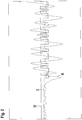
- Figure 2 shows the relevant time-dependent signal curves that are relevant for the detection of barcodes B.
- I denotes the analog received signal present at the output of the receiver 7.
- This analog received signal is differentiated in an FIR filter, which can be part of the evaluation unit.
- the differentiated received signal is in Figure 2 marked with II.
- the digital receive signal designated III in FIG. 2 is obtained, the signal sequence of which contains the coding of the code elements of the bar code B, so that the bar code B can be decoded using this digital receive signal.
- the differentiated received signal is processed to eliminate noise components.
- Figure 3 a section of the temporal received signal curve of the differentiated received signal.
- noise signal components in an area B there are useful signal components, namely a minimum and a maximum, which correspond to the light / dark transitions of code elements of the bar code B.
- the evaluation described below relates to a scan, that is to say the differentiated received signals which are obtained during a scanning of the scanning area with the transmitted light beams 4. This evaluation is repeated in the same way for all scans.
- the differentiated temporal received signal curve is examined for pairs of valid minima and maxima.
- the search for a valid minimum is in Figure 3 , based on a received signal value E 1 , that is, a first value of the differentiated received signal curve.
- the current received signal value E 1 is adopted as the initial value for a current minimum.
- the current threshold value S min forms an abort criterion for the search for the valid minimum.
- the subsequent received signal value E 4 is greater than the previous received signal value E 3 .
- the current minimum is set to the received signal value E 6 .
- the received signal value E n1 this received signal value finally exceeds the current threshold value S min , so that the minimum search is ended, the current minimum is accepted and stored at E 6 as a valid minimum L 1 , and a maximum search is started.
- the received signal values always increase continuously up to the received signal value E n2 , so that the new received signal value is always adopted for the definition of the current maximum and the current threshold value S max .
- the last determined current maximum is then adopted as the valid maximum H 1 .
- a further search for minima and maxima then takes place in a further method step, corresponding to the first method step.
- a modified threshold ⁇ is used for this, which is obtained from an amplitude evaluation of the valid pairs of minima and maxima, as will be described below.
- the changed threshold ⁇ is constant. In general, the changed threshold ⁇ is greater than the threshold ⁇ 0 used as the initial value. With this changed threshold ⁇ , the minimum and maximum searches result in the stored pairs of valid minima and maxima the extreme values caused by noise (in Figure 3 these are the extreme values L 1 , H 1 , L 2 , H 2 ) of the extreme values originating from the barcode B (in Figure 3 these are the extreme values L 3 , H 3 ) separated and rejected.
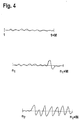
- the method for determining a constant changed threshold as in Figure 4 shown, an interval defined as a section in the stored sequence of the valid minima and maxima of a scan, which has a constant size.
- the size of the interval is adapted to the typical width of a barcode B, so that typically about ten pairs of extreme values fit into the interval.
- This interval is based on the first extreme value (upper diagram in Figure 4 ) with a fixed step size, which can be one in particular, within the sequence of the valid extreme values.
- the mean of the magnitudes of the amplitudes of the valid extreme values in this interval is formed for each position of the interval.
- the sequence that is used is the one that delivers the greatest mean value.
- the largest valid extreme value in terms of amount is then sought from this selected interval.
- the modified threshold ⁇ is then calculated from this. This is a fraction of the extreme value, which is preferably about a third.
- the received signals and differentiated received signals originating from these barcodes B vary considerably.
- the changed threshold is then selected as a function of time.
- a number of neighboring intervals is always considered together when the interval is pushed through.
- the number of adjacent intervals considered together is preferably three.
- the largest extreme value in terms of amount is sought, from which the changed threshold is then derived for this partial area formed by the combined intervals.
Landscapes
- Physics & Mathematics (AREA)
- Electromagnetism (AREA)
- Engineering & Computer Science (AREA)
- Health & Medical Sciences (AREA)
- General Health & Medical Sciences (AREA)
- Toxicology (AREA)
- Artificial Intelligence (AREA)
- Computer Vision & Pattern Recognition (AREA)
- General Physics & Mathematics (AREA)
- Theoretical Computer Science (AREA)
- Dc Digital Transmission (AREA)
- Optical Communication System (AREA)
Claims (9)
- Procédé de détection de codes à barres (B) au moyen d'un lecteur de code (1) qui comporte un émetteur (5) émettant des rayons lumineux d'émission (4), une unité de déviation et un récepteur (7) sur lequel les rayons lumineux d'émission (4) réfléchis par un code à barres (B) tombent sous forme de rayons lumineux de réception (6), dans lequel, au moyen de l'unité de déviation, les rayons lumineux émis (4) balayent périodiquement une zone de balayage à l'intérieur de chaque balayage, et dans lequel le lecteur de code (1) comporte une unité d'évaluation, caractérisé en ce que, dans l'unité d'évaluation destinée à détecter des codes à barres (B), les signaux reçus à la sortie du récepteur (7) sont évalués selon les étapes de procédé suivantes.• former le profil temporel différencié des signaux de réception pour chaque balayage,• déterminer les paires valides d'un minimum et d'un maximum suivant ce minimum dans le trajet du signal reçu d'un balayage,• dans lequel, lors d'une recherche d'un minimum, des valeurs successives de signaux reçus sont comparées et la valeur actuelle du signal reçu est adoptée comme minimum actuel si elle est inférieure à la valeur précédente du signal reçu, et dans lequel une valeur de seuil actuelle Smin est calculée à partir de la somme du minimum actuel et d'un seuil δ0, qui est prédéterminé comme valeur initiale, dans lequel la recherche du minimum est terminée lorsque la valeur actuelle du signal reçu est supérieure à la valeur de seuil actuelle Smin déterminée précédemment et le minimum actuel y est stocké comme minimum valide et une recherche d'un maximum y est lancée, et dans lequel des valeurs successives de signaux reçus sont comparées pendant une recherche d'un maximum et la valeur actuelle du signal reçu est adoptée comme maximum actuel si elle est supérieure à la valeur précédente du signal reçu, et dans lequel une valeur de seuil actuelle Smax est calculée à partir de la différence entre le maximum actuel et le ou un autre seuil δ0, dans lequel la recherche du maximum est terminée lorsque la valeur actuelle du signal reçu est inférieure à la valeur de seuil actuelle déterminée précédemment, et ensuite le maximum actuel est stocké comme un maximum valide et la recherche d'un minimum est alors lancée,• déterminer au moins un seuil modifié δ à partir des minima et maxima valides stockés de cette analyse, dans lequel le seuil modifié δ est défini comme une certaine fraction du montant d'une valeur extrême sélectionnée et dans lequel sa valeur est contractuellement supérieure à sa valeur initiale,• déterminer les paires finales de paires consécutives de minima et de maxima en répétant la recherche des minima et des maxima avec le seuil modifié δ pour les paires de minima et de maxima valides enregistrées du balayage,• décoder le code à barres (B) sur la base des paires finales déterminées de minima et de maxima pour le balayage respectif et d'un signal de réception numérique dérivé de celui-ci, qui contient le codage des éléments de code du code à barres.
- Procédé selon la revendication 1, caractérisé en ce qu'une paire valide d'un minimum et d'un maximum n'est présente que si l'intervalle de temps entre eux se situe dans une plage de valeurs nominales.
- Procédé selon l'une des revendications 1 ou 2, caractérisée en ce que le même seuil est utilisé pour rechercher les minima et les maxima.
- Procédé selon l'une des revendications 1 à 3, caractérisé en ce que le seuil modifié δ est constant pour un balayage.
- Procédé selon la revendication 4, caractérisé en ce que pour déterminer le seuil modifié δ, un intervalle est défini qui s'étend sur une section de la séquence de valeurs extrêmes valides de l'analyse, en ce que l'intervalle commence d'abord à la première valeur extrême de l'analyse et est ensuite décalé pas à pas, jusqu'à ce que l'intervalle se termine à la dernière valeur extrême de l'analyse, en ce que pour chaque position de l'intervalle, la moyenne des valeurs extrêmes dans l'intervalle est formée, et en ce qu'une valeur extrême pour calculer le seuil modifié δ est choisie dans l'intervalle pour lequel la moyenne est maximale.
- Procédé selon l'une des revendications 1 à 3, caractérisée en ce que différents seuils modifiés δ sont sélectionnés pour différentes zones au sein d'un balayage.
- Procédé selon la revendication 6, caractérisé en ce que pour déterminer les seuils modifiés δ, un intervalle s'étendant sur une section de la séquence des valeurs extrêmes valides du balayage est défini, en ce que l'intervalle commence d'abord à la première valeur extrême du balayage et est ensuite décalé pas à pas, jusqu'à ce que l'intervalle se termine à la dernière valeur extrême de l'analyse, qu'un certain nombre d'intervalles positionnés de manière adjacente sont combinés pour former une sous-gamme de l'analyse, que la valeur extrême la plus élevée en termes de quantité est recherchée dans les intervalles d'une sous-gamme et que le seuil modifié δ pour cette sous-gamme est calculé à partir de cette valeur extrême.
- Procédé selon la revendication 7, caractérisée en ce que les différentes sous-zones sont contiguës sans discontinuité et s'étendent sur l'ensemble de l'analyse.
- Procédé selon l'une des revendications 1 à 8, caractérisé en ce que les signaux reçus présents à la sortie du récepteur (7) sont différenciés au moyen d'un filtre FIR.
Applications Claiming Priority (1)
| Application Number | Priority Date | Filing Date | Title |
|---|---|---|---|
| EP16194276 | 2016-10-18 |
Publications (2)
| Publication Number | Publication Date |
|---|---|
| EP3312761A1 EP3312761A1 (fr) | 2018-04-25 |
| EP3312761B1 true EP3312761B1 (fr) | 2020-07-15 |
Family
ID=57153345
Family Applications (1)
| Application Number | Title | Priority Date | Filing Date |
|---|---|---|---|
| EP16194637.1A Active EP3312761B1 (fr) | 2016-10-18 | 2016-10-19 | Procédé de détection de codes-barres au moyen d'un lecteur de code |
Country Status (1)
| Country | Link |
|---|---|
| EP (1) | EP3312761B1 (fr) |
Cited By (1)
| Publication number | Priority date | Publication date | Assignee | Title |
|---|---|---|---|---|
| DE202025100910U1 (de) | 2025-02-20 | 2026-07-02 | Leuze Electronic Gmbh + Co. Kg | Codeleser |
Families Citing this family (1)
| Publication number | Priority date | Publication date | Assignee | Title |
|---|---|---|---|---|
| US11314959B1 (en) | 2021-06-30 | 2022-04-26 | Datalogic Ip Tech S.R.L. | System and method for identification and quantification of types of failure in automated reading of barcodes |
Family Cites Families (3)
| Publication number | Priority date | Publication date | Assignee | Title |
|---|---|---|---|---|
| US4468704A (en) * | 1982-10-28 | 1984-08-28 | Xerox Corporation | Adaptive thresholder |
| US5861616A (en) * | 1996-10-01 | 1999-01-19 | Mustek Systems, Inc. | Method and device for recognizing a waveform of an analog signal |
| DE19945837C2 (de) * | 1999-09-24 | 2003-11-27 | Leuze Electronic Gmbh & Co Kg | Optoelektronische Vorrichtung zum Erkennen von Barcodes |
-
2016
- 2016-10-19 EP EP16194637.1A patent/EP3312761B1/fr active Active
Non-Patent Citations (1)
| Title |
|---|
| None * |
Cited By (1)
| Publication number | Priority date | Publication date | Assignee | Title |
|---|---|---|---|---|
| DE202025100910U1 (de) | 2025-02-20 | 2026-07-02 | Leuze Electronic Gmbh + Co. Kg | Codeleser |
Also Published As
| Publication number | Publication date |
|---|---|
| EP3312761A1 (fr) | 2018-04-25 |
Similar Documents
| Publication | Publication Date | Title |
|---|---|---|
| DE69124996T2 (de) | Strichcodeleser mit grosser tiefenschärfe | |
| EP1953504A1 (fr) | Procédé de saisie optique d'un objet et dispositif optoélectronique | |
| DE69634584T2 (de) | Optische Abtaster | |
| EP3892955B1 (fr) | Caméra et procédé de détection des données d'image | |
| DE3602008C2 (fr) | ||
| EP4310443A1 (fr) | Palpeur optique de triangulation | |
| DE19936440A1 (de) | Optoelektronische Vorrichtung | |
| EP3312761A1 (fr) | Procédé de détection de codes-barres au moyen d'un lecteur de code | |
| EP4030337B1 (fr) | Capteur optique et procédé de détection des codes | |
| EP3926519B1 (fr) | Capteur optique et procédé de détection de codes | |
| EP2520952B1 (fr) | Capteur optoélectronique et procédé de détection d'objet | |
| EP2735887A1 (fr) | Dispositif d'enregistrement optique | |
| EP3070496A1 (fr) | Dispositif de balayage a polygone et procede de detection d'objets | |
| EP0720762B1 (fr) | Dispositif optoelectronique pour identifier des marques de contraste | |
| DE3783524T2 (de) | Binaerkodierschaltung fuer ocr. | |
| DE69732565T2 (de) | Vorrichtung und Verfahren zum Lesen eines optischen Codes | |
| DE10113641B4 (de) | Optoelektronische Vorrichtung | |
| EP0686290B1 (fr) | Dispositif opto-electronique de reconnaissance de symboles de code a barres | |
| DE102014116852A1 (de) | Optoelektronischer Sensor mit einem Empfangselement | |
| EP1130533B1 (fr) | Scanner | |
| EP1197910A2 (fr) | Dispositif et méthode pour la reconnaissance de codes | |
| EP3312760B1 (fr) | Capteur optique | |
| EP4390758B1 (fr) | Capteur optique | |
| DE19504912C2 (de) | Verfahren und Vorrichtung zum Erkennen von Barcode-Symbolen | |
| DE102012104131A1 (de) | Automatische anpassung der ansteuerung eines insbesondere für fahrerassistenzsysteme vorgesehenen imagers an äussere einflüsse |
Legal Events
| Date | Code | Title | Description |
|---|---|---|---|
| PUAI | Public reference made under article 153(3) epc to a published international application that has entered the european phase |
Free format text: ORIGINAL CODE: 0009012 |
|
| STAA | Information on the status of an ep patent application or granted ep patent |
Free format text: STATUS: THE APPLICATION HAS BEEN PUBLISHED |
|
| STAA | Information on the status of an ep patent application or granted ep patent |
Free format text: STATUS: REQUEST FOR EXAMINATION WAS MADE |
|
| AK | Designated contracting states |
Kind code of ref document: A1 Designated state(s): AL AT BE BG CH CY CZ DE DK EE ES FI FR GB GR HR HU IE IS IT LI LT LU LV MC MK MT NL NO PL PT RO RS SE SI SK SM TR |
|
| AX | Request for extension of the european patent |
Extension state: BA ME |
|
| 17P | Request for examination filed |
Effective date: 20180326 |
|
| RBV | Designated contracting states (corrected) |
Designated state(s): AL AT BE BG CH CY CZ DE DK EE ES FI FR GB GR HR HU IE IS IT LI LT LU LV MC MK MT NL NO PL PT RO RS SE SI SK SM TR |
|
| GRAP | Despatch of communication of intention to grant a patent |
Free format text: ORIGINAL CODE: EPIDOSNIGR1 |
|
| STAA | Information on the status of an ep patent application or granted ep patent |
Free format text: STATUS: GRANT OF PATENT IS INTENDED |
|
| RAP1 | Party data changed (applicant data changed or rights of an application transferred) |
Owner name: LEUZE ELECTRONIC GMBH + CO. KG |
|
| INTG | Intention to grant announced |
Effective date: 20200507 |
|
| GRAS | Grant fee paid |
Free format text: ORIGINAL CODE: EPIDOSNIGR3 |
|
| GRAA | (expected) grant |
Free format text: ORIGINAL CODE: 0009210 |
|
| STAA | Information on the status of an ep patent application or granted ep patent |
Free format text: STATUS: THE PATENT HAS BEEN GRANTED |
|
| AK | Designated contracting states |
Kind code of ref document: B1 Designated state(s): DE |
|
| RBV | Designated contracting states (corrected) |
Designated state(s): DE |
|
| REG | Reference to a national code |
Ref country code: DE Ref legal event code: R096 Ref document number: 502016010498 Country of ref document: DE |
|
| REG | Reference to a national code |
Ref country code: DE Ref legal event code: R097 Ref document number: 502016010498 Country of ref document: DE |
|
| PLBE | No opposition filed within time limit |
Free format text: ORIGINAL CODE: 0009261 |
|
| STAA | Information on the status of an ep patent application or granted ep patent |
Free format text: STATUS: NO OPPOSITION FILED WITHIN TIME LIMIT |
|
| 26N | No opposition filed |
Effective date: 20210416 |
|
| P01 | Opt-out of the competence of the unified patent court (upc) registered |
Free format text: CASE NUMBER: UPC_APP_0013772_3312761/2025 Effective date: 20251118 |
|
| PGFP | Annual fee paid to national office [announced via postgrant information from national office to epo] |
Ref country code: DE Payment date: 20251021 Year of fee payment: 10 |