EP3312846A1 - Festelektrolytherstellungsverfahren - Google Patents
Festelektrolytherstellungsverfahren Download PDFInfo
- Publication number
- EP3312846A1 EP3312846A1 EP16811727.3A EP16811727A EP3312846A1 EP 3312846 A1 EP3312846 A1 EP 3312846A1 EP 16811727 A EP16811727 A EP 16811727A EP 3312846 A1 EP3312846 A1 EP 3312846A1
- Authority
- EP
- European Patent Office
- Prior art keywords
- solid electrolyte
- lithium
- raw materials
- producing
- amorphous
- Prior art date
- Legal status (The legal status is an assumption and is not a legal conclusion. Google has not performed a legal analysis and makes no representation as to the accuracy of the status listed.)
- Withdrawn
Links
Images


Classifications
-
- C—CHEMISTRY; METALLURGY
- C01—INORGANIC CHEMISTRY
- C01B—NON-METALLIC ELEMENTS; COMPOUNDS THEREOF; METALLOIDS OR COMPOUNDS THEREOF NOT COVERED BY SUBCLASS C01C
- C01B25/00—Phosphorus; Compounds thereof
- C01B25/14—Sulfur, selenium, or tellurium compounds of phosphorus
-
- B—PERFORMING OPERATIONS; TRANSPORTING
- B01—PHYSICAL OR CHEMICAL PROCESSES OR APPARATUS IN GENERAL
- B01J—CHEMICAL OR PHYSICAL PROCESSES, e.g. CATALYSIS OR COLLOID CHEMISTRY; THEIR RELEVANT APPARATUS
- B01J19/00—Chemical, physical or physico-chemical processes in general; Their relevant apparatus
- B01J19/18—Stationary reactors having moving elements inside
- B01J19/20—Stationary reactors having moving elements inside in the form of helices, e.g. screw reactors
-
- H—ELECTRICITY
- H01—ELECTRIC ELEMENTS
- H01B—CABLES; CONDUCTORS; INSULATORS; SELECTION OF MATERIALS FOR THEIR CONDUCTIVE, INSULATING OR DIELECTRIC PROPERTIES
- H01B13/00—Apparatus or processes specially adapted for manufacturing conductors or cables
-
- H—ELECTRICITY
- H01—ELECTRIC ELEMENTS
- H01M—PROCESSES OR MEANS, e.g. BATTERIES, FOR THE DIRECT CONVERSION OF CHEMICAL ENERGY INTO ELECTRICAL ENERGY
- H01M10/00—Secondary cells; Manufacture thereof
- H01M10/05—Accumulators with non-aqueous electrolyte
- H01M10/056—Accumulators with non-aqueous electrolyte characterised by the materials used as electrolytes, e.g. mixed inorganic/organic electrolytes
- H01M10/0561—Accumulators with non-aqueous electrolyte characterised by the materials used as electrolytes, e.g. mixed inorganic/organic electrolytes the electrolyte being constituted of inorganic materials only
- H01M10/0562—Solid materials
-
- H—ELECTRICITY
- H01—ELECTRIC ELEMENTS
- H01M—PROCESSES OR MEANS, e.g. BATTERIES, FOR THE DIRECT CONVERSION OF CHEMICAL ENERGY INTO ELECTRICAL ENERGY
- H01M6/00—Primary cells; Manufacture thereof
- H01M6/14—Cells with non-aqueous electrolyte
- H01M6/18—Cells with non-aqueous electrolyte with solid electrolyte
-
- C—CHEMISTRY; METALLURGY
- C01—INORGANIC CHEMISTRY
- C01P—INDEXING SCHEME RELATING TO STRUCTURAL AND PHYSICAL ASPECTS OF SOLID INORGANIC COMPOUNDS
- C01P2002/00—Crystal-structural characteristics
- C01P2002/70—Crystal-structural characteristics defined by measured X-ray, neutron or electron diffraction data
- C01P2002/72—Crystal-structural characteristics defined by measured X-ray, neutron or electron diffraction data by d-values or two theta-values, e.g. as X-ray diagram
-
- C—CHEMISTRY; METALLURGY
- C01—INORGANIC CHEMISTRY
- C01P—INDEXING SCHEME RELATING TO STRUCTURAL AND PHYSICAL ASPECTS OF SOLID INORGANIC COMPOUNDS
- C01P2006/00—Physical properties of inorganic compounds
- C01P2006/40—Electric properties
-
- H—ELECTRICITY
- H01—ELECTRIC ELEMENTS
- H01M—PROCESSES OR MEANS, e.g. BATTERIES, FOR THE DIRECT CONVERSION OF CHEMICAL ENERGY INTO ELECTRICAL ENERGY
- H01M2220/00—Batteries for particular applications
- H01M2220/30—Batteries in portable systems, e.g. mobile phone, laptop
-
- H—ELECTRICITY
- H01—ELECTRIC ELEMENTS
- H01M—PROCESSES OR MEANS, e.g. BATTERIES, FOR THE DIRECT CONVERSION OF CHEMICAL ENERGY INTO ELECTRICAL ENERGY
- H01M2300/00—Electrolytes
- H01M2300/0017—Non-aqueous electrolytes
- H01M2300/0065—Solid electrolytes
- H01M2300/0068—Solid electrolytes inorganic
-
- Y—GENERAL TAGGING OF NEW TECHNOLOGICAL DEVELOPMENTS; GENERAL TAGGING OF CROSS-SECTIONAL TECHNOLOGIES SPANNING OVER SEVERAL SECTIONS OF THE IPC; TECHNICAL SUBJECTS COVERED BY FORMER USPC CROSS-REFERENCE ART COLLECTIONS [XRACs] AND DIGESTS
- Y02—TECHNOLOGIES OR APPLICATIONS FOR MITIGATION OR ADAPTATION AGAINST CLIMATE CHANGE
- Y02E—REDUCTION OF GREENHOUSE GAS [GHG] EMISSIONS, RELATED TO ENERGY GENERATION, TRANSMISSION OR DISTRIBUTION
- Y02E60/00—Enabling technologies; Technologies with a potential or indirect contribution to GHG emissions mitigation
- Y02E60/10—Energy storage using batteries
Definitions
- the present invention relates to a solid electrolyte production method.
- PTL 1 As a method for producing a solid electrolyte for use in the solid electrolyte layer, there are known a method of mechanically milling raw materials using a planetary ball mill or the like, a method of melting raw materials at a high temperature and the like (for example, PTL 1).
- PTLs 2, 3 As a method excellent in industrial productivity and mass-productivity, a method of making raw materials kept in contact with each other in a state where a hydrocarbon-based organic solvent has been added thereto, or mechanically milling them has been proposed (for example, PTLs 2, 3).
- PTL 4 discloses a solid electrolyte glass production apparatus equipped with a screw and having a compression part for compressing raw materials and a melting part for heating the compressed raw materials to be a molten body (for example, PTL 4).
- the mechanical milling method or the method of melting raw materials at a high temperature described in PTL 1 requires a special equipment, and therefore cannot be said to be suitable for productivity and mass-productivity.
- the method using a hydrocarbon-based organic solvent described in PTLs 2 and 3 uses an organic solvent and therefore requires a step of drying and recovering the solvent, and as the case may be, the process is often complicated.
- the production apparatus described in PTL 4 requires a high temperature of 600°C or higher for making the compressed raw materials a molten body, for example, 800°C or so in the case of producing Li 3 PS 4 (PTL 4, paragraph [0031]). Consequently, a driving part of screws in the production apparatus is, though made of high-chromium steel, exposed to the high pressure in the compression part and to the high temperature in the melting part, therefore resulting in reduction in the material strength. In addition, the apparatus needs a special heating equipment and needs a large energy consumption amount, that is, the apparatus could not be said to have excellent productivity and mass-productivity.
- the present invention has been made in consideration of the situation as above, and its object is to provide a method for producing amorphous and crystalline solid electrolytes excellent in productivity and mass-productivity, as well as a multi-axial kneading machine.
- the present inventors have assiduously studied for the purpose of solving the above-mentioned problems and, as a result, have found that the problems can be solved by the following invention.
- amorphous and crystalline solid electrolytes with excellent productivity and mass-productivity.
- the solid electrolyte production method of the present invention includes reacting two or more kinds of solid raw materials using a multi-axial kneading machine to give an amorphous solid electrolyte.
- the amorphous solid electrolyte is one whose X-ray diffraction pattern in X-ray diffractometry is a halo pattern substantially not having any other peak than the materials-derived peaks, irrespective of the presence or absence of solid electrolyte raw materials-derived peaks.
- the solid raw materials for use in the production method of the present invention may be any ones that contain elements generally constituting amorphous solid electrolytes.
- the conductive species capable of expressing ion conductivity at least one element selected from alkali metals such as lithium, sodium, potassium, rubidium, cesium, francium, etc., and alkaline earth metals such as beryllium, magnesium, calcium, strontium, barium, radium and the like is preferred, and in consideration of the ability of high ion conductivity and the ability to realize high output power of batteries, an alkali metal such as lithium, sodium, potassium, rubidium, cesium, francium, etc., and beryllium are more preferred, and lithium is especially preferred.
- solid raw materials containing at least one element selected from alkali metals such as lithium, sodium, potassium, rubidium, cesium, francium, etc., and alkaline earth metals such as beryllium, magnesium, calcium, strontium, barium, radium and the like are preferred; solid raw materials containing at least one element selected from an alkali metal such as lithium, sodium, potassium, rubidium, cesium, francium, etc., and beryllium are more preferred; and solid raw materials containing a lithium element are especially preferred.
- the amorphous solid electrolytes include, as mentioned below, oxide solid electrolytes, sulfide solid electrolytes, etc., and in consideration of the ability to realize high output power of batteries, sulfide solid electrolytes are preferred.
- the solid raw materials are preferably those containing a lithium element, a phosphorus element and a sulfur element. Using such solid raw materials, solid electrolytes containing a lithium element, a phosphorus element and a sulfur element corresponding to the elements contained in the solid raw materials are obtained.
- lithium compounds such as lithium sulfide (Li 2 S), lithium oxide (Li 2 O), lithium carbonate (Li 2 CO 3 ), etc., and a lithium metal elementary substance is preferred; and as the lithium compound, lithium sulfide (Li 2 S) is especially preferred.
- Lithium sulfide may be used with no specific limitation, but one having a high purity is preferred. Lithium sulfide may be produced, for example, according to the methods described in JP 7-330312 A , JP 9-283156 A , JP 2010-163356 A , and JP 2011-84438 A .
- lithium hydroxide and hydrogen sulfide are reacted in a hydrocarbon-based organic solvent at 70 to 300°C to give lithium hydrosulfide, and then the reaction liquid is processed for hydrogen sulfide removal to give lithium sulfide ( JP 2010-163356 A ).
- lithium hydroxide and hydrogen sulfide may be reacted in a water-based solvent at 10 to 100°C to give lithium hydrosulfide, and then the reaction liquid may be processed for hydrogen sulfide removal to give lithium sulfide ( JP 2011-84438 A ).
- lithium hydroxide may be reacted with hydrogen sulfide to give lithium sulfide.
- the reaction temperature in this case is, for example, 20 to 300°C, 100 to 250°C, or 120 to 240°C.
- the solid raw materials containing a phosphorus element for example, at least one of phosphorus sulfides such as diphosphorus trisulfide (P 2 S 3 ), diphosphorus pentasulfide (P 2 S 5 ), etc., silicon sulfide (SiS 2 ), germanium sulfide (GeS 2 ), boron sulfide (B 2 S 3 ), gallium sulfide (Ga 2 S 3 ), tin sulfide (SnS or SnS 2 ), aluminum sulfide (Al 2 S 3 ), zinc sulfide (ZnS), phosphorus compounds such as sodium phosphate (Na 3 PO 4 ), etc., and phosphorus elementary substance is preferred.
- phosphorus sulfides such as diphosphorus trisulfide (P 2 S 3 ), diphosphorus pentasulfide (P 2 S 5 ), etc.
- the phosphorus compound is preferably a phosphorus sulfide, and diphosphorus pentasulfide (P 2 S 5 ) is more preferred.
- Phosphorus compounds such as diphosphorus pentasulfide (P 2 S 5 ) and a phosphorus elementary substance may be any ones that are industrially produced and commercially available, with no specific limitation for use herein.
- the solid raw materials containing a lithium element, a phosphorus element and a sulfur element preferably contain at least one of a lithium compound and a lithium metal elementary substance, and at least one of a phosphorus compound and a phosphorus elementary substance.
- a combination of a lithium compound and a phosphorus compound is preferred, a combination of a lithium compound and a phosphorus sulfide is more preferred, a combination of a lithium sulfide and a phosphorus sulfide is even more preferred, and a combination of a lithium sulfide and a diphosphorus pentasulfide is especially more preferred.
- the amount of the lithium element-containing solid raw materials and the phosphorus element-containing solid raw materials to be used may be adequately determined based on the desired solid electrolyte.
- the ratio of Li 2 S to the total of Li 2 S and P 2 S 5 is, from the viewpoint of obtaining an amorphous solid electrolyte having high chemical stability, preferably within a range of 68 to 82 mol%, more preferably within a range of 70 to 80 mol%, even more preferably within a range of 72 to 78 mol%, and especially more preferably within a range of 74 to 76 mol%.
- the solid raw materials further contain at least one kind of halogen elements such as fluorine (F), chlorine (Cl), bromine (Br) and iodine (I), more preferably at least one of chlorine (Cl), bromine (Br) and iodine (I), even more preferably at least one of bromine (Br) and iodine (I).
- halogen elements such as fluorine (F), chlorine (Cl), bromine (Br) and iodine (I), more preferably at least one of chlorine (Cl), bromine (Br) and iodine (I), even more preferably at least one of bromine (Br) and iodine (I).
- a halogen-containing compound represented by the following general formula (1) is preferably contained.
- M represents sodium (Na), lithium (Li), boron (B), aluminum (Al), silicon (Si), phosphorus (P), sulfur (S), germanium (Ge), arsenic (As), selenium (Se), tin (Sn), antimony (Sb), tellurium (Te), lead (Pb), bismuth (Bi), or those formed of the element with an oxygen element and a sulfur element bonding thereto.
- Lithium (Li) or phosphorus (P) is preferred, and lithium (Li) is especially preferred.
- X represents a halogen element selected from fluorine (F), chlorine (Cl), bromine (Br) and iodine (I).
- m is an integer of 1 or 2
- m is an integer of 1 to 10.
- X's may be the same or different.
- SiBrCl 3 to be mentioned below m is 4, and X are different elements of Br and Cl.
- examples of the halogen-containing compound represented by the above general formula (1) include sodium halides such as NaI, NaF, NaCl, NaBr, etc.; lithium halides such as LiF, LiCl, LiBr, LiI, etc., boron halides such as BCl 3 , BBr 3 , BI 3 , etc., aluminum halides such as AlF 3 , AlBr 3 , AlI 3 , AlCl 3 , etc., silicon halides such as SiF 4 , SiCl 4 , SiCl 3 , Si 2 Cl 6 , SiBr 4 , SiBrCl 3 , SiBr 2 Cl 2 , SiI 4 , etc.
- sodium halides such as NaI, NaF, NaCl, NaBr, etc.
- lithium halides such as LiF, LiCl, LiBr, LiI, etc.
- boron halides such as BCl 3 , BBr 3 , BI 3 , etc
- phosphorus halides such as PF 3 , PF 5 , PCl 3 , PCl 5 , POCl 3 , PBr 3 , POBr 3 , PI 3 , P 2 Cl 4 , P 2 I 4 , etc.
- sulfur halides such as SF 2 , SF 4 , SF 6 , S 2 F 10 , SCl 2 , S 2 Cl 2 , S 2 Br 2 , etc.
- germanium halides such as GeF 4 , GeCl 4 , GeBr 4 , GeI 4 , GeF 2 , GeCl 2 , GeBr 2 , GeI 2 , etc.
- arsenic halides such as AsF 3 , AsCl 3 , AsBr 3 , AsI 3 , AsF 5 , etc.
- selenium halides such as SeF 4 , SeF 6 , SeCl 2 , SeCl 4 , Se 2 Br 2 , SeBr 4 , etc.
- lithium halides such as lithium chloride (LiCl), lithium bromide (LiBr), lithium iodide (LiI), etc.
- phosphorus halides such as phosphorus pentachloride (PCl 5 ), phosphorus trichloride (PCl 3 ), phosphorus pentabromide (PBr 5 ), phosphorus tribromide (PBr 3 ), etc. are preferred.
- lithium halides such as lithium chloride (LiCl), lithium bromide (LiBr), lithium iodide (LiI), etc., and phosphorus tribromide (PBr 3 ) are preferred; and lithium halides such as lithium chloride (LiCl), lithium bromide (LiBr), lithium iodide (LiI), etc. are more preferred; and lithium bromide (LiBr) and lithium iodide (LiI) are especially preferred.
- the halogen-containing compound one alone or two or more kinds of the above-mentioned compounds may be used either singly or as combined. Namely, at least one of the above-mentioned compounds may be used.
- the total amount to be used of lithium bromide (LiBr) and lithium iodide (LiI) in the solid raw materials for use for production of an amorphous solid electrolyte is not specifically limited so far as the ratio can give a desired amorphous solid electrolyte, but for example, the amount preferably falls within a range of 3 to 40 mol%, more preferably within a range of 3 to 35 mol%, even more preferably within a range of 3 to 30 mol%.
- the amount may fall within a range of 5 mol% or more and 28 mol% or less, a range of 8 mol% or more and 28 mol% or less, a range of 10 mol% or more and 28 mol% or less, a range of 12 mol% or more and 28 mol% or less, or a range of 15 mol% or more and 28 mol% or less.
- the proportion of lithium bromide (LiBr) to the total of lithium bromide (LiBr) and lithium iodide (LiI) is not specifically limited, and any desired ratio may be employed, but the proportion is preferably such that an Li ion conductivity not lower than the same level relative to the amorphous solid electrolyte (amorphous solid electrolyte as a comparative subject) prepared in the same manner except that lithium bromide (LiBr) is substituted with lithium iodide (LiI) could be obtained, and more preferably such that an Li ion conductivity higher than the comparative subject, amorphous solid electrolyte can be obtained.
- the proportion of the above-mentioned lithium bromide (LiBr) is, for example, within a range of 1 to 99 mol%, more preferably within a range of 5 to 75 mol%.
- the proportion may fall within a range of 20 mol% or more and 75 mol% or less, or 40 mol% or more and 72 mol% or less, or 50 mol% or more and 70 mol% or less.
- the proportion of lithium iodide (LiI) in all the materials for use in production of the amorphous solid electrolyte is more than 3 mol% but less than 20 mol%, and the proportion of lithium bromide (LiBr) in all the materials is preferably 3 to 20 mol%.
- a corresponds to the total proportion of the above-mentioned LiI and LiBr
- b corresponds to the proportion of the above-mentioned LiBr
- c corresponds to the proportion of the above-mentioned Li 2 S.
- the particle size of the above-mentioned solid raw materials may be any particle size that each of the above-mentioned raw materials generally has with no specific limitation.
- the particle size of lithium sulfide may be 0.01 to 3 mm
- the particle size of diphosphorus pentasulfide may be 0.01 to 3 mm.
- the particle size of lithium bromide may be 0.01 to 3 mm
- the particle size of lithium iodide may be 0.01 to 3 mm.
- the particle size range of the solid raw materials for use in the present invention is broad, and using a multi-axial kneading machine, a solid electrolyte can be produced irrespective of the particle size of the solid raw materials.
- the mean particle size is a value to be measured using a laser diffractometric particle sizer (for example, Master Sizer 2000 manufactured by Malvern Instruments, Ltd.).
- the above-mentioned solid raw materials may be used directly as they are, but may be used in the form of a slurry thereof with an organic solvent.
- an organic solvent is used as little as possible, and using solid raw materials directly as they are, that is, using them in a solid state is preferred in reaction.
- the organic solvent for use in such a case includes an aprotic solvent such as an aprotic polar solvent or an aprotic non-polar solvent.
- aprotic polar organic compound examples include amide compounds, lactam compounds, urea compounds, organic sulfur compounds, cyclic organic phosphorus compounds, etc.
- the aprotic non-polar solvent includes a solvent composed of carbon atoms and hydrogen atoms alone, for example, a hydrocarbon-based organic solvent such as a saturated hydrocarbon, an unsaturated hydrocarbon, an aromatic hydrocarbon, etc.
- a hydrocarbon-based organic solvent such as a saturated hydrocarbon, an unsaturated hydrocarbon, an aromatic hydrocarbon, etc.
- the carbon number of the saturated hydrocarbon and the unsaturated hydrocarbon is, for example, 3 or more and 50 or less
- the carbon number of the aromatic hydrocarbon is, for example, 6 or more and 50 or less.
- the saturated hydrocarbon includes hexane, pentane, 2-ethylhexane, heptane, octane, decane, cyclohexane, methylcyclohexane, IP Solvent 1016 (manufactured by Idemitsu Kosan Co., Ltd.), IP Solvent 1620 (manufactured by Idemitsu Kosan Co., Ltd.), etc.; the unsaturated hydrocarbon includes hexene, heptene, cyclohexene, etc.; and the aromatic hydrocarbon includes toluene, xylene, ethylbenzene, decalin, 1,2,3,4-tetrahydronaphthalene, Ipsol 100 (manufactured by Idemitsu Kosan Co., Ltd.), Ipsol 150 (manufactured by Idemitsu Kosan Co., Ltd.), etc.
- any other solvent may be added to the above-mentioned hydrocarbon-based organic solvent.
- ketones such as acetone, methyl ethyl ketone, etc.
- ethers such as tetrahydrofuran, etc.
- alcohols such as ethanol, butanol, etc.
- esters such as ethyl acetate, etc.
- halogenohydrocarbons such as dichloromethane, chlorobenzene, etc.
- one alone or two or more kinds of these organic solvents may be used either singly or as combined.
- the amount thereof to be used is preferably such that the total amount of the solid raw materials to be added relative to 1 liter of the organic solvent could be 0.001 to 1 kg, more preferably 0.005 to 0.5 kg, more preferably 0.01 to 0.3 kg.
- the amount of the organic solvent to be used is preferably as small as possible.
- the multi-axial kneading machine for use in the production method of the present invention is, for example, provided with a casing and two or more rotary shafts arranged to run through the casing in the longitudinal direction and equipped with paddles (screw blades) along the axial direction, in which one end in the longitudinal direction of the casing is provided with a supply port for solid raw materials and the other end is provided with a discharge port, and the machine is not specifically limited in point of the other constitution.
- two or more rotary movements may interact with each other to form shearing stress, and the shearing stress may be imparted to the solid raw materials moving from the supply port toward the discharge port along the rotary axis, and the raw materials could be thereby reacted.
- Fig. 1 is a plane view cut at the center of a rotary shaft of a kneading machine
- Fig. 2 is a plan view cut vertically to the rotary shaft in a part provided with paddles of the rotary shaft.
- the multi-axial kneading machine shown in Fig. 1 is a biaxial kneading machine provided with a casing 1 provided with a supply port 2 at one end and a discharge port 3 at the other end, and two rotary shafts 4a and 4b arranged to run through in the longitudinal direction of the casing 1.
- the rotary shafts 4a and 4b each are provided with paddles 5a and 5b, respectively.
- Solid raw materials enter the casing 1 via the supply port 2, and are reacted with each other as given shearing stress at the paddles 5a and 5b, and the resultant reaction product, that is, an amorphous solid electrolyte is discharged out via the discharge port 3.
- the number of rotary shafts 4 (4a, 4b) may be 2 or more, and in consideration of general versatility, the number is preferably 2 to 4, more preferably 2.
- the rotary shafts 4 may be parallel shafts that are parallel to each other, or may be oblique shafts, and the rotating direction of the rotary shafts may be in the same direction or in different directions.
- the rotating direction is preferably in different directions, or in the case where a self-cleaning effect of sweeping up the solid raw materials and the reaction product in the casing and preventing them from staying in the casing is considered to be important, the same direction may be selected for the rotating direction.
- Paddles 5 are fixed to the rotary shafts for kneading solid raw materials, and are referred to as screw blades.
- the cross-sectional form thereof includes, as shown in Fig. 2 , a nearly triangle form modified from a regular triangle by making each side thereof have a uniformly convexed arc, and in addition thereto, a circular form, an oval form, a nearly square form, etc., and may additionally include modifications based on these forms and having a partial cutout.
- each paddle may be fixed to the rotary shaft at a different angle, as shown in Fig. 2 .
- the paddles may be engaging ones or non-engaging ones, but for obtaining a better kneading effect, engaging paddles may be selected.
- the multi-axial kneading machine may be provided with screws 6 (6a, 6b) on the side of the supply port 2 as shown in Fig. 1 , and for preventing the reaction product obtained via the paddles 5 from staying inside the casing, reverse screws 7 (7a, 7b) may be arranged on the side of the discharge port 3 as shown in Fig. 1 .
- a commercially-available kneading machine may be used as the multi-axial kneading machine.
- Examples of the commercially-available multi-axial kneading machines include KRC Kneader, KRC Junior (manufactured by Kurimoto, Ltd.), etc., and depending on the kinds of solid raw materials and on the desired scale, the machine may be adequately selected.
- the reaction temperature for the solid raw materials is preferably not higher than the crystallization temperature of the amorphous solid electrolyte obtained by the reaction of the solid raw materials.
- the crystallization temperature in the present invention is a crystallization temperature of an amorphous solid electrolyte, and can be confirmed and measured through differential thermal analysis (DTA).
- DTA differential thermal analysis
- a sample is heated at a heating condition of 10°C/min for differential thermal analysis (DTA), in which a temperature indicating the exothermic peak to be detected on the lowermost side is the crystallization temperature of the sample.
- the crystallization temperature differs depending on the kind and the compositional ratio of the elements constituting the resultant amorphous solid electrolyte and on the difference in the structure thereof, and the crystallization temperature of an Li 2 S-P 2 S 5 -based amorphous solid electrolyte falls, for example, within a range of 210 to 340°C, the crystallization temperature of an Li 2 S-P 2 S 5 -LiBr-based amorphous solid electrolyte falls, for example, within a range of 170 to 290°C, the crystallization temperature of an Li 2 S-P 2 S 5 -LiI-based amorphous solid electrolyte falls, for example, within a range of 140 to 260°C, and the crystallization temperature of an Li 2 S-P 2 S 5 -LiI-LiBr-based amorphous solid electrolyte temperature falls, for example, within a range of 140 to 260°C.
- the reaction temperature is, from the viewpoint of obtaining an amorphous solid electrolyte, preferably one not higher than the crystallization temperature thereof, more preferably the crystallization temperature -150 to -1°C, even more preferably -100 to -5°C, especially preferably -80 to -30°C.
- a method for controlling the reaction temperature for solid raw materials a method generally used in a multi-axial kneading machine may be employed.
- the method includes a method of controlling the supply amount of solid raw materials, a method of controlling the driving power, a method of controlling the rotation number, a method of cooling the system, etc.
- the method of controlling the supply amount of solid raw materials in general, when the supply amount is reduced, the temperature tends to lower.
- the method of controlling driving power in general, when the driving power is reduced, the temperature tends to lower.
- the method of controlling the rotation number in general, when the rotation number is decreased, the temperature tends to lower.
- the reaction of solid raw materials is carried out while cooling from the viewpoint of obtaining an amorphous solid electrolyte.
- the cooling method may be any of a water-cooling method or an air-cooling method, but in consideration of cooling efficiency, water-cooling is preferred.
- cooling may be attained by a method of arranging a water-cooling jacket around the casing of a multi-axial kneading machine, or a method of introducing cooling water to run through the rotary shaft for in-shaft cooling.
- the rotation number of the rotary shaft of the multi-axial kneading machine differs, depending on the kind and the compositional ratio of the elements constituting the amorphous solid electrolyte to be produced and on the difference in the structure thereof, and therefore could not be indiscriminately stated, but is preferably 40 to 300 rpm, more preferably 40 to 250 rpm, even more preferably 40 to 200 rpm.
- the amorphous solid electrolyte to be obtained may change when brought into contact with water or oxygen, and therefore, supply and reaction of the solid raw materials as well as discharge of the reaction product are preferably carried out in an inert gas atmosphere.
- the inert gas includes nitrogen, argon, etc.
- the reaction of solid raw materials is carried out in a dry atmosphere, for example, preferably in an atmosphere at the dew point - 90°C or higher and -40°C or lower, more preferably in an atmosphere at the dew point - 90°C or higher and -45°C or lower, even more preferably at the dew point - 90°C or higher and -50°C or lower.
- a method of arranging the multi-axial kneading machine in a glove box, or a method of arranging the multi-axial kneading machine in a dry room may be employed.
- a method of continuously supplying the above-mentioned inert gas into the casing of the multi-axial kneading machine can realize the above.
- the casing of the multi-axial kneading machine may be provided with a supply port and a discharge port for an inert gas.
- the reaction time for the solid raw materials varies depending on the kind and the compositional ratio of the elements to constitute the amorphous solid electrolyte to be obtained, on the difference in the structure thereof, and on the temperature at the reaction, and therefore may be adequately controlled.
- the time is 5 minutes to 50 hours, more preferably 10 minutes to 15 hours, even more preferably 1 to 12 hours.
- the reaction product discharged out through the discharge port may be again supplied thereinto through the supply port depending on the degree of the reaction procedure to thereby further carry out the reaction.
- the degree of reaction procedure may be known by the change of the peaks derived from the solid electrolyte raw materials, and at the time when the peaks could be detected no more, it may be considered that the reaction has fully proceeded.
- the amorphous solid electrolyte obtained according to the production method of the present invention includes a solid electrolyte that contains, for example, at least one element selected from alkali metals such as lithium, sodium, potassium, rubidium, cesium, francium, etc., and alkaline earth metals such as beryllium, magnesium, calcium, strontium, barium, radium, etc., as a conductive species.
- alkali metals such as lithium, sodium, potassium, rubidium, cesium, francium, etc.
- alkaline earth metals such as beryllium, magnesium, calcium, strontium, barium, radium, etc.
- an alkali metal such as lithium, sodium, potassium, rubidium, cesium, francium, etc., and beryllium are preferred, and lithium is especially preferred.
- the amorphous solid electrolyte includes an amorphous oxide solid electrolyte, an amorphous sulfide solid electrolyte, etc., and in consideration of the ability of high ion conductivity and the ability to realize high output power of batteries, an amorphous sulfide solid electrolyte is preferred.
- amorphous sulfide solid electrolyte examples include an amorphous sulfide solid electrolyte containing a lithium element, a phosphorus element and a sulfur element, an amorphous sulfide solid electrolyte containing a lithium element, a phosphorus element, a sulfur element and a halogen element, an amorphous sulfide solid electrolyte containing a lithium element, a phosphorus element, a sulfur element and a bromine element, an amorphous sulfide solid electrolyte containing a lithium element, a phosphorus element, a sulfur element and an iodine element, and an amorphous sulfide solid electrolyte containing a lithium element, a phosphorus element, a sulfur element, a bromine element and an iodine element.
- the amorphous sulfide solid electrolyte includes Li 2 S-P 2 S 5 , Li 2 S-P 2 S 5 -LiI, Li 2 S-P 2 S 5 -LiCl, Li 2 S-P 2 S 5 -LiBr, Li 2 S-P 2 S 5 -LiI-LiBr, Li 2 S-P 2 S 5 -Li 2 O, Li 2 S-P 2 S 5 -Li 2 O-LiI, Li 2 S-SiS 2 , Li 2 S-SiS 2 -LiI, Li 2 S-SiS 2 -LiBr, Li 2 S-SiS 2 -LiCl, Li 2 S-SiS 2 -B 2 S 3 -LiI, Li 2 S-SiS 2 -P 2 S 5 -LiI, Li 2 S-B 2 S 3 , Li 2 S-P 2 S 5 -Z m S n (m and n each are a
- the amorphous oxide solid electrolyte includes Li 2 O-B 2 O 3 -P 2 O 5 , Li 2 O-SiO 2 , LiLaTaO (for example, Li 5 La 3 Ta 2 O 12 ), LiLaZrO (for example, Li 7 La 3 Zr 2 O 12 ), LiBaLaTaO (for example, Li 6 BaLa 2 Ta 2 O 12 ), Li 1+x Si x P 1-x O 4 (0 ⁇ x ⁇ 1, for example, Li 3.6 Si 0.6 P 0.4 O 4 ), Li 1+x Al x Ge 2-x (PO 4 ) 3 (0 ⁇ x ⁇ 2), Li 1+x Al x Ti 2-x (PO 4 ) 3 (0 ⁇ x ⁇ 2), Li 3 PO (4-3/2x) N x (0 ⁇ x ⁇ 1), etc.
- the kind of the elements constituting the amorphous solid electrolyte obtained according to the production method of the present invention can be identified, for example, by an ICP emission spectrometer.
- An example of the shape of the amorphous solid electrolyte obtained in the present invention is a granular one, though not specifically limited thereto.
- the mean particle size (D 50 ) of the granular amorphous solid electrolyte is, for example, within a range of 0.1 to 50 ⁇ m.
- the mean particle size (D 50 ) is a particle size to reach 50% of all the particles in sequential cumulation from the smallest particles in drawing the particle size distribution cumulative curve, and the volume distribution can be determined, for example, using a laser diffraction/scattering particle size distribution measuring apparatus.
- a material whose X-ray diffraction pattern in X-ray diffractmetry is a halo pattern substantially not showing any other peak than the materials-derived peaks irrespective of the presence or absence of solid electrolyte raw materials-derived peaks, that is, an amorphous solid electrolyte can be obtained, and by heat-treating it for crystallization, a crystalline solid electrolyte can be obtained.
- the production method for the crystalline solid electrolyte of the present invention includes producing a solid electrolyte according to the above-mentioned production method followed by heating the solid electrolyte.
- the crystalline solid electrolyte is a solid electrolyte material whose X-ray diffraction pattern in X-ray diffractometry gives a solid electrolyte-derived peak, irrespective of the presence or absence of solid electrolyte raw materials-derived peaks.
- the crystalline solid electrolyte contains a crystal structure derived from the solid electrolyte, in which a part of the crystal structure may be a crystal structure derived from the solid electrolyte, or all the crystal structure may be a crystal structure derived from the solid electrolyte.
- the crystalline solid electrolyte may partly contain an amorphous solid electrolyte so far as it has the above-mentioned X-ray diffraction pattern.
- the crystalline solid electrolyte includes a crystalline oxide solid electrolyte, a crystalline sulfide solid electrolyte, etc. From the viewpoint of the ability of high ion conductivity and the ability to realize high output power of batteries, a crystalline sulfide solid electrolyte is preferred.
- the crystalline sulfide solid electrolyte includes a crystalline sulfide solid electrolyte containing a lithium element, a phosphorus element and a sulfur element, a crystalline sulfide solid electrolyte containing a lithium element, a phosphorus element, a sulfur element and a halogen element, a crystalline sulfide solid electrolyte containing a lithium element, a phosphorus element, a sulfur element and a bromine element, a crystalline sulfide solid electrolyte containing a lithium element, a phosphorus element, a sulfur element and an iodine element, and a crystalline sulfide solid electrolyte containing a lithium element, a phosphorus element, a sulfur element, a bromine element and an iodine element.
- the crystal structure of the crystalline solid electrolyte includes an Li 3 PS 4 crystal structure, an Li 4 P 2 S 6 crystal structure, an Li 7 PS 6 crystal structure, an Li 7 P 3 S 11 crystal structure, an Li 4-x Ge 1-x P x S 4 -based thio-LISICON Region II-type crystal structure (see Kanno, et al., Journal of The Electrochemical Society, 148 (7) A742-746 (2001 )), a crystal structure similar to the Li 4-x Ge 1-x P x S 4 -based thio-LISICON Region II-type crystal structure (see Solid State Ionics, 177 (2006), 2721-2725 ), etc.
- the crystal structure of the crystalline solid electrolyte also includes an argyrodite-type crystal structure.
- the argyrodite-type crystal structure include an Li 7 PS 6 crystal structure; a crystal structure represented by a compositional formula Li 7-x P 1-y Si y S 6 or Li 7+x P 1-y Si y S 6 (x is -0.6 to 0.6, y is 0.1 to 0.6) which has a structure skeleton of Li 7 PS 6 and in which a part of P is substituted with Si; a crystal structure represented by Li 7-x-2y PS 6-x-y Cl x (0.8 ⁇ x ⁇ 1.7, 0 ⁇ y ⁇ -0.25x + 0.5); a crystal structure represented by Li 7-x PS 6-x Ha x (Ha represents Cl or Br, x is preferably 0.2 to 1.8).
- the crystal structure represented by a compositional formula Li 7-x P 1-y Si y S 6 or Li 7+x P 1-y Si y S 6 (x is -0.6 to 0.6, y is 0.1 to 0.6), which has the above-mentioned structure skeleton of Li 7 PS 6 and in which a part of P is substituted with Si, is a cubic crystal or a rhombic crystal, and is preferably a cubic crystal, and in X-ray diffractometry using a CuK ⁇ ray, the crystal structure gives peaks appearing mainly at 2 ⁇ 15.5°, 18.0°, 25.0°, 30.0°, 31.4°, 45.3°, 47.0°, and 52.0°.
- These peak positions may vary within a range of ⁇ 0.5°.
- the heat treatment temperature is preferably within a range of ⁇ 40°C from the peak top, as the origination, of the exothermic peak detected on the lowermost temperature side in differential thermal analysis (DTA) thereof at a heating condition of 10°C/min using a differential thermal analyzer (DTA device), more preferably ⁇ 30°C, even more preferably ⁇ 20°C.
- DTA differential thermal analysis
- the heat treatment time may be any time in which the desired crystalline solid electrolyte can be obtained but is, for example, preferably within a range of 1 minute or more and 24 hours or less, more preferably within a range of 1 minute or more and 10 hours or less.
- the heat treatment is carried out in an inert gas atmosphere (for example, nitrogen atmosphere, argon atmosphere), or in a reduced-pressure atmosphere (especially in vacuum).
- an inert gas atmosphere for example, nitrogen atmosphere, argon atmosphere
- a reduced-pressure atmosphere especially in vacuum
- the heat treatment method is not specifically limited.
- a method of using a vacuum heating device, an argon gas atmosphere furnace, a firing furnace or the like may be employed.
- the amorphous solid electrolyte obtained according to the production method of the present invention, and the crystalline solid electrolyte obtained by heat treatment of the solid electrolyte have a high ion conductivity and excellent battery performance, and are therefore favorably used in batteries.
- the solid electrolyte using a lithium element as the conductive species is especially favorable.
- the solid electrolyte obtained according to the production method of the present invention may be used in a positive electrode layer or a negative electrode layer, or may also be used in an electrolyte layer. Each layer may be produced according to a known method.
- the above-mentioned battery preferably uses a collector in addition to the positive electrode layer, the electrolyte layer and the negative electrode layer, and the collector may be any known one.
- a layer formed by coating Au, Pt, Al, Ti, Cu or the like capable of reacting with the above-mentioned solid electrolyte, with Au or the like may be used.
- the production method for an inorganic material of the present invention includes reacting two or more kinds of solid raw materials using a multi-axial kneading machine to give an amorphous inorganic material.
- the solid raw materials may be any ones that react with each other to give an amorphous inorganic material, and examples thereof include a zinc sulfide-type light emitting material, a molybdenum sulfide-type and vanadium alloy-type thermoelectric conversion materials, etc.
- the same one as that used in the above-mentioned production method for the solid electrolyte of the present invention may be employed.
- the temperature at the reaction of the solid raw materials is preferably not higher than the crystallization temperature of the amorphous inorganic material obtained by the reaction of the solid raw materials, and the other reaction conditions are the same as those in the above-mentioned solid electrolyte production method, and by heat-treating the resultant amorphous inorganic material, a crystalline inorganic material can be obtained like in the above-mentioned solid electrolyte production method.
- two or more kinds of solid raw materials may be reacted using a generalized machine such as a multi-axial kneading machine to produce a large variety of inorganic materials in a simplified manner with excellent productivity and mass-productivity.
- the multi-axial kneading machine of the present invention is used for production of an amorphous solid electrolyte according to the production method for a solid electrolyte of the present invention that includes reacting two or more kinds of solid raw materials.
- the structure and the use conditions for the multi-axial kneading machine of the present invention are the same as those described hereinabove in the section of the above-mentioned solid electrolyte production method of the present invention.
- the lead distance was about 60 cm.
- the purity of lithium sulfide was measured by analysis with hydrochloric acid titration and silver nitrate titration. Specifically, the lithium sulfide powder obtained in Production Example was metered in a glove box (dew point: about -100°C, nitrogen atmosphere), dissolved in water, measured using a potentiometric titrator ("COM-980 (model number)", manufactured by Hiranuma Sangyo Co., Ltd.), and calculated.
- COM-980 model number
- a feeder (Micron Feeder (product name)", manufactured by Aishin Nano Technologies Co., Ltd.), and a biaxial kneading machine ("KRC Junior (product name)", paddle diameter: ⁇ 8 mm, manufactured by Kurimoto, Ltd.) were arranged.
- the resultant reaction product was analyzed through powdery X-ray diffractometry (XRD), and as shown in Fig. 3 , the X-ray diffraction spectrum thereof represents a halo pattern with few peaks of lithium sulfide (Li 2 S) and diphosphorus pentasulfide (P 2 S 5 ), from which it is confirmed that the reaction product is an amorphous solid electrolyte.
- XRD powdery X-ray diffractometry
- the amorphous solid electrolyte obtained in this Example was subjected to differential thermal analysis (DTA) at a heating rate of 10°C/min using a differential thermal analyzer (DTA device), and the crystallization temperature (Tc) thereof was 230°C.
- DTA differential thermal analysis
- DTA device differential thermal analyzer
- a reaction product was obtained in the same manner as in Example 1 except that the mean motor torque was 0.8 Nm (load ratio: 60%).
- the temperature at the outer surface of the casing of the kneading machine during kneading was at most 90°C.
- the resultant reaction product was analyzed through powdery X-ray diffractometry (XRD), in which crystallization peaks ( ⁇ Li 3 PS 4 , etc.) relating to the solid electrolyte-derived crystal structure were detected, and partial crystallization was confirmed.
- XRD powdery X-ray diffractometry
- the ion conductivity was 2 ⁇ 10 -4 S/cm.
- the solid raw materials were a mixture of 2.78 g of lithium sulfide (Li 2 S), 4.435 g of diphosphorus pentasulfide (P 2 S 5 ), 1.425 g of lithium iodide (LiI), and 1.385 g of lithium bromide (LiBr) (Li 2 S:P 2 S 5 :LiI:Li
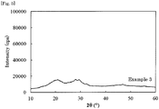
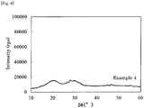
- the resultant reaction product was analyzed through powdery X-ray diffractometry (XRD), and as shown in Fig. 4 , the X-ray diffraction spectrum thereof represents a halo pattern with few peaks of lithium sulfide (Li 2 S), diphosphorus pentasulfide (P 2 S 5 ) and lithium iodide (LiI) though giving a small peak of lithium bromide (LiBr), from which it is confirmed that the reaction product is an amorphous solid electrolyte.
- the reaction product was heat-treated at 200°C for 3 hours, and the ion conductivity of the resultant product measured according to the above-mentioned method was 4 ⁇ 10 -3 S/cm.
- the temperature at the outer surface of the casing of the kneading machine during kneading was at most 40°C.
- the amorphous solid electrolyte obtained in this Example was subjected to differential thermal analysis (DTA) at a heating rate of 10°C/min using a differential thermal analyzer (DTA device), and the glass crystallization temperature (Tc) thereof was 170°C.
- DTA differential thermal analysis
- DTA device differential thermal analyzer
- a reaction product was obtained in the same manner as in Example 2 except that the mean motor torque was 0.8 Nm (load ratio: 60%).
- the temperature at the outer surface of the casing of the kneading machine during kneading was at most 80°C.
- the resultant reaction product was analyzed through powdery X-ray diffractometry (XRD), in which crystallization peaks (thio-LISICON Region II, etc.) relating to the solid electrolyte-derived crystal structure were detected, and partial crystallization was confirmed.
- XRD powdery X-ray diffractometry
- the product was heat-treated at 200°C for 3 hours, and the ion conductivity of the resultant product measured according to the above-mentioned method was 3 ⁇ 10 -3 S/cm.
- a reaction product was obtained in the same manner as in Example 2, except that, in Example 2, a cooling jacket was arranged around the casing part of the kneading machine and a cooling medium at -5°C was circulated therethrough to cool the casing part, and the mean motor torque was 0.8 Nm (load ratio: 60%).
- the resultant reaction product was analyzed through powdery X-ray diffractometry (XRD), and as shown in Fig. 5 , the X-ray diffraction spectrum thereof represents a halo pattern with few peaks of lithium sulfide (Li 2 S), diphosphorus pentasulfide (P 2 S 5 ) and lithium iodide (LiI) though giving a small peak of lithium bromide (LiBr), from which it is confirmed that the reaction product is an amorphous solid electrolyte.
- the reaction product was heat-treated at 200°C for 3 hours, and the ion conductivity of the resultant product measured according to the above-mentioned method was 4 ⁇ 10 -3 S/cm.
- the temperature at the outer surface of the casing of the kneading machine during kneading was at most 10°C.
- the amorphous solid electrolyte obtained from the raw materials used in this Example was subjected to differential thermal analysis (DTA) at a heating rate of 10°C/min using a differential thermal analyzer (DTA device), and the measured crystallization temperature (Tc) thereof was 167°C.
- DTA differential thermal analysis
- Li 2 S lithium sulfide
- P 2 S 5 diphosphorus pentasulfide
- LiBr lithium bromide
- the resultant reaction product was analyzed through powdery X-ray diffractometry (XRD), and as shown in Fig. 6 , the X-ray diffraction spectrum thereof represents a halo pattern with few peaks of lithium sulfide (Li 2 S) and diphosphorus pentasulfide (P 2 S 5 ) though giving a small peak of lithium bromide (LiBr), from which it is confirmed that the reaction product is an amorphous solid electrolyte.
- XRD powdery X-ray diffractometry
- the tendency of the reaction temperature to change can also be known from the temperature of the outer surface of the casing.
- the reaction temperature was controlled by changing the motor torque, but the temperature control is not limited in point of the method so far as the reaction temperature could be a temperature not higher than the crystallization temperature, that is, the temperature control is not limited to motor torque change.
- amorphous and crystalline solid electrolytes can be obtained with excellent productivity and mass-productivity.
- the amorphous and crystalline solid electrolytes have a high ion conductivity and have excellent battery performance and are therefore favorably used in batteries.
- Using a lithium element as the conductive species is especially preferred.
Landscapes
- Chemical & Material Sciences (AREA)
- Manufacturing & Machinery (AREA)
- Engineering & Computer Science (AREA)
- Organic Chemistry (AREA)
- Chemical Kinetics & Catalysis (AREA)
- Inorganic Chemistry (AREA)
- Electrochemistry (AREA)
- General Chemical & Material Sciences (AREA)
- General Physics & Mathematics (AREA)
- Condensed Matter Physics & Semiconductors (AREA)
- Physics & Mathematics (AREA)
- Conductive Materials (AREA)
- Secondary Cells (AREA)
- Primary Cells (AREA)
Applications Claiming Priority (2)
| Application Number | Priority Date | Filing Date | Title |
|---|---|---|---|
| JP2015122371 | 2015-06-17 | ||
| PCT/JP2016/068009 WO2016204253A1 (ja) | 2015-06-17 | 2016-06-16 | 固体電解質の製造方法 |
Publications (3)
| Publication Number | Publication Date |
|---|---|
| EP3312846A1 true EP3312846A1 (de) | 2018-04-25 |
| EP3312846A8 EP3312846A8 (de) | 2018-06-20 |
| EP3312846A4 EP3312846A4 (de) | 2018-12-26 |
Family
ID=57546087
Family Applications (1)
| Application Number | Title | Priority Date | Filing Date |
|---|---|---|---|
| EP16811727.3A Withdrawn EP3312846A4 (de) | 2015-06-17 | 2016-06-16 | Festelektrolytherstellungsverfahren |
Country Status (5)
| Country | Link |
|---|---|
| US (1) | US20180155198A1 (de) |
| EP (1) | EP3312846A4 (de) |
| JP (1) | JPWO2016204253A1 (de) |
| CN (1) | CN107710347A (de) |
| WO (1) | WO2016204253A1 (de) |
Cited By (1)
| Publication number | Priority date | Publication date | Assignee | Title |
|---|---|---|---|---|
| EP3505500A4 (de) * | 2016-08-23 | 2020-07-29 | Tokyo Institute of Technology | Sulfidfeststoffelektrolyt |
Families Citing this family (14)
| Publication number | Priority date | Publication date | Assignee | Title |
|---|---|---|---|---|
| JP6384404B2 (ja) * | 2015-06-01 | 2018-09-05 | トヨタ自動車株式会社 | 複合活物質粉体の製造装置、及び、複合活物質粉体の製造方法 |
| JP6679736B2 (ja) | 2016-09-12 | 2020-04-15 | 出光興産株式会社 | 硫化物固体電解質 |
| JP6763808B2 (ja) * | 2017-03-14 | 2020-09-30 | 出光興産株式会社 | 固体電解質の製造方法 |
| KR102507008B1 (ko) * | 2017-12-20 | 2023-03-06 | 현대자동차주식회사 | 단일 원소로부터 유래된 아지로다이트형 결정구조를 갖는 전고체 전지용 황화물계 고체전해질 및 이의 제조방법 |
| JP7047485B2 (ja) * | 2018-03-12 | 2022-04-05 | トヨタ自動車株式会社 | 硫化物固体電解質 |
| KR102151511B1 (ko) * | 2018-03-12 | 2020-09-03 | 미쓰이금속광업주식회사 | 황화물계 고체 전해질 입자 |
| JP7319900B2 (ja) * | 2018-12-05 | 2023-08-02 | 出光興産株式会社 | アルジロダイト型結晶構造を有する固体電解質の製造方法 |
| WO2020137392A1 (ja) * | 2018-12-26 | 2020-07-02 | パナソニックIpマネジメント株式会社 | 固体電解質材料およびそれを用いた電池 |
| CN110563013A (zh) * | 2019-08-26 | 2019-12-13 | 浙江工业大学 | 一种硫化铝的球磨合成方法 |
| JP7226256B2 (ja) * | 2019-11-12 | 2023-02-21 | トヨタ自動車株式会社 | 硫化物固体電解質材料の製造方法 |
| CN114730651B (zh) * | 2019-11-21 | 2025-08-08 | 出光兴产株式会社 | 硫化物固体电解质的制造方法 |
| JP7790346B2 (ja) * | 2020-07-07 | 2025-12-23 | Agc株式会社 | リチウムイオン二次電池に用いられる硫化物系固体電解質、及びその製造方法並びにリチウムイオン二次電池 |
| CN113506918B (zh) * | 2021-07-09 | 2022-12-13 | 郑州新世纪材料基因组工程研究院有限公司 | 一种无机固态电解质的制备方法 |
| JP7155360B1 (ja) | 2021-08-02 | 2022-10-18 | 株式会社日本製鋼所 | 反応装置、反応システム、材料製造システム、電池用材料製造システム、電池製造システム、反応生成物製造方法、電池用材料製造方法および電池製造方法 |
Family Cites Families (9)
| Publication number | Priority date | Publication date | Assignee | Title |
|---|---|---|---|---|
| DE1199737B (de) * | 1961-12-07 | 1965-09-02 | Schwan Bleistift Fabrik | Misch- und Knetmaschine |
| DE3412258A1 (de) * | 1984-04-02 | 1985-10-10 | Werner & Pfleiderer, 7000 Stuttgart | Gleichdrall-doppelschneckenkneter mit knetscheiben |
| DE19713072A1 (de) * | 1997-03-27 | 1998-10-01 | Basf Ag | Verfahren zur Herstellung von Formkörpern für Lithiumionenbatterien |
| US6079865A (en) * | 1998-04-10 | 2000-06-27 | Hp Intellectual Corp. | Electric mixer |
| JP2007220377A (ja) * | 2006-02-15 | 2007-08-30 | Ohara Inc | 固体電解質及び固体電解質の製造方法 |
| JP5561023B2 (ja) * | 2010-08-25 | 2014-07-30 | トヨタ自動車株式会社 | 硫化物固体電解質材料の製造方法 |
| JP2012199003A (ja) * | 2011-03-18 | 2012-10-18 | Toyota Motor Corp | スラリー、固体電解質層の製造方法および電極活物質層の製造方法 |
| JP5652322B2 (ja) * | 2011-05-17 | 2015-01-14 | 日本ゼオン株式会社 | 全固体二次電池の製造方法 |
| WO2014010169A1 (ja) * | 2012-07-12 | 2014-01-16 | 出光興産株式会社 | イオン伝導性物質の製造方法、イオン伝導性物質、結晶化イオン伝導性物質及び電池 |
-
2016
- 2016-06-16 EP EP16811727.3A patent/EP3312846A4/de not_active Withdrawn
- 2016-06-16 JP JP2017524837A patent/JPWO2016204253A1/ja not_active Withdrawn
- 2016-06-16 CN CN201680035330.1A patent/CN107710347A/zh active Pending
- 2016-06-16 WO PCT/JP2016/068009 patent/WO2016204253A1/ja not_active Ceased
- 2016-06-16 US US15/737,624 patent/US20180155198A1/en not_active Abandoned
Cited By (2)
| Publication number | Priority date | Publication date | Assignee | Title |
|---|---|---|---|---|
| EP3505500A4 (de) * | 2016-08-23 | 2020-07-29 | Tokyo Institute of Technology | Sulfidfeststoffelektrolyt |
| US11152641B2 (en) | 2016-08-23 | 2021-10-19 | Tokyo Institute Of Technology | Sulfide solid electrolyte |
Also Published As
| Publication number | Publication date |
|---|---|
| EP3312846A4 (de) | 2018-12-26 |
| WO2016204253A1 (ja) | 2016-12-22 |
| JPWO2016204253A1 (ja) | 2018-04-05 |
| CN107710347A (zh) | 2018-02-16 |
| US20180155198A1 (en) | 2018-06-07 |
| EP3312846A8 (de) | 2018-06-20 |
Similar Documents
| Publication | Publication Date | Title |
|---|---|---|
| US20180155198A1 (en) | Solid electrolyte production method | |
| JP7102453B2 (ja) | 硫化物固体電解質 | |
| US10781101B2 (en) | Solid electrolyte production method using a multi-axial kneading machine | |
| JP6683363B2 (ja) | 固体電解質の製造方法 | |
| JP6936073B2 (ja) | 硫化物固体電解質 | |
| US10020535B2 (en) | Method for producing sulfide solid electrolyte | |
| US11264642B2 (en) | Sulfide solid electrolyte | |
| EP3598462A1 (de) | Verfahren zur herstellung eines feststoffelektrolyten | |
| JP6798797B2 (ja) | 固体電解質の製造方法 | |
| JP2023152966A (ja) | 硫化物固体電解質、その製造方法、電極合材及びリチウムイオン電池 | |
| JP2018101593A (ja) | 固体電解質の製造方法 | |
| KR20250037765A (ko) | 유리 고체 전해질 및 리튬 이온 전지 |
Legal Events
| Date | Code | Title | Description |
|---|---|---|---|
| PUAI | Public reference made under article 153(3) epc to a published international application that has entered the european phase |
Free format text: ORIGINAL CODE: 0009012 |
|
| 17P | Request for examination filed |
Effective date: 20171215 |
|
| AK | Designated contracting states |
Kind code of ref document: A1 Designated state(s): AL AT BE BG CH CY CZ DE DK EE ES FI FR GB GR HR HU IE IS IT LI LT LU LV MC MK MT NL NO PL PT RO RS SE SI SK SM TR |
|
| AX | Request for extension of the european patent |
Extension state: BA ME |
|
| RAP1 | Party data changed (applicant data changed or rights of an application transferred) |
Owner name: IDEMITSU KOSAN CO.,LTD. |
|
| DAV | Request for validation of the european patent (deleted) | ||
| DAX | Request for extension of the european patent (deleted) | ||
| RIC1 | Information provided on ipc code assigned before grant |
Ipc: H01M 6/18 20060101ALI20181115BHEP Ipc: H01B 13/00 20060101AFI20181115BHEP Ipc: C01B 25/14 20060101ALI20181115BHEP Ipc: H01M 10/0562 20100101ALI20181115BHEP Ipc: B01J 19/20 20060101ALI20181115BHEP |
|
| A4 | Supplementary search report drawn up and despatched |
Effective date: 20181123 |
|
| 17Q | First examination report despatched |
Effective date: 20190813 |
|
| STAA | Information on the status of an ep patent application or granted ep patent |
Free format text: STATUS: THE APPLICATION HAS BEEN WITHDRAWN |
|
| 18W | Application withdrawn |
Effective date: 20191105 |