EP3312856A1 - Tranformator mit wicklungsträger mit kühlfunktionalität - Google Patents
Tranformator mit wicklungsträger mit kühlfunktionalität Download PDFInfo
- Publication number
- EP3312856A1 EP3312856A1 EP16194557.1A EP16194557A EP3312856A1 EP 3312856 A1 EP3312856 A1 EP 3312856A1 EP 16194557 A EP16194557 A EP 16194557A EP 3312856 A1 EP3312856 A1 EP 3312856A1
- Authority
- EP
- European Patent Office
- Prior art keywords
- winding
- cooling
- cooling fluid
- transformer
- winding body
- Prior art date
- Legal status (The legal status is an assumption and is not a legal conclusion. Google has not performed a legal analysis and makes no representation as to the accuracy of the status listed.)
- Withdrawn
Links
Images





Classifications
-
- H—ELECTRICITY
- H01—ELECTRIC ELEMENTS
- H01F—MAGNETS; INDUCTANCES; TRANSFORMERS; SELECTION OF MATERIALS FOR THEIR MAGNETIC PROPERTIES
- H01F27/00—Details of transformers or inductances, in general
- H01F27/28—Coils; Windings; Conductive connections
- H01F27/2876—Cooling
-
- H—ELECTRICITY
- H01—ELECTRIC ELEMENTS
- H01F—MAGNETS; INDUCTANCES; TRANSFORMERS; SELECTION OF MATERIALS FOR THEIR MAGNETIC PROPERTIES
- H01F27/00—Details of transformers or inductances, in general
- H01F27/08—Cooling; Ventilating
- H01F27/085—Cooling by ambient air
-
- H—ELECTRICITY
- H01—ELECTRIC ELEMENTS
- H01F—MAGNETS; INDUCTANCES; TRANSFORMERS; SELECTION OF MATERIALS FOR THEIR MAGNETIC PROPERTIES
- H01F27/00—Details of transformers or inductances, in general
- H01F27/28—Coils; Windings; Conductive connections
- H01F27/30—Fastening or clamping coils, windings, or parts thereof together; Fastening or mounting coils or windings on core, casing, or other support
- H01F27/306—Fastening or mounting coils or windings on core, casing or other support
Definitions
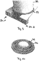
- Fig. 3 shows a perspective view of an example of the winding support 24 according to the present invention.
- first partial interior space and the second partial interior space and/or related channels may be used to guide cooling fluid, e.g. air, to different interior parts of the winding body 22, e.g., to spaces between a low voltage winding and a high voltage winding and further to a space between a low voltage winding and a magnetic core of the transformer 10.
- cooling fluid e.g. air
- the interior partition wall 34 also forms the mechanical bearing by being exposed to the exterior of the hollow traverse body 26 across the at least one cooling cutout 32-1 to 32-3.
- the interior partition wall 34 is only one option for supporting the winding body 22.
- the winding body 22 is supported by any type of mechanical bearing which is provided within the hollow traverse body 26 for exposure to the exterior of the hollow traverse body 26 in an subarea of the cooling cutout 32 which is intended for overlap with the at least one winding body 22.
- cutout section 32 is shown as segment of a circle in Fig. 3 the present invention is not restricted thereto. I.e., as long as the functionality of cooling fluid supply to the winding body 22 is achieved any other form may be suitably selected, e.g., triangular, rectangular, polygonal, ellipsoid, etc.
- one lower winding support 24 is attached to a lower core clamp to space the three winding bodies 22-1 to 22-3 and the lower core clamp.
- the transformer 10 may comprise two lower winding supports 24-1, 24-2 which are attached to two lower core clamps 16, 18 of the transformer 10.
- a blower unit or a fan may be used for supply of cooling fluid to the two lower winding supports 24-1, 24-2.
- one partial space of the hollow traverse body 26, e.g., the outer partial space may have a partition 50 for establishment of a dedicated cooling channel 52.
- the partition wall 34 comprises a cooling outlet 54 provided in relation to at least one predetermined cooled surface of the at least one winding body 22.
- a cooled surface and a related cooling fluid supply target point may be located to guide cooling fluid to an air gap provided around the circumference of the winding body 22, to the space between the high voltage winding 44 and the low voltage winding 46, and/or to the space between the low voltage winding and the magnetic core 48. The latter does not apply should the space between the magnetic core 48 and the low voltage winding be filled with casting compound.
- FIG. 9 shows one example of a basic configuration for the use of the winding support 24 according to the present invention it should be noted that also modifications are conceivable.
- dedicated cooling channels 52 may be provided with respect to only a subset of winding bodies in a multiphase transformer.
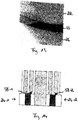
- Fig. 10 shows further details of a winding body 22, in particular with respect to a low voltage winding 46 and a high voltage winding 44 and related cooling channels.
- cooling channels as outlined above may as well be applied to such cooling channels being provided in either the high voltage winding 44 and/or the low voltage winding 46.
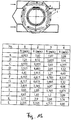
- Fig. 11 summarizes measurement results achievable with respect to a plurality of internal points of a winding body and with respect to the basic configuration of the winding support shown in Fig. 9 .
- measurement points are placed around the circumference of the winding body 22 according to A to L and further along the radial direction of the winding body as indicated by numerals 1 to 4, wherein 1 identifies a cooling channel in the high voltage winding 44, 2 identifies space between high voltage winding 44 and low voltage winding 46, 3 identifies a cooling channel in the low voltage winding, and 4 identifies a cooling channel between the low voltage winding 46 and the magnetic core 48.
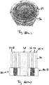
- the diameter of the envelope 56 is selected to fully extend across an air gap 55 formed around the circumference of the winding body 22.
- the interior partition wall 34 may have at least one spacer section 58-1, 58-2 extending to the exterior of the hollow traverse body 26 where the interior partition wall 34 crosses a cooling cutout 32.
- spacer sections 58-1, 58-2 allows to achieve increased separation between the bearing provided by the hollow traverse body 26 and the winding body and therefore for an improvement of convection with the hollow traverse body 26.
- An exemplary spacing achievable by spacer sections 58-1, 58-2 is in the range of 1 to 2 cm.
- Fig. 15 summarizes measurement results to illustrate improvements achievable with the optimization measures illustrated with respect to Fig. 12 to 14 .
- the cooling channels of the interior cooling plate 60 may be connected to outside supply pipes and/or supply hoses by use of liquid cooling fluid connections 62-1, 62-2.
- Fig. 18 shows a transformer system 64 according to the present invention.
- the transformer 10 using the winding support 24 according to the present invention is accommodated in a housing 66 and thermally coupled to a heat exchanger 68.
- a housing 66 and thermally coupled to a heat exchanger 68.
- the housing 66 An advantage of the provision of the housing 66 is that a distance between the transformer and grounded parts may be reduced significantly. This also allows for a more compact realization of the transformer system 64, e.g., within a gondola of a wind mill.
- the housing may be covered at it outer surface with a conductive or semi-conductive layer for an improved control of electric fields within the housing. This allows to further increase compactness of the overall design.
- a ventilator 70 is provided for establishment of a circulation of cooling fluid between the winding supports 24 of the transformer and the heat exchanger 70.
- a heat exchanger 68 is an option only.
- the convection of cooling fluid may as well be achieved by connecting the exchange openings of the winding supports to dedicated supply and discharge lines for cooling fluid to and from the winding supports 24.
- Fig. 19 shows a cross-sectional view through the transformer system 64 shown in Fig. 18 .
- the transformer system 64 further comprises at least one lower and upper winding support 24 as explained above with respect to Fig. 2 to 17 which is respectively attached to the lower core clamp(s) and/or the upper core clamp(s) to space the three winding bodies, the lower core clamp(s) and the upper core clamp(s).
- the winding supports 24 allow for exchange of cooling fluid with cooling channel(s) of the three winding bodies.
- the heat generated during cooling of the magnetic core may also be used for heating of components outside the transformer system, irrespective of whether the housing 66 is provided or not.
- the combined cooling fluid/liquid cooling allows for improved efficiency of the transformer system 64 and makes cooling by fans during no load operation of the transformer system 64 optional.
Landscapes
- Engineering & Computer Science (AREA)
- Power Engineering (AREA)
- Transformer Cooling (AREA)
Priority Applications (2)
| Application Number | Priority Date | Filing Date | Title |
|---|---|---|---|
| EP16194557.1A EP3312856A1 (de) | 2016-10-19 | 2016-10-19 | Tranformator mit wicklungsträger mit kühlfunktionalität |
| PCT/EP2017/073892 WO2018072964A1 (en) | 2016-10-19 | 2017-09-21 | Transformer with winding support having cooling functionality |
Applications Claiming Priority (1)
| Application Number | Priority Date | Filing Date | Title |
|---|---|---|---|
| EP16194557.1A EP3312856A1 (de) | 2016-10-19 | 2016-10-19 | Tranformator mit wicklungsträger mit kühlfunktionalität |
Publications (1)
| Publication Number | Publication Date |
|---|---|
| EP3312856A1 true EP3312856A1 (de) | 2018-04-25 |
Family
ID=57178300
Family Applications (1)
| Application Number | Title | Priority Date | Filing Date |
|---|---|---|---|
| EP16194557.1A Withdrawn EP3312856A1 (de) | 2016-10-19 | 2016-10-19 | Tranformator mit wicklungsträger mit kühlfunktionalität |
Country Status (2)
| Country | Link |
|---|---|
| EP (1) | EP3312856A1 (de) |
| WO (1) | WO2018072964A1 (de) |
Cited By (4)
| Publication number | Priority date | Publication date | Assignee | Title |
|---|---|---|---|---|
| EP3651350A1 (de) * | 2018-11-06 | 2020-05-13 | General Electric Company | System und verfahren zur windenergieerzeugung und zur übertragung in stromsysteme |
| EP3882934A1 (de) * | 2020-03-17 | 2021-09-22 | ABB Power Grids Switzerland AG | Isolator mit internen kühlkanälen |
| EP4489038A1 (de) * | 2023-07-04 | 2025-01-08 | Hitachi Energy Ltd | Transformatoranordnung mit einem luftkanalelement, luftkanalelement und kühlsystem zum kühlen eines transformators |
| KR20250150389A (ko) * | 2024-04-11 | 2025-10-20 | 에이치디현대일렉트릭 주식회사 | 몰드변압기용 클램프 및 이를 포함하는 몰드변압기용 냉각 시스템 |
Citations (7)
| Publication number | Priority date | Publication date | Assignee | Title |
|---|---|---|---|---|
| US3137829A (en) * | 1959-11-12 | 1964-06-16 | Gen Electric | Electrical apparatus |
| JPS5296313A (en) * | 1976-02-09 | 1977-08-12 | Hitachi Ltd | Oil-filled transformer |
| DE3341626A1 (de) * | 1983-11-17 | 1985-05-30 | May & Christe Gmbh, Transformatorenwerke, 6370 Oberursel | Luftgekuehlter transformator |
| JPS6081615U (ja) * | 1983-11-10 | 1985-06-06 | 富士電機株式会社 | 風冷乾式誘導電器 |
| JPS6249216U (de) * | 1985-09-17 | 1987-03-26 | ||
| US20150213940A1 (en) * | 2014-01-27 | 2015-07-30 | Hitachi, Ltd. | Static Apparatus |
| JP2015228442A (ja) * | 2014-06-02 | 2015-12-17 | 株式会社東芝 | ガス絶縁静止器 |
-
2016
- 2016-10-19 EP EP16194557.1A patent/EP3312856A1/de not_active Withdrawn
-
2017
- 2017-09-21 WO PCT/EP2017/073892 patent/WO2018072964A1/en not_active Ceased
Patent Citations (7)
| Publication number | Priority date | Publication date | Assignee | Title |
|---|---|---|---|---|
| US3137829A (en) * | 1959-11-12 | 1964-06-16 | Gen Electric | Electrical apparatus |
| JPS5296313A (en) * | 1976-02-09 | 1977-08-12 | Hitachi Ltd | Oil-filled transformer |
| JPS6081615U (ja) * | 1983-11-10 | 1985-06-06 | 富士電機株式会社 | 風冷乾式誘導電器 |
| DE3341626A1 (de) * | 1983-11-17 | 1985-05-30 | May & Christe Gmbh, Transformatorenwerke, 6370 Oberursel | Luftgekuehlter transformator |
| JPS6249216U (de) * | 1985-09-17 | 1987-03-26 | ||
| US20150213940A1 (en) * | 2014-01-27 | 2015-07-30 | Hitachi, Ltd. | Static Apparatus |
| JP2015228442A (ja) * | 2014-06-02 | 2015-12-17 | 株式会社東芝 | ガス絶縁静止器 |
Cited By (9)
| Publication number | Priority date | Publication date | Assignee | Title |
|---|---|---|---|---|
| EP3651350A1 (de) * | 2018-11-06 | 2020-05-13 | General Electric Company | System und verfahren zur windenergieerzeugung und zur übertragung in stromsysteme |
| US10826297B2 (en) | 2018-11-06 | 2020-11-03 | General Electric Company | System and method for wind power generation and transmission in electrical power systems |
| EP3882934A1 (de) * | 2020-03-17 | 2021-09-22 | ABB Power Grids Switzerland AG | Isolator mit internen kühlkanälen |
| WO2021185699A1 (en) * | 2020-03-17 | 2021-09-23 | Abb Power Grids Switzerland Ag | Insulator having internal cooling channels |
| KR20220136433A (ko) * | 2020-03-17 | 2022-10-07 | 히타치 에너지 스위처랜드 아게 | 내부 냉각 채널들을 가진 절연체 |
| US11715588B2 (en) | 2020-03-17 | 2023-08-01 | Hitachi Energy Switzerland Ag | Insulator having internal cooling channels |
| EP4489038A1 (de) * | 2023-07-04 | 2025-01-08 | Hitachi Energy Ltd | Transformatoranordnung mit einem luftkanalelement, luftkanalelement und kühlsystem zum kühlen eines transformators |
| WO2025008492A1 (en) * | 2023-07-04 | 2025-01-09 | Hitachi Energy Ltd | Transformer arrangement having an air duct element, air duct element, and cooling system for cooling a transformer |
| KR20250150389A (ko) * | 2024-04-11 | 2025-10-20 | 에이치디현대일렉트릭 주식회사 | 몰드변압기용 클램프 및 이를 포함하는 몰드변압기용 냉각 시스템 |
Also Published As
| Publication number | Publication date |
|---|---|
| WO2018072964A1 (en) | 2018-04-26 |
Similar Documents
| Publication | Publication Date | Title |
|---|---|---|
| EP3312856A1 (de) | Tranformator mit wicklungsträger mit kühlfunktionalität | |
| US9653955B2 (en) | Stator arrangement | |
| EP2518868B1 (de) | Kühlanordnung für eine elektrische Maschine | |
| CN101752958B (zh) | 水冷电机及电机冷却方法 | |
| US20100176670A1 (en) | Machine cooling scheme | |
| US8604899B2 (en) | Electrical transformer with diaphragm and method of cooling same | |
| US8040000B2 (en) | Stator cooling structure for superconducting rotating machine | |
| EP2806537B1 (de) | Rotierender elektrischer Generatorstator, rotierender elektrischer Generator mit diesem Stator und Windturbine mit diesem rotierenden elektrischen Generator | |
| EP3888105B1 (de) | Transformatorkühlsystem und transformatoranlage | |
| JP2018532365A (ja) | 冷却される流体静力学的なコンパクトユニット | |
| US3075103A (en) | Fluid cooled chill ring for canned motors | |
| US20160372985A1 (en) | Motor | |
| US20150256045A1 (en) | Multi-directional air cooling of a motor using radially mounted fan | |
| HK1252708A1 (en) | Transformer with winding support having cooling functionality | |
| EP2814144A1 (de) | Luft-Luft-Wärmetauscher | |
| US20240113598A1 (en) | Electrical machine | |
| EP3709317B1 (de) | Anordnung zur kühlung einer spule | |
| CN102447322B (zh) | 发电机,特别是用于风力涡轮机的发电机 | |
| CN215267827U (zh) | 一种高效的电机定子端部布油结构 | |
| US20250062660A1 (en) | Attachment cooler of a dynamo-electric machine with plate coolers | |
| EP2533404A1 (de) | Statoranordnung | |
| EP4199014A1 (de) | Statische elektrische induktionsvorrichtung und betriebsverfahren | |
| CN210006574U (zh) | 一种加快变压器油循环的电力变压器 | |
| JP7662257B2 (ja) | モールド型静止誘導機器 | |
| CN121310507A (zh) | 一种射频电源散热系统及射频电源 |
Legal Events
| Date | Code | Title | Description |
|---|---|---|---|
| PUAI | Public reference made under article 153(3) epc to a published international application that has entered the european phase |
Free format text: ORIGINAL CODE: 0009012 |
|
| 17P | Request for examination filed |
Effective date: 20161019 |
|
| AK | Designated contracting states |
Kind code of ref document: A1 Designated state(s): AL AT BE BG CH CY CZ DE DK EE ES FI FR GB GR HR HU IE IS IT LI LT LU LV MC MK MT NL NO PL PT RO RS SE SI SK SM TR |
|
| AX | Request for extension of the european patent |
Extension state: BA ME |
|
| RAP1 | Party data changed (applicant data changed or rights of an application transferred) |
Owner name: STARKSTROM-GERAETEBAU GMBH |
|
| REG | Reference to a national code |
Ref country code: HK Ref legal event code: DE Ref document number: 1252708 Country of ref document: HK |
|
| STAA | Information on the status of an ep patent application or granted ep patent |
Free format text: STATUS: THE APPLICATION HAS BEEN WITHDRAWN |
|
| 18W | Application withdrawn |
Effective date: 20190710 |
|
| REG | Reference to a national code |
Ref country code: HK Ref legal event code: WD Ref document number: 1252708 Country of ref document: HK |