EP3312866A1 - Disjoncteur de courant continu - Google Patents
Disjoncteur de courant continu Download PDFInfo
- Publication number
- EP3312866A1 EP3312866A1 EP16814681.9A EP16814681A EP3312866A1 EP 3312866 A1 EP3312866 A1 EP 3312866A1 EP 16814681 A EP16814681 A EP 16814681A EP 3312866 A1 EP3312866 A1 EP 3312866A1
- Authority
- EP
- European Patent Office
- Prior art keywords
- direct current
- current
- current line
- resonant circuit
- steady state
- Prior art date
- Legal status (The legal status is an assumption and is not a legal conclusion. Google has not performed a legal analysis and makes no representation as to the accuracy of the status listed.)
- Withdrawn
Links
- 239000004065 semiconductor Substances 0.000 claims abstract description 47
- 239000003990 capacitor Substances 0.000 claims abstract description 20
- 102100025238 CD302 antigen Human genes 0.000 description 42
- 101100273718 Homo sapiens CD302 gene Proteins 0.000 description 42
- 101100496109 Mus musculus Clec2i gene Proteins 0.000 description 42
- 101150012655 dcl1 gene Proteins 0.000 description 42
- 101150059979 DCL2 gene Proteins 0.000 description 18
- 101000712600 Homo sapiens Thyroid hormone receptor beta Proteins 0.000 description 7
- 102100033451 Thyroid hormone receptor beta Human genes 0.000 description 7
- 230000005540 biological transmission Effects 0.000 description 4
- 230000000903 blocking effect Effects 0.000 description 4
- 238000004519 manufacturing process Methods 0.000 description 2
- 238000012986 modification Methods 0.000 description 2
- 230000004048 modification Effects 0.000 description 2
- 230000003213 activating effect Effects 0.000 description 1
- 238000007792 addition Methods 0.000 description 1
- 230000000694 effects Effects 0.000 description 1
- 230000001939 inductive effect Effects 0.000 description 1
- 230000003252 repetitive effect Effects 0.000 description 1
- 238000000926 separation method Methods 0.000 description 1
- 238000006467 substitution reaction Methods 0.000 description 1
- 230000001960 triggered effect Effects 0.000 description 1
Images

Classifications
-
- H—ELECTRICITY
- H01—ELECTRIC ELEMENTS
- H01H—ELECTRIC SWITCHES; RELAYS; SELECTORS; EMERGENCY PROTECTIVE DEVICES
- H01H33/00—High-tension or heavy-current switches with arc-extinguishing or arc-preventing means
- H01H33/02—Details
- H01H33/59—Circuit arrangements not adapted to a particular application of the switch and not otherwise provided for, e.g. for ensuring operation of the switch at a predetermined point in the AC cycle
- H01H33/596—Circuit arrangements not adapted to a particular application of the switch and not otherwise provided for, e.g. for ensuring operation of the switch at a predetermined point in the AC cycle for interrupting DC
-
- H—ELECTRICITY
- H01—ELECTRIC ELEMENTS
- H01H—ELECTRIC SWITCHES; RELAYS; SELECTORS; EMERGENCY PROTECTIVE DEVICES
- H01H9/00—Details of switching devices, not covered by groups H01H1/00 - H01H7/00
- H01H9/54—Circuit arrangements not adapted to a particular application of the switching device and for which no provision exists elsewhere
- H01H9/541—Contacts shunted by semiconductor devices
- H01H9/542—Contacts shunted by static switch means
-
- H—ELECTRICITY
- H02—GENERATION; CONVERSION OR DISTRIBUTION OF ELECTRIC POWER
- H02H—EMERGENCY PROTECTIVE CIRCUIT ARRANGEMENTS
- H02H3/00—Emergency protective circuit arrangements for automatic disconnection directly responsive to an undesired change from normal electric working condition with or without subsequent reconnection ; integrated protection
- H02H3/08—Emergency protective circuit arrangements for automatic disconnection directly responsive to an undesired change from normal electric working condition with or without subsequent reconnection ; integrated protection responsive to excess current
- H02H3/087—Emergency protective circuit arrangements for automatic disconnection directly responsive to an undesired change from normal electric working condition with or without subsequent reconnection ; integrated protection responsive to excess current for DC applications
-
- H—ELECTRICITY
- H01—ELECTRIC ELEMENTS
- H01H—ELECTRIC SWITCHES; RELAYS; SELECTORS; EMERGENCY PROTECTIVE DEVICES
- H01H9/00—Details of switching devices, not covered by groups H01H1/00 - H01H7/00
- H01H9/54—Circuit arrangements not adapted to a particular application of the switching device and for which no provision exists elsewhere
- H01H9/547—Combinations of mechanical switches and static switches, the latter being controlled by the former
-
- H—ELECTRICITY
- H03—ELECTRONIC CIRCUITRY
- H03K—PULSE TECHNIQUE
- H03K17/00—Electronic switching or gating, i.e. not by contact-making and –breaking
- H03K17/08—Modifications for protecting switching circuit against overcurrent or overvoltage
- H03K17/081—Modifications for protecting switching circuit against overcurrent or overvoltage without feedback from the output circuit to the control circuit
- H03K17/0814—Modifications for protecting switching circuit against overcurrent or overvoltage without feedback from the output circuit to the control circuit by measures taken in the output circuit
Definitions
- the present disclosure relates to a DC breaker and, more particularly, to a DC breaker that can block a fault current generated in a direct current line by using a unidirectional semiconductor switch device.
- a DC breaker (direct current circuit breaker) is used to block a fault current when a fault occurs in a direct current line used as a high voltage transmission line.
- the direct current line used for a high voltage is used as a transmission line of a high voltage equal to or greater than 50 kV of a high voltage direct current (HVDC) transmission system or a distribution line of a middle voltage equal to or less than 50 kV of a middle voltage direct current distribution system.
- HVDC high voltage direct current
- the DC breaker is equipped with a mechanical switch to block a fault current when a fault occurs in the direct current line.
- the mechanical switch blocks the fault current by opening to prevent a system in which a fault occurs from affecting another system in normal state when a fault current is generated in a HVDC transmission system or a middle voltage direct current distribution system.
- the mechanical switch may have an arc generated when it is opened to block the fault current. Once the arc is generated, the fault current flows continuously via the arc, thereby damaging various elements of a system.
- Korean Patent No. KR 1183508 relates to a current blocking device and is configured to include at least one interrupter, a surge arrester, and a resonant circuit.
- Each of the one or more interrupters is used as a mechanical switch and has a plurality of contacts which are movable from a closing position to an opening position relative to each other to block a current entering through the interrupter which is disposed in a first current path.
- the surge arrester is connected to the resonant circuit in parallel, starts to send a current when a voltage being applied to the interrupter during the separation of the contacts reaches a predetermined value, and allows a direct current to flow as a result of existence of a voltage applied to the interrupter of the first current path until the direct current changes a direction to a second current path connected to the first current path.
- the resonant circuit is connected to the interrupter in parallel, is configured to include a capacitor and an inductor which are connected in series, and generates an oscillating current overlapping with the direct current to be able to block the current entering through the interrupter by allowing the current entering through the interrupter to become zero when the contacts are separated.
- a conventional DC breaker such as the Korean Patent No. KR 1183508 has a problem that determination of charging direction of a charging voltage being charged into the capacitor of the resonant circuit is limited and a control time cannot be also determined in the case of supplying the oscillating current to the interrupter.
- the present disclosure has been made keeping in mind the above problems occurring in the prior art, and an objective of the present disclosure is to resolve problems described above, thereby to provide a DC breaker that can block a fault current generated in a direct current line by using a unidirectional semiconductor switch device.
- Another object of the present disclosure is to provide a DC breaker that can improve operating reliability of a product by simplifying the structure of the DC breaker which uses a unidirectional semiconductor switch that can block a fault current of a mechanical switch.
- the first unidirectional semiconductor switch device in the present disclosure includes a single first thyristor, wherein the first thyristor enables the current entering into the first direct current line to become zero by supplying the resonant current to the mechanical switch connected to the first direct current line where the steady state current enters into when the fault current is generated.
- the first thyristor in the present disclosure includes an anode terminal, a cathode terminal, and a gate terminal, wherein the anode terminal is connected to the LC resonant circuit, the cathode terminal is connected to the second direct current line, and the gate terminal, by receiving a trigger pulse when the fault current is generated, transfers the resonant current supplied from the LC resonant circuit to the first direct current line where the steady state current enters into.
- the second unidirectional semiconductor switch device in the present disclosure includes a single second thyristor and supplies the steady state current from the first direct current line to the LC resonant circuit by being arranged in reverse direction of the first unidirectional semiconductor switch device and by being connected between the first direct current line and an intermediate point N between the first thyristor and the LC resonant circuit.
- the second thyristor in the present disclosure includes an anode terminal, a cathode terminal, and a gate terminal, wherein the anode terminal is connected to the first direct current line, the cathode terminal is connected to an intermediate point (N) between the LC resonant circuit and an anode terminal of the first thyristor, and the gate terminal, being activated when a trigger pulse is received, allows the steady state current from the first direct current line to be entered into the LC resonant circuit via the second thyristor.
- the LC resonant circuit in the present disclosure includes a capacitor being connected to the first unidirectional semiconductor switch device in series and being charged by receiving the steady state current supplied from the first direct current line, and an inductor being connected to the capacitor in series and generating and supplying the resonant current when the first unidirectional semiconductor switch device is activated.
- the resonant current supplied from the LC resonant circuit in the present disclosure is greater than the steady state current entering into the first direct current line.
- the mechanical switch in the present disclosure on the one end or the opposite end thereof, is connected to a current flow control circuit, wherein the current flow control circuit includes an inductor being connected to the one end or the opposite end of the mechanical switch and limiting the rate of rise of the fault current, and a diode being connected in parallel with the inductor and limiting the current limit function of the inductor.
- the present disclosure has advantages that the DC breaker can block the fault current generated in the direct current line by using the unidirectional semiconductor switch and can improve operating reliability of a product by simplifying the structure of the DC breaker and by blocking the fault current by using only a single unidirectional semiconductor switch, thereby saving the manufacturing cost. Unless the fault current is removed during the operation of the DC breaker, it is allowed to perform blocking operation again.
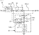
- FIG. 1 is a view of the circuit illustrating a DC breaker according to an embodiment according to the present disclosure.
- the DC breaker includes a mechanical switch 10, a unidirectional power control switching circuit 20, and a current flow control circuit 30.
- a unidirectional power control switching circuit 20 is connected between the second direct current line DCL2 and a ground to be in parallel with the mechanical switch 10 and enables a current to become zero Iz by supplying resonant current Ilc to the mechanical switch 10 where a steady state current Idc enters into when a fault current Ifault at the mechanical switch 10 is generated.
- the unidirectional power control switching circuit 20 when the fault current Ifault is generated, allowing the current of the first direct current line DCL1 to become zero Iz by supplying the resonant current Ilc via second direct current line DCL2 to the first direct current line DCL1 where the steady state current Idc enters, prevents an arc from occurring or facilitates arc-suppressing for the arc generated during an opening operation of the mechanical switch 10 where the steady state current Idc enters.
- the DC breaker having configuration as above, according to the present disclosure is described in more detail as follows.
- the mechanical switch 10 includes a contact point terminal 11 and a switching contact point terminal 12 as illustrated in FIG. 1 .
- the contact point terminal 11 to be located on one end of the mechanical switch 10 is connected to the first direct current line DCL1 and allows the steady state current Idc to flow into the switching contact point terminal 12 in a state that the mechanical switch 10 is closed when the steady state current Idc is supplied through the first direct current line DCL1.
- the switching contact point terminal 12 to be located on an opposite end of the mechanical switch 10 is connected to the second direct current line DCL2 and transfers the steady state current Idc being supplied from the first direct current line DCL1 to the second direct current line DCL2.
- the mechanical switch 10 like this blocks entering of the fault current Ifault which is generated in the second direct current line DCL2 by disconnecting a connected state between the contact point terminal 11 and the switching contact point terminal 12 when the fault current Ifault is generated in the second direct current line DCL2 and the current entering into the first direct current line DCL1 becomes the zero Iz.
- a unidirectional power control switching circuit 20 is configured to include a first unidirectional semiconductor switch device 21, an LC resonant circuit 22, and a second unidirectional semiconductor switch device 23, as illustrated in FIG. 1 .
- the first unidirectional semiconductor switch device 21 is connected to the second direct current line DCL2 to be in parallel with the mechanical switch 10 and allows the entering current to become zero Iz by transferring the resonant current Ilc to the first direct current line DCL1 in the case where the steady state current Idc enters into the first direct current line when the fault current Ifault is generated.
- the first unidirectional semiconductor switch device 21 like this is a semiconductor device capable of performing on/off control to transfer the resonant current Ilc to the first direct current line DCL1 where the steady state current Idc enters into when the fault current Ifault is generated, and, for example, the first thyristor can be used for this.
- the first thyristor THR1 enables the current entering into the first direct current line DCL1 to become zero Iz by transferring the resonant current Ilc to the mechanical switch 10 which is connected to the first direct current line DCL1 where the steady state current Idc enters when the fault current Ifault is generated, and is configured with a cathode terminal K1, an anode terminal A1, and a gate terminal G1.
- the anode terminal A1 of the first thyristor THR1 is connected to the LC resonant circuit 22 and cathode terminal K1 is connected to the second direct current line DCL2.
- the gate terminal G1 is connected to a controller (not shown) and is activated when a trigger pulse is received from the controller due to generation of the fault current Ifault. Then, the gate terminal G1 makes the current to become zero Iz by transferring the resonant current Ilc generated from the LC resonant circuit 22 to the first direct current line DCL1, the transfer occurring at the location where the steady state current Idc enters into the first direct current line.
- the LC resonant circuit 22 is configured with a capacitor C and an inductor L and is connected to the first unidirectional semiconductor switch device 21 in series.
- the LC resonant circuit 22 is charged with the steady state current Idc being received from the first direct current line DCL1 and generates and supplies the resonant current Ilc, i.e., LC resonant current by using charged current when the first unidirectional semiconductor switch device 21 is triggered.
- Ilc i.e., LC resonant current by using charged current when the first unidirectional semiconductor switch device 21 is triggered.
- FIG. 1 an embodiment is illustrated in FIG. 1 in such a way that the capacitor C is charged by receiving the steady state current Idc entering from the first direct current line DCL1, in another embodiment, the capacitor C can be also charged from the right side to the left of FIG.
- the capacitor C is charged with the steady state current Idc being supplied via the first direct current line DCL1 and the inductor L, connected to the capacitor C, generates and supplies the resonant current Ilc when the first unidirectional semiconductor switch device 21 is activated.
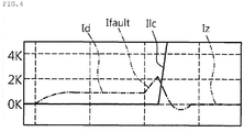
- the resonant current Ilc supplied from the LC resonant circuit 22 having configuration like this is greater than the steady state current Idc entering into the first direct current line DCL1. That is, the resonant current Ilc is a current supplied from the LC resonant circuit 22 when resonance occurs by capacitive reactance and inductive reactance coinciding with each other, and becomes a maximum current as illustrated in FIG. 4 .
- the LC resonant circuit 22 is connected to a ground GND, thereby allowing the steady state current Idc entering into the first direct current line DCL1 to be supplied to the LC resonant circuit 22.
- the second unidirectional semiconductor switch device 23 is connected in parallel with the first unidirectional semiconductor switch device 21 and the LC resonant circuit 22 and allows the capacitor C provided in the LC resonant circuit 22 to be charged by supplying the steady state current Idc to the LC resonant circuit 22.
- the second unidirectional semiconductor switch device 23 like this is arranged in reverse direction of the first unidirectional semiconductor switch device 21 and is connected to both of the one end of mechanical switch 10 and the first direct current line DCL1, as in FIG. 1 , thereby switching the flow of the current.
- a second unidirectional semiconductor switch device 23 is a semiconductor device capable of performing on/off control and, for example, the second thyristor THR2 can be used for this.
- the second thyristor is connected between the first direct current line DCL1 and the anode A1 of the first thyristor THR1 to supply the steady state current Idc from the first direct current line DCL1 to the LC resonant circuit 22. That is, the second thyristor THR2 is connected between the first direct current line DCL1 and an intermediate point N between the first thyristor THR1 and the LC resonant circuit 22, and equipped with a cathode terminal K2, an anode terminal A2, and a gate terminal G2.
- the anode terminal A2 of the second thyristor THR2 is connected to the first direct current line DCL1 and the cathode terminal K2 is connected to the intermediate point N between the anode terminal A1 of the first thyristor THR1 and the LC resonant circuit 22.
- the gate terminal G2 is connected to the controller described above and is activated in response to a trigger pulse output from the controller, thus allowing the steady state current Idc from the first direct current line DCL1 to enter into the LC resonant circuit 22 via the second thyristor THR2.
- the current flow control circuit 30 being connected to the one end or the opposite end of the mechanical switch 10 controls the current flow and is composed of the inductor L and the diode D.
- the inductor L is connected to the one end or the opposite end of the mechanical switch 10 and limits the rate of rise of the fault current Ifault di/dt and the diode D is connected in parallel with the inductor L and limits the limitation function of the current of the inductor L.
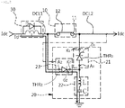
- the DC breaker illustrated in FIG. 1 illustrates a state that the steady state current Idc is supplied from the first direct current line DCL1 to the second direct current line DCL2.
- the contact point terminal 11 and the switching contact point terminal 12 provided in the mechanical switch 10 enter into a state of being connected.
- the steady state current Idc is supplied from the first direct current line DCL1 to the second direct current line DCL2 via the mechanical switch 10.
- the first direct current line DCL1 and the second direct current line DCL2 may use the same lines.
- the steady state current Idc is supplied to the first direct current line DCL1
- the steady state current Idc flows into the LC resonant circuit 22 by the second unidirectional semiconductor switch device 23 being in an On state and allows the capacitor C of the LC resonant circuit 22 to be charged.
- the first thyristor THR1 used as the first unidirectional semiconductor switch device 21 is turned on by activating by the trigger signal output from the controller.
- the resonant current Ilc is generated in the LC resonant circuit 22 by the voltage charged in the capacitor C, and the generated resonant current Ilc enters into the first direct current line DCL1, thereby enabling the current entering into the first direct current line DCL1 to become zero Iz.
- the resonant current Ilc like this is transferred to the first direct current line DCL1 through the second direct current line DCL2 connected to the opposite end of the mechanical switch 10 and the mechanical switch 10.
- the fault current Ifault is prevented from entering into the first direct current line DCL1 by opening the mechanical switch 10 connected to the first direct current line DCL1.
- the fault current Ifault can be prevented from entering into the first direct current line DCL1 without generating an arc through disconnecting the connected state of the contact point terminal 11 and the switching contact point terminal 12. That is, as in FIG.
- a vertical axis represents an amount of current ampere and horizontal axis a time.
- the steady state current Idc After the fault current Ifault is blocked, when the steady state current Idc enters into the second direct current line DCL2 where the fault current Ifault was generated, as alternating long and two short dashes line illustrated in FIG. 1 , the steady state current Idc charges the capacitor C of the LC resonant circuit 21 and generates the resonant current Ilc when the next fault current Ifault is generated.
- the first direct current line DCL1 can be managed safely and reliably.
- the DC breaker according to the present disclosure can block the fault current generated in the direct current line by using the unidirectional semiconductor switch and can improve operating reliability of the product by simplifying the structure of the DC breaker and by blocking the fault current by using only a single unidirectional semiconductor switch, thereby saving the manufacturing cost.
Landscapes
- Engineering & Computer Science (AREA)
- Power Engineering (AREA)
- Driving Mechanisms And Operating Circuits Of Arc-Extinguishing High-Tension Switches (AREA)
- Keying Circuit Devices (AREA)
Applications Claiming Priority (2)
| Application Number | Priority Date | Filing Date | Title |
|---|---|---|---|
| KR1020150088177A KR101688921B1 (ko) | 2015-06-22 | 2015-06-22 | Dc 차단기 |
| PCT/KR2016/006632 WO2016208968A1 (fr) | 2015-06-22 | 2016-06-22 | Disjoncteur de courant continu |
Publications (2)
| Publication Number | Publication Date |
|---|---|
| EP3312866A1 true EP3312866A1 (fr) | 2018-04-25 |
| EP3312866A4 EP3312866A4 (fr) | 2019-01-23 |
Family
ID=57585744
Family Applications (1)
| Application Number | Title | Priority Date | Filing Date |
|---|---|---|---|
| EP16814681.9A Withdrawn EP3312866A4 (fr) | 2015-06-22 | 2016-06-22 | Disjoncteur de courant continu |
Country Status (4)
| Country | Link |
|---|---|
| US (1) | US10672574B2 (fr) |
| EP (1) | EP3312866A4 (fr) |
| KR (1) | KR101688921B1 (fr) |
| WO (1) | WO2016208968A1 (fr) |
Families Citing this family (16)
| Publication number | Priority date | Publication date | Assignee | Title |
|---|---|---|---|---|
| KR101550374B1 (ko) * | 2013-12-31 | 2015-09-04 | 주식회사 효성 | 고전압 dc 차단기 |
| JP6741211B2 (ja) * | 2016-08-05 | 2020-08-19 | 株式会社Gsユアサ | 蓄電装置、車両、及び蓄電装置の充電制御方法 |
| CN107069653B (zh) * | 2017-05-17 | 2019-03-01 | 中国科学院电工研究所 | 一种直流限流开断装置 |
| WO2018229970A1 (fr) * | 2017-06-16 | 2018-12-20 | 東芝エネルギーシステムズ株式会社 | Disjoncteur à courant continu, dispositif interrupteur mécanique pour disjoncteur à courant continu et dispositif interrupteur à semi-conducteurs pour disjoncteur à courant continu |
| CN109003851B (zh) * | 2017-07-24 | 2020-01-14 | 广州市金矢电子有限公司 | 直流灭弧电路及装置 |
| CN108962647B (zh) * | 2017-07-24 | 2021-08-27 | 广州市金矢电子有限公司 | 直流灭弧装置 |
| WO2020101741A1 (fr) * | 2018-11-13 | 2020-05-22 | Illinois Institute Of Technology | Disjoncteur hybride utilisant un circuit d'injection de courant de commutation transitoire |
| WO2020114410A1 (fr) * | 2018-12-08 | 2020-06-11 | 郭桥石 | Appareil suppresseur de tension transitoire |
| CN109888743A (zh) * | 2019-02-28 | 2019-06-14 | 华北电力大学 | 一种适用于直流电网的降压钳位式直流断路器 |
| KR102234244B1 (ko) * | 2019-08-23 | 2021-04-01 | 주식회사 디케이 | Dc 차단기 |
| KR102274612B1 (ko) * | 2019-09-18 | 2021-07-07 | 엘지전자 주식회사 | 아크 소호 기능을 갖는 차단기 및 이를 이용한 보호 계전 시스템 |
| CN110830324B (zh) * | 2019-10-28 | 2021-09-03 | 烽火通信科技股份有限公司 | 一种检测数据中心网络连通性的方法、装置及电子设备 |
| WO2021115101A1 (fr) * | 2019-12-13 | 2021-06-17 | 浙江大维高新技术股份有限公司 | Disjoncteur à courant continu bidirectionnel entièrement solide à tension moyenne-élevée et appareil d'alimentation en énergie à potentiel élevé associé |
| EP3920352A1 (fr) | 2020-06-05 | 2021-12-08 | Hamilton Sundstrand Corporation | Disjoncteur à courant continu (cc) |
| KR102505689B1 (ko) * | 2020-11-25 | 2023-03-02 | 아주대학교산학협력단 | 반도체 소자와 lc 공진 회로를 이용한 하이브리드 dc 차단기 |
| CN114156846B (zh) * | 2021-12-02 | 2022-07-08 | 中国科学院电工研究所 | 低损耗多端直流断路器及其控制方法 |
Family Cites Families (19)
| Publication number | Priority date | Publication date | Assignee | Title |
|---|---|---|---|---|
| US4805062A (en) * | 1986-10-15 | 1989-02-14 | Hitachi, Ltd. | DC circuit breaker and method of commutation thereof |
| ATE89685T1 (de) * | 1986-12-22 | 1993-06-15 | Acec Transport Sa | Durch halbleiter unterstuetzter ultra-schneller schalter. |
| JP3355066B2 (ja) * | 1995-06-28 | 2002-12-09 | 三菱電機株式会社 | 両方向直流遮断器 |
| JP2000090787A (ja) | 1998-09-17 | 2000-03-31 | Mitsubishi Electric Corp | 遮断装置およびそれを応用した直流送電システム |
| KR100344056B1 (ko) * | 1999-03-17 | 2002-07-22 | 주식회사 포스콘 | 직류 대전류 차단장치 |
| JP3943817B2 (ja) * | 2000-09-18 | 2007-07-11 | 株式会社東芝 | 真空直流遮断器 |
| JP3965037B2 (ja) * | 2001-10-12 | 2007-08-22 | 東芝三菱電機産業システム株式会社 | 直流用真空遮断装置 |
| KR100434153B1 (ko) * | 2002-04-12 | 2004-06-04 | 엘지산전 주식회사 | 하이브리드 직류 전자 접촉기 |
| EP2289085B1 (fr) | 2008-06-10 | 2014-05-07 | ABB Technology AG | Sectionneur à courant continu |
| JP5214066B1 (ja) * | 2012-05-01 | 2013-06-19 | 三菱電機株式会社 | 直流遮断器 |
| KR101483084B1 (ko) | 2013-01-24 | 2015-01-16 | 한국전기연구원 | 직류 전류 차단 장치 및 방법 |
| KR101506581B1 (ko) * | 2013-08-14 | 2015-03-27 | 주식회사 효성 | 고전압 dc 차단기 |
| KR101522412B1 (ko) * | 2013-12-26 | 2015-05-26 | 주식회사 효성 | 양방향 직류 차단장치 |
| KR101522411B1 (ko) | 2013-12-26 | 2015-05-21 | 주식회사 효성 | 단일회로로 양방향 고장전류를 차단하는 dc차단기 |
| KR20150078491A (ko) * | 2013-12-30 | 2015-07-08 | 주식회사 효성 | 고전압 dc 차단기 |
| KR101679722B1 (ko) * | 2013-12-31 | 2016-11-25 | 주식회사 효성 | Dc 차단기 |
| KR101550374B1 (ko) * | 2013-12-31 | 2015-09-04 | 주식회사 효성 | 고전압 dc 차단기 |
| KR101697623B1 (ko) * | 2014-12-29 | 2017-01-18 | 주식회사 효성 | Dc 차단기 |
| KR101845826B1 (ko) * | 2016-11-21 | 2018-04-09 | 전남대학교산학협력단 | 신뢰성 향상의 양방향 dc 차단기 |
-
2015
- 2015-06-22 KR KR1020150088177A patent/KR101688921B1/ko active Active
-
2016
- 2016-06-22 EP EP16814681.9A patent/EP3312866A4/fr not_active Withdrawn
- 2016-06-22 WO PCT/KR2016/006632 patent/WO2016208968A1/fr not_active Ceased
- 2016-06-22 US US15/738,806 patent/US10672574B2/en active Active
Also Published As
| Publication number | Publication date |
|---|---|
| EP3312866A4 (fr) | 2019-01-23 |
| WO2016208968A1 (fr) | 2016-12-29 |
| US10672574B2 (en) | 2020-06-02 |
| US20180174784A1 (en) | 2018-06-21 |
| KR101688921B1 (ko) | 2017-01-02 |
Similar Documents
| Publication | Publication Date | Title |
|---|---|---|
| US10672574B2 (en) | DC breaker capable of blocking fault current generated in direct current lines | |
| EP3091626B1 (fr) | Disjoncteur à courant continu haute tension | |
| EP3242310B1 (fr) | Coupe-circuit c.c. | |
| US10176939B2 (en) | High-voltage DC circuit breaker for blocking current flowing through DC lines | |
| KR101679722B1 (ko) | Dc 차단기 | |
| EP3035471B1 (fr) | Disjoncteur à cc à haute tension | |
| EP3089301A1 (fr) | Disjoncteur continu bidirectionnel | |
| US8830649B2 (en) | Free-wheeling circuit | |
| JP6042035B2 (ja) | 直流遮断装置 | |
| EP3242309B1 (fr) | Disjoncteur à courant continu à haute tension | |
| EP3242367B1 (fr) | Disjoncteur de circuit à courant continu cc | |
| CN111937110B (zh) | 开关设备 | |
| US20190027327A1 (en) | Direct current circuit breaker | |
| US20180122612A1 (en) | Interrupter device for interrupting a direct current | |
| US20210336435A1 (en) | T-type dc circuit breaker and method for controlling the same | |
| WO2017020269A1 (fr) | Soupape de puissance bidirectionnelle et son procédé de commande et système ccht à terminaux multiples hybride l'utilisant | |
| EP3309809A1 (fr) | Appareil d'interruption de courant continu, procédé d'interruption de courant continu | |
| JP2016024978A (ja) | 開閉器 | |
| KR102615108B1 (ko) | 진공 갭 스위치를 이용한 역전류 주입형 직류 전류 차단 장치 및 방법 | |
| JP6399848B2 (ja) | 開閉器 | |
| WO2016199407A1 (fr) | Appareil d'interruption de courant continu, procédé d'interruption de courant continu |
Legal Events
| Date | Code | Title | Description |
|---|---|---|---|
| PUAI | Public reference made under article 153(3) epc to a published international application that has entered the european phase |
Free format text: ORIGINAL CODE: 0009012 |
|
| 17P | Request for examination filed |
Effective date: 20171220 |
|
| AK | Designated contracting states |
Kind code of ref document: A1 Designated state(s): AL AT BE BG CH CY CZ DE DK EE ES FI FR GB GR HR HU IE IS IT LI LT LU LV MC MK MT NL NO PL PT RO RS SE SI SK SM TR |
|
| AX | Request for extension of the european patent |
Extension state: BA ME |
|
| DAV | Request for validation of the european patent (deleted) | ||
| DAX | Request for extension of the european patent (deleted) | ||
| A4 | Supplementary search report drawn up and despatched |
Effective date: 20190102 |
|
| RAP1 | Party data changed (applicant data changed or rights of an application transferred) |
Owner name: HYOSUNG HEAVY INDUSTRIES CORPORATION |
|
| RIC1 | Information provided on ipc code assigned before grant |
Ipc: H01H 33/14 20060101ALI20181218BHEP Ipc: H01H 33/59 20060101AFI20181218BHEP Ipc: H01H 33/02 20060101ALI20181218BHEP |
|
| STAA | Information on the status of an ep patent application or granted ep patent |
Free format text: STATUS: THE APPLICATION IS DEEMED TO BE WITHDRAWN |
|
| 18D | Application deemed to be withdrawn |
Effective date: 20190730 |