EP3312921B1 - Pile, empilement de piles à combustible, système de pile à combustible et corps assemblé par un ensemble membrane-électrode - Google Patents
Pile, empilement de piles à combustible, système de pile à combustible et corps assemblé par un ensemble membrane-électrode Download PDFInfo
- Publication number
- EP3312921B1 EP3312921B1 EP16811160.7A EP16811160A EP3312921B1 EP 3312921 B1 EP3312921 B1 EP 3312921B1 EP 16811160 A EP16811160 A EP 16811160A EP 3312921 B1 EP3312921 B1 EP 3312921B1
- Authority
- EP
- European Patent Office
- Prior art keywords
- cell
- catalyst layer
- electrically conductive
- conductive material
- electrical resistance
- Prior art date
- Legal status (The legal status is an assumption and is not a legal conclusion. Google has not performed a legal analysis and makes no representation as to the accuracy of the status listed.)
- Active
Links
Images





Classifications
-
- H—ELECTRICITY
- H01—ELECTRIC ELEMENTS
- H01M—PROCESSES OR MEANS, e.g. BATTERIES, FOR THE DIRECT CONVERSION OF CHEMICAL ENERGY INTO ELECTRICAL ENERGY
- H01M4/00—Electrodes
- H01M4/86—Inert electrodes with catalytic activity, e.g. for fuel cells
- H01M4/90—Selection of catalytic material
- H01M4/92—Metals of platinum group
-
- H—ELECTRICITY
- H01—ELECTRIC ELEMENTS
- H01M—PROCESSES OR MEANS, e.g. BATTERIES, FOR THE DIRECT CONVERSION OF CHEMICAL ENERGY INTO ELECTRICAL ENERGY
- H01M4/00—Electrodes
- H01M4/86—Inert electrodes with catalytic activity, e.g. for fuel cells
- H01M4/8663—Selection of inactive substances as ingredients for catalytic active masses, e.g. binders, fillers
- H01M4/8673—Electrically conductive fillers
-
- B—PERFORMING OPERATIONS; TRANSPORTING
- B01—PHYSICAL OR CHEMICAL PROCESSES OR APPARATUS IN GENERAL
- B01J—CHEMICAL OR PHYSICAL PROCESSES, e.g. CATALYSIS OR COLLOID CHEMISTRY; THEIR RELEVANT APPARATUS
- B01J23/00—Catalysts comprising metals or metal oxides or hydroxides, not provided for in group B01J21/00
- B01J23/38—Catalysts comprising metals or metal oxides or hydroxides, not provided for in group B01J21/00 of noble metals
- B01J23/40—Catalysts comprising metals or metal oxides or hydroxides, not provided for in group B01J21/00 of noble metals of the platinum group metals
- B01J23/42—Platinum
-
- B—PERFORMING OPERATIONS; TRANSPORTING
- B01—PHYSICAL OR CHEMICAL PROCESSES OR APPARATUS IN GENERAL
- B01J—CHEMICAL OR PHYSICAL PROCESSES, e.g. CATALYSIS OR COLLOID CHEMISTRY; THEIR RELEVANT APPARATUS
- B01J23/00—Catalysts comprising metals or metal oxides or hydroxides, not provided for in group B01J21/00
- B01J23/38—Catalysts comprising metals or metal oxides or hydroxides, not provided for in group B01J21/00 of noble metals
- B01J23/54—Catalysts comprising metals or metal oxides or hydroxides, not provided for in group B01J21/00 of noble metals combined with metals, oxides or hydroxides provided for in groups B01J23/02 - B01J23/36
- B01J23/56—Platinum group metals
- B01J23/64—Platinum group metals with arsenic, antimony, bismuth, vanadium, niobium, tantalum, polonium, chromium, molybdenum, tungsten, manganese, technetium or rhenium
- B01J23/648—Vanadium, niobium or tantalum or polonium
-
- H—ELECTRICITY
- H01—ELECTRIC ELEMENTS
- H01M—PROCESSES OR MEANS, e.g. BATTERIES, FOR THE DIRECT CONVERSION OF CHEMICAL ENERGY INTO ELECTRICAL ENERGY
- H01M4/00—Electrodes
- H01M4/86—Inert electrodes with catalytic activity, e.g. for fuel cells
-
- H—ELECTRICITY
- H01—ELECTRIC ELEMENTS
- H01M—PROCESSES OR MEANS, e.g. BATTERIES, FOR THE DIRECT CONVERSION OF CHEMICAL ENERGY INTO ELECTRICAL ENERGY
- H01M4/00—Electrodes
- H01M4/86—Inert electrodes with catalytic activity, e.g. for fuel cells
- H01M4/8647—Inert electrodes with catalytic activity, e.g. for fuel cells consisting of more than one material, e.g. consisting of composites
- H01M4/8657—Inert electrodes with catalytic activity, e.g. for fuel cells consisting of more than one material, e.g. consisting of composites layered
-
- H—ELECTRICITY
- H01—ELECTRIC ELEMENTS
- H01M—PROCESSES OR MEANS, e.g. BATTERIES, FOR THE DIRECT CONVERSION OF CHEMICAL ENERGY INTO ELECTRICAL ENERGY
- H01M4/00—Electrodes
- H01M4/86—Inert electrodes with catalytic activity, e.g. for fuel cells
- H01M4/90—Selection of catalytic material
-
- H—ELECTRICITY
- H01—ELECTRIC ELEMENTS
- H01M—PROCESSES OR MEANS, e.g. BATTERIES, FOR THE DIRECT CONVERSION OF CHEMICAL ENERGY INTO ELECTRICAL ENERGY
- H01M8/00—Fuel cells; Manufacture thereof
- H01M8/02—Details
-
- H—ELECTRICITY
- H01—ELECTRIC ELEMENTS
- H01M—PROCESSES OR MEANS, e.g. BATTERIES, FOR THE DIRECT CONVERSION OF CHEMICAL ENERGY INTO ELECTRICAL ENERGY
- H01M8/00—Fuel cells; Manufacture thereof
- H01M8/02—Details
- H01M8/0202—Collectors; Separators, e.g. bipolar separators; Interconnectors
- H01M8/0204—Non-porous and characterised by the material
- H01M8/0206—Metals or alloys
-
- H—ELECTRICITY
- H01—ELECTRIC ELEMENTS
- H01M—PROCESSES OR MEANS, e.g. BATTERIES, FOR THE DIRECT CONVERSION OF CHEMICAL ENERGY INTO ELECTRICAL ENERGY
- H01M8/00—Fuel cells; Manufacture thereof
- H01M8/10—Fuel cells with solid electrolytes
-
- H—ELECTRICITY
- H01—ELECTRIC ELEMENTS
- H01M—PROCESSES OR MEANS, e.g. BATTERIES, FOR THE DIRECT CONVERSION OF CHEMICAL ENERGY INTO ELECTRICAL ENERGY
- H01M8/00—Fuel cells; Manufacture thereof
- H01M8/10—Fuel cells with solid electrolytes
- H01M8/1004—Fuel cells with solid electrolytes characterised by membrane-electrode assemblies [MEA]
-
- H—ELECTRICITY
- H01—ELECTRIC ELEMENTS
- H01M—PROCESSES OR MEANS, e.g. BATTERIES, FOR THE DIRECT CONVERSION OF CHEMICAL ENERGY INTO ELECTRICAL ENERGY
- H01M8/00—Fuel cells; Manufacture thereof
- H01M8/10—Fuel cells with solid electrolytes
- H01M8/1016—Fuel cells with solid electrolytes characterised by the electrolyte material
- H01M8/1018—Polymeric electrolyte materials
-
- H—ELECTRICITY
- H01—ELECTRIC ELEMENTS
- H01M—PROCESSES OR MEANS, e.g. BATTERIES, FOR THE DIRECT CONVERSION OF CHEMICAL ENERGY INTO ELECTRICAL ENERGY
- H01M4/00—Electrodes
- H01M4/86—Inert electrodes with catalytic activity, e.g. for fuel cells
- H01M2004/8678—Inert electrodes with catalytic activity, e.g. for fuel cells characterised by the polarity
- H01M2004/8684—Negative electrodes
-
- H—ELECTRICITY
- H01—ELECTRIC ELEMENTS
- H01M—PROCESSES OR MEANS, e.g. BATTERIES, FOR THE DIRECT CONVERSION OF CHEMICAL ENERGY INTO ELECTRICAL ENERGY
- H01M8/00—Fuel cells; Manufacture thereof
- H01M8/10—Fuel cells with solid electrolytes
- H01M2008/1095—Fuel cells with polymeric electrolytes
-
- Y—GENERAL TAGGING OF NEW TECHNOLOGICAL DEVELOPMENTS; GENERAL TAGGING OF CROSS-SECTIONAL TECHNOLOGIES SPANNING OVER SEVERAL SECTIONS OF THE IPC; TECHNICAL SUBJECTS COVERED BY FORMER USPC CROSS-REFERENCE ART COLLECTIONS [XRACs] AND DIGESTS
- Y02—TECHNOLOGIES OR APPLICATIONS FOR MITIGATION OR ADAPTATION AGAINST CLIMATE CHANGE
- Y02E—REDUCTION OF GREENHOUSE GAS [GHG] EMISSIONS, RELATED TO ENERGY GENERATION, TRANSMISSION OR DISTRIBUTION
- Y02E60/00—Enabling technologies; Technologies with a potential or indirect contribution to GHG emissions mitigation
- Y02E60/30—Hydrogen technology
- Y02E60/50—Fuel cells
Definitions
- the present invention relates to a cell, a fuel cell stack, a fuel cell system, and a membrane electrode assembly.
- the fuel gas remaining in a fuel gas channel may leak from the fuel gas channel, or may pass through a polymer electrolyte membrane. In such a case, air enters the fuel gas channel in place of the fuel gas. If the fuel cell is re-started in such a state, an oxygen reduction reaction occurs at the anode. This causes degradation of a catalyst used for the cathode. In order to avoid such catalyst degradation, at the time of re-starting the fuel cell, air remaining in the fuel gas channel is purged from the fuel gas channel by using an inert gas before the fuel gas is supplied to the fuel gas channel.
- JP 2006 019133 A relates to an anode electrode for a fuel cell.
- JP 3 236686 B2 relates to a gas electrode.
- US 2009/312181 A1 relates to method of synthesizing a mesoporous catalyst support material comprising TiO2.
- An object of the present invention is to provide a fuel cell system capable of suppressing deterioration in power generation performance while suppressing increase in its size and cost.
- a cell according to the present invention is defined in claim 1.
- a fuel cell stack and a fuel cell system are defined in claims 10 and 11 respectively.
- a membrane electrode assembly is defined in claim 12. Further advantageous embodiments are defined in the dependent claims.
- the present invention exerts, in a cell, a fuel cell stack, a fuel cell system, and a membrane electrode assembly, an advantageous effect of being able to suppress deterioration in power generation performance while suppressing increase in their size and cost.
- the inventors of the present invention conducted diligent studies on a cell, a fuel cell stack, a fuel cell system, and a membrane electrode assembly from the viewpoint of suppressing deterioration in power generation performance while suppressing increase in their size and cost. As a result of the studies, the inventors of the present invention have found the following problems in the conventional art.
- a cathode carbon corrosion reaction occurs in the downstream part of the fuel gas channel, in which part the air remains.
- an oxygen reduction reaction of 2H + + 1/2O 2 + 2e - ⁇ H 2 O occurs at the anode, and a reaction of 1/2C + H 2 O ⁇ 1/2CO 2 + 2H + + 2e - occurs at the cathode.
- the cathode catalyst layer degrades, which causes deterioration in the power generation performance of the fuel cell.
- each of the fuel cells disclosed in Patent Literatures 1 and 2 suppresses the corrosion reaction by lowering the oxygen reduction capability of the anode catalyst layer.
- hydrogen oxidation capability which is the originally intended function of the anode catalyst layer, is also lowered, which consequently impairs the power generation performance of the fuel cell.
- the inventors of the present invention conducted the diligent studies, and as a result of the studies, they have found that the deterioration in the power generation performance of the fuel cell can be suppressed by setting the electrical resistance of the anode under an oxygen atmosphere to be higher than the electrical resistance of the anode under a hydrogen atmosphere. Based on the findings, the inventors have conceived of the present invention.
- a cell according to the present invention is defined in claim 1.
- a cell according to a second aspect of the present invention is configured such that, in the above first aspect, the anode catalyst layer contains an ion-conductive binder.
- a cell according to a third aspect of the present invention is configured such that, in the above first or second aspect, the second electrically conductive material is carbon.
- a cell according to a fourth aspect of the present invention is configured such that, in any one of the above first to third aspects, the first electrically conductive material is formed as particles, and an average primary diameter of the particles is not smaller than 10 nm and not greater than 1000 nm.
- a cell according to a fifth aspect of the present invention is configured such that, in any one of the above first to fourth aspects, the first catalyst material contains platinum or a platinum alloy.
- a cell according to a sixth aspect of the present invention is configured such that, in any one of the above first to fifth aspects, the first catalyst material is formed as particles, and an average primary diameter of the particles is not smaller than 1 nm and not greater than 10 nm.
- a cell according to a seventh aspect of the present invention is configured such that, in any one of the above first to sixth aspects, the electrical resistance of the cell when the anode catalyst layer is under an oxygen atmosphere is nine times or more as high as the electrical resistance of the cell when the anode catalyst layer is under a hydrogen atmosphere.
- a cell according to an eighth and ninth aspect of the invention is defined in claims 8 and 9.
- a fuel cell stack according to a tenth aspect of the present invention includes a plurality of the cells according to any one of the above first to ninth aspects, the cells being stacked together.
- a fuel cell system includes: a fuel cell stack including a plurality of the cells according to any one of claims 1 to 9, the cells being stacked together; a fuel gas supply device configured to supply a fuel gas to one channel of the pair of separators; and an oxidant gas supply device configured to supply an oxidant gas to another channel of the pair of separators.
- a membrane electrode assembly according to the present invention is defined in claim 12.
- Fig. 1 is a functional block diagram schematically showing the configuration of the fuel cell system 100.
- the fuel cell system 100 includes a fuel cell stack 10, a fuel gas supply device 30, and an oxidant gas supply device 50.
- the fuel cell stack 10 is a reactor configured to generate electric power by causing a hydrogen-containing fuel gas and an oxidant gas to electrochemically react with each other (hereinafter, such a reaction is referred to as a power-generating reaction).
- the fuel cell stack 10 includes a plurality of cells 11 that are stacked together.
- the fuel gas supply device 30 is a device configured to supply the fuel gas to a channel of the fuel cell stack 10.
- the fuel gas supply device 30 is connected to the channel of the fuel cell stack 10 by a first passage 31, and the fuel gas is supplied to the fuel cell stack 10 through the first passage 31.
- the fuel gas supply device 30 has a function of adjusting the flow rate of the fuel gas, and the adjustment is performed by a controller (not shown).
- the fuel gas is a hydrogen-containing gas.
- Examples of the fuel gas supply device 30 include a reformer, a hydrogen cylinder, and a hydrogen gas infrastructure.
- the reformer is a reactor configured to generate the fuel gas from a raw material gas by a suitable method, such as a steam reforming method, a partial oxidation method, or an autothermal method.
- the oxidant gas supply device 50 is a device configured to supply the oxidant gas to a channel of the fuel cell stack 10.
- the oxidant gas supply device 50 is connected to the channel of the fuel cell stack 10 by a second passage 51, and the oxidant gas is supplied to the fuel cell stack 10 through the second passage 51.
- the oxidant gas supply device 50 has a function of adjusting the feeding flow rate of the oxidant gas. This adjustment is performed by a controller (not shown).
- Examples of the oxidant gas include air and oxygen.
- Examples of the oxidant gas supply device 50 include an air blowing machine that feeds air, such as a fan or a blower, and an oxygen cylinder.
- Fig. 2 is a sectional view schematically showing a part of the fuel cell stack 10.
- the fuel cell stack 10 is a stack of polymer electrolyte fuel cells, and generates electric power by causing an oxidation-reduction reaction between the fuel gas and the oxidant gas (this oxidation-reduction reaction is hereinafter referred to as a power-generating reaction).
- the fuel gas is a hydrogen-containing gas.
- air containing oxygen is used as the oxidant gas.
- the fuel cell stack 10 includes the plurality of cells 11 that are stacked together.
- Each cell 11 is a cell having a resistance-changing property, i.e., the electrical resistance thereof changes depending on a gas type (between oxygen and hydrogen).
- the resistance-changing property herein means that the electrical resistance of the cell 11 when an anode 16 is under a hydrogen atmosphere, such as when the anode 16 is being exposed to, for example, the fuel gas, is different from the electrical resistance of the cell 11 when the anode 16 is under an oxygen atmosphere, such as when the anode 16 is being exposed to, for example, air containing oxygen.
- the cell 11 includes: a membrane electrode assembly (MEA) 12; and a pair of plate-shaped separators 13 and 14, between which the MEA 12 is interposed.
- the MEA 12 includes a polymer electrolyte membrane 15, the anode 16, and a cathode 17.
- the polymer electrolyte membrane 15 is made of a material that exhibits high electrical conductivity in wet conditions.
- a proton (ion)-conductive ion-exchange membrane made of a fluorine-based resin is used as the polymer electrolyte membrane 15.
- the polymer electrolyte membrane 15 includes a first main surface and a second main surface. The second main surface is positioned at the opposite side to the first main surface.
- each of the first main surface and the second main surface is rectangular, and the area of each of the first main surface and the second main surface is larger than the area of each of the other surfaces, i.e., the surfaces other than the first and second main surfaces, of the polymer electrolyte membrane 15.
- Each of the anode 16 and the cathode 17 is an electrode that includes an electrically conductive catalyst support with a catalyst supported thereon.
- the anode 16 includes a gas diffusion layer 18 and a catalyst layer (anode catalyst layer) 19.
- the cathode 17 includes a gas diffusion layer 18 and a catalyst layer (cathode catalyst layer) 20.
- Each gas diffusion layer 18 has a current collecting function, gas permeability, and water repellency, and includes a base 21 and a coating layer 22.
- the base 21 has a porous structure, and is made of an electrically conductive material having high gas and liquid permeability, for example, a carbonaceous material.
- the carbonaceous material is, for example, a carbon fibrous material, such as carbon paper, carbon fiber cloth, or carbon fiber felt.
- One coating layer 22 is interposed between the base 21 and the catalyst layer 19, and the other coating layer 22 is interposed between the base 21 and the catalyst layer 20.
- These coating layers 22 serve to reduce contact resistance between the base 21 and the catalyst layer 19 and between the base 21 and the catalyst layer 20, and improve liquid permeability (drainability).
- each coating layer 22 is made of carbon black and a water repellent.
- the anode catalyst layer 19 has a resistance-changing property, i.e., the electrical resistance thereof changes depending on oxygen and hydrogen. That is, the electrical resistance of the cell 11 when the anode catalyst layer 19 is under an oxygen atmosphere is higher than the electrical resistance of the cell 11 when the anode catalyst layer 19 is under a hydrogen atmosphere. For example, the electrical resistance of the cell 11 when the anode catalyst layer 19 is under an oxygen atmosphere is more than twice the electrical resistance of the cell 11 when the anode catalyst layer 19 is under a hydrogen atmosphere.
- the electrical resistance ratio of the anode catalyst layer 19 is higher than the electrical resistance ratio of the cathode catalyst layer 20.
- the electrical resistance ratio of the anode catalyst layer 19 is the ratio of the electrical resistance of the anode catalyst layer 19 under an oxygen atmosphere to the electrical resistance of the anode catalyst layer 19 under a hydrogen atmosphere.
- the electrical resistance ratio of the cathode catalyst layer 20 is the ratio of the electrical resistance of the cathode catalyst layer 20 under an oxygen atmosphere to the electrical resistance of the cathode catalyst layer 20 under a hydrogen atmosphere.
- the anode catalyst layer 19 is provided on the first main surface of the polymer electrolyte membrane 15.
- the anode catalyst layer 19 contains an ion-conductive binder, a first catalyst material, and a first electrically conductive material.
- the first electrically conductive material has a resistance-changing property, and is, for example, an electrically conductive ceramic having a resistance-changing property.
- a metal oxide is used as the electrically conductive ceramic having a resistance-changing property.
- the metal oxide includes titanium oxide. Examples, not according to the invention, for the metal oxide include tin oxide, and indium oxide. Among these, an electrically conductive ceramic containing titanium is preferable from the viewpoint of chemical/electrochemical stability.
- the average primary diameter of the primary particles of the first electrically conductive material is, for example, not smaller than 10 nm and not greater than 1000 nm. If the particle diameter of the first electrically conductive material is smaller than 10 nm, contact resistance tends to occur between the particles, causing increase in the electrical resistance of the anode catalyst layer 19 under a hydrogen atmosphere. On the other hand, if the particle diameter of the first electrically conductive material is greater than 1000 nm, the electrical resistance of the anode catalyst layer 19 under an oxygen atmosphere is less likely to become high, and thus the resistance-changing property is reduced.
- the electrical resistance of the anode catalyst layer 19 can be made low under a hydrogen atmosphere and high under an oxygen atmosphere, and thus the resistance-changing property of the anode catalyst layer 19 can be exerted.
- the shape of the primary particles of the first electrically conductive material is not particularly limited, so long as the shape allows the specific surface area of the catalyst support to be large.
- Various shapes are adoptable as the shape of the primary particles, such as a spherical shape, a polyhedral shape, a plate shape, a spindle shape, and a combination of these shapes. Among these, a spherical shape is preferable.
- the primary particles of the first electrically conductive material are fusion-bonded to each other to form a chain structure and/or a cluster structure.
- the specific surface area of the catalyst support, contact resistance reduction, and conduction path formation it is preferable that 80% or more of the fused bodies of the primary particles be formed by fusion bonding of five or more primary particles together.
- the specific surface area of the catalyst support made of the first electrically conductive material is, for example, not smaller than 1 m 2 /g and not larger than 100 m 2 /g. In consideration of reducing the particle diameter of the first catalyst material for effective catalyst utilization, it is more preferable that the specific surface area be not smaller than 10 m 2 /g and not larger than 100 m 2 /g. It should be noted that, in general, the specific surface area can be measured by using physical adsorption of, for example, nitrogen gas.
- the electrically conductive ceramic may be doped with a dissimilar metal (a dopant).
- a dopant include niobium, tantalum, antimony, chromium, molybdenum, and tungsten.
- the dopant content in the electrically conductive ceramic is, for example, not less than 0.1 mol% and not more than 40 mol%.
- the electrical conductivity of the first electrically conductive material can be kept high when the dopant content is within this range.
- the dopant content be not less than 0.5 mol% and not more than 30 mol%.
- the dopant content can be calculated by: analyzing a solution in which the anode catalyst layer 19 is dissolved by inductively coupled plasma atomic emission spectrometry or X-ray fluorescence (XRF) analysis; and measuring the concentration of the electrically conductive ceramic and the concentration of the dopant.
- XRF X-ray fluorescence
- the first catalyst material is a material having an activity against a hydrogen oxidation reaction in the power-generating reaction.
- a noble metal and/or an alloy thereof is/are used as the first catalyst material.
- the noble metal include platinum (Pt), ruthenium (Ru), palladium (Pd), iridium (Ir), silver (Ag), and gold (Au).
- platinum and its alloys are preferable.
- platinum and platinum alloys have an activity against the hydrogen oxidation reaction, and also, serve to increase the responsiveness of the change in electrical resistance.
- the first catalyst material is formed as particles, and for example, the average primary diameter of the particles is preferably not smaller than 1 nm and not greater than 20 nm, and more preferably, not smaller than 1 nm and not greater than 10 nm.
- the first catalyst material is supported on the surface of the first electrically conductive material.
- Various methods are adoptable to make the first catalyst material supported on the surface of the first electrically conductive material. For example, a reductant is added to a liquid containing a colloidal precursor containing the first catalyst material, and thereby the precursor is reduced and a colloid containing the first catalyst material is formed. The first electrically conductive material is dispersed in the colloidal solution thus obtained, and thereby the first catalyst material is adsorbed to the surface of the first electrically conductive material. Thereafter, the first electrically conductive material with the first catalyst material adsorbed thereto is removed from the solution and dried, and subjected to heat treatment under a reductive atmosphere.
- the first catalyst material can be made supported on the surface of the first electrically conductive material.
- the heat treatment temperature at the time is, for example, not lower than 150°C and not higher than 1500°C.
- the reason why the heat treatment temperature is preferably not lower than 150°C is that under such conditions, impurities adhered to the surface of the first catalyst material are removed effectively, and a high catalytic activity can be obtained.
- the reason why the heat treatment temperature is preferably not higher than 1500°C is that under such conditions, aggregation of the first catalyst material is suppressed, and a large surface area can be obtained.
- the heat treatment temperature is not lower than 800°C and not higher than 1500°C. The reason why the heat treatment temperature is preferably not lower than 800°C is that under such conditions, the first catalyst material and the first electrically conductive material are partly alloyed, and thereby electron conductivity between the first catalyst material and the first electrically conductive material is improved.
- the cathode catalyst layer 20 is provided on the second main surface of the polymer electrolyte membrane 15.
- the cathode catalyst layer 20 contains a second catalyst material and a second electrically conductive material.
- the second catalyst material is a catalyst having an activity against an oxygen reduction reaction.
- platinum or a platinum alloy is used as the second catalyst material.
- the second electrically conductive material has no resistance-changing property, or has a lower resistance-changing property than that of the first electrically conductive material.
- carbon black is used as the second electrically conductive material.
- the pair of separators 13 and 14 is disposed in a manner to sandwich the MEA 12 between them.
- One separator (anode-side separator) 13 is provided in contact with the anode-side gas diffusion layer 18 of the MEA 12.
- the other separator (cathode-side separator) 14 is provided in contact with the cathode-side gas diffusion layer 18 of the MEA 12.
- Each separator 13 or 14 is made of a material having such properties as electrical conductivity, gas impermeability, thermal conductivity, and durability.
- each separator 13 or 14 is made of compressed carbon, or made of a metal member such as stainless steel.
- Groove-like first recesses are formed in one main surface of the anode-side separator 13, the one main surface facing the anode-side gas diffusion layer 18.
- the space surrounded by the first recesses and the anode-side gas diffusion layer 18 functions as a channel (anode-side channel) 23, through which a gas such as the fuel gas flows.
- the fuel gas supply device 30 ( Fig. 1 ) is connected to the anode-side channel 23 by the first passage 31, and the fuel gas is supplied from the fuel gas supply device 30 to the anode-side channel 23.
- Groove-like second recesses are formed in the other main surface of the anode-side separator 13, the other main surface facing in a direction that is opposite to the facing direction of the one main surface.
- the space surrounded by the second recesses and the cathode-side separator 14 adjacent to the other main surface of the anode-side separator 13 functions as a channel (cooling water channel) 25, through which water for cooling down the MEA 12 (cooling water) flows.
- Groove-like third recesses are formed in one main surface of the cathode-side separator 14, the one main surface facing the gas diffusion layer 18.
- the space surrounded by the third recesses and the cathode-side gas diffusion layer 18 functions as a channel (cathode-side channel) 24, through which a gas such as the oxidant gas flows.
- the oxidant gas supply device 50 ( Fig. 1 ) is connected to the cathode-side channel 24 by the second passage 51, and the oxidant gas is supplied from the oxidant gas supply device 50 to the cathode-side channel 24.
- the plurality of cells 11 are stacked together, and thereby the adjoining cells 11 are electrically connected in series.
- the plurality of stacked cells 11 are fastened together by fastening members 26, such as bolts, with a predetermined pressure. This pressure fastening prevents leakage of the fuel gas and the oxidant gas, and reduces contact resistance.
- gaskets 27 are disposed in a manner to cover the side surfaces of the anode 16 and the cathode 17. In this manner, leakage of the fuel gas and the oxidant gas is prevented.
- Fig. 3A shows a chemical reaction in the MEA 12.
- the lower part of Fig. 3A is a graph schematically showing the electrical resistance of the cell 11 in a case where a platinum/tanlalum-doped titanium oxide (Pt/Ti 0.9 Ta 0.1 O 2- ⁇ ) is used for the anode catalyst layer 19.
- Region A in Fig. 3A is a hydrogen-atmosphere region where the fuel gas is present at the anode 16.
- FIG. 3A is an oxygen-atmosphere region where air remains at the anode 16.
- Fig. 3B schematically shows the platinum/tantalum-doped titanium oxide that supports a platinum catalyst under a hydrogen atmosphere.
- Fig. 3C schematically shows the platinum/tantalum-doped titanium oxide that supports a platinum catalyst under an oxygen atmosphere.
- the anode catalyst layer which has no resistance-changing property, is made of an electrically conductive material having no resistance-changing property, such as carbon.
- the electrical resistance of the cell 11 in Region B is higher than in Region A owing to oxygen species adsorbed to the surface of the platinum/tantalum-doped titanium oxide as shown in Fig. 3C .
- the platinum catalyst is supported on the surface of the platinum/tantalum-doped titanium oxide, but nothing else is adsorbed to the surface of the platinum/tantalum-doped titanium oxide.
- Fig. 3C under an oxygen atmosphere, oxygen is reduced on the surface of the platinum/tantalum-doped titanium oxide, and chemisorbed molecules such as charged oxygen species (O 2 - , O - , O 2- ) are generated. These are adsorbed to the surface of the platinum/tantalum-doped titanium oxide, and thereby a depletion layer with band bending is formed on the surface.
- the electrical resistance of the cell 11 when the anode catalyst layer 19 is under an oxygen atmosphere is more than twice the electrical resistance of the cell 11 when the anode catalyst layer 19 is under a hydrogen atmosphere.
- the electrical resistance of the anode catalyst layer 19 is selectively increased under an oxygen atmosphere while the electrical resistance of the anode catalyst layer 19 is kept low under a hydrogen atmosphere.
- the anode catalyst layer 19 of the present invention has both the hydrogen oxidation capability and the resistance-changing property. Since both of these functions are realized by the single layer, the electrical resistance under a hydrogen atmosphere in this configuration will not be higher than that in a conventional configuration. This makes it possible to prevent degradation of the cathode catalyst layer 20 due to the oxygen reduction capability of the anode catalyst layer 19, while improving the hydrogen oxidation capability of the anode catalyst layer 19, which affects the power generation efficiency of the fuel cell stack 10.
- the anode catalyst layer 19 contains the ion-conductive binder. Accordingly, ion (proton) conduction in the anode catalyst layer 19 is high, which makes effective catalyst utilization possible.
- the first electrically conductive material is an electrically conductive ceramic having the resistance-changing property
- the second electrically conductive material is carbon.
- Carbon is excellent in terms of electrical conductivity, and the surface thereof is hydrophobic. Accordingly, since carbon is used as the second electrically conductive material, the cathode catalyst layer 20 containing the second electrically conductive material has an excellent current collecting function, and is less likely to be affected by flooding of water generated at the time of power generation. However, carbon exhibits almost no change in its electrical resistance regardless of the gas type. For this reason, when an oxygen reduction reaction occurs at the anode catalyst layer 19, the cathode catalyst layer 20 degrades.
- the electrically conductive ceramic having the resistance-changing property as the first electrically conductive material, the oxygen reduction reaction at the anode catalyst layer 19 is suppressed, and thereby degradation of the cathode catalyst layer 20 can be suppressed. Further, by using the electrically conductive ceramic as the first electrically conductive material, the durability of the anode catalyst layer 19 can be improved.
- the electrically conductive ceramic having the resistance-changing property contains titanium.
- the electrical resistance of the electrically conductive ceramic containing titanium easily changes between when it is under a hydrogen atmosphere and when it is under an oxygen atmosphere, and in addition, the electrically conductive ceramic containing titanium is chemically stable even when the fuel cell system is in operation.
- the first electrically conductive material is formed as particles, and the average primary diameter of the particles (i.e., the particle diameter) is, for example, not smaller than 10 nm and not greater than 1000 nm. If the particle diameter of the first electrically conductive material is smaller than 10 nm, contact resistance tends to occur between the particles, causing increase in the electrical resistance of the anode catalyst layer 19 under a hydrogen atmosphere. On the other hand, if the particle diameter of the first electrically conductive material is greater than 1000 nm, the electrical resistance of the anode catalyst layer 19 under an oxygen atmosphere is less likely to become high, and thus the resistance-changing property is reduced.
- the electrical resistance of the anode catalyst layer 19 can be made low under a hydrogen atmosphere and high under an oxygen atmosphere, and thus the resistance-changing property of the anode catalyst layer 19 can be exerted.
- the first catalyst material contains platinum or a platinum alloy.
- the platinum or platinum alloy is utilized as the hydrogen oxidation catalyst, and also, serves to increase the responsiveness of the change in electrical resistance. Therefore, by containing platinum or a platinum alloy in the first catalyst material, the power generation performance and resistance-changing property can be made excellent.
- the first catalyst material is formed as particles, and the average primary diameter of the particles (i.e., the particle diameter) is not smaller than 1 nm and not greater than 10 nm. This makes it possible to make the surface area of the first catalyst material large, and realize high performance with a small catalyst amount.
- the first catalyst material is supported on the surface of the first electrically conductive material having the resistance-changing property. This allows the first catalyst material, which has a small particle diameter, to be present stably.
- the ratio of the electrical resistance of the anode catalyst layer 19 under an oxygen atmosphere to the electrical resistance of the anode catalyst layer 19 under a hydrogen atmosphere is higher than the ratio of the electrical resistance of the cathode catalyst layer 20 under an oxygen atmosphere to the electrical resistance of the cathode catalyst layer 20 under a hydrogen atmosphere.
- the electrical resistance of the cathode catalyst layer 20 does not change or hardly changes depending on the gas type.
- the electrical resistance of the anode catalyst layer 19 under an oxygen atmosphere is higher than the electrical resistance of the anode catalyst layer 19 under a hydrogen atmosphere.
- the electrical resistance of the anode catalyst layer 19 is high due to oxygen in the air.
- the oxygen reduction reaction is less likely to occur at the anode catalyst layer 19, and thereby degradation of the cathode catalyst layer 20 can be suppressed.
- This makes it possible to prevent deterioration in the power generation performance due to degradation of the cathode catalyst layer 20.
- the use of an inert gas is unnecessary, which makes it possible to prevent increase in cost and size in relation to suppressing the degradation of the cathode catalyst layer 20.
- the electrical resistance of the anode catalyst layer 19 is lower than in the part of the anode-side channel 23, in which part air is present, and the hydrogen oxidation capability is not lowered or hardly lowered. Also, even when the oxidant gas, such as air, is supplied to the cathode-side channel 24, the electrical resistance of the cathode catalyst layer 20 does not increase or hardly increases. Therefore, the power-generating reaction is not hindered, and deterioration in the power generation performance can be suppressed.
- every one of the cells in the fuel cell stack 10 is configured as the cell 11 having the resistance-changing property.
- the fuel cell stack 10 may include a cell that has no resistance-changing property or has a lower resistance-changing property than that of the cell 11.
- Fig. 4 is a sectional view schematically showing the cell 11 of the working example.
- Fig. 5 is a sectional view schematically showing the cell 111 of the comparative example.
- the first electrically conductive material of the anode catalyst layer 19 of the MEA 12 of the cell 11 of the working example was prepared in the following manner. First, octylic acid titanium (2-ethylhexanoic acid titanium) and octylic acid tantalum (2-ethylhexanoic acid tantalum) were mixed such that the titanium-tantalum ratio was 10:1. The resulting mixture was dissolved in turpentine to prepare a precursor solution. Then, the precursor solution was sprayed by a sprayer into a flame at the rate of 3 g/min.
- the material of the anode catalyst layer 19 was prepared by using the synthesized first electrically conductive material in the following manner. First, 15.6 g of sodium hydrogen sulfite was dissolved in 300 mL of ultrapure water. Then, 5 ml of a chloroplatinate solution with a platinum concentration of 200.34 g/L was added thereto, and the resulting solution was stirred sufficiently. Thereafter, ultrapure water was added to dilute the solution, such that the total solution amount was adjusted to 1400 mL.
- the previously prepared tantalum-doped titanium oxide (Ti 0.9 Ta 0.1 O 2- ⁇ ), i.e., the first electrically conductive material, was added to 300 mL of ultrapure water, and dispersed therein by ultrasonic dispersion.
- the resulting solution was mixed with the platinum colloidal solution, which was then subjected to ultrasonic dispersion and agitation.
- the platinum colloidal solution with Ti 0.9 Ta 0.1 O 2- ⁇ dispersed therein was stirred for one hour on a hot stirrer while keeping the temperature of the solution to 80°C. Thereafter, the stirred solution was cooled down to an ordinary temperature, and then stirred all night.
- the resulting solution was filtered by a membrane filter.
- the aggregate was ground into a powder in a mortar.
- the powder was heat-treated at 900°C for two hours in an electric furnace, into which argon gas containing 4% of hydrogen was fed.
- a tantalum-doped titanium oxide (Pt/Ti 0.9 Ta 0.1 O 2- ⁇ ) with platinum supported thereon was obtained as the material of the anode catalyst layer 19.
- the platinum-carrying rate (wt%) of Pt/Ti 0.9 Ta 0.1 O 2- ⁇ was confirmed to be 19.8 wt% as a result of ICP analysis.
- the MEA was fabricated in the following manner.
- the polymer electrolyte membrane 15 (GORE-SELECT III manufactured by W. L. Gore & Associates, Co., Ltd.; GORE-SELECT is a registered trademark of W. L. Gore & Associates, Inc.) was prepared.
- the prepared dispersion slurry was applied to the first main surface of the polymer electrolyte membrane 15 on a hot plate whose temperature was kept to 60°C, and thereby the anode catalyst layer 19 was formed. At the time, the application amount of the dispersion slurry was adjusted, such that the amount of platinum contained in the anode catalyst layer 19 was 0.1 mg/cm 2 .
- the prepared dispersion slurry was applied to the second main surface of the polymer electrolyte membrane 15 on a hot plate whose temperature was kept to 60°C, and thereby the cathode catalyst layer 20 was formed. At the time, the application amount of the dispersion slurry was adjusted, such that the amount of platinum contained in the cathode catalyst layer 20 was 0.3 mg/cm 2 .
- the gas diffusion layer 18 (GDL25BC manufactured by SGL CARBON JAPAN CO., LTD.) was placed on each of the anode catalyst layer 19 and the cathode catalyst layer 20, and a pressure of 7 kgf/cm 2 was applied thereto for 30 minutes at a high temperature of 120°C.
- the MEA 12 of the cell 11 of the working example was fabricated.
- the MEA 12 was set to a jig, and thereby the cell 11 of the working example was fabricated.
- the jig was provided with the anode-side separator 13 and the cathode-side separator 14 in advance.
- the anode-side channel 23 in a serpentine shape was formed in the anode-side separator 13 in advance, and the cathode-side channel 24 in a serpentine shape was formed in the cathode-side separator 14 in advance.
- the method of fabricating a MEA 112 of the cell 111 of the comparative example shown in Fig. 5 is the same as the method of fabricating the MEA 12 of the cell 11 of the working example except the method of forming an anode catalyst layer 119 of an anode 116. Therefore, except the method of forming the anode catalyst layer 119, the description of the MEA fabrication method of the comparative example is omitted.
- the anode catalyst layer 119 of the comparative example is the same as the cathode catalyst layer 20 of the working example except the amount of platinum contained in the catalyst layer.
- the prepared dispersion slurry was applied to the first main surface of the polymer electrolyte membrane 15 on a hot plate whose temperature was kept to 60°C, and thereby the anode catalyst layer 119 was formed. At the time, the application amount of the dispersion slurry was adjusted, such that the amount of platinum contained in the anode catalyst layer 119 was 0.1 mg/cm 2 .
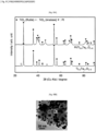
- Fig. 6A shows spectra of results of X-ray diffraction (XDR) measurement performed on the tantalum-doped titanium oxide and the platinum/tantalum-doped titanium oxide.
- the upper spectrum of Fig. 6A represents the diffraction intensity of the platinum/tantalum-doped titanium oxide
- the lower spectrum of Fig. 6A represents the diffraction intensity of the tantalum-doped titanium oxide.
- Fig. 6B shows an image of the platinum/tantalum-doped titanium oxide captured by using a transmission electron microscope (TEM).
- TEM transmission electron microscope
- the image of the platinum/tantalum-doped titanium oxide shown in Fig. 6B which was captured by the TEM, indicates that platinum was uniformly dispersed on the surface of the tantalum-doped titanium oxide.
- the sizes of 500 respective platinum particles were measured from a plurality of images including the image of Fig. 6B .
- the average particle diameter and particle size distribution of the platinum were 6.2 ⁇ 1.9 nm.
- the platinum-carrying rate measured by an inductively coupled plasma mass spectrometer (ICP-MS) was 19.8% by mass.
- Fig. 7 schematically shows a measurement system for the electrical resistance evaluation test, which was conducted under various gas atmospheres.
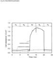
- Fig. 8 is a graph showing changes in the electrical resistance of each of the cell 11 of the working example and the cell 111 of the comparative example under the various gas atmospheres.
- the vertical axis of the graph indicates electrical resistance, and the horizontal axis of the graph indicates time.
- the same gas having a dew point of 75°C was supplied to the anode 16, the anode 166, and the cathodes 17 at the flow rate of 2 L/min.
- three types of gases that are hydrogen, nitrogen, and air were used.
- the electrical resistances of the respective cells 11 and 111 under each gas atmosphere were measured by a low resistance meter having a fixed frequency of 1 kHz.
- the electrical resistance of the cell 11 of the working example exhibited a low value in the case where hydrogen was supplied.
- the electrical resistance of the cell 11 increased rapidly to a value that is about nine times as high as in the case where hydrogen was supplied.
- the electrical resistance of the cell 11 when the anode catalyst layer 19 was under an oxygen atmosphere was nine times or more as high as the electrical resistance of the cell 11 when the anode catalyst layer 19 was under a hydrogen atmosphere.
- the electrical resistance of the cell 111 of the comparative example in the case where air was supplied was about twice as high as in the case where hydrogen was supplied. That is, the difference in the electrical resistance due to the difference in the gas atmosphere was small.
- the electrical resistance under an oxygen atmosphere increased from the electrical resistance under a hydrogen atmosphere to a greater degree than in the case of the cell 111 including the anode catalyst layer 119. That is, the electrical resistance of the cell 11 when the anode catalyst layer 19 was under an oxygen atmosphere was more than twice the electrical resistance of the cell 11 when the anode catalyst layer 19 was under a hydrogen atmosphere.
- Fig. 7 schematically shows a measurement system for the hydrogen pump test.
- Fig. 9 is a graph showing voltage-current characteristics of each of the cell 11 of the working example and the cell 111 of the comparative example in the hydrogen pump test.
- the vertical axis of the graph indicates voltage (V)
- the horizontal axis of the graph indicates current (A/cm 2 ).
- the electrical resistance of each of the cells 11 and 111 in a steady state was obtained.
- the electrical resistance of the cell 11 was 0.125 ⁇ cm 2
- the electrical resistance of the cell 111 was 0.094 ⁇ cm 2 .
- Each of these electrical resistances contains: charge transfer resistances due to oxidation and reduction of hydrogen at the anode 16 or 116 and the cathode 17; and electrical resistances of the polymer electrolyte membrane 15, the catalyst layers 19 or 119 and 20 ( Fig. 4 , Fig. 5 ), the gas diffusion layers 18, and the separators 13 and 14.
- the electrically conductive material of the anode catalyst layer 19 of the anode 16 of the cell 11 is different from the electrically conductive material of the anode catalyst layer 119 of the anode 116 of the cell 111.
- the electrical resistance of the cell 11 and the electrical resistance of the cell 111 measured in situ at 1.5 mAcm 2 by the low resistance meter having a fixed frequency of 1kHz were 0.123 ⁇ cm 2 and 0.092 ⁇ cm 2 , respectively.
- Each of these electrical resistances measured in this manner mainly corresponds to the electrical resistances of the polymer electrolyte membrane 15, the catalyst layers 19 or 119 and 20 ( Fig. 4 and Fig. 5 ), the gas diffusion layers 18, and the separators 13 and 14.
- the difference between the electrical resistance measured in the hydrogen pump test and the electrical resistance measured in situ by the low resistance meter having a fixed frequency of 1kHz was 2 mQcm 2 .
- This difference corresponds to the charge transfer resistances due to oxidation and reduction of hydrogen at the anode 16 or 116 and the cathode 17, and is the same in each of the cells 11 and 111. Since each of the cells 11 and 111 includes the same cathode 17, the charge transfer resistance due to the hydrogen reduction at the cathode 17 is the same in each of the cells 11 and 111. Therefore, the hydrogen oxidation activity at the anode 16 and the hydrogen oxidation activity at the anode 116 are substantially the same degree of activity, and in both cases, overvoltage can be ignored.
- Fig. 10 schematically shows a measurement system for the gas replacement cycle test.
- Fig. 11 is a table showing test conditions of the gas replacement cycle test.
- Fig. 12 is a graph showing a relationship between the number of gas replacement cycles of each of the cell 11 of the working example and the cell 111 of the comparative example and the electrochemically active surface area of Pt of the cathode 17.
- the vertical axis of the graph indicates the electrochemically active surface area (ECSA) of Pt of the cathode
- the horizontal axis of the graph indicates the number of cycles in first to third modes.
- a first mode treatment shown in Fig. 12 was performed, in which non-humidified dry air was supplied to the anode-side channel 23 of each of the cells 11 and 111 for 90 seconds, and humidified air having a dew point of 45°C was supplied to the cathode-side channel 24 of each of the cells 11 and 111 for 90 seconds.
- a second mode treatment was performed, in which humidified hydrogen having a dew point of 45°C was supplied to the anode-side channel 23 of each of the cells 11 and 111 for 90 seconds, and humidified air having a dew point of 45°C was supplied to the cathode-side channel 24 of each of the cells 11 and 111 for 90 seconds.
- a third mode treatment was performed, in which non-humidified dry nitrogen was supplied to the anode-side channel 23 of each of the cells 11 and 111 for 60 seconds, and non-humidified dry nitrogen was supplied to the cathode-side channel 24 of each of the cells 11 and 111 for 60 seconds.
- ECSA m 2 g -1
- Pt platinum
- the ECSA of Pt was calculated by dividing the amount of electricity derived from hydrogen adsorption to Pt by the theoretical value (0.21 mC/cm 2 ) of the amount of electricity derived from hydrogen adsorption to Pt per unit surface area of Pt.
- the amount of electricity derived from hydrogen adsorption to Pt was measured by cyclic voltammetry, in which the cathode-side separator 14 was used as the working electrode, and the anode-side separator 13 was used as the counter electrode and the reference electrode.
- each of the cells 11 and 111 was placed in a temperature environment of 45°C; humidified hydrogen gas having a dew point of 45°C was supplied to the anode-side channel 23; and humidified nitrogen gas having a dew point of 45°C was supplied to the cathode-side channel 24.
- each of the cell 11 of the working example and the cell 111 of the comparative example exhibited decrease in ECSA of Pt.
- the rate of decrease in ECSA of the cell 111 of the comparative example became higher than the rate of decrease in ECSA of the cell 11 of the working example.
- the ECSA retention of the cell 11 after 1000 cycles was 64.7%, whereas the ECSA retention of the cell 111 after 1000 cycles was 42.4%.
- decrease in the catalytic activity of the platinum of the cathode catalyst layer 20 was less than in the cell 111 of the comparative example.
- Fig. 13 schematically shows a measurement system for the power generation performance evaluation test.
- Fig. 14 is a graph showing voltage-current characteristics (IR free) of each of the cell 11 of the working example and the cell 111 of the comparative example in the power generation performance evaluation test.
- the vertical axis of the graph indicates IR free voltage (V) and the horizontal axis of the graph indicates current (A/cm 2 ).
- the temperatures of the cell 11 of the working example and the cell 111 of the comparative example were kept to 65°C.
- Hydrogen having a dew point of 65°C was fed to each of the anode 16 and the anode 116 at such a flow rate that the hydrogen utilization was 70%, and air having a dew point of 65°C was fed to each cathode 17 at such a flow rate that the oxygen utilization was 40%.
- the voltage of each of the cells 11 and 111 during their constant current operation was measured by using an electronic load unit (PLZ-664WA manufactured by KIKUSUI ELECTRONICS CORP.).
- the electrical resistance of each of the cells 11 and 111 was measured in situ by a low resistance meter having a fixed frequency of 1 kHz.
- Fig. 14 shows voltage-current characteristics of each of the cells 11 and 111 before and after the test shown in Fig. 11 (the gas replacement cycle test) was conducted, in which test the series of first to third mode treatments was repeated 1000 times.
- the voltage before the gas replacement cycle test is referred to as a pre-test voltage
- the voltage after the gas replacement cycle test is referred to as a post-test voltage.
- the post-test voltage of the cell 11 was substantially the same value as the post-test voltage of the cell 111, and thus the cell 11 exhibited substantially the same performance as the cell 111.
- the ECSA retention per unit mass at 0.9 V of the cell 11 and that of the cell 111 calculated from Fig. 14 were 51.4% and 39.1%, respectively. These values are substantially the same as the ECSA retention values obtained from Fig. 12 . Therefore, it is considered that deterioration in the performance of the cell 11 at low current densities was due to decrease in ECSA.
- the post-test voltage of the cell 11 was higher than that of the cell 111, and thus the cell 11 exhibited higher performance than the cell 111.
- the difference between the post-test voltage of the cell 11 and the post-test voltage of the cell 111 increased in accordance with increase in the current density. It is considered that such increase in the post-test voltage difference was due to corrosion of the cathode 17 of each of the cells 11 and 111.
- Fig. 15A is a sectional view of the cathode catalyst layer 20 and the polymer electrolyte membrane 15 of the cell 111 before the gas replacement cycle test.
- Fig. 15B is a sectional view of the cathode catalyst layer 20 and the polymer electrolyte membrane 15 of the cell 11 after the gas replacement cycle test.
- Fig. 15C is a sectional view of the cathode catalyst layer 20 and the polymer electrolyte membrane 15 of the cell 111 after the gas replacement cycle test.
- SEM scanning electron microscope
- the cell 11 before the gas replacement cycle test is referred to as a pre-test cell 11; the cell 11 after the gas replacement cycle test is referred to as a post-test cell 11; the cell 111 before the gas replacement cycle test is referred to as a pre-test cell 111; and the cell 111 after the gas replacement cycle test is referred to as a post-test cell 111.
- the thickness of the cathode catalyst layer 20 of the post-test cell 11 was substantially the same as the thickness of the cathode catalyst layer 20 of the pre-test cell 111.
- the thickness of the cathode catalyst layer 20 of the post-test cell 111 was reduced by about 40% compared to the thickness of the cathode catalyst layer 20 of the pre-test cell 111.
- the cathode catalyst layer of the post-test cell 111 easily detached from the polymer electrolyte membrane 15. Such detachment of the cathode catalyst layer 20 from the polymer electrolyte membrane 15 was not seen in the post-test cell 11.
- the carbon of the cathode catalyst layer 20 of the cell 111 corroded to a greater degree than the carbon of the cathode catalyst layer 20 of the cell 11.
- the corrosion of the cathode catalyst layer 20 causes significant reduction in mass transfer.
- the difference in performance between the cell 11 and the cell 111 at high current densities is due to the difference between the cell 11 and the cell 111 in terms of the degree of corrosion of the carbon of the cathode catalyst layer 20 in the gas replacement cycle test.
- the cell, the fuel cell stack, the fuel cell system, and the membrane electrode assembly of the present invention are useful, for example, as a cell, a fuel cell stack, a fuel cell system, and a membrane electrode assembly that are capable of suppressing deterioration in power generation performance while suppressing increase in their size and cost.
Landscapes
- Chemical & Material Sciences (AREA)
- Chemical Kinetics & Catalysis (AREA)
- Electrochemistry (AREA)
- General Chemical & Material Sciences (AREA)
- Engineering & Computer Science (AREA)
- Sustainable Development (AREA)
- Life Sciences & Earth Sciences (AREA)
- Manufacturing & Machinery (AREA)
- Materials Engineering (AREA)
- Sustainable Energy (AREA)
- Organic Chemistry (AREA)
- Composite Materials (AREA)
- Fuel Cell (AREA)
- Inert Electrodes (AREA)
Claims (12)
- Cellule comprenant :un assemblage membrane-électrode (12) ; etune paire de séparateurs (13, 14), entre lesquels l'assemblage membrane-électrode (12) est interposé, dans laquellel'assemblage membrane-électrode (12) inclut une membrane électrolytique polymère (15), une couche catalytique anodique (19) disposée sur une première surface principale de la membrane électrolytique polymère (15), et une couche catalytique cathodique (20) disposée sur une deuxième surface principale de la membrane électrolytique polymère (15),la couche catalytique anodique (19) contient un premier matériau catalytique ayant une activité contre une réaction d'oxydation de l'hydrogène et un premier matériau électriquement conducteur dont la résistance électrique sous une atmosphère d'hydrogène et la résistance électrique sous une atmosphère d'oxygène sont différentes l'une de l'autre,le premier matériau catalytique est supporté sur une surface du premier matériau électriquement conducteur,le premier matériau électriquement conducteur est un oxyde de titane dopé avec un métal différent,la couche catalytique cathodique (20) contient un deuxième matériau catalytique ayant une activité contre une réaction de réduction de l'oxygène et un deuxième matériau électriquement conducteur différent du premier matériau électriquement conducteur, etla résistance électrique de la cellule lorsque la couche catalytique anodique (19) est sous atmosphère d'oxygène est plus de deux fois supérieure à la résistance électrique de la cellule lorsque la couche catalytique anodique (19) est sous atmosphère d'hydrogène.
- Cellule selon la revendication 1, dans laquelle la couche catalytique anodique (19) contient un liant conducteur d'ions.
- Cellule selon la revendication 1 ou 2, dans laquelle
le deuxième matériau électriquement conducteur est du carbone. - Cellule selon l'une quelconque des revendications 1 à 3, dans laquellele premier matériau électriquement conducteur est formé de particules, etle diamètre primaire moyen des particules n'est pas inférieur à 10 nm ni supérieur à 1 000 nm.
- Cellule selon l'une quelconque des revendications 1 à 4, dans laquelle le premier matériau catalytique contient du platine ou un alliage de platine.
- Cellule selon l'une quelconque des revendications 1 à 5, dans laquellele premier matériau catalytique est formé de particules, etle diamètre primaire moyen des particules n'est pas inférieur à 1 nm ni supérieur à 10 nm.
- Cellule selon l'une quelconque des revendications 1 à 6, dans laquelle la résistance électrique de la cellule lorsque la couche catalytique anodique (19) est sous atmosphère d'oxygène est neuf fois ou plus élevée que la résistance électrique de la cellule lorsque la couche catalytique anodique (19) est sous atmosphère d'hydrogène.
- Cellule selon l'une quelconque des revendications 1 à 7, dans laquelle le deuxième matériau électriquement conducteur a une propriété de changement de résistance inférieure à celle du premier matériau électriquement conducteur.
- Cellule selon l'une quelconque des revendications 1 à 8, dans laquelle le deuxième matériau électriquement conducteur est du noir de carbone.
- Pile à combustible comprenant une pluralité de cellules selon l'une quelconque des revendications 1 à 9, les cellules étant empilées les unes sur les autres.
- Système de pile à combustible comprenant :un empilement de piles à combustible (10) incluant une pluralité de cellules (11) selon l'une quelconque des revendications 1 à 9, les cellules étant empilées les unes sur les autres ;un dispositif d'alimentation en gaz combustible (30) configuré pour alimenter en gaz combustible un canal de la paire de séparateurs (13, 14) ; etun dispositif d'alimentation en gaz oxydant (50) configuré pour fournir un gaz oxydant à un autre canal de la paire de séparateurs (13, 14).
- Assemblage membrane-électrode comprenant :une membrane électrolytique polymère (15) ;une couche catalytique anodique (19) disposée sur une première surface principale de la membrane électrolytique polymère (15) ; etune couche catalytique cathodique (20) disposée sur une deuxième surface principale de la membrane électrolytique polymère (15), dans lequella couche catalytique anodique (19) contient un premier matériau catalytique ayant une activité contre une réaction d'oxydation de l'hydrogène et un premier matériau électriquement conducteur dont la résistance électrique sous une atmosphère d'hydrogène et la résistance électrique sous une atmosphère d'oxygène sont différentes l'une de l'autre,le premier matériau catalytique est supporté sur une surface du premier matériau électriquement conducteur,le premier matériau électriquement conducteur est un oxyde de titane dopé avec un métal différent,la couche catalytique cathodique (20) contient un deuxième matériau catalytique ayant une activité contre une réaction de réduction de l'oxygène et un deuxième matériau électriquement conducteur différent du premier matériau électriquement conducteur, etla résistance électrique de la cellule lorsque la couche catalytique anodique (19) est sous atmosphère d'oxygène est plus de deux fois supérieure à la résistance électrique de la cellule lorsque la couche catalytique anodique (19) est sous atmosphère d'hydrogène.
Applications Claiming Priority (2)
| Application Number | Priority Date | Filing Date | Title |
|---|---|---|---|
| JP2015121434 | 2015-06-16 | ||
| PCT/JP2016/001691 WO2016203679A1 (fr) | 2015-06-16 | 2016-03-23 | Pile, empilement de piles à combustible, système de pile à combustible et corps assemblé par un ensemble membrane-électrode |
Publications (3)
| Publication Number | Publication Date |
|---|---|
| EP3312921A1 EP3312921A1 (fr) | 2018-04-25 |
| EP3312921A4 EP3312921A4 (fr) | 2018-05-16 |
| EP3312921B1 true EP3312921B1 (fr) | 2023-10-25 |
Family
ID=57545714
Family Applications (1)
| Application Number | Title | Priority Date | Filing Date |
|---|---|---|---|
| EP16811160.7A Active EP3312921B1 (fr) | 2015-06-16 | 2016-03-23 | Pile, empilement de piles à combustible, système de pile à combustible et corps assemblé par un ensemble membrane-électrode |
Country Status (4)
| Country | Link |
|---|---|
| US (1) | US20180175397A1 (fr) |
| EP (1) | EP3312921B1 (fr) |
| JP (1) | JP6150265B2 (fr) |
| WO (1) | WO2016203679A1 (fr) |
Families Citing this family (8)
| Publication number | Priority date | Publication date | Assignee | Title |
|---|---|---|---|---|
| JP3086980B2 (ja) | 1992-03-03 | 2000-09-11 | 古野電気株式会社 | 水中探知装置 |
| WO2019021904A1 (fr) * | 2017-07-25 | 2019-01-31 | 国立大学法人山梨大学 | Poudre de support ainsi que procédé de fabrication de celle-ci, et catalyseur métallique sur support ainsi que procédé de fabrication de celle-ci |
| JP7190099B2 (ja) | 2019-01-30 | 2022-12-15 | 国立大学法人山梨大学 | 担持金属触媒及びその製造方法、燃料電池セル |
| JP7678452B2 (ja) | 2019-12-13 | 2025-05-16 | 国立大学法人山梨大学 | 担持金属触媒、電気化学セル |
| EP4113669B1 (fr) * | 2020-02-27 | 2025-12-24 | Mitsui Mining & Smelting Co., Ltd. | Couche de catalyseur d'électrode pour pile à combustible, et pile à combustible de type polymère solide comprenant ladite couche de catalyseur d'électrode |
| CN113422079B (zh) * | 2021-05-21 | 2022-09-09 | 深圳航天科技创新研究院 | 一种燃料电池催化剂的热处理控制方法 |
| EP4456204A4 (fr) * | 2021-12-21 | 2025-12-24 | Cataler Corp | Procédé de production de particules d'oxyde conducteur contenant un métal noble catalytique |
| CN115394368B (zh) * | 2022-08-19 | 2025-09-02 | 西安交通大学 | 基于催化层碳腐蚀的电池性能预测方法 |
Citations (1)
| Publication number | Priority date | Publication date | Assignee | Title |
|---|---|---|---|---|
| US20090312181A1 (en) * | 2008-06-11 | 2009-12-17 | Gm Global Technology Operations, Inc. | Mesoporous electrically conductive metal oxide catalyst supports |
Family Cites Families (10)
| Publication number | Priority date | Publication date | Assignee | Title |
|---|---|---|---|---|
| JP3236686B2 (ja) * | 1992-12-25 | 2001-12-10 | ペルメレック電極株式会社 | ガス電極とその製造方法 |
| JP2002280002A (ja) * | 2001-03-16 | 2002-09-27 | Mitsubishi Heavy Ind Ltd | 固体高分子型燃料電池及びその損傷防止方法 |
| JP2006019133A (ja) * | 2004-07-01 | 2006-01-19 | Nitto Denko Corp | 燃料電池用アノード電極 |
| JP2009026501A (ja) * | 2007-07-17 | 2009-02-05 | Nissan Motor Co Ltd | 電解質膜−電極接合体 |
| KR101363797B1 (ko) * | 2007-11-09 | 2014-02-14 | 고쿠리쓰다이가쿠호진 규슈다이가쿠 | 연료전지용 전극재료의 제조방법, 연료전지용 전극재료 및 이 연료전지 전극재료를 이용한 연료전지 |
| US20140004444A1 (en) * | 2010-09-28 | 2014-01-02 | Isotta Cerri | Fuel cell electrocatalyst |
| GB2509916A (en) * | 2013-01-16 | 2014-07-23 | Ilika Technologies Ltd | A mixed metal oxide material of tantalum and titanium |
| JP6345663B2 (ja) * | 2013-07-05 | 2018-06-20 | 国立大学法人九州大学 | 燃料電池用電極及びその製造方法、並びに膜電極接合体及び固体高分子形燃料電池 |
| JP6624711B2 (ja) * | 2014-03-20 | 2019-12-25 | 国立大学法人九州大学 | 燃料電池用アノード電極材料およびその製造方法、並びに燃料電池用電極、膜電極接合体及び固体高分子形燃料電池 |
| JP6748953B2 (ja) * | 2015-08-11 | 2020-09-02 | 国立大学法人山梨大学 | 燃料電池システム及びその運用方法 |
-
2016
- 2016-03-23 JP JP2016563221A patent/JP6150265B2/ja active Active
- 2016-03-23 US US15/737,091 patent/US20180175397A1/en not_active Abandoned
- 2016-03-23 WO PCT/JP2016/001691 patent/WO2016203679A1/fr not_active Ceased
- 2016-03-23 EP EP16811160.7A patent/EP3312921B1/fr active Active
Patent Citations (1)
| Publication number | Priority date | Publication date | Assignee | Title |
|---|---|---|---|---|
| US20090312181A1 (en) * | 2008-06-11 | 2009-12-17 | Gm Global Technology Operations, Inc. | Mesoporous electrically conductive metal oxide catalyst supports |
Also Published As
| Publication number | Publication date |
|---|---|
| JP6150265B2 (ja) | 2017-06-21 |
| JPWO2016203679A1 (ja) | 2017-06-29 |
| US20180175397A1 (en) | 2018-06-21 |
| EP3312921A4 (fr) | 2018-05-16 |
| EP3312921A1 (fr) | 2018-04-25 |
| WO2016203679A1 (fr) | 2016-12-22 |
Similar Documents
| Publication | Publication Date | Title |
|---|---|---|
| EP3312921B1 (fr) | Pile, empilement de piles à combustible, système de pile à combustible et corps assemblé par un ensemble membrane-électrode | |
| CA2758432C (fr) | Composition de catalyseur cote anode pour pile a combustible et ensemble membrane-electrode (mea) pour pile a combustible de type polymere solide | |
| US8398884B2 (en) | Method for producing electrode material for fuel cell, electrode material for fuel cell, and fuel cell using the electrode material for fuel cell | |
| EP3719898B1 (fr) | Couche de catalyseur | |
| US10243218B2 (en) | Method for producing fine catalyst particles, method for producing carbon-supported fine catalyst particles, method for producing catalyst mix and method for producing electrode | |
| US9825307B2 (en) | Anode-side catalyst composition for fuel cells, and membrane electrode assembly (MEA) for solid polymer fuel cells which comprises same | |
| US8329129B2 (en) | Method for preparing pyrochlore oxide, polymer electrolyte fuel cell, fuel cell system, and method for producing electro catalyst for fuel cell | |
| JP4197683B2 (ja) | 燃料電池電極用触媒、燃料電池電極、膜電極接合体および燃料電池 | |
| Shintani et al. | Novel strategy to mitigate cathode catalyst degradation during air/air startup cycling via the atmospheric resistive switching mechanism of a hydrogen anode with a platinum catalyst supported on tantalum-doped titanium dioxide | |
| JPWO2007119640A1 (ja) | 燃料電池用電極触媒及びその製造方法 | |
| KR20190059953A (ko) | 전기화학적 연료 전지를 위한 캐소드 전극 설계 | |
| JP6727266B2 (ja) | 燃料電池用アノード触媒層及びそれを用いた燃料電池 | |
| WO2020059503A1 (fr) | Couche de catalyseur d'anode pour pile à combustible et pile à combustible l'utilisant | |
| US9899686B2 (en) | Method for producing fuel cell catalyst | |
| Hassan et al. | Effect of addition of Ru and/or Fe in the stability of PtMo/C electrocatalysts in proton exchange membrane fuel cells | |
| CN104205447B (zh) | 燃料电池用电极催化剂的制造方法、燃料电池用电极催化剂及其用途 | |
| JP6727265B2 (ja) | 燃料電池用アノード触媒層及びそれを用いた燃料電池 | |
| WO2020059502A1 (fr) | Couche catalytique d'anode pour pile à combustible et pile à combustible l'utilisant | |
| JP2009070673A (ja) | 固体高分子形燃料電池用触媒及び固体高分子形燃料電池用電極 | |
| HK1165095A (en) | Anode-side catalyst composition for fuel cell and membrane electrode assembly (mea) for solid polymer-type fuel cell | |
| HK1165095B (en) | Anode-side catalyst composition for fuel cell and membrane electrode assembly (mea) for solid polymer-type fuel cell |
Legal Events
| Date | Code | Title | Description |
|---|---|---|---|
| STAA | Information on the status of an ep patent application or granted ep patent |
Free format text: STATUS: THE INTERNATIONAL PUBLICATION HAS BEEN MADE |
|
| PUAI | Public reference made under article 153(3) epc to a published international application that has entered the european phase |
Free format text: ORIGINAL CODE: 0009012 |
|
| STAA | Information on the status of an ep patent application or granted ep patent |
Free format text: STATUS: REQUEST FOR EXAMINATION WAS MADE |
|
| 17P | Request for examination filed |
Effective date: 20171213 |
|
| AK | Designated contracting states |
Kind code of ref document: A1 Designated state(s): AL AT BE BG CH CY CZ DE DK EE ES FI FR GB GR HR HU IE IS IT LI LT LU LV MC MK MT NL NO PL PT RO RS SE SI SK SM TR |
|
| AX | Request for extension of the european patent |
Extension state: BA ME |
|
| A4 | Supplementary search report drawn up and despatched |
Effective date: 20180416 |
|
| RIC1 | Information provided on ipc code assigned before grant |
Ipc: B01J 23/648 20060101ALI20180406BHEP Ipc: H01M 4/86 20060101AFI20180406BHEP Ipc: H01M 4/90 20060101ALI20180406BHEP Ipc: H01M 8/02 20160101ALI20180406BHEP Ipc: H01M 4/92 20060101ALI20180406BHEP Ipc: H01M 8/1004 20160101ALI20180406BHEP Ipc: B01J 23/42 20060101ALI20180406BHEP Ipc: H01M 8/10 20160101ALI20180406BHEP Ipc: H01M 8/1018 20160101ALN20180406BHEP |
|
| DAV | Request for validation of the european patent (deleted) | ||
| DAX | Request for extension of the european patent (deleted) | ||
| STAA | Information on the status of an ep patent application or granted ep patent |
Free format text: STATUS: EXAMINATION IS IN PROGRESS |
|
| 17Q | First examination report despatched |
Effective date: 20220325 |
|
| RAP3 | Party data changed (applicant data changed or rights of an application transferred) |
Owner name: NATIONAL UNIVERSITY CORPORATION UNIVERSITY OF YAMANASHI Owner name: PANASONIC HOLDINGS CORPORATION |
|
| RIC1 | Information provided on ipc code assigned before grant |
Ipc: H01M 8/1018 20160101ALN20230331BHEP Ipc: H01M 8/1004 20160101ALI20230331BHEP Ipc: H01M 8/10 20160101ALI20230331BHEP Ipc: H01M 8/02 20160101ALI20230331BHEP Ipc: H01M 4/92 20060101ALI20230331BHEP Ipc: H01M 4/90 20060101ALI20230331BHEP Ipc: B01J 23/648 20060101ALI20230331BHEP Ipc: B01J 23/42 20060101ALI20230331BHEP Ipc: H01M 4/86 20060101AFI20230331BHEP |
|
| GRAP | Despatch of communication of intention to grant a patent |
Free format text: ORIGINAL CODE: EPIDOSNIGR1 |
|
| STAA | Information on the status of an ep patent application or granted ep patent |
Free format text: STATUS: GRANT OF PATENT IS INTENDED |
|
| RIC1 | Information provided on ipc code assigned before grant |
Ipc: H01M 8/1018 20160101ALN20230503BHEP Ipc: H01M 8/1004 20160101ALI20230503BHEP Ipc: H01M 8/10 20160101ALI20230503BHEP Ipc: H01M 8/02 20160101ALI20230503BHEP Ipc: H01M 4/92 20060101ALI20230503BHEP Ipc: H01M 4/90 20060101ALI20230503BHEP Ipc: B01J 23/648 20060101ALI20230503BHEP Ipc: B01J 23/42 20060101ALI20230503BHEP Ipc: H01M 4/86 20060101AFI20230503BHEP |
|
| INTG | Intention to grant announced |
Effective date: 20230519 |
|
| GRAS | Grant fee paid |
Free format text: ORIGINAL CODE: EPIDOSNIGR3 |
|
| GRAA | (expected) grant |
Free format text: ORIGINAL CODE: 0009210 |
|
| STAA | Information on the status of an ep patent application or granted ep patent |
Free format text: STATUS: THE PATENT HAS BEEN GRANTED |
|
| AK | Designated contracting states |
Kind code of ref document: B1 Designated state(s): AL AT BE BG CH CY CZ DE DK EE ES FI FR GB GR HR HU IE IS IT LI LT LU LV MC MK MT NL NO PL PT RO RS SE SI SK SM TR |
|
| REG | Reference to a national code |
Ref country code: GB Ref legal event code: FG4D |
|
| REG | Reference to a national code |
Ref country code: CH Ref legal event code: EP |
|
| REG | Reference to a national code |
Ref country code: DE Ref legal event code: R096 Ref document number: 602016083708 Country of ref document: DE |
|
| REG | Reference to a national code |
Ref country code: IE Ref legal event code: FG4D |
|
| REG | Reference to a national code |
Ref country code: LT Ref legal event code: MG9D |
|
| REG | Reference to a national code |
Ref country code: NL Ref legal event code: MP Effective date: 20231025 |
|
| REG | Reference to a national code |
Ref country code: AT Ref legal event code: MK05 Ref document number: 1625594 Country of ref document: AT Kind code of ref document: T Effective date: 20231025 |
|
| PG25 | Lapsed in a contracting state [announced via postgrant information from national office to epo] |
Ref country code: NL Free format text: LAPSE BECAUSE OF FAILURE TO SUBMIT A TRANSLATION OF THE DESCRIPTION OR TO PAY THE FEE WITHIN THE PRESCRIBED TIME-LIMIT Effective date: 20231025 |
|
| PG25 | Lapsed in a contracting state [announced via postgrant information from national office to epo] |
Ref country code: GR Free format text: LAPSE BECAUSE OF FAILURE TO SUBMIT A TRANSLATION OF THE DESCRIPTION OR TO PAY THE FEE WITHIN THE PRESCRIBED TIME-LIMIT Effective date: 20240126 |
|
| PG25 | Lapsed in a contracting state [announced via postgrant information from national office to epo] |
Ref country code: IS Free format text: LAPSE BECAUSE OF FAILURE TO SUBMIT A TRANSLATION OF THE DESCRIPTION OR TO PAY THE FEE WITHIN THE PRESCRIBED TIME-LIMIT Effective date: 20240225 |
|
| PG25 | Lapsed in a contracting state [announced via postgrant information from national office to epo] |
Ref country code: LT Free format text: LAPSE BECAUSE OF FAILURE TO SUBMIT A TRANSLATION OF THE DESCRIPTION OR TO PAY THE FEE WITHIN THE PRESCRIBED TIME-LIMIT Effective date: 20231025 |
|
| PG25 | Lapsed in a contracting state [announced via postgrant information from national office to epo] |
Ref country code: AT Free format text: LAPSE BECAUSE OF FAILURE TO SUBMIT A TRANSLATION OF THE DESCRIPTION OR TO PAY THE FEE WITHIN THE PRESCRIBED TIME-LIMIT Effective date: 20231025 |
|
| PG25 | Lapsed in a contracting state [announced via postgrant information from national office to epo] |
Ref country code: ES Free format text: LAPSE BECAUSE OF FAILURE TO SUBMIT A TRANSLATION OF THE DESCRIPTION OR TO PAY THE FEE WITHIN THE PRESCRIBED TIME-LIMIT Effective date: 20231025 |
|
| PG25 | Lapsed in a contracting state [announced via postgrant information from national office to epo] |
Ref country code: LT Free format text: LAPSE BECAUSE OF FAILURE TO SUBMIT A TRANSLATION OF THE DESCRIPTION OR TO PAY THE FEE WITHIN THE PRESCRIBED TIME-LIMIT Effective date: 20231025 Ref country code: IS Free format text: LAPSE BECAUSE OF FAILURE TO SUBMIT A TRANSLATION OF THE DESCRIPTION OR TO PAY THE FEE WITHIN THE PRESCRIBED TIME-LIMIT Effective date: 20240225 Ref country code: GR Free format text: LAPSE BECAUSE OF FAILURE TO SUBMIT A TRANSLATION OF THE DESCRIPTION OR TO PAY THE FEE WITHIN THE PRESCRIBED TIME-LIMIT Effective date: 20240126 Ref country code: ES Free format text: LAPSE BECAUSE OF FAILURE TO SUBMIT A TRANSLATION OF THE DESCRIPTION OR TO PAY THE FEE WITHIN THE PRESCRIBED TIME-LIMIT Effective date: 20231025 Ref country code: BG Free format text: LAPSE BECAUSE OF FAILURE TO SUBMIT A TRANSLATION OF THE DESCRIPTION OR TO PAY THE FEE WITHIN THE PRESCRIBED TIME-LIMIT Effective date: 20240125 Ref country code: AT Free format text: LAPSE BECAUSE OF FAILURE TO SUBMIT A TRANSLATION OF THE DESCRIPTION OR TO PAY THE FEE WITHIN THE PRESCRIBED TIME-LIMIT Effective date: 20231025 Ref country code: PT Free format text: LAPSE BECAUSE OF FAILURE TO SUBMIT A TRANSLATION OF THE DESCRIPTION OR TO PAY THE FEE WITHIN THE PRESCRIBED TIME-LIMIT Effective date: 20240226 |
|
| PG25 | Lapsed in a contracting state [announced via postgrant information from national office to epo] |
Ref country code: SE Free format text: LAPSE BECAUSE OF FAILURE TO SUBMIT A TRANSLATION OF THE DESCRIPTION OR TO PAY THE FEE WITHIN THE PRESCRIBED TIME-LIMIT Effective date: 20231025 Ref country code: RS Free format text: LAPSE BECAUSE OF FAILURE TO SUBMIT A TRANSLATION OF THE DESCRIPTION OR TO PAY THE FEE WITHIN THE PRESCRIBED TIME-LIMIT Effective date: 20231025 Ref country code: PL Free format text: LAPSE BECAUSE OF FAILURE TO SUBMIT A TRANSLATION OF THE DESCRIPTION OR TO PAY THE FEE WITHIN THE PRESCRIBED TIME-LIMIT Effective date: 20231025 Ref country code: NO Free format text: LAPSE BECAUSE OF FAILURE TO SUBMIT A TRANSLATION OF THE DESCRIPTION OR TO PAY THE FEE WITHIN THE PRESCRIBED TIME-LIMIT Effective date: 20240125 Ref country code: LV Free format text: LAPSE BECAUSE OF FAILURE TO SUBMIT A TRANSLATION OF THE DESCRIPTION OR TO PAY THE FEE WITHIN THE PRESCRIBED TIME-LIMIT Effective date: 20231025 Ref country code: HR Free format text: LAPSE BECAUSE OF FAILURE TO SUBMIT A TRANSLATION OF THE DESCRIPTION OR TO PAY THE FEE WITHIN THE PRESCRIBED TIME-LIMIT Effective date: 20231025 |
|
| PG25 | Lapsed in a contracting state [announced via postgrant information from national office to epo] |
Ref country code: DK Free format text: LAPSE BECAUSE OF FAILURE TO SUBMIT A TRANSLATION OF THE DESCRIPTION OR TO PAY THE FEE WITHIN THE PRESCRIBED TIME-LIMIT Effective date: 20231025 |
|
| PG25 | Lapsed in a contracting state [announced via postgrant information from national office to epo] |
Ref country code: CZ Free format text: LAPSE BECAUSE OF FAILURE TO SUBMIT A TRANSLATION OF THE DESCRIPTION OR TO PAY THE FEE WITHIN THE PRESCRIBED TIME-LIMIT Effective date: 20231025 |
|
| REG | Reference to a national code |
Ref country code: DE Ref legal event code: R097 Ref document number: 602016083708 Country of ref document: DE |
|
| PG25 | Lapsed in a contracting state [announced via postgrant information from national office to epo] |
Ref country code: SK Free format text: LAPSE BECAUSE OF FAILURE TO SUBMIT A TRANSLATION OF THE DESCRIPTION OR TO PAY THE FEE WITHIN THE PRESCRIBED TIME-LIMIT Effective date: 20231025 |
|
| PG25 | Lapsed in a contracting state [announced via postgrant information from national office to epo] |
Ref country code: SM Free format text: LAPSE BECAUSE OF FAILURE TO SUBMIT A TRANSLATION OF THE DESCRIPTION OR TO PAY THE FEE WITHIN THE PRESCRIBED TIME-LIMIT Effective date: 20231025 Ref country code: SK Free format text: LAPSE BECAUSE OF FAILURE TO SUBMIT A TRANSLATION OF THE DESCRIPTION OR TO PAY THE FEE WITHIN THE PRESCRIBED TIME-LIMIT Effective date: 20231025 Ref country code: RO Free format text: LAPSE BECAUSE OF FAILURE TO SUBMIT A TRANSLATION OF THE DESCRIPTION OR TO PAY THE FEE WITHIN THE PRESCRIBED TIME-LIMIT Effective date: 20231025 Ref country code: IT Free format text: LAPSE BECAUSE OF FAILURE TO SUBMIT A TRANSLATION OF THE DESCRIPTION OR TO PAY THE FEE WITHIN THE PRESCRIBED TIME-LIMIT Effective date: 20231025 Ref country code: EE Free format text: LAPSE BECAUSE OF FAILURE TO SUBMIT A TRANSLATION OF THE DESCRIPTION OR TO PAY THE FEE WITHIN THE PRESCRIBED TIME-LIMIT Effective date: 20231025 Ref country code: DK Free format text: LAPSE BECAUSE OF FAILURE TO SUBMIT A TRANSLATION OF THE DESCRIPTION OR TO PAY THE FEE WITHIN THE PRESCRIBED TIME-LIMIT Effective date: 20231025 Ref country code: CZ Free format text: LAPSE BECAUSE OF FAILURE TO SUBMIT A TRANSLATION OF THE DESCRIPTION OR TO PAY THE FEE WITHIN THE PRESCRIBED TIME-LIMIT Effective date: 20231025 |
|
| PLBE | No opposition filed within time limit |
Free format text: ORIGINAL CODE: 0009261 |
|
| STAA | Information on the status of an ep patent application or granted ep patent |
Free format text: STATUS: NO OPPOSITION FILED WITHIN TIME LIMIT |
|
| 26N | No opposition filed |
Effective date: 20240726 |
|
| PG25 | Lapsed in a contracting state [announced via postgrant information from national office to epo] |
Ref country code: SI Free format text: LAPSE BECAUSE OF FAILURE TO SUBMIT A TRANSLATION OF THE DESCRIPTION OR TO PAY THE FEE WITHIN THE PRESCRIBED TIME-LIMIT Effective date: 20231025 |
|
| PG25 | Lapsed in a contracting state [announced via postgrant information from national office to epo] |
Ref country code: SI Free format text: LAPSE BECAUSE OF FAILURE TO SUBMIT A TRANSLATION OF THE DESCRIPTION OR TO PAY THE FEE WITHIN THE PRESCRIBED TIME-LIMIT Effective date: 20231025 |
|
| REG | Reference to a national code |
Ref country code: CH Ref legal event code: PL |
|
| PG25 | Lapsed in a contracting state [announced via postgrant information from national office to epo] |
Ref country code: LU Free format text: LAPSE BECAUSE OF NON-PAYMENT OF DUE FEES Effective date: 20240323 |
|
| PG25 | Lapsed in a contracting state [announced via postgrant information from national office to epo] |
Ref country code: MC Free format text: LAPSE BECAUSE OF FAILURE TO SUBMIT A TRANSLATION OF THE DESCRIPTION OR TO PAY THE FEE WITHIN THE PRESCRIBED TIME-LIMIT Effective date: 20231025 |
|
| GBPC | Gb: european patent ceased through non-payment of renewal fee |
Effective date: 20240323 |
|
| PG25 | Lapsed in a contracting state [announced via postgrant information from national office to epo] |
Ref country code: MC Free format text: LAPSE BECAUSE OF FAILURE TO SUBMIT A TRANSLATION OF THE DESCRIPTION OR TO PAY THE FEE WITHIN THE PRESCRIBED TIME-LIMIT Effective date: 20231025 Ref country code: LU Free format text: LAPSE BECAUSE OF NON-PAYMENT OF DUE FEES Effective date: 20240323 |
|
| REG | Reference to a national code |
Ref country code: BE Ref legal event code: MM Effective date: 20240331 |
|
| PG25 | Lapsed in a contracting state [announced via postgrant information from national office to epo] |
Ref country code: BE Free format text: LAPSE BECAUSE OF NON-PAYMENT OF DUE FEES Effective date: 20240331 |
|
| PG25 | Lapsed in a contracting state [announced via postgrant information from national office to epo] |
Ref country code: GB Free format text: LAPSE BECAUSE OF NON-PAYMENT OF DUE FEES Effective date: 20240323 |
|
| PG25 | Lapsed in a contracting state [announced via postgrant information from national office to epo] |
Ref country code: FR Free format text: LAPSE BECAUSE OF NON-PAYMENT OF DUE FEES Effective date: 20240331 |
|
| PG25 | Lapsed in a contracting state [announced via postgrant information from national office to epo] |
Ref country code: IE Free format text: LAPSE BECAUSE OF NON-PAYMENT OF DUE FEES Effective date: 20240323 |
|
| PG25 | Lapsed in a contracting state [announced via postgrant information from national office to epo] |
Ref country code: IE Free format text: LAPSE BECAUSE OF NON-PAYMENT OF DUE FEES Effective date: 20240323 Ref country code: GB Free format text: LAPSE BECAUSE OF NON-PAYMENT OF DUE FEES Effective date: 20240323 Ref country code: FR Free format text: LAPSE BECAUSE OF NON-PAYMENT OF DUE FEES Effective date: 20240331 Ref country code: BE Free format text: LAPSE BECAUSE OF NON-PAYMENT OF DUE FEES Effective date: 20240331 Ref country code: CH Free format text: LAPSE BECAUSE OF NON-PAYMENT OF DUE FEES Effective date: 20240331 |
|
| PG25 | Lapsed in a contracting state [announced via postgrant information from national office to epo] |
Ref country code: CY Free format text: LAPSE BECAUSE OF FAILURE TO SUBMIT A TRANSLATION OF THE DESCRIPTION OR TO PAY THE FEE WITHIN THE PRESCRIBED TIME-LIMIT; INVALID AB INITIO Effective date: 20160323 |
|
| PG25 | Lapsed in a contracting state [announced via postgrant information from national office to epo] |
Ref country code: HU Free format text: LAPSE BECAUSE OF FAILURE TO SUBMIT A TRANSLATION OF THE DESCRIPTION OR TO PAY THE FEE WITHIN THE PRESCRIBED TIME-LIMIT; INVALID AB INITIO Effective date: 20160323 |
|
| PG25 | Lapsed in a contracting state [announced via postgrant information from national office to epo] |
Ref country code: FI Free format text: LAPSE BECAUSE OF FAILURE TO SUBMIT A TRANSLATION OF THE DESCRIPTION OR TO PAY THE FEE WITHIN THE PRESCRIBED TIME-LIMIT Effective date: 20231025 |
|
| PG25 | Lapsed in a contracting state [announced via postgrant information from national office to epo] |
Ref country code: TR Free format text: LAPSE BECAUSE OF FAILURE TO SUBMIT A TRANSLATION OF THE DESCRIPTION OR TO PAY THE FEE WITHIN THE PRESCRIBED TIME-LIMIT Effective date: 20231025 |
|
| PGFP | Annual fee paid to national office [announced via postgrant information from national office to epo] |
Ref country code: DE Payment date: 20260102 Year of fee payment: 11 |