EP3312944A1 - Partie connecteur accouplable push-pull dotée d'une tôle d'arrêt - Google Patents
Partie connecteur accouplable push-pull dotée d'une tôle d'arrêt Download PDFInfo
- Publication number
- EP3312944A1 EP3312944A1 EP17197142.7A EP17197142A EP3312944A1 EP 3312944 A1 EP3312944 A1 EP 3312944A1 EP 17197142 A EP17197142 A EP 17197142A EP 3312944 A1 EP3312944 A1 EP 3312944A1
- Authority
- EP
- European Patent Office
- Prior art keywords
- connector part
- latching
- actuating element
- housing part
- mating connector
- Prior art date
- Legal status (The legal status is an assumption and is not a legal conclusion. Google has not performed a legal analysis and makes no representation as to the accuracy of the status listed.)
- Granted
Links
Images


Classifications
-
- H—ELECTRICITY
- H01—ELECTRIC ELEMENTS
- H01R—ELECTRICALLY-CONDUCTIVE CONNECTIONS; STRUCTURAL ASSOCIATIONS OF A PLURALITY OF MUTUALLY-INSULATED ELECTRICAL CONNECTING ELEMENTS; COUPLING DEVICES; CURRENT COLLECTORS
- H01R13/00—Details of coupling devices of the kinds covered by groups H01R12/70 or H01R24/00 - H01R33/00
- H01R13/62—Means for facilitating engagement or disengagement of coupling parts or for holding them in engagement
- H01R13/627—Snap or like fastening
- H01R13/6275—Latching arms not integral with the housing
Definitions
- the invention relates to a connector part according to the preamble of claim 1.
- a male part is meant in this context e.g. a plug attached to the end of a cable or a built-in connector in a device housing.
- a female part is understood to mean, for example, a mounted at the end of a line coupling or built-in a device housing socket.
- the male part can be inserted into the female part and has for this purpose e.g. protruding contact pins which are to be inserted into associated contact openings of the female part.
- Known connector for optical fibers comprises a connector housing, are held on the optical waveguide with ferrules disposed thereon.
- the connector housing can be plugged with the optical fibers arranged thereon in an associated socket or a coupling in order to produce an optical contact in this way.
- a sliding sleeve is arranged, which serves to release a latching between the connector housing and an associated socket or coupling for removing the connector housing from the socket or the coupling.
- a connector part in which a latching element is integrally formed with a housing part.
- Object of the present invention is to provide a connector part available that is reliably locked in a position infected to the associated mating connector part position and in which an unintentional release is at least difficult.
- the actuating element is provided, for example, by one or more spring elements, e.g. in the form of compression springs relative to the housing part in the plug-in direction spring biased.
- a latching plate and a spring element may be provided on both sides of the housing part.
- a first latching plate is thus arranged on a first side of the housing part and a second latching plate in a symmetrical manner on a second side of the housing part facing away from the first side.
- the first side and the second side in each case a spring element is assigned, so that the actuating element on the sides of the housing part, on which a latching plate is arranged, is also spring-biased relative to the housing part.
- the spring element for example, eino in an opening of the actuating element, for example in a centrally above the slot between the fingers of the locking plate extending web.
- the spring element is thus supported on the actuating element and on the other hand on the housing part, for example on a protruding pin of the housing part or a fixedly connected to the housing part, for example, a plug portion of the housing part facing away from the back part, which is firmly connected to the housing part.
- the actuating element in a non-actuated position is not on the Entsperrelement in contact with the at least one engagement element of the locking plate.
- small movements on the actuating element for example as a result of vibrations or the like, can not lead to triggering of the locking plate, so that unintentional release of the connector part from its infected to the mating connector part position is not readily possible.
- the actuator is resiliently held in its non-actuated position, the actuating mechanism is insensitive to tolerances.
- tolerances in the position of the actuating element and the locking plate to each other can be compensated, wherein the distance between the unlocking of the actuating element and the engagement element of the locking plate is preferably dimensioned at non-actuated actuator so that it is independent of tolerance to no contact between the unlocking and the engagement element comes when the actuator is not actuated.
- the at least one latching element is movable by displacing the actuating element for releasing the latching in a height direction, wherein the at least one engagement element is offset along a transversely to the height direction and transverse to the insertion direction transverse direction and also against the insertion direction relative to the at least one latching element.
- the locking element and the engagement element are thus spatially separated from each other. This allows the actuating element, when actuated to release the latching, not to act directly on the latching element but on other locations, namely the engagement element which is spatially separated from the latching element.
- the at least one engagement element is set back relative to the at least one latching element - viewed along the plugging direction - it becomes possible to provide an enlarged stroke for releasing the latching due to an extended lever arm on the latching element.
- a comparatively small stroke on the engagement element can lead to a comparatively large stroke on the detent element.
- a release of the latch is for example at Vibrations on the connector part, which can also cause vibration of the locking plate on the housing part, at least difficult.
- the height direction along which the locking element is moved to release the latch is directed perpendicular to the direction of insertion.
- the locking element is lifted from an associated counter-locking element on the side of the mating connector part, so that a positive connection between the connector part and the mating connector part is released.
- the locking element is preferably designed resiliently.
- the latching plate can be made of a metal, in particular a spring steel.
- the latching element on the latching plate may, for example, have a latching opening into which, when plugged into the mating connector part connector part, an associated latching pin engages on the side of the mating connector part.
- the latching element is raised relative to the latching pin, that the engagement of the latching pin lifted into the latching opening and thus the positive connection between the connector part and the mating connector part is released.
- the latching plate for example, a surface portion and two of the surface portion extending, separated by a slot fingers on. On each finger, a locking element for locking with the mating connector part and an engagement element for interacting with the unlocking the actuator is formed.
- the slot between the fingers is preferably extended along the direction of insertion. Accordingly, the fingers extend along the insertion direction of the surface portion of the locking plate.
- the actuating element is, in one embodiment, formed by a (sliding) sleeve enclosing the housing part.
- the actuating element thus absorbs the housing part in itself.
- a user can act on the actuating element and move it counter to the direction of insertion to the housing part.
- the latching of the connector part is repealed with the mating connector part, which also can be deducted from the mating connector part by the pulling movement also the connector part.
- a rear part 12 is arranged, which is fixedly connected to the housing part 10 and forms a pin 13 through which an electrical line 2 (see Fig. 1 as well as the Figs. 7A to 7C ) can be inserted into the housing part 10 and fixed via a fixing element 14 relative to the housing part 10.
- a contact insert is received, which formed within an opening 101 of the plug portion 100 a mating face with the mating connector part 3 facing contacts, the mating plug connector part 3 with mating contacts within mating opening 300 on sides of the mating connector part 3 in steckendem connecting the connector part 1 in contact reach.
- the contacts of the connector part 1 can realize, for example, electrical or optical contacts.
- an electrical or optical connection to the mating connector part 3 can be produced via the connector part 1.
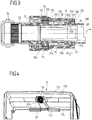
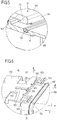
- the engagement elements 155 run in the form of obliquely extended tabs on the Entsperr comprise 111 so that the fingers 151 of each locking plate 15 raised in a vertical direction H and thus out of engagement with the counter-latching elements 301 on the part of the mating connector part 3 are brought.
- the locking between the connector part 1 and the mating connector part 3 is released, so that by further pulling on the actuating element 11, the connector part 1 can be removed from the mating connector part 3.
- the spring elements 16 hold the actuating element 11 in its currently occupied, non-actuated position. This is done under elastic preload.
- a sealing element 102 is arranged in the form of a circumferential sealing ring, which produces a sealing transition between the plug portion 100 on the part of the connector part 1 and the plug portion 30 on the part of the mating connector part 3 when plugged into the mating connector part 3 connector part.
- each latching plate 15 has two fingers 151, which are separated from each other by a central slot 152, the elasticity of the locking plate 15, for example, made of a spring steel is improved.
- each finger 151 has a latching element 151 and an engagement element 155, upon actuation of the actuating element 11, each finger 151 is actuated by itself, with elastic deformation of the latching plate 15.
- each locking element 153 has a bent edge 154, which can serve as an end stop for the actuating element 11, for example.
- the front edge 114 of the actuating element 11 can come into contact with the edges 154, so that the actuating element 11 can not be actuated further in the pulling direction Z.
- the locking elements 153 relative to the engagement elements 155 an enlarged lever arm (measured from the fixed to the housing part 10 surface portion 150), which causes a comparatively small stroke on the engagement elements 155 to a larger stroke on the locking elements 153, in particular the detent openings the locking elements 153 leads.
- the counter-locking elements 301 on the part of the mating connector part 3 can thus be formed with a greater height, so that an improved engagement between the locking elements 153 of the latching plate 15 and the associated counter-latching elements 301 of the mating connector part 3 can be created.
- unlocking elements 111 of the actuating element 11 are preferably not in engagement with the engagement elements 155 in the non-actuated position of the actuating element 11, so that small movements on the actuating element 11 do not lead to release of the latching, for example as a result of vibrations.
- each latching plate 15 can be positively mated with the latching elements 301 on the respective associated Surface of the plug portion 30 of the mating connector part 3 rest without the actuator 11 prevents this.
Landscapes
- Details Of Connecting Devices For Male And Female Coupling (AREA)
Priority Applications (1)
| Application Number | Priority Date | Filing Date | Title |
|---|---|---|---|
| PL17197142T PL3312944T3 (pl) | 2016-10-20 | 2017-10-18 | Część typu push-pull złącza wtykowego z blaszką zatrzaskową |
Applications Claiming Priority (1)
| Application Number | Priority Date | Filing Date | Title |
|---|---|---|---|
| LU93269A LU93269B1 (de) | 2016-10-20 | 2016-10-20 | Push-Pull-Steckverbinderteil mit einem Rastblech |
Publications (2)
| Publication Number | Publication Date |
|---|---|
| EP3312944A1 true EP3312944A1 (fr) | 2018-04-25 |
| EP3312944B1 EP3312944B1 (fr) | 2020-07-08 |
Family
ID=57517950
Family Applications (1)
| Application Number | Title | Priority Date | Filing Date |
|---|---|---|---|
| EP17197142.7A Active EP3312944B1 (fr) | 2016-10-20 | 2017-10-18 | Partie connecteur accouplable push-pull dotée d'une tôle d'arrêt |
Country Status (5)
| Country | Link |
|---|---|
| EP (1) | EP3312944B1 (fr) |
| ES (1) | ES2821778T3 (fr) |
| LU (1) | LU93269B1 (fr) |
| PL (1) | PL3312944T3 (fr) |
| PT (1) | PT3312944T (fr) |
Cited By (3)
| Publication number | Priority date | Publication date | Assignee | Title |
|---|---|---|---|---|
| DE102020000359A1 (de) | 2020-01-21 | 2021-07-22 | Yamaichi Electronics Deutschland Gmbh | Steckverbinder, insbesondere Push-Pull-Verbinder, zum Verbinden mit einer Steckverbinderbuchse, Steckverbindersystem und Verwendung eines Steckverbinders |
| WO2022258108A1 (fr) * | 2021-06-10 | 2022-12-15 | Harting Electric Stiftung & Co. Kg | Dispositif de verrouillage pour connecteurs de lignes |
| CN115986499A (zh) * | 2022-12-27 | 2023-04-18 | 宣城立讯精密工业有限公司 | 一种电连接器 |
Citations (7)
| Publication number | Priority date | Publication date | Assignee | Title |
|---|---|---|---|---|
| US5634809A (en) * | 1995-08-21 | 1997-06-03 | Honda Tsushin Kogyo Kabushiki Kaisha Tsushin Kogyo Co. Ltd. | Connector with lock mechanism |
| EP1341268A2 (fr) * | 2002-02-28 | 2003-09-03 | Japan Aviation Electronics Industry, Limited | Connecteur à mécanisme d'engagement |
| DE102005025769B3 (de) * | 2005-06-04 | 2006-09-21 | Harting Electric Gmbh & Co. Kg | Verriegelungseinrichtung für Steckverbinder |
| EP1744408A1 (fr) * | 2005-07-13 | 2007-01-17 | Neutrik Aktiengesellschaft | Connexion enfichable électrique |
| DE102013113631B3 (de) * | 2013-12-06 | 2015-04-23 | HARTING Electronics GmbH | Steckverbinder mit Steckkraftbegrenzung |
| US20150229075A1 (en) * | 2014-02-07 | 2015-08-13 | Wieson Technologies Co., Ltd. | Electrical plug connector |
| EP2978079A1 (fr) * | 2014-07-23 | 2016-01-27 | Multi-Holding AG | Couplage |
-
2016
- 2016-10-20 LU LU93269A patent/LU93269B1/de active IP Right Grant
-
2017
- 2017-10-18 EP EP17197142.7A patent/EP3312944B1/fr active Active
- 2017-10-18 PT PT171971427T patent/PT3312944T/pt unknown
- 2017-10-18 ES ES17197142T patent/ES2821778T3/es active Active
- 2017-10-18 PL PL17197142T patent/PL3312944T3/pl unknown
Patent Citations (7)
| Publication number | Priority date | Publication date | Assignee | Title |
|---|---|---|---|---|
| US5634809A (en) * | 1995-08-21 | 1997-06-03 | Honda Tsushin Kogyo Kabushiki Kaisha Tsushin Kogyo Co. Ltd. | Connector with lock mechanism |
| EP1341268A2 (fr) * | 2002-02-28 | 2003-09-03 | Japan Aviation Electronics Industry, Limited | Connecteur à mécanisme d'engagement |
| DE102005025769B3 (de) * | 2005-06-04 | 2006-09-21 | Harting Electric Gmbh & Co. Kg | Verriegelungseinrichtung für Steckverbinder |
| EP1744408A1 (fr) * | 2005-07-13 | 2007-01-17 | Neutrik Aktiengesellschaft | Connexion enfichable électrique |
| DE102013113631B3 (de) * | 2013-12-06 | 2015-04-23 | HARTING Electronics GmbH | Steckverbinder mit Steckkraftbegrenzung |
| US20150229075A1 (en) * | 2014-02-07 | 2015-08-13 | Wieson Technologies Co., Ltd. | Electrical plug connector |
| EP2978079A1 (fr) * | 2014-07-23 | 2016-01-27 | Multi-Holding AG | Couplage |
Cited By (4)
| Publication number | Priority date | Publication date | Assignee | Title |
|---|---|---|---|---|
| DE102020000359A1 (de) | 2020-01-21 | 2021-07-22 | Yamaichi Electronics Deutschland Gmbh | Steckverbinder, insbesondere Push-Pull-Verbinder, zum Verbinden mit einer Steckverbinderbuchse, Steckverbindersystem und Verwendung eines Steckverbinders |
| DE102020000359B4 (de) | 2020-01-21 | 2024-03-28 | Yamaichi Electronics Deutschland Gmbh | Steckverbinder, insbesondere Push-Pull-Verbinder, zum Verbinden mit einer Steckverbinderbuchse, Steckverbindersystem und Verwendung eines Steckverbinders |
| WO2022258108A1 (fr) * | 2021-06-10 | 2022-12-15 | Harting Electric Stiftung & Co. Kg | Dispositif de verrouillage pour connecteurs de lignes |
| CN115986499A (zh) * | 2022-12-27 | 2023-04-18 | 宣城立讯精密工业有限公司 | 一种电连接器 |
Also Published As
| Publication number | Publication date |
|---|---|
| EP3312944B1 (fr) | 2020-07-08 |
| PT3312944T (pt) | 2020-09-29 |
| ES2821778T3 (es) | 2021-04-27 |
| PL3312944T3 (pl) | 2020-12-28 |
| LU93269B1 (de) | 2018-05-30 |
Similar Documents
| Publication | Publication Date | Title |
|---|---|---|
| DE102010063576B4 (de) | Elektrischer Verbinder | |
| DE102009059685A1 (de) | Steckerelement mit einem Verriegelungsmechanismus | |
| DE112018004678T5 (de) | Stecker | |
| DE102016102071B3 (de) | Elektrische Steckverbinderanordnung und Löseelement hierzu | |
| DE102017117459A1 (de) | Anschlusseinrichtung zum Anschließen einer elektrischen Leitung | |
| DE202019101806U1 (de) | Elektrische Steckverbinderanordnung und Halteelement hierzu | |
| DE102017118014B3 (de) | Steckverbinderteil mit einem Verriegelungselement | |
| EP3312944B1 (fr) | Partie connecteur accouplable push-pull dotée d'une tôle d'arrêt | |
| DE602005000836T2 (de) | Elektrischer Steckverbinder | |
| DE102019213141A1 (de) | Elektronische einheit | |
| EP1936755B1 (fr) | Connecteur comportant une prise et une douille avec un support de contacts et une collerette de protection | |
| EP2689496B1 (fr) | Élément d'enfichage direct, en particulier pour appareils de commande de véhicule | |
| EP3766130B1 (fr) | Élément de contact pourvu d'un corps de contact et d'un élément élastique agencé contre ce dernier | |
| DE102018106185A1 (de) | Kontaktelement mit einem Kontaktkörper und einem daran angeordneten Federelement | |
| EP2854230B1 (fr) | Connecteur à fiches doté de verrouillage primaire et secondaire | |
| DE102021107646A1 (de) | Steckverbinder mit aufsteckbarem Verriegelungselement | |
| BE1026334B1 (de) | Steckverbinderbaugruppe mit akustischem Feedback | |
| DE102004002850B4 (de) | Elektrischer Steckverbinder | |
| LU102725B1 (de) | Steckverbinder mit aufsteckbarem Verriegelungselement | |
| LU500296B1 (de) | Variabel positionierbare Rastlasche und Steckverbinder | |
| DE202019105676U1 (de) | Elektrische Steckverbindung und Verriegelungselement | |
| DE202023104036U1 (de) | Sperrelement, Anordnung mit einem Steckverbinder und einem Sperrelement sowie Set aus einem Steckverbinder und einem Sperrelement | |
| DE102022213591A1 (de) | Steckverbinder, Steckverbinderanordnung und Verfahren zum Herstellen einer Steckverbindung | |
| DE102017115865A1 (de) | Anschlusseinrichtung zum Anschließen einer elektrischen Leitung | |
| DE202024105011U1 (de) | Montageplatte und damit gebildetes Set und Vorrichtung |
Legal Events
| Date | Code | Title | Description |
|---|---|---|---|
| PUAI | Public reference made under article 153(3) epc to a published international application that has entered the european phase |
Free format text: ORIGINAL CODE: 0009012 |
|
| STAA | Information on the status of an ep patent application or granted ep patent |
Free format text: STATUS: REQUEST FOR EXAMINATION WAS MADE |
|
| 17P | Request for examination filed |
Effective date: 20171018 |
|
| AK | Designated contracting states |
Kind code of ref document: A1 Designated state(s): AL AT BE BG CH CY CZ DE DK EE ES FI FR GB GR HR HU IE IS IT LI LT LU LV MC MK MT NL NO PL PT RO RS SE SI SK SM TR |
|
| AX | Request for extension of the european patent |
Extension state: BA ME |
|
| STAA | Information on the status of an ep patent application or granted ep patent |
Free format text: STATUS: EXAMINATION IS IN PROGRESS |
|
| 17Q | First examination report despatched |
Effective date: 20180518 |
|
| RBV | Designated contracting states (corrected) |
Designated state(s): AL AT BE BG CH CY CZ DE DK EE ES FI FR GB GR HR HU IE IS IT LI LT LU LV MC MK MT NL NO PL PT RO RS SE SI SK SM TR |
|
| GRAP | Despatch of communication of intention to grant a patent |
Free format text: ORIGINAL CODE: EPIDOSNIGR1 |
|
| STAA | Information on the status of an ep patent application or granted ep patent |
Free format text: STATUS: GRANT OF PATENT IS INTENDED |
|
| INTG | Intention to grant announced |
Effective date: 20200217 |
|
| GRAS | Grant fee paid |
Free format text: ORIGINAL CODE: EPIDOSNIGR3 |
|
| GRAA | (expected) grant |
Free format text: ORIGINAL CODE: 0009210 |
|
| STAA | Information on the status of an ep patent application or granted ep patent |
Free format text: STATUS: THE PATENT HAS BEEN GRANTED |
|
| AK | Designated contracting states |
Kind code of ref document: B1 Designated state(s): AL AT BE BG CH CY CZ DE DK EE ES FI FR GB GR HR HU IE IS IT LI LT LU LV MC MK MT NL NO PL PT RO RS SE SI SK SM TR |
|
| REG | Reference to a national code |
Ref country code: CH Ref legal event code: EP Ref country code: AT Ref legal event code: REF Ref document number: 1289469 Country of ref document: AT Kind code of ref document: T Effective date: 20200715 |
|
| REG | Reference to a national code |
Ref country code: DE Ref legal event code: R096 Ref document number: 502017006063 Country of ref document: DE |
|
| REG | Reference to a national code |
Ref country code: IE Ref legal event code: FG4D Free format text: LANGUAGE OF EP DOCUMENT: GERMAN |
|
| REG | Reference to a national code |
Ref country code: PT Ref legal event code: SC4A Ref document number: 3312944 Country of ref document: PT Date of ref document: 20200929 Kind code of ref document: T Free format text: AVAILABILITY OF NATIONAL TRANSLATION Effective date: 20200922 |
|
| REG | Reference to a national code |
Ref country code: LT Ref legal event code: MG4D |
|
| REG | Reference to a national code |
Ref country code: NL Ref legal event code: MP Effective date: 20200708 |
|
| PG25 | Lapsed in a contracting state [announced via postgrant information from national office to epo] |
Ref country code: FI Free format text: LAPSE BECAUSE OF FAILURE TO SUBMIT A TRANSLATION OF THE DESCRIPTION OR TO PAY THE FEE WITHIN THE PRESCRIBED TIME-LIMIT Effective date: 20200708 Ref country code: LT Free format text: LAPSE BECAUSE OF FAILURE TO SUBMIT A TRANSLATION OF THE DESCRIPTION OR TO PAY THE FEE WITHIN THE PRESCRIBED TIME-LIMIT Effective date: 20200708 Ref country code: SE Free format text: LAPSE BECAUSE OF FAILURE TO SUBMIT A TRANSLATION OF THE DESCRIPTION OR TO PAY THE FEE WITHIN THE PRESCRIBED TIME-LIMIT Effective date: 20200708 Ref country code: HR Free format text: LAPSE BECAUSE OF FAILURE TO SUBMIT A TRANSLATION OF THE DESCRIPTION OR TO PAY THE FEE WITHIN THE PRESCRIBED TIME-LIMIT Effective date: 20200708 Ref country code: GR Free format text: LAPSE BECAUSE OF FAILURE TO SUBMIT A TRANSLATION OF THE DESCRIPTION OR TO PAY THE FEE WITHIN THE PRESCRIBED TIME-LIMIT Effective date: 20201009 Ref country code: NO Free format text: LAPSE BECAUSE OF FAILURE TO SUBMIT A TRANSLATION OF THE DESCRIPTION OR TO PAY THE FEE WITHIN THE PRESCRIBED TIME-LIMIT Effective date: 20201008 Ref country code: BG Free format text: LAPSE BECAUSE OF FAILURE TO SUBMIT A TRANSLATION OF THE DESCRIPTION OR TO PAY THE FEE WITHIN THE PRESCRIBED TIME-LIMIT Effective date: 20201008 |
|
| PG25 | Lapsed in a contracting state [announced via postgrant information from national office to epo] |
Ref country code: RS Free format text: LAPSE BECAUSE OF FAILURE TO SUBMIT A TRANSLATION OF THE DESCRIPTION OR TO PAY THE FEE WITHIN THE PRESCRIBED TIME-LIMIT Effective date: 20200708 Ref country code: LV Free format text: LAPSE BECAUSE OF FAILURE TO SUBMIT A TRANSLATION OF THE DESCRIPTION OR TO PAY THE FEE WITHIN THE PRESCRIBED TIME-LIMIT Effective date: 20200708 Ref country code: IS Free format text: LAPSE BECAUSE OF FAILURE TO SUBMIT A TRANSLATION OF THE DESCRIPTION OR TO PAY THE FEE WITHIN THE PRESCRIBED TIME-LIMIT Effective date: 20201108 |
|
| PG25 | Lapsed in a contracting state [announced via postgrant information from national office to epo] |
Ref country code: NL Free format text: LAPSE BECAUSE OF FAILURE TO SUBMIT A TRANSLATION OF THE DESCRIPTION OR TO PAY THE FEE WITHIN THE PRESCRIBED TIME-LIMIT Effective date: 20200708 |
|
| REG | Reference to a national code |
Ref country code: DE Ref legal event code: R097 Ref document number: 502017006063 Country of ref document: DE |
|
| REG | Reference to a national code |
Ref country code: ES Ref legal event code: FG2A Ref document number: 2821778 Country of ref document: ES Kind code of ref document: T3 Effective date: 20210427 |
|
| PG25 | Lapsed in a contracting state [announced via postgrant information from national office to epo] |
Ref country code: IT Free format text: LAPSE BECAUSE OF FAILURE TO SUBMIT A TRANSLATION OF THE DESCRIPTION OR TO PAY THE FEE WITHIN THE PRESCRIBED TIME-LIMIT Effective date: 20200708 Ref country code: EE Free format text: LAPSE BECAUSE OF FAILURE TO SUBMIT A TRANSLATION OF THE DESCRIPTION OR TO PAY THE FEE WITHIN THE PRESCRIBED TIME-LIMIT Effective date: 20200708 Ref country code: SM Free format text: LAPSE BECAUSE OF FAILURE TO SUBMIT A TRANSLATION OF THE DESCRIPTION OR TO PAY THE FEE WITHIN THE PRESCRIBED TIME-LIMIT Effective date: 20200708 Ref country code: RO Free format text: LAPSE BECAUSE OF FAILURE TO SUBMIT A TRANSLATION OF THE DESCRIPTION OR TO PAY THE FEE WITHIN THE PRESCRIBED TIME-LIMIT Effective date: 20200708 Ref country code: DK Free format text: LAPSE BECAUSE OF FAILURE TO SUBMIT A TRANSLATION OF THE DESCRIPTION OR TO PAY THE FEE WITHIN THE PRESCRIBED TIME-LIMIT Effective date: 20200708 |
|
| PLBE | No opposition filed within time limit |
Free format text: ORIGINAL CODE: 0009261 |
|
| STAA | Information on the status of an ep patent application or granted ep patent |
Free format text: STATUS: NO OPPOSITION FILED WITHIN TIME LIMIT |
|
| PG25 | Lapsed in a contracting state [announced via postgrant information from national office to epo] |
Ref country code: AL Free format text: LAPSE BECAUSE OF FAILURE TO SUBMIT A TRANSLATION OF THE DESCRIPTION OR TO PAY THE FEE WITHIN THE PRESCRIBED TIME-LIMIT Effective date: 20200708 |
|
| REG | Reference to a national code |
Ref country code: CH Ref legal event code: PL |
|
| 26N | No opposition filed |
Effective date: 20210409 |
|
| PG25 | Lapsed in a contracting state [announced via postgrant information from national office to epo] |
Ref country code: SK Free format text: LAPSE BECAUSE OF FAILURE TO SUBMIT A TRANSLATION OF THE DESCRIPTION OR TO PAY THE FEE WITHIN THE PRESCRIBED TIME-LIMIT Effective date: 20200708 Ref country code: LU Free format text: LAPSE BECAUSE OF NON-PAYMENT OF DUE FEES Effective date: 20201018 Ref country code: MC Free format text: LAPSE BECAUSE OF FAILURE TO SUBMIT A TRANSLATION OF THE DESCRIPTION OR TO PAY THE FEE WITHIN THE PRESCRIBED TIME-LIMIT Effective date: 20200708 |
|
| REG | Reference to a national code |
Ref country code: BE Ref legal event code: MM Effective date: 20201031 |
|
| PG25 | Lapsed in a contracting state [announced via postgrant information from national office to epo] |
Ref country code: FR Free format text: LAPSE BECAUSE OF NON-PAYMENT OF DUE FEES Effective date: 20201031 |
|
| PG25 | Lapsed in a contracting state [announced via postgrant information from national office to epo] |
Ref country code: LI Free format text: LAPSE BECAUSE OF NON-PAYMENT OF DUE FEES Effective date: 20201031 Ref country code: SI Free format text: LAPSE BECAUSE OF FAILURE TO SUBMIT A TRANSLATION OF THE DESCRIPTION OR TO PAY THE FEE WITHIN THE PRESCRIBED TIME-LIMIT Effective date: 20200708 Ref country code: CH Free format text: LAPSE BECAUSE OF NON-PAYMENT OF DUE FEES Effective date: 20201031 Ref country code: BE Free format text: LAPSE BECAUSE OF NON-PAYMENT OF DUE FEES Effective date: 20201031 |
|
| PG25 | Lapsed in a contracting state [announced via postgrant information from national office to epo] |
Ref country code: IE Free format text: LAPSE BECAUSE OF NON-PAYMENT OF DUE FEES Effective date: 20201018 |
|
| PG25 | Lapsed in a contracting state [announced via postgrant information from national office to epo] |
Ref country code: TR Free format text: LAPSE BECAUSE OF FAILURE TO SUBMIT A TRANSLATION OF THE DESCRIPTION OR TO PAY THE FEE WITHIN THE PRESCRIBED TIME-LIMIT Effective date: 20200708 Ref country code: MT Free format text: LAPSE BECAUSE OF FAILURE TO SUBMIT A TRANSLATION OF THE DESCRIPTION OR TO PAY THE FEE WITHIN THE PRESCRIBED TIME-LIMIT Effective date: 20200708 Ref country code: CY Free format text: LAPSE BECAUSE OF FAILURE TO SUBMIT A TRANSLATION OF THE DESCRIPTION OR TO PAY THE FEE WITHIN THE PRESCRIBED TIME-LIMIT Effective date: 20200708 |
|
| GBPC | Gb: european patent ceased through non-payment of renewal fee |
Effective date: 20211018 |
|
| PG25 | Lapsed in a contracting state [announced via postgrant information from national office to epo] |
Ref country code: MK Free format text: LAPSE BECAUSE OF FAILURE TO SUBMIT A TRANSLATION OF THE DESCRIPTION OR TO PAY THE FEE WITHIN THE PRESCRIBED TIME-LIMIT Effective date: 20200708 |
|
| PG25 | Lapsed in a contracting state [announced via postgrant information from national office to epo] |
Ref country code: GB Free format text: LAPSE BECAUSE OF NON-PAYMENT OF DUE FEES Effective date: 20211018 |
|
| PGFP | Annual fee paid to national office [announced via postgrant information from national office to epo] |
Ref country code: PT Payment date: 20221004 Year of fee payment: 6 |
|
| PGFP | Annual fee paid to national office [announced via postgrant information from national office to epo] |
Ref country code: PL Payment date: 20221017 Year of fee payment: 6 |
|
| P01 | Opt-out of the competence of the unified patent court (upc) registered |
Effective date: 20230424 |
|
| PG25 | Lapsed in a contracting state [announced via postgrant information from national office to epo] |
Ref country code: PT Free format text: LAPSE BECAUSE OF NON-PAYMENT OF DUE FEES Effective date: 20240418 |
|
| PG25 | Lapsed in a contracting state [announced via postgrant information from national office to epo] |
Ref country code: PT Free format text: LAPSE BECAUSE OF NON-PAYMENT OF DUE FEES Effective date: 20240418 |
|
| PGFP | Annual fee paid to national office [announced via postgrant information from national office to epo] |
Ref country code: AT Payment date: 20241018 Year of fee payment: 8 |
|
| PGFP | Annual fee paid to national office [announced via postgrant information from national office to epo] |
Ref country code: CZ Payment date: 20241014 Year of fee payment: 8 |
|
| PG25 | Lapsed in a contracting state [announced via postgrant information from national office to epo] |
Ref country code: PL Free format text: LAPSE BECAUSE OF NON-PAYMENT OF DUE FEES Effective date: 20231018 |
|
| PGFP | Annual fee paid to national office [announced via postgrant information from national office to epo] |
Ref country code: ES Payment date: 20251118 Year of fee payment: 9 |
|
| PGFP | Annual fee paid to national office [announced via postgrant information from national office to epo] |
Ref country code: DE Payment date: 20251229 Year of fee payment: 9 |