EP3312954A1 - Bougie d'allumage - Google Patents
Bougie d'allumage Download PDFInfo
- Publication number
- EP3312954A1 EP3312954A1 EP16813904.6A EP16813904A EP3312954A1 EP 3312954 A1 EP3312954 A1 EP 3312954A1 EP 16813904 A EP16813904 A EP 16813904A EP 3312954 A1 EP3312954 A1 EP 3312954A1
- Authority
- EP
- European Patent Office
- Prior art keywords
- diameter portion
- resistor
- center electrode
- spark plug
- large diameter
- Prior art date
- Legal status (The legal status is an assumption and is not a legal conclusion. Google has not performed a legal analysis and makes no representation as to the accuracy of the status listed.)
- Granted
Links
Images


Classifications
-
- H—ELECTRICITY
- H01—ELECTRIC ELEMENTS
- H01T—SPARK GAPS; OVERVOLTAGE ARRESTERS USING SPARK GAPS; SPARKING PLUGS; CORONA DEVICES; GENERATING IONS TO BE INTRODUCED INTO NON-ENCLOSED GASES
- H01T13/00—Sparking plugs
- H01T13/20—Sparking plugs characterised by features of the electrodes or insulation
- H01T13/34—Sparking plugs characterised by features of the electrodes or insulation characterised by the mounting of electrodes in insulation, e.g. by embedding
-
- H—ELECTRICITY
- H01—ELECTRIC ELEMENTS
- H01T—SPARK GAPS; OVERVOLTAGE ARRESTERS USING SPARK GAPS; SPARKING PLUGS; CORONA DEVICES; GENERATING IONS TO BE INTRODUCED INTO NON-ENCLOSED GASES
- H01T13/00—Sparking plugs
- H01T13/20—Sparking plugs characterised by features of the electrodes or insulation
-
- H—ELECTRICITY
- H01—ELECTRIC ELEMENTS
- H01T—SPARK GAPS; OVERVOLTAGE ARRESTERS USING SPARK GAPS; SPARKING PLUGS; CORONA DEVICES; GENERATING IONS TO BE INTRODUCED INTO NON-ENCLOSED GASES
- H01T13/00—Sparking plugs
- H01T13/20—Sparking plugs characterised by features of the electrodes or insulation
- H01T13/32—Sparking plugs characterised by features of the electrodes or insulation characterised by features of the earthed electrode
-
- H—ELECTRICITY
- H01—ELECTRIC ELEMENTS
- H01T—SPARK GAPS; OVERVOLTAGE ARRESTERS USING SPARK GAPS; SPARKING PLUGS; CORONA DEVICES; GENERATING IONS TO BE INTRODUCED INTO NON-ENCLOSED GASES
- H01T13/00—Sparking plugs
- H01T13/40—Sparking plugs structurally combined with other devices
- H01T13/41—Sparking plugs structurally combined with other devices with interference suppressing or shielding means
Definitions
- the present invention relates to a spark plug.
- a spark plug is a component which generates spark discharge in order to ignite an air-fuel mixture inside a combustion chamber.
- a structure of the spark plug there is known a structure which includes an insulator internally having an axial hole extending along an axis of the insulator, a metallic shell for internally holding the insulator, a center electrode held inside the axial hole, and an electrically conductive seal for holding the center electrode inside the axial hole (refer to Patent Document 1).
- the center electrode includes a flange portion which bulges in a radial direction, and a head portion which protrudes rearward from the flange portion. This structure is utilized so as to hold the center electrode in the insulator.
- the flange portion is brought into contact with a step portion provided in the axial hole, thereby restraining forward movement of the center electrode. Furthermore, a space around the head portion and the flange portion is filled with a seal so as to ensure the impact resistance of the center electrode. In this manner, even if the center electrode receives an impact due to the combustion, the center electrode is less likely to loosen.
- Patent Document 1 International Publication No. WO2012/105255
- the spark plug needs to have electrode durability against repeated spark discharge.
- An effective way to improve this durability is to reduce the capacitance between the metallic shell and a conductor disposed inside the insulator.
- This conductor is the seal or the center electrode.
- the capacitance can be reduced by, for example, shortening the head portion and lowering the height of the seal in the axial direction in the same amount as the head portion is shortened.
- the head portion is shortened, the holding power of the seal is weakened. Consequently, the impact resistance of the center electrode decreases, and the center electrode is likely to loosen.
- the present invention aims to simultaneously realize reduction of capacitance and securing of the impact resistance of a center electrode.
- the present invention has been accomplished in order to solve the above-described problems, and can be realized in the following modes.
- the present invention can be realized in various modes in addition to the above-described modes.
- the present invention can be realized as a method of manufacturing the spark plug.
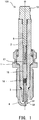
- FIG. 1 is a sectional view illustrating a spark plug 101.
- the spark plug 101 has a metallic shell 1, an insulator 2, a center electrode 3, a ground electrode 4, and a metallic terminal 13.
- the longitudinal axis of the spark plug 101 is represented by an axial line O.
- the ground electrode 4 side along the axial line O is referred to as a forward side of the spark plug 101
- the metallic terminal 13 side along the axial line O is referred to as a rear side.
- the metallic shell 1 is formed of metal such as carbon steel in a hollow cylindrical shape and constitutes a housing of the spark plug 101.
- the insulator 2 is formed of a ceramic sintered body, and its forward end portion is accommodated inside the metallic shell 1.
- the insulator 2 is a tubular member and has an axial hole 6 formed therein along the axial line O. A portion of the metallic terminal 13 is inserted into and fixed to one end of the axial hole 6, and the center electrode 3 is inserted into and fixed to the other end of the axial hole 6.
- the resistor 15 is disposed between the metallic terminal 13 and the center electrode 3. Opposite end portions of the resistor 15 are electrically connected to the center electrode 3 and the metallic terminal 13, respectively, via an electrically conductive glass seal layer 16 and a metallic terminal-side conductive glass seal layer 17, respectively.
- the resistor 15 functions as an electrical resistor between the metallic terminal 13 and the center electrode 3, thereby restraining generation of radio noise (noise) during spark discharge.
- the resistor 15 is formed of ceramic powder, an electrically conductive material, glass, and a binder (adhesive). In the present embodiment, the resistor 15 is manufactured through a manufacturing procedure described later.
- the center electrode 3 has an ignition portion 31 formed at the forward end, and is disposed in the axial hole 6 in a state where the ignition portion 31 is exposed.
- the ground electrode 4 is welded at one end to the metallic shell 1. A portion of the ground electrode 4 at the other end is laterally bent such that a distal end portion 32 of the ground electrode 4 faces the ignition portion 31 of the center electrode 3 while leaving a gap therebetween.
- a thread 5 is formed on the outer periphery of the metallic shell 1 of the spark plug 101 having the above-described configuration.
- the spark plug 101 is mounted on a cylinder head of an engine by using the thread 5.
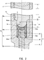
- FIG. 2 is an enlarged sectional view illustrating the electrically conductive glass seal layer 16 and its vicinity.
- the axial hole 6 includes a large diameter portion 6w, an intermediate diameter portion 6m, and a small diameter portion 6n.
- the large diameter portion 6w has an inner diameter larger than that of the intermediate diameter portion 6m.
- the intermediate diameter portion 6m has an inner diameter larger than that of the small diameter portion 6n.
- the intermediate diameter portion 6m has a step portion 6s and is connected to the rear end of the small diameter portion 6n via the step portion 6s.
- Each of the large diameter portion 6w and the small diameter portion 6n has an approximately ideal cylindrical inner circumferential surface.
- the inner circumferential surfaces of the large diameter portion 6w and the small diameter portion 6n may be inclined due to die removal during manufacturing.
- the boundary between the large diameter portion 6w and the intermediate diameter portion 6m is a position where the diameter starts to decrease beyond the degree of decrease in the diameter due to the above-described inclination.
- the position is represented by a boundary Bwm shown in FIG. 2 .
- the decrease in the diameter means that the diameter decreases from the rear side toward the forward side.
- the step portion 6s has a conical surface of an approximately ideal truncated cone.
- the rear end of the step portion 6s is a position where an increase in the diameter due to the conical surface stops.
- the position is represented by a boundary Bms shown in FIG. 2 .
- the increase in the diameter means that the diameter increases from the forward side toward the rear side.
- the large diameter portion 6w has an inner diameter larger than that of the intermediate diameter portion 6m
- the above description of "the large diameter portion 6w has an inner diameter larger than that of the intermediate diameter portion 6m” may be paraphrased into any one of the following. 1. "The average inner diameter of the large diameter portion 6w is larger than the average inner diameter of the intermediate diameter portion 6m.” 2. “The minimum value of the inner diameter of the large diameter portion 6w is greater than the maximum value of the inner diameter of the intermediate diameter portion 6m in a region where the wall surface of the intermediate diameter portion 6m is in contact with the electrically conductive glass seal layer 16.” 3.
- the minimum value of the inner diameter of the large diameter portion 6w is equal to or smaller than the maximum value of the inner diameter of the intermediate diameter portion 6m.
- the reason for describing "equal to or smaller than” in the above-described item 3 is that both the minimum value of the inner diameter of the large diameter portion 6w and the maximum value of the inner diameter of the intermediate diameter portion 6m are their values obtained at the boundary Bwm and both the values coincide with each other.
- the intermediate diameter portion 6m can also be regarded as a portion which connects the large diameter portion 6w and the small diameter portion 6n to each other.
- the inner diameter at the boundary Bwm is larger than the inner diameter at the boundary Bms. Accordingly, at least a portion of the intermediate diameter portion 6m is tapered such that its diameter decreases toward the forward end.
- the diameter decreases toward the forward end mainly in a region extending from the rear end of the step portion 6s to the forward end thereof and in a region extending from the boundary Bwm to a corner portion K.
- the center electrode 3 includes a flange portion 3F, a leg portion 3L, and a head portion 3H.
- the flange portion 3F extends in the radial direction inside the intermediate diameter portion 6m, and abuts against the step portion 6s.
- the leg portion 3L extends forward from the flange portion 3F and is disposed inside the small diameter portion 6n.
- the head portion 3H extends rearward from the flange portion 3F.
- the electrically conductive glass seal layer 16 is disposed inside the intermediate diameter portion 6m. That is, both the forward end and the rear end of the electrically conductive glass seal layer 16 are located inside the intermediate diameter portion 6m. Accordingly, the electrically conductive glass seal layer 16 is not disposed in the large diameter portion 6w.
- the capacitance of a capacitor formed in a region extending from the forward end of the electrically conductive glass seal layer 16 to the rear end of the resistor 15 will be described.
- This capacitor is formed between the metallic shell 1 and a conductor (hereinafter, referred to as an internal conductor) disposed in the axial hole 6.
- the internal conductor in the present embodiment is the electrically conductive glass seal layer 16.
- the above-described capacitance is denoted by C with a number (1 or 2) indicating the embodiment added as a suffix.
- the capacitance is expressed as capacitance C1.
- L represents the length in the axial direction of the cylinder
- ⁇ represents a relative dielectric constant
- a represents the inner diameter of the cylinder
- b represents the outer diameter of the cylinder. Therefore, if the outer diameter b is constant, as the inner diameter a decreases, the capacitance C decreases.
- the large diameter portion 6wa illustrated in FIG. 2 indicates the large diameter portion present in a comparative example which does not include the intermediate diameter portion 6m.
- the step portion 6sa illustrated in FIG. 3 indicates the step portion present in the comparative example, which is a portion of the large diameter portion 6wa.
- the step portion 6sa in the comparative example is a portion of the large diameter portion 6wa and connects the large diameter portion 6wa and the small diameter portion 6n to each other.
- the electrically conductive glass seal layer 16 is charged so as to come into contact with the wall surface of the large diameter portion 6wa. Therefore, the outer diameter of the electrically conductive glass seal layer 16 which corresponds to the above-described inner diameter a increases, and the capacitance increases accordingly.
- the outer diameter of the electrically conductive glass seal layer 16 decreases. Therefore, the capacitance C1 also decreases.
- a distance Lm illustrated in FIG. 2 represents a distance from the forward-side end portion of the resistor 15 to the forward end of the large diameter portion 6w in the direction of the axial line O.
- a distance Lw illustrated in FIG. 2 represents a distance from the forward end of the large diameter portion 6w to the rear-side end portion of the resistor 15.
- a ratio of the distance Lm/the distance Lw (hereinafter, this ratio is referred to as a distance ratio) is set to 20%.
- a load life test was carried out under test conditions prescribed in 7.14 of JIS B8031: 2006 (Internal Combustion Engine - Spark Plug). Then, in order to evaluate one type of samples, ten samples having the same configuration were prepared and a test operation was performed for each sample for 100 hours. Then, of the ten samples, samples whose resistance change rates were less than 50% were determined to be acceptable, and samples whose resistance change rates were 50% or greater were determined to be unacceptable.
- the resistance is the electric resistance between the metallic terminal 13 and the center electrode 3 and was measured in accordance with 7.13 of JIS B8031: 2006.
- the resistance change rate is the ratio of the difference between the resistances before and after the test to the resistance before the test.
- test results showed that in the case of the sample type whose distance ratio was 10% or 20%, all ten samples were determined to be acceptable. In contrast, in the case of the sample type whose distance ratio was 25%, 30%, or 50%, all of the ten samples were determined to be unacceptable.
- the test was also carried out for the above-described comparative example, and the test results showed that all ten samples were acceptable.
- the distance Lm is preferably as short as possible. Therefore, a test was carried out in which the distance ratio was changed while the distance Lw was used as a reference. As described above, the samples were determined to acceptable if the distance ratio was 20% or smaller. Therefore, in the present embodiment, the distance ratio was set to 20%.
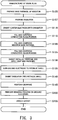
- FIG. 3 is a flowchart illustrating a procedure of manufacturing the spark plug. First, a base material of the resistor 15 is manufactured (S105).
- FIG. 4 is a flowchart illustrating a procedure of manufacturing the base material of the resistor 15.
- materials are mixed using a wet ball mill (S205). These materials are ceramic powder, an electrically conductive material, and a binder.
- the ceramic powder is ceramic powder containing ZrO 2 and TiO 2 .
- the electrically conductive material is carbon black.
- the binder organic binder
- Water serving as a solvent is added to these materials, and all are mixed and stirred using the wet ball mill. At that time, although the materials are mixed together, the degree of dispersion of the materials is relatively low.
- the mixed materials are dispersed using a high-speed shear mixer (S210).
- the high-speed shear mixer mixes the materials while greatly dispersing the materials by using a strong shearing force generated by blades (stirring blades).
- the high-speed shearing mixer is an axial mixer.
- the materials obtained in S210 are immediately granulated using a spray drying method (S215).
- Water and glass powder (coarse glass powder) are added to the powder obtained in S215, followed by mixing (S220) and drying (S225).
- S220 mixing glass powder
- S225 drying glass powder
- the base material (powder) of the resistor 15 is completed.
- a mixer used in the mixing in S220 described above a universal mixer can be used as a mixer used in the mixing in S220 described above.
- the insulator 2 is manufactured (S107). Specifically, first, the outer peripheral shape of the insulator 2 and the shape of the axial hole 6 including the large diameter portion 6w, the intermediate diameter portion 6m, and the small diameter portion 6n are formed by means of molding. Thereafter, the wall surface of the axial hole 6 may be finished by means of cutting.
- the center electrode 3 is inserted into the axial hole 6 of the insulator 2 (S110).
- the axial hole 6 is filled with the electrically conductive glass powder, and the conductive glass powder is compressed (S115).
- this compression is realized in such a way that a bar-shaped jig is inserted into the axial hole 6 so as to press the electrically conductive glass powder filling the axial hole 6.
- a layer of the electrically conductive glass powder formed in S115 is subjected to a heat compression process (to be described later), thereby forming the electrically conductive glass seal layer 16.
- the electrically conductive glass powder is obtained by mixing copper powder and calcium borosilicate glass powder.
- the axial hole 6 is filled with the base material (powder) of the resistor 15, and the base material is compressed (S120).
- the axial hole 6 is further filled with the electrically conductive glass powder, and the conductive glass powder is compressed (S125).
- the powder layer formed in S120 is subjected to the heat compression process (to be described later), thereby forming the resistor 15.
- the powder layer formed in S125 is subjected to the heat compression process (to be described later), thereby forming the metallic terminal-side conductive glass seal layer 17.
- the electrically conductive glass powder used in S125 is the same powder as the electrically conductive glass powder used in S115.
- the compression method used in S120 and S125 is the same method as the compression method used in S115.
- a portion of the metallic terminal 13 is inserted into the axial hole 6, and a predetermined pressure is applied thereto from the metallic terminal 13 side while the insulator 2 is entirely heated (S130). Through this heat compression process, the materials filling the axial hole 6 are compressed and fired. In this manner, the electrically conductive glass seal layer 16, the metallic terminal-side conductive glass seal layer 17, and the resistor 15 are formed inside the axial hole 6.
- the ground electrode is joined to the metallic shell 1 (S135), the insulator 2 is inserted into the metallic shell 1 (S140), and the metallic shell 1 is crimped (S145). As a result of the crimping in S145, the insulator 2 is fixed to the metallic shell 1. Next, the distal end of the ground electrode joined to the metallic shell 1 is subjected to a bending process (S150), whereby the ground electrode 4 is completed. Thereafter, a gasket (not illustrated) is attached to the metallic shell 1 (S155). Thus, the spark plug 101 is completed.
- Embodiment 2 a spark plug 102 of Embodiment 2 will be described.
- Embodiment 3 the structural features which are not specifically described are the same as those in Embodiment 1.
- the center electrode 3 has a protruding portion 3p located on the rear side of the rear end of the electrically conductive glass seal layer 16. Therefore, the protruding portion 3p is buried in the resistor 15.
- the surface of the protruding portion 3p contains a predetermined metal or a nickel alloy in the largest amount.
- the above-described predetermined metal is a metal whose main component is any one of zinc, tin, lead, rhodium, palladium, platinum, copper, gold, antimony, and silver.
- the above-described nickel alloy is a nickel brazing alloy and contains either boron or phosphorus.
- This type of nickel alloy or the above-described predetermined metal has a low melting point, and is softened at the temperature at which the filling powder is subjected to hot pressing. Therefore, the contact between the resistor 15 and the center electrode 3 is improved, whereby the state of the electrical connection between the resistor 15 and the center electrode 3 is improved.
- the center electrode 3 is manufactured using an iron-based material. Thereafter, the head portion 3H is coated by means of plating or the like.
- capacitance C2 will be described.
- the head portion 3H and the electrically conductive glass seal layer 16 serve as an internal conductor.
- Capacitance C3H is the capacitance of a capacitor in which the head portion 3H serves as the internal conductor, and the insulator 2 and the resistor 15 serve as the dielectric.
- Capacitance C16 is the capacitance of a capacitor in which the electrically conductive glass seal layer 16 serves as the internal conductor, and the insulator 2 serves as the dielectric.
- the capacitances C3H and C16 are connected in parallel. Accordingly, when both the capacitances C3H and C16 are added as described above, the result capacitance is equal to the capacitance C2 which is a composite value.
- the length of the capacitor corresponding to the capacitance C16 as measured in the direction of the axial line O is the length La, and is equal to the length La shown in FIG. 2 . Furthermore, other parameters are the same as those in Embodiment 1. Therefore, the capacitance of the capacitor formed in a region extending rearward from the forward end of the electrically conductive glass seal layer 16 to a position (hereinafter, referred to as a division position) corresponding to the length La has the same value in Embodiments 1 and 2 (capacitance C16 in Embodiment 2).
- the capacitance in a region located on the rear side of the division position differs between Embodiments 1 and 2.
- the capacitance is the capacitance C3H.
- the length of the capacitor corresponding to the capacitance C3H as measured in the direction of the axial line O is Lb2, and is shorter than Lb1 in the case of Embodiment 1.
- the inner diameter a corresponding to the capacitance C3H is the outer diameter of the head portion 3H, and is smaller than the inner diameter of the intermediate diameter portion 6m. Therefore, the capacitance on the rear side of the division position in Embodiment 2 is smaller than that in Embodiment 1. As a result, the capacitance C2 becomes smaller than the capacitance C1.
- the electrically conductive glass seal layer 16 is shortened as described above. In this manner, the durability of the center electrode 3 is ensured while the capacitance C2 is decreased. The durability of the center electrode 3 is ensured because the head portion 3H longer than the length of the electrically conductive glass seal layer 16 is buried in the resistor 15 and the electrically conductive glass seal layer 16.
- the distance Lm2 is the distance from the forward-side end portion of the center electrode 3 to the forward end of the large diameter portion 6w in the direction of the axial line O.
- the rear end of the center electrode 3 protrudes to the rear side in relation to the rear end of the resistor 15. Accordingly, current hardly flows through a portion of the resistor 15 located forward of the rear end of the center electrode 3, and thus, its electric load does not increase. Therefore, the durability of the resistor 15 can be further improved by shortening the length Lm and additionally, shortening the length Lm2, i.e., decreasing the second distance ratio.
- the rear-side end portion of the protruding portion 3p is disposed inside the large diameter portion 6w.
- the rear-side end portion of the head portion 3H is disposed inside the large diameter portion 6w.
- the rear-side end portion of the center electrode 3 is disposed inside the large diameter portion 6w.
- the expression "disposed inside the large diameter portion 6w" used in the above three sentences can be paraphrased as "located on the rear side of the boundary Bwm" or "located on the rear side of the rear end of the intermediate diameter portion 6m.”
- Embodiment 3 As in the case of Embodiment 2, in a region on the forward side of the rear end of the center electrode 3, current hardly flows through the resistor 15.
- the rear-side end portion of the center electrode 3 is disposed inside the large diameter portion 6w. Therefore, current hardly flows through a portion of the resistor 15 disposed inside the intermediate diameter portion 6m. As a result, it is possible to further improve the durability of the resistor 15 as compared with Embodiments 1 and 2.
- the distance ratio is also set to 20% (not illustrated).
- an electrically conductive substance other than copper powder may be used.
- glass powder other than calcium borosilicate glass powder may be used.
- carbon black or graphite powder may be used as the electrically conductive substance.
- the distance ratio may be set to any desired value of 20% or smaller.
- the distance ratio may exceed 20% and the second distance ratio may be set to 20% or smaller. Even in this case, it is conceivable that the load life can be ensured.
- the intermediate diameter portion 6m may have a tapered shape.
- the entire protruding portion 3p including the bulk thereof may be formed such that it contains the above-described predetermined metal or the nickel alloy in the largest amount.
- the surface of the protruding portion 3p can also be formed so as to contain the predetermined metal or the nickel alloy in the largest amount.
- the above-described nickel alloy may contain both boron and phosphorus.
Landscapes
- Chemical & Material Sciences (AREA)
- Engineering & Computer Science (AREA)
- Combustion & Propulsion (AREA)
- Spark Plugs (AREA)
Applications Claiming Priority (2)
| Application Number | Priority Date | Filing Date | Title |
|---|---|---|---|
| JP2015124317A JP6087991B2 (ja) | 2015-06-22 | 2015-06-22 | スパークプラグ |
| PCT/JP2016/002666 WO2016208128A1 (fr) | 2015-06-22 | 2016-06-02 | Bougie d'allumage |
Publications (3)
| Publication Number | Publication Date |
|---|---|
| EP3312954A1 true EP3312954A1 (fr) | 2018-04-25 |
| EP3312954A4 EP3312954A4 (fr) | 2019-03-06 |
| EP3312954B1 EP3312954B1 (fr) | 2019-11-27 |
Family
ID=57585427
Family Applications (1)
| Application Number | Title | Priority Date | Filing Date |
|---|---|---|---|
| EP16813904.6A Active EP3312954B1 (fr) | 2015-06-22 | 2016-06-02 | Bougie d'allumage |
Country Status (5)
| Country | Link |
|---|---|
| US (1) | US10084288B2 (fr) |
| EP (1) | EP3312954B1 (fr) |
| JP (1) | JP6087991B2 (fr) |
| CN (1) | CN107710532B (fr) |
| WO (1) | WO2016208128A1 (fr) |
Families Citing this family (2)
| Publication number | Priority date | Publication date | Assignee | Title |
|---|---|---|---|---|
| JP7255407B2 (ja) * | 2019-07-26 | 2023-04-11 | 株式会社デンソー | スパークプラグの製造方法 |
| JP7415766B2 (ja) * | 2020-04-17 | 2024-01-17 | 株式会社デンソー | スパークプラグ及びその製造方法 |
Family Cites Families (8)
| Publication number | Priority date | Publication date | Assignee | Title |
|---|---|---|---|---|
| JPS58189917A (ja) * | 1982-04-30 | 1983-11-05 | 日本特殊陶業株式会社 | 抵抗体入り点火栓 |
| US6191525B1 (en) * | 1997-08-27 | 2001-02-20 | Ngk Spark Plug Co., Ltd. | Spark plug |
| JPH11214119A (ja) | 1998-01-28 | 1999-08-06 | Ngk Spark Plug Co Ltd | 抵抗体入りスパークプラグ |
| US7443089B2 (en) * | 2006-06-16 | 2008-10-28 | Federal Mogul World Wide, Inc. | Spark plug with tapered fired-in suppressor seal |
| JP4948515B2 (ja) * | 2008-12-26 | 2012-06-06 | 日本特殊陶業株式会社 | プラズマジェット点火プラグ |
| KR101441836B1 (ko) * | 2010-10-01 | 2014-09-18 | 니혼도꾸슈도교 가부시키가이샤 | 스파크 플러그 |
| KR101515314B1 (ko) | 2011-02-02 | 2015-04-24 | 니혼도꾸슈도교 가부시키가이샤 | 스파크 플러그 |
| JP6248601B2 (ja) * | 2013-10-16 | 2017-12-20 | 株式会社デンソー | 内燃機関用スパークプラグ |
-
2015
- 2015-06-22 JP JP2015124317A patent/JP6087991B2/ja active Active
-
2016
- 2016-06-02 CN CN201680036803.XA patent/CN107710532B/zh active Active
- 2016-06-02 EP EP16813904.6A patent/EP3312954B1/fr active Active
- 2016-06-02 US US15/738,650 patent/US10084288B2/en active Active
- 2016-06-02 WO PCT/JP2016/002666 patent/WO2016208128A1/fr not_active Ceased
Also Published As
| Publication number | Publication date |
|---|---|
| JP2017010740A (ja) | 2017-01-12 |
| EP3312954B1 (fr) | 2019-11-27 |
| US20180183216A1 (en) | 2018-06-28 |
| CN107710532B (zh) | 2019-09-20 |
| US10084288B2 (en) | 2018-09-25 |
| EP3312954A4 (fr) | 2019-03-06 |
| JP6087991B2 (ja) | 2017-03-01 |
| WO2016208128A1 (fr) | 2016-12-29 |
| CN107710532A (zh) | 2018-02-16 |
Similar Documents
| Publication | Publication Date | Title |
|---|---|---|
| EP3312952B1 (fr) | Bougie d'allumage | |
| JP5414896B2 (ja) | スパークプラグ | |
| EP3041094B1 (fr) | Bougie d'allumage | |
| WO2011036871A1 (fr) | Bougie d'allumage | |
| EP3312954B1 (fr) | Bougie d'allumage | |
| EP3226366B1 (fr) | Bougie d'allumage | |
| US10256610B2 (en) | Spark plug | |
| EP3312953B1 (fr) | Bougie d'allumage | |
| US9711951B2 (en) | Spark plug | |
| JP6628767B2 (ja) | スパークプラグ | |
| US9843167B2 (en) | Spark plug |
Legal Events
| Date | Code | Title | Description |
|---|---|---|---|
| STAA | Information on the status of an ep patent application or granted ep patent |
Free format text: STATUS: THE INTERNATIONAL PUBLICATION HAS BEEN MADE |
|
| PUAI | Public reference made under article 153(3) epc to a published international application that has entered the european phase |
Free format text: ORIGINAL CODE: 0009012 |
|
| STAA | Information on the status of an ep patent application or granted ep patent |
Free format text: STATUS: REQUEST FOR EXAMINATION WAS MADE |
|
| 17P | Request for examination filed |
Effective date: 20171222 |
|
| AK | Designated contracting states |
Kind code of ref document: A1 Designated state(s): AL AT BE BG CH CY CZ DE DK EE ES FI FR GB GR HR HU IE IS IT LI LT LU LV MC MK MT NL NO PL PT RO RS SE SI SK SM TR |
|
| AX | Request for extension of the european patent |
Extension state: BA ME |
|
| DAV | Request for validation of the european patent (deleted) | ||
| DAX | Request for extension of the european patent (deleted) | ||
| A4 | Supplementary search report drawn up and despatched |
Effective date: 20190205 |
|
| RIC1 | Information provided on ipc code assigned before grant |
Ipc: H01T 13/34 20060101AFI20190130BHEP Ipc: H01T 13/20 20060101ALI20190130BHEP |
|
| GRAP | Despatch of communication of intention to grant a patent |
Free format text: ORIGINAL CODE: EPIDOSNIGR1 |
|
| STAA | Information on the status of an ep patent application or granted ep patent |
Free format text: STATUS: GRANT OF PATENT IS INTENDED |
|
| INTG | Intention to grant announced |
Effective date: 20190628 |
|
| GRAS | Grant fee paid |
Free format text: ORIGINAL CODE: EPIDOSNIGR3 |
|
| GRAA | (expected) grant |
Free format text: ORIGINAL CODE: 0009210 |
|
| STAA | Information on the status of an ep patent application or granted ep patent |
Free format text: STATUS: THE PATENT HAS BEEN GRANTED |
|
| AK | Designated contracting states |
Kind code of ref document: B1 Designated state(s): AL AT BE BG CH CY CZ DE DK EE ES FI FR GB GR HR HU IE IS IT LI LT LU LV MC MK MT NL NO PL PT RO RS SE SI SK SM TR |
|
| REG | Reference to a national code |
Ref country code: GB Ref legal event code: FG4D |
|
| REG | Reference to a national code |
Ref country code: CH Ref legal event code: EP |
|
| REG | Reference to a national code |
Ref country code: AT Ref legal event code: REF Ref document number: 1207793 Country of ref document: AT Kind code of ref document: T Effective date: 20191215 |
|
| REG | Reference to a national code |
Ref country code: DE Ref legal event code: R096 Ref document number: 602016025247 Country of ref document: DE |
|
| REG | Reference to a national code |
Ref country code: IE Ref legal event code: FG4D |
|
| REG | Reference to a national code |
Ref country code: NL Ref legal event code: MP Effective date: 20191127 |
|
| REG | Reference to a national code |
Ref country code: LT Ref legal event code: MG4D |
|
| PG25 | Lapsed in a contracting state [announced via postgrant information from national office to epo] |
Ref country code: NO Free format text: LAPSE BECAUSE OF FAILURE TO SUBMIT A TRANSLATION OF THE DESCRIPTION OR TO PAY THE FEE WITHIN THE PRESCRIBED TIME-LIMIT Effective date: 20200227 Ref country code: GR Free format text: LAPSE BECAUSE OF FAILURE TO SUBMIT A TRANSLATION OF THE DESCRIPTION OR TO PAY THE FEE WITHIN THE PRESCRIBED TIME-LIMIT Effective date: 20200228 Ref country code: LT Free format text: LAPSE BECAUSE OF FAILURE TO SUBMIT A TRANSLATION OF THE DESCRIPTION OR TO PAY THE FEE WITHIN THE PRESCRIBED TIME-LIMIT Effective date: 20191127 Ref country code: FI Free format text: LAPSE BECAUSE OF FAILURE TO SUBMIT A TRANSLATION OF THE DESCRIPTION OR TO PAY THE FEE WITHIN THE PRESCRIBED TIME-LIMIT Effective date: 20191127 Ref country code: BG Free format text: LAPSE BECAUSE OF FAILURE TO SUBMIT A TRANSLATION OF THE DESCRIPTION OR TO PAY THE FEE WITHIN THE PRESCRIBED TIME-LIMIT Effective date: 20200227 Ref country code: NL Free format text: LAPSE BECAUSE OF FAILURE TO SUBMIT A TRANSLATION OF THE DESCRIPTION OR TO PAY THE FEE WITHIN THE PRESCRIBED TIME-LIMIT Effective date: 20191127 Ref country code: LV Free format text: LAPSE BECAUSE OF FAILURE TO SUBMIT A TRANSLATION OF THE DESCRIPTION OR TO PAY THE FEE WITHIN THE PRESCRIBED TIME-LIMIT Effective date: 20191127 Ref country code: SE Free format text: LAPSE BECAUSE OF FAILURE TO SUBMIT A TRANSLATION OF THE DESCRIPTION OR TO PAY THE FEE WITHIN THE PRESCRIBED TIME-LIMIT Effective date: 20191127 |
|
| PG25 | Lapsed in a contracting state [announced via postgrant information from national office to epo] |
Ref country code: RS Free format text: LAPSE BECAUSE OF FAILURE TO SUBMIT A TRANSLATION OF THE DESCRIPTION OR TO PAY THE FEE WITHIN THE PRESCRIBED TIME-LIMIT Effective date: 20191127 Ref country code: HR Free format text: LAPSE BECAUSE OF FAILURE TO SUBMIT A TRANSLATION OF THE DESCRIPTION OR TO PAY THE FEE WITHIN THE PRESCRIBED TIME-LIMIT Effective date: 20191127 Ref country code: IS Free format text: LAPSE BECAUSE OF FAILURE TO SUBMIT A TRANSLATION OF THE DESCRIPTION OR TO PAY THE FEE WITHIN THE PRESCRIBED TIME-LIMIT Effective date: 20200327 |
|
| PG25 | Lapsed in a contracting state [announced via postgrant information from national office to epo] |
Ref country code: AL Free format text: LAPSE BECAUSE OF FAILURE TO SUBMIT A TRANSLATION OF THE DESCRIPTION OR TO PAY THE FEE WITHIN THE PRESCRIBED TIME-LIMIT Effective date: 20191127 |
|
| PG25 | Lapsed in a contracting state [announced via postgrant information from national office to epo] |
Ref country code: ES Free format text: LAPSE BECAUSE OF FAILURE TO SUBMIT A TRANSLATION OF THE DESCRIPTION OR TO PAY THE FEE WITHIN THE PRESCRIBED TIME-LIMIT Effective date: 20191127 Ref country code: DK Free format text: LAPSE BECAUSE OF FAILURE TO SUBMIT A TRANSLATION OF THE DESCRIPTION OR TO PAY THE FEE WITHIN THE PRESCRIBED TIME-LIMIT Effective date: 20191127 Ref country code: PT Free format text: LAPSE BECAUSE OF FAILURE TO SUBMIT A TRANSLATION OF THE DESCRIPTION OR TO PAY THE FEE WITHIN THE PRESCRIBED TIME-LIMIT Effective date: 20200419 Ref country code: EE Free format text: LAPSE BECAUSE OF FAILURE TO SUBMIT A TRANSLATION OF THE DESCRIPTION OR TO PAY THE FEE WITHIN THE PRESCRIBED TIME-LIMIT Effective date: 20191127 Ref country code: CZ Free format text: LAPSE BECAUSE OF FAILURE TO SUBMIT A TRANSLATION OF THE DESCRIPTION OR TO PAY THE FEE WITHIN THE PRESCRIBED TIME-LIMIT Effective date: 20191127 Ref country code: RO Free format text: LAPSE BECAUSE OF FAILURE TO SUBMIT A TRANSLATION OF THE DESCRIPTION OR TO PAY THE FEE WITHIN THE PRESCRIBED TIME-LIMIT Effective date: 20191127 |
|
| REG | Reference to a national code |
Ref country code: DE Ref legal event code: R097 Ref document number: 602016025247 Country of ref document: DE |
|
| PG25 | Lapsed in a contracting state [announced via postgrant information from national office to epo] |
Ref country code: SK Free format text: LAPSE BECAUSE OF FAILURE TO SUBMIT A TRANSLATION OF THE DESCRIPTION OR TO PAY THE FEE WITHIN THE PRESCRIBED TIME-LIMIT Effective date: 20191127 Ref country code: SM Free format text: LAPSE BECAUSE OF FAILURE TO SUBMIT A TRANSLATION OF THE DESCRIPTION OR TO PAY THE FEE WITHIN THE PRESCRIBED TIME-LIMIT Effective date: 20191127 |
|
| REG | Reference to a national code |
Ref country code: AT Ref legal event code: MK05 Ref document number: 1207793 Country of ref document: AT Kind code of ref document: T Effective date: 20191127 |
|
| PLBE | No opposition filed within time limit |
Free format text: ORIGINAL CODE: 0009261 |
|
| STAA | Information on the status of an ep patent application or granted ep patent |
Free format text: STATUS: NO OPPOSITION FILED WITHIN TIME LIMIT |
|
| 26N | No opposition filed |
Effective date: 20200828 |
|
| PG25 | Lapsed in a contracting state [announced via postgrant information from national office to epo] |
Ref country code: AT Free format text: LAPSE BECAUSE OF FAILURE TO SUBMIT A TRANSLATION OF THE DESCRIPTION OR TO PAY THE FEE WITHIN THE PRESCRIBED TIME-LIMIT Effective date: 20191127 Ref country code: PL Free format text: LAPSE BECAUSE OF FAILURE TO SUBMIT A TRANSLATION OF THE DESCRIPTION OR TO PAY THE FEE WITHIN THE PRESCRIBED TIME-LIMIT Effective date: 20191127 Ref country code: SI Free format text: LAPSE BECAUSE OF FAILURE TO SUBMIT A TRANSLATION OF THE DESCRIPTION OR TO PAY THE FEE WITHIN THE PRESCRIBED TIME-LIMIT Effective date: 20191127 |
|
| PG25 | Lapsed in a contracting state [announced via postgrant information from national office to epo] |
Ref country code: IT Free format text: LAPSE BECAUSE OF FAILURE TO SUBMIT A TRANSLATION OF THE DESCRIPTION OR TO PAY THE FEE WITHIN THE PRESCRIBED TIME-LIMIT Effective date: 20191127 Ref country code: MC Free format text: LAPSE BECAUSE OF FAILURE TO SUBMIT A TRANSLATION OF THE DESCRIPTION OR TO PAY THE FEE WITHIN THE PRESCRIBED TIME-LIMIT Effective date: 20191127 |
|
| REG | Reference to a national code |
Ref country code: CH Ref legal event code: PL |
|
| GBPC | Gb: european patent ceased through non-payment of renewal fee |
Effective date: 20200602 |
|
| PG25 | Lapsed in a contracting state [announced via postgrant information from national office to epo] |
Ref country code: LU Free format text: LAPSE BECAUSE OF NON-PAYMENT OF DUE FEES Effective date: 20200602 |
|
| REG | Reference to a national code |
Ref country code: BE Ref legal event code: MM Effective date: 20200630 |
|
| PG25 | Lapsed in a contracting state [announced via postgrant information from national office to epo] |
Ref country code: GB Free format text: LAPSE BECAUSE OF NON-PAYMENT OF DUE FEES Effective date: 20200602 Ref country code: IE Free format text: LAPSE BECAUSE OF NON-PAYMENT OF DUE FEES Effective date: 20200602 Ref country code: FR Free format text: LAPSE BECAUSE OF NON-PAYMENT OF DUE FEES Effective date: 20200630 Ref country code: CH Free format text: LAPSE BECAUSE OF NON-PAYMENT OF DUE FEES Effective date: 20200630 Ref country code: LI Free format text: LAPSE BECAUSE OF NON-PAYMENT OF DUE FEES Effective date: 20200630 |
|
| PG25 | Lapsed in a contracting state [announced via postgrant information from national office to epo] |
Ref country code: BE Free format text: LAPSE BECAUSE OF NON-PAYMENT OF DUE FEES Effective date: 20200630 |
|
| PG25 | Lapsed in a contracting state [announced via postgrant information from national office to epo] |
Ref country code: TR Free format text: LAPSE BECAUSE OF FAILURE TO SUBMIT A TRANSLATION OF THE DESCRIPTION OR TO PAY THE FEE WITHIN THE PRESCRIBED TIME-LIMIT Effective date: 20191127 Ref country code: MT Free format text: LAPSE BECAUSE OF FAILURE TO SUBMIT A TRANSLATION OF THE DESCRIPTION OR TO PAY THE FEE WITHIN THE PRESCRIBED TIME-LIMIT Effective date: 20191127 Ref country code: CY Free format text: LAPSE BECAUSE OF FAILURE TO SUBMIT A TRANSLATION OF THE DESCRIPTION OR TO PAY THE FEE WITHIN THE PRESCRIBED TIME-LIMIT Effective date: 20191127 |
|
| PG25 | Lapsed in a contracting state [announced via postgrant information from national office to epo] |
Ref country code: MK Free format text: LAPSE BECAUSE OF FAILURE TO SUBMIT A TRANSLATION OF THE DESCRIPTION OR TO PAY THE FEE WITHIN THE PRESCRIBED TIME-LIMIT Effective date: 20191127 |
|
| P01 | Opt-out of the competence of the unified patent court (upc) registered |
Effective date: 20230512 |
|
| REG | Reference to a national code |
Ref country code: DE Ref legal event code: R081 Ref document number: 602016025247 Country of ref document: DE Owner name: NITERRA CO., LTD., NAGOYA-SHI, JP Free format text: FORMER OWNER: NGK SPARK PLUG CO., LTD., NAGOYA-SHI, AICHI-KEN, JP |
|
| PGFP | Annual fee paid to national office [announced via postgrant information from national office to epo] |
Ref country code: DE Payment date: 20250429 Year of fee payment: 10 |