EP3313302B1 - Cathéter de retrait de tissu muni de tête de retrait de tissu à mouvement en va-et-vient - Google Patents
Cathéter de retrait de tissu muni de tête de retrait de tissu à mouvement en va-et-vient Download PDFInfo
- Publication number
- EP3313302B1 EP3313302B1 EP16736327.4A EP16736327A EP3313302B1 EP 3313302 B1 EP3313302 B1 EP 3313302B1 EP 16736327 A EP16736327 A EP 16736327A EP 3313302 B1 EP3313302 B1 EP 3313302B1
- Authority
- EP
- European Patent Office
- Prior art keywords
- tissue
- catheter
- head
- driveshaft
- set forth
- Prior art date
- Legal status (The legal status is an assumption and is not a legal conclusion. Google has not performed a legal analysis and makes no representation as to the accuracy of the status listed.)
- Active
Links
Images


Classifications
-
- A—HUMAN NECESSITIES
- A61—MEDICAL OR VETERINARY SCIENCE; HYGIENE
- A61B—DIAGNOSIS; SURGERY; IDENTIFICATION
- A61B17/00—Surgical instruments, devices or methods
- A61B17/32—Surgical cutting instruments
- A61B17/3205—Excision instruments
- A61B17/3207—Atherectomy devices working by cutting or abrading; Similar devices specially adapted for non-vascular obstructions
- A61B17/320758—Atherectomy devices working by cutting or abrading; Similar devices specially adapted for non-vascular obstructions with a rotating cutting instrument, e.g. motor driven
-
- A—HUMAN NECESSITIES
- A61—MEDICAL OR VETERINARY SCIENCE; HYGIENE
- A61B—DIAGNOSIS; SURGERY; IDENTIFICATION
- A61B17/00—Surgical instruments, devices or methods
- A61B2017/00681—Aspects not otherwise provided for
- A61B2017/00685—Archimedes screw
-
- A—HUMAN NECESSITIES
- A61—MEDICAL OR VETERINARY SCIENCE; HYGIENE
- A61B—DIAGNOSIS; SURGERY; IDENTIFICATION
- A61B17/00—Surgical instruments, devices or methods
- A61B17/32—Surgical cutting instruments
- A61B17/320016—Endoscopic cutting instruments, e.g. arthroscopes, resectoscopes
- A61B17/32002—Endoscopic cutting instruments, e.g. arthroscopes, resectoscopes with continuously rotating, oscillating or reciprocating cutting instruments
- A61B2017/320028—Endoscopic cutting instruments, e.g. arthroscopes, resectoscopes with continuously rotating, oscillating or reciprocating cutting instruments with reciprocating movements
-
- A—HUMAN NECESSITIES
- A61—MEDICAL OR VETERINARY SCIENCE; HYGIENE
- A61B—DIAGNOSIS; SURGERY; IDENTIFICATION
- A61B17/00—Surgical instruments, devices or methods
- A61B17/32—Surgical cutting instruments
- A61B17/3205—Excision instruments
- A61B17/3207—Atherectomy devices working by cutting or abrading; Similar devices specially adapted for non-vascular obstructions
- A61B2017/320716—Atherectomy devices working by cutting or abrading; Similar devices specially adapted for non-vascular obstructions comprising means for preventing embolism by dislodged material
-
- A—HUMAN NECESSITIES
- A61—MEDICAL OR VETERINARY SCIENCE; HYGIENE
- A61B—DIAGNOSIS; SURGERY; IDENTIFICATION
- A61B17/00—Surgical instruments, devices or methods
- A61B17/32—Surgical cutting instruments
- A61B17/3205—Excision instruments
- A61B17/3207—Atherectomy devices working by cutting or abrading; Similar devices specially adapted for non-vascular obstructions
- A61B17/320758—Atherectomy devices working by cutting or abrading; Similar devices specially adapted for non-vascular obstructions with a rotating cutting instrument, e.g. motor driven
- A61B2017/320775—Morcellators, impeller or propeller like means
Definitions
- the present disclosure generally relates to a tissue-removing catheter with a reciprocating tissue-removing head.
- CTOs Chronic Total Occlusions
- occlusions are vascular lesions which totally occlude a blood vessel and thereby inhibit normal blood flow.
- Such occlusions can occur anywhere in a patient's vascular system, arteries, and veins, including coronary vessels, as well as carotid arteries, renal arteries, cerebral arteries, arteries of the head and neck, iliac arteries, femoral arteries, popliteal arteries, and other peripheral arteries.
- One method of treating CTOs includes the use of a tissue-removing device to restore the patency of the vessel.
- US 2009/0024085 A1 discloses a tissue removing catheter having an annular shearing blade and 1 rotating tissue removing head.
- a tissue-removing catheter includes a catheter body with an annular shearing blade, and a tissue-removing head that both rotates about an head axis and reciprocates along the head axis.
- the tissue-removing head reciprocates between a proximal position, in which the tissue-removing head is adjacent the annular shearing blade, and a distal position, in which the tissue-removing head is spaced axially from the annular shearing blade.
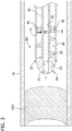
- tissue-removing catheter 10 for removing tissue from a body lumen is generally indicated at reference numeral 10.
- the illustrated tissue-removing catheter 10 is particularly suitable for removing tissue (e.g., plaque) from an occlusion that has totally occluded the body lumen in order to restore the patency of the lumen.
- the catheter 10 is suitable for removing tissue from a chronic total occlusion (CTO) in a vascular lumen (e.g., an artery).
- CTO chronic total occlusion
- the catheter 10 comprises a catheter body 12, a tissue-removing head, generally indicated at 14, at a distal end of the catheter body, and a rotatable driveshaft 16 operatively connected to the tissue-removing head for both rotating the tissue-removing head about head axis A and reciprocating the tissue-removing head along the head axis A.
- the tissue-removing head 14 extends distally outward from the distal end of the catheter body 12 and alternates between moving in a distal direction (indicated by arrow D1) from a proximal position relative to the catheter body ( FIG. 1 ) to a distal position ( FIG.
- tissue-removing head 14 reciprocates in this way simultaneously with rotating about the head axis A in a cutting direction (indicated by arrow D3).
- the catheter body 12 is elongate and at least a longitudinal portion thereof is generally flexible to allow the catheter body to navigate generally tortious body lumens.
- the catheter body 12 is generally tubular defining an inner lumen 20 ( FIGS. 3-5 ) extending along the catheter body in which the driveshaft 16 extends.
- a shearing blade 22 disposed at the distal end of the catheter body 12 shears tissue entering the inner lumen 20 during a tissue-removing operation of the catheter 10, as explained below.
- the illustrated shearing blade 22 has an annular shape with an inner opening partially defining the inner lumen.
- the catheter body 12 may comprise a torque tube including a coiled metal wire with plastic laminated over the coiled metal wire.
- a hypotube may be attached to a distal end of the torque tube.
- the hypotube may include the shearing blade 22 and may be formed from nitinol, stainless steel, carbide, cobalt chrome, MP35N, titanium, or high strength engineering plastic (e.g., radel, PEEK, delrin).
- the catheter body 12 may have other configurations and may be formed in other ways.
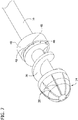
- the illustrated tissue-removing head 14 has a generally conical or dome-shape that tapers distally and is suitable for boring through tissue (e.g., plaque) occluding a body lumen.
- the tissue-removing head 14 includes a plurality of flutes 28, which in the illustrated embodiments are straight or linear as opposed to helical.
- the flutes 28 extend from a distal end toward a proximal end of the tissue-removing head and are spaced apart from one another around the head axis A.
- the flutes 28 define cutting edges that engage and remove tissue as the tissue-removing head 14 rotates and reciprocates about and along the head axis A.
- the tissue-removing head 14 may also have an abrasive exterior surface for abrading the tissue.
- an abrasive material may be applied to the exterior surface of the tissue-removing head 14 or the exterior surface may otherwise be formed to be abrasive.
- the tissue-removing head 14 may be formed from metal or other suitable material.
- the tissue-removing head may be of other configurations without departing from the scope of the present invention.
- the driveshaft 16 is rotatable and axially movable (so as to reciprocate) within the inner lumen 20 of the body 12.
- a distal end of driveshaft 16 is fixedly connected to the proximal end of the tissue-removing head 14 to impart rotation and reciprocating motion to the tissue-removing head.
- the driveshaft 16 may be formed separately from the tissue-removing head 14 or integrally formed therewith.
- the driveshaft 16 may be operatively connected to the tissue-removing head 14 in other ways suitable for imparting rotation to the tissue-removing head.
- the distal end portion of the driveshaft 16 includes a helical thread 36 (e.g., an Archimedes' blade) surrounding the longitudinal axis of the driveshaft.
- the illustrated thread 36 has a variable pitch, with the pitch being relatively coarse adjacent the distal end of the thread and fine (substantially flat) adjacent the proximal end.
- the helical thread 36 functions as a tissue-transport mechanism to transport removed tissue proximally within the inner lumen 20 of the catheter body 12.
- the variable pitch of the thread 36 maximizes the tissue transport speed due to the coarse pitch at a distal portion of the thread, and facilitates grinding or breaking up of tissue due to the fine pitch at a proximal portion of the thread, as explained in more detail below.
- the driveshaft may not include the thread 36.
- the driveshaft 16 is connected to the catheter body 12 via a bearing or driveshaft bushing 40 attached to the catheter body in the inner lumen 20.
- the illustrated driveshaft bushing 40 has a generally disk-shape defining a bearing opening 42 aligned axially with the catheter body 12, and tissue openings 44 radially outward of the bearing opening and spaced apart from one another around the bearing opening.
- the driveshaft 16 passes through the bearing opening 42 (e.g., a central bearing opening), which is sized and shaped snugly receive the driveshaft while at the same time allowing the driveshaft to rotate and move axially (i.e., reciprocate) relative to the bushing 40 and the catheter body 12.
- the tissue openings 44 are sized and shaped to receive removed tissue being transported proximally within the inner lumen 20 via the thread 36, as explained in more detail below.
- the proximal portion of the thread 36 is spaced axially from a distal face of the bushing 40 to define a space therebetween in the inner lumen 20.
- the tissue-removing head 14 and the driveshaft 16 are in the proximal position (see e.g., FIG. 5 )
- the proximal portion of the thread 36 is adjacent and/or flush against the distal face of the bushing 40. As shown in FIGS.
- the proximal end portion of the thread 36 includes grooves 48 (or ribs) or other structures which, along with the fine pitch of the thread, facilitate shearing and breaking up of removed tissue within the space between the thread and the bushing 40, as explained in more detail below.
- the tissue openings 44 in the bushing 40 also facilitate shearing and breaking up of removed tissue.
- the bushing 40 may include additional structures to facilitate shearing and breaking up of removed tissue.
- a control handle or other control device operatively connects to the proximal end of the catheter 10.
- the control handle includes a housing and at least one actuator in the housing for driving rotation and reciprocation of the driveshaft.
- the control handle may include a rotary actuator for rotating the driveshaft about the longitudinal axis and a linear actuator for reciprocating the driveshaft along the longitudinal axis.
- the rotary and linear actuators may share an electric motor or prime mover, or the actuators may have separate dedicated motors.
- the distal end of the catheter is delivered to a target site within a body lumen BL.
- the body lumen BL is a vascular lumen (e.g., an artery) and the target site is tissue (e.g., plaque) forming a chronic total occlusion CTO.
- the catheter 10 may be delivered to the target site over a guidewire (not shown).
- the illustrated catheter 10 has a guidewire lumen 50 extending through the driveshaft and the tissue-removing head for receiving a guidewire.
- the catheter 10 may be delivered to the target site in other ways without departing from the scope of the present invention.
- the catheter 10 can be activated using the control handle, such as by activating a control lever, button or other device to activate the at least one actuator.
- the driveshaft and the tissue-removing head both rotate about the head axis A and reciprocate along the head axis between the proximal and distal positions.
- the user may move the catheter body 12 distally toward the occlusion (as indicated by arrow D4).
- the tissue-removing head bores (or reams) into the occlusion CTO as it rotates and moves distally to the distal position.
- the tissue-removing head is boring, the tissue is cut by the cutting edges of the flutes 28 of the tissue-removing head 14, and simultaneously, the tissue is elastically compressed radially between the tissue-removing head and the wall of the body lumen BL, as indicated by arrows C.
- the tissue-removing head 14 passes distally beyond a portion of this radially compressed tissue, the tissue rebounds radially inwardly toward the driveshaft 16 and the thread 36.
- the thread 36 may engage the rebounded tissue and pull the tissue both toward the driveshaft 16 and proximally toward the shearing blade 22 of the catheter body 12. Moreover, from the distal position, the tissue-removing head 14 and the thread 36 move proximally (as indicated by the arrow D2) to pull the rebounded tissue proximally. During this proximal movement of the tissue-removing head 14 and the driveshaft 16 toward the proximal position, the rebounded tissue is sheared off from the occlusion as the thread and/or the tissue-removing head move proximally past the cutting blade 22 within the inner lumen 20. In the illustrated embodiment, as shown in FIG. 5 , at least a proximal portion of the tissue-removing head 14 passes into the opening of the shearing blade 22 to facilitate shearing of the tissue. The sheared off or removed tissue enters the inner lumen 20 of the catheter body 12.
- the removed tissue in the inner lumen 20 is transported proximally toward the bushing 40.
- tissue being transported via the thread 36 enters the space in the inner lumen 20 between the proximal end portion of the thread and the distal face of the driveshaft bushing 40.
- the driveshaft 16 moves proximally from the distal position ( FIG. 4 ) to the proximal position, the proximal end portion of the thread 36 compresses the removed tissue against the distal face of the bushing 40.
- Rotation of the thread 36 simultaneously with the thread moving proximally to compress the removed tissue both shears the removed tissue, thereby breaking the tissue into smaller fragments, and forces the removed tissue through the tissue openings 44 of the bushing 40.
- the removed tissue is stored in the inner lumen 20 of the catheter body 12 at a location proximal of the bushing 40.
- the catheter 10 continues the process of the tissue-removing head 14 entering tissue, the tissue compressing then rebounding around the proximal end of the tissue-removing head, the rebounded tissue being picked up by the thread 36 and then sheared off from the occlusion CTO when the tissue-removing head and the driveshaft 16 moved proximally.
Landscapes
- Health & Medical Sciences (AREA)
- Surgery (AREA)
- Life Sciences & Earth Sciences (AREA)
- Biomedical Technology (AREA)
- Nuclear Medicine, Radiotherapy & Molecular Imaging (AREA)
- Engineering & Computer Science (AREA)
- Vascular Medicine (AREA)
- Heart & Thoracic Surgery (AREA)
- Medical Informatics (AREA)
- Molecular Biology (AREA)
- Animal Behavior & Ethology (AREA)
- General Health & Medical Sciences (AREA)
- Public Health (AREA)
- Veterinary Medicine (AREA)
- Surgical Instruments (AREA)
Claims (18)
- Cathéter d'ablation de tissu (10) comprenant :un corps de cathéter (12) ayant des extrémités proximale et distale opposées ;une lame de cisaillement annulaire (22) fixée à l'extrémité distale du corps de cathéter (12) ; etune tête d'ablation de tissu (14) au niveau de l'extrémité distale du corps de cathéter (12), dans lequel la tête d'ablation de tissu (14) est configurée pour tourner (D3) autour d'un axe de tête par rapport au corps de cathéter (12), et le cathéter d'ablation de tissu étant caractérisé en ce que la tête d'ablation de tissu est configurée pour aller et venir (D1, D2) le long de l'axe de tête (A) par rapport au corps de cathéter (12) entre une position proximale, dans laquelle la tête d'ablation de tissu (14) est adjacente à la lame de cisaillement annulaire (22), et une position distale, dans laquelle la tête d'ablation de tissu (14) est espacée axialement de la lame de cisaillement annulaire (22).
- Cathéter d'ablation de tissu (10) selon la revendication 1, comprenant en outre une tige d'entraînement (16) reçue dans le et s'étendant le long du corps de cathéter (12), dans lequel la tige d'entraînement (16) peut tourner autour du corps de cathéter (12) et est reliée de façon opérationnelle à la tête d'ablation de tissu (14) pour communiquer une rotation (D3) de la tête d'ablation de tissu (14) autour de l'axe de tête (A).
- Cathéter d'ablation de tissu (10) selon la revendication 2, dans lequel la tige d'entraînement (16) est capable d'un mouvement de va-et-vient le long du corps de cathéter (12) et est reliée de façon opérationnelle à la tête d'ablation de tissu (14) pour communiquer un mouvement de va-et-vient (D2) de la tête d'ablation de tissu (14) autour de l'axe de tête (A).
- Cathéter d'ablation de tissu (10) selon la revendication 2, dans lequel la tige d'entraînement (16) a un axe longitudinal et inclut un filet hélicoïdal externe (36) entourant l'axe longitudinal, dans lequel le filet hélicoïdal externe (36) est configuré pour transporter un tissu retiré de façon proximale le long de la tige d'entraînement (16) et au sein du corps de cathéter (22) à mesure que la tige d'entraînement (16) tourne par rapport au corps de cathéter (12).
- Cathéter d'ablation de tissu (10) selon la revendication 4, dans lequel le filet hélicoïdal externe (36) s'étend de façon proximale le long de l'axe longitudinal à partir d'une position adjacente à la tête d'ablation de tissu (14).
- Cathéter d'ablation de tissu (10) selon la revendication 5, dans lequel le filet hélicoïdal externe (36) a un pas variable.
- Cathéter d'ablation de tissu (10) selon la revendication 6, dans lequel le pas variable du filet hélicoïdal externe (36) est relativement grossier adjacent à une extrémité distale du filet hélicoïdal externe (36) et relativement fin adjacent à une extrémité proximale du filet hélicoïdal externe.
- Cathéter d'ablation de tissu (10) selon la revendication 4, comprenant en outre une douille de tige d'entraînement (40) reçue dans le corps de cathéter (12) et définissant une ouverture de palier (42) s'étendant à travers des extrémités proximale et distale de la douille de tige d'entraînement (40), dans lequel la tige d'entraînement (16) s'étend à travers l'ouverture de palier (42).
- Cathéter d'ablation de tissu (10) selon la revendication 8, dans lequel la douille de tige d'entraînement (40) est solidarisée au corps de cathéter (12).
- Cathéter d'ablation de tissu (10) selon la revendication 8, dans lequel le palier de tige d'entraînement (40) définit une ouverture de tissu (44) disposée radialement vers l'extérieur à partir de l'ouverture de palier (42) et s'étendant à travers les extrémités proximale et distale de la douille de tige d'entraînement (40), dans lequel l'ouverture de tissu (44) est configurée pour permettre au tissu retiré transporté via le filet hélicoïdal externe (36) de passer de façon proximale à travers celui-ci.
- Cathéter d'ablation de tissu (10) selon la revendication 10, dans lequel l'ouverture de tissu (44) comprend une pluralité d'ouvertures de tissu (44) espacées les unes des autres autour de l'ouverture de palier (42).
- Cathéter d'ablation de tissu (10) selon la revendication 10, dans lequel le filet hélicoïdal externe (36) a une extrémité proximale configurée pour venir en butée contre l'extrémité distale du palier de tige d'entraînement (40) lorsque la tête d'ablation de tissu (14) est dans la position proximale.
- Cathéter d'ablation de tissu (10) selon la revendication 12, dans lequel l'extrémité proximale du filet hélicoïdal externe (36) inclut au moins l'une parmi des rainures et des nervures (48) pour faciliter un cisaillement et une rupture du tissu retiré entre l'extrémité proximale du filet hélicoïdal externe (36) et l'extrémité distale du palier de tige d'entraînement (40).
- Cathéter d'ablation de tissu (10) selon la revendication 1, dans lequel la tête d'ablation de tissu (24) et une forme généralement conique qui s'effile de façon distale.
- Cathéter d'ablation de tissu (10) selon la revendication 14, dans lequel la tête d'ablation de tissu (14) définit une pluralité de cannelures (18) s'étendant à partir d'une extrémité distale en direction d'une extrémité proximale de la tête d'ablation de tissu (14).
- Cathéter d'ablation de tissu (10) selon la revendication 15, dans lequel les cannelures (28) sont espacées les unes des autres autour de l'axe de tête (A).
- Cathéter d'ablation de tissu (10) selon la revendication 14, dans lequel la tête d'ablation de tissu (14) a une surface extérieure abrasive.
- Cathéter d'ablation de tissu (10) selon la revendication 1, dans lequel la lame de cisaillement annulaire (22) entoure une partie d'extrémité proximale de la tête d'ablation de tissu (14) lorsque la tête d'ablation de tissu est dans la position proximale.
Applications Claiming Priority (2)
| Application Number | Priority Date | Filing Date | Title |
|---|---|---|---|
| US201562184278P | 2015-06-25 | 2015-06-25 | |
| PCT/US2016/038819 WO2016210000A1 (fr) | 2015-06-25 | 2016-06-22 | Cathéter de retrait de tissu muni de tête de retrait de tissu à mouvement en va-et-vient |
Publications (2)
| Publication Number | Publication Date |
|---|---|
| EP3313302A1 EP3313302A1 (fr) | 2018-05-02 |
| EP3313302B1 true EP3313302B1 (fr) | 2019-12-04 |
Family
ID=56369211
Family Applications (1)
| Application Number | Title | Priority Date | Filing Date |
|---|---|---|---|
| EP16736327.4A Active EP3313302B1 (fr) | 2015-06-25 | 2016-06-22 | Cathéter de retrait de tissu muni de tête de retrait de tissu à mouvement en va-et-vient |
Country Status (3)
| Country | Link |
|---|---|
| US (1) | US10517632B2 (fr) |
| EP (1) | EP3313302B1 (fr) |
| WO (1) | WO2016210000A1 (fr) |
Families Citing this family (12)
| Publication number | Priority date | Publication date | Assignee | Title |
|---|---|---|---|---|
| US10631970B1 (en) * | 2016-04-05 | 2020-04-28 | Matt D. Pursley | Removal assist catheter for engaging IVC filter strut independent of strut orientation |
| EP3558410A4 (fr) * | 2016-12-23 | 2020-08-12 | Teleflex Medical Incorporated | Dispositif d'aspiration et d'irrigation pour chirurgie laparoscopique |
| US10765446B2 (en) * | 2017-02-20 | 2020-09-08 | Cardiovascular Systems, Inc. | Systems, methods and devices for removal of thrombus and/or soft plaque |
| WO2018175431A1 (fr) * | 2017-03-20 | 2018-09-27 | Penumbra, Inc. | Procédés et appareil d'élimination d'hémorragie intracrânienne |
| US20180280045A1 (en) * | 2017-04-04 | 2018-10-04 | Covidien Lp | Thrombectomy catheter device |
| US10925631B2 (en) | 2017-05-31 | 2021-02-23 | Terumo Kabushiki Kaisha | Medical device and method |
| US10687844B2 (en) * | 2018-11-14 | 2020-06-23 | Pavel Menn | Catheter atherector |
| US10945904B2 (en) | 2019-03-08 | 2021-03-16 | Auris Health, Inc. | Tilt mechanisms for medical systems and applications |
| US11457947B2 (en) * | 2019-11-06 | 2022-10-04 | C.R. Bard, Inc. | Endovascular translating scoring mechanism utilizing motorized blade |
| US20230248498A1 (en) * | 2019-12-18 | 2023-08-10 | Imperative Care, Inc. | Manually rotatable thrombus engagement tool |
| EP4358879A1 (fr) * | 2021-06-23 | 2024-05-01 | Bard Peripheral Vascular, Inc. | Appareils de croisement et d'athérectomie intravasculaires et leurs procédés d'utilisation |
| WO2026017851A1 (fr) * | 2024-07-18 | 2026-01-22 | Molecular Medical Solutions Limited | Dispositif de thrombectomie mécanique et cathéter |
Family Cites Families (35)
| Publication number | Priority date | Publication date | Assignee | Title |
|---|---|---|---|---|
| US5653696A (en) * | 1984-05-14 | 1997-08-05 | Surgical Systems & Instruments, Inc. | Stent unclogging method |
| US4749376A (en) | 1986-10-24 | 1988-06-07 | Intravascular Surgical Instruments, Inc. | Reciprocating working head catheter |
| US5116350B1 (en) | 1987-03-17 | 1997-06-17 | Cordis Corp | Catheter system having distal tip for opening obstructions |
| US4854325A (en) | 1987-11-09 | 1989-08-08 | Stevens Robert C | Reciprocating guidewire method |
| DE3801318A1 (de) | 1988-01-19 | 1989-07-27 | Stocksmeier Uwe | Medizinischer katheter mit schneidvorrichtung |
| US5071425A (en) | 1988-09-12 | 1991-12-10 | Devices For Vascular Intervention, Inc. | Atherectomy catheter and method of forming the same |
| GB8829182D0 (en) * | 1988-12-14 | 1989-01-25 | Univ Birmingham | Surgical instrument |
| US5431673A (en) | 1989-02-17 | 1995-07-11 | American Biomed, Inc. | Distal atherectomy catheter |
| US4994067A (en) | 1989-02-17 | 1991-02-19 | American Biomed, Inc. | Distal atherectomy catheter |
| DE4036570A1 (de) | 1990-11-16 | 1992-05-21 | Osypka Peter | Katheter zur verminderung oder beseitigung von verengungen in gefaessen |
| US5250059A (en) | 1992-01-22 | 1993-10-05 | Devices For Vascular Intervention, Inc. | Atherectomy catheter having flexible nose cone |
| US5643297A (en) * | 1992-11-09 | 1997-07-01 | Endovascular Instruments, Inc. | Intra-artery obstruction clearing apparatus and methods |
| US5372601A (en) | 1993-03-30 | 1994-12-13 | Lary; Banning G. | Longitudinal reciprocating incisor |
| US5366464A (en) | 1993-07-22 | 1994-11-22 | Belknap John C | Atherectomy catheter device |
| US5624457A (en) * | 1994-04-07 | 1997-04-29 | Devices For Vascular Intervention | Directional atherectomy device with flexible housing |
| US6027450A (en) * | 1994-12-30 | 2000-02-22 | Devices For Vascular Intervention | Treating a totally or near totally occluded lumen |
| US5882329A (en) * | 1997-02-12 | 1999-03-16 | Prolifix Medical, Inc. | Apparatus and method for removing stenotic material from stents |
| US6824550B1 (en) * | 2000-04-06 | 2004-11-30 | Norbon Medical, Inc. | Guidewire for crossing occlusions or stenosis |
| US6482217B1 (en) | 1998-04-10 | 2002-11-19 | Endicor Medical, Inc. | Neuro thrombectomy catheter |
| US20020058956A1 (en) * | 1999-09-17 | 2002-05-16 | John S. Honeycutt | Rotational atherectomy system with side balloon |
| BE1013974A3 (nl) * | 2001-02-16 | 2003-01-14 | Janssens Jacques Phillibert | Inrichting voor het nemen van een weefselstaal. |
| US20020138091A1 (en) * | 2001-03-23 | 2002-09-26 | Devonrex, Inc. | Micro-invasive nucleotomy device and method |
| WO2003024340A2 (fr) * | 2001-09-17 | 2003-03-27 | Hydrocision, Inc. | Appareil chirurgical d'abrasion rotatif |
| US6554846B2 (en) | 2001-09-28 | 2003-04-29 | Scimed Life Systems, Inc. | Sonic burr |
| US6951566B2 (en) | 2002-01-25 | 2005-10-04 | Scimed Life Systems, Inc. | Reciprocating cutting and dilating balloon |
| EP1557128B1 (fr) * | 2004-01-23 | 2007-03-07 | Cathenet Corporation | Dispositif d'athérectomie |
| US20060229646A1 (en) * | 2005-04-12 | 2006-10-12 | Sparks Kurt D | Forward-directed atherectomy catheter |
| US9492192B2 (en) | 2006-06-30 | 2016-11-15 | Atheromed, Inc. | Atherectomy devices, systems, and methods |
| WO2008057554A1 (fr) * | 2006-11-08 | 2008-05-15 | Cook Incorporated | Dispositif d'élimination d'un thrombus |
| US20090138031A1 (en) * | 2007-11-24 | 2009-05-28 | Tsukernik Vladimir B | Thrombectomy catheter with a helical cutter |
| US8784440B2 (en) | 2008-02-25 | 2014-07-22 | Covidien Lp | Methods and devices for cutting tissue |
| US20100125253A1 (en) | 2008-11-17 | 2010-05-20 | Avinger | Dual-tip Catheter System for Boring through Blocked Vascular Passages |
| CN103200886B (zh) | 2010-10-28 | 2015-07-29 | 科维蒂恩有限合伙公司 | 物质移除装置和使用方法 |
| US9750525B2 (en) | 2013-03-14 | 2017-09-05 | Cardiovascular Systems, Inc. | Devices, systems and methods for an oscillating crown drive for rotational atherectomy |
| US9936970B2 (en) | 2013-03-14 | 2018-04-10 | Cardiovascular Systems, Inc. | Devices, systems and methods for an oscillating crown drive for rotational atherectomy |
-
2016
- 2016-06-21 US US15/188,525 patent/US10517632B2/en active Active
- 2016-06-22 EP EP16736327.4A patent/EP3313302B1/fr active Active
- 2016-06-22 WO PCT/US2016/038819 patent/WO2016210000A1/fr not_active Ceased
Non-Patent Citations (1)
| Title |
|---|
| None * |
Also Published As
| Publication number | Publication date |
|---|---|
| US20160374717A1 (en) | 2016-12-29 |
| WO2016210000A1 (fr) | 2016-12-29 |
| EP3313302A1 (fr) | 2018-05-02 |
| US10517632B2 (en) | 2019-12-31 |
Similar Documents
| Publication | Publication Date | Title |
|---|---|---|
| EP3313302B1 (fr) | Cathéter de retrait de tissu muni de tête de retrait de tissu à mouvement en va-et-vient | |
| US11426193B2 (en) | Tissue-removing catheter including operational control mechanism | |
| US10874420B2 (en) | Tissue-removing catheter including urging mechanism | |
| US20210346051A1 (en) | Material removal device and method of use | |
| AU2005220069B2 (en) | Catheter for sucking, fragmenting removing material extractable from blood vessels | |
| US10154854B2 (en) | Atherectomy devices and methods | |
| US10478213B2 (en) | Tissue-removing catheter with adjustable cross-sectional dimension | |
| US8007506B2 (en) | Atherectomy devices and methods | |
| US8361094B2 (en) | Atherectomy devices and methods | |
| EP2037821B1 (fr) | Dispositifs d'athérectomie | |
| WO2019199931A1 (fr) | Cathéter d'aspiration à vortex hydrodynamique | |
| US20110112563A1 (en) | Atherectomy devices and methods | |
| US20080045986A1 (en) | Atherectomy devices and methods | |
| CN117580528A (zh) | 混合动脉粥样硬化切除装置 | |
| EP3441024B1 (fr) | Cathéter d'élimination de tissu | |
| US20140249554A1 (en) | Atherectomy devices and methods | |
| WO2014093159A1 (fr) | Dispositif de coupe à traversée excentrique |
Legal Events
| Date | Code | Title | Description |
|---|---|---|---|
| STAA | Information on the status of an ep patent application or granted ep patent |
Free format text: STATUS: THE INTERNATIONAL PUBLICATION HAS BEEN MADE |
|
| PUAI | Public reference made under article 153(3) epc to a published international application that has entered the european phase |
Free format text: ORIGINAL CODE: 0009012 |
|
| STAA | Information on the status of an ep patent application or granted ep patent |
Free format text: STATUS: REQUEST FOR EXAMINATION WAS MADE |
|
| 17P | Request for examination filed |
Effective date: 20171117 |
|
| AK | Designated contracting states |
Kind code of ref document: A1 Designated state(s): AL AT BE BG CH CY CZ DE DK EE ES FI FR GB GR HR HU IE IS IT LI LT LU LV MC MK MT NL NO PL PT RO RS SE SI SK SM TR |
|
| AX | Request for extension of the european patent |
Extension state: BA ME |
|
| DAV | Request for validation of the european patent (deleted) | ||
| DAX | Request for extension of the european patent (deleted) | ||
| GRAP | Despatch of communication of intention to grant a patent |
Free format text: ORIGINAL CODE: EPIDOSNIGR1 |
|
| STAA | Information on the status of an ep patent application or granted ep patent |
Free format text: STATUS: GRANT OF PATENT IS INTENDED |
|
| INTG | Intention to grant announced |
Effective date: 20190702 |
|
| GRAS | Grant fee paid |
Free format text: ORIGINAL CODE: EPIDOSNIGR3 |
|
| GRAA | (expected) grant |
Free format text: ORIGINAL CODE: 0009210 |
|
| STAA | Information on the status of an ep patent application or granted ep patent |
Free format text: STATUS: THE PATENT HAS BEEN GRANTED |
|
| AK | Designated contracting states |
Kind code of ref document: B1 Designated state(s): AL AT BE BG CH CY CZ DE DK EE ES FI FR GB GR HR HU IE IS IT LI LT LU LV MC MK MT NL NO PL PT RO RS SE SI SK SM TR |
|
| REG | Reference to a national code |
Ref country code: GB Ref legal event code: FG4D |
|
| REG | Reference to a national code |
Ref country code: CH Ref legal event code: EP |
|
| REG | Reference to a national code |
Ref country code: AT Ref legal event code: REF Ref document number: 1208419 Country of ref document: AT Kind code of ref document: T Effective date: 20191215 |
|
| REG | Reference to a national code |
Ref country code: DE Ref legal event code: R096 Ref document number: 602016025554 Country of ref document: DE |
|
| REG | Reference to a national code |
Ref country code: IE Ref legal event code: FG4D |
|
| REG | Reference to a national code |
Ref country code: NL Ref legal event code: MP Effective date: 20191204 |
|
| REG | Reference to a national code |
Ref country code: LT Ref legal event code: MG4D |
|
| PG25 | Lapsed in a contracting state [announced via postgrant information from national office to epo] |
Ref country code: LV Free format text: LAPSE BECAUSE OF FAILURE TO SUBMIT A TRANSLATION OF THE DESCRIPTION OR TO PAY THE FEE WITHIN THE PRESCRIBED TIME-LIMIT Effective date: 20191204 Ref country code: SE Free format text: LAPSE BECAUSE OF FAILURE TO SUBMIT A TRANSLATION OF THE DESCRIPTION OR TO PAY THE FEE WITHIN THE PRESCRIBED TIME-LIMIT Effective date: 20191204 Ref country code: NO Free format text: LAPSE BECAUSE OF FAILURE TO SUBMIT A TRANSLATION OF THE DESCRIPTION OR TO PAY THE FEE WITHIN THE PRESCRIBED TIME-LIMIT Effective date: 20200304 Ref country code: GR Free format text: LAPSE BECAUSE OF FAILURE TO SUBMIT A TRANSLATION OF THE DESCRIPTION OR TO PAY THE FEE WITHIN THE PRESCRIBED TIME-LIMIT Effective date: 20200305 Ref country code: FI Free format text: LAPSE BECAUSE OF FAILURE TO SUBMIT A TRANSLATION OF THE DESCRIPTION OR TO PAY THE FEE WITHIN THE PRESCRIBED TIME-LIMIT Effective date: 20191204 Ref country code: BG Free format text: LAPSE BECAUSE OF FAILURE TO SUBMIT A TRANSLATION OF THE DESCRIPTION OR TO PAY THE FEE WITHIN THE PRESCRIBED TIME-LIMIT Effective date: 20200304 Ref country code: LT Free format text: LAPSE BECAUSE OF FAILURE TO SUBMIT A TRANSLATION OF THE DESCRIPTION OR TO PAY THE FEE WITHIN THE PRESCRIBED TIME-LIMIT Effective date: 20191204 |
|
| PG25 | Lapsed in a contracting state [announced via postgrant information from national office to epo] |
Ref country code: HR Free format text: LAPSE BECAUSE OF FAILURE TO SUBMIT A TRANSLATION OF THE DESCRIPTION OR TO PAY THE FEE WITHIN THE PRESCRIBED TIME-LIMIT Effective date: 20191204 Ref country code: RS Free format text: LAPSE BECAUSE OF FAILURE TO SUBMIT A TRANSLATION OF THE DESCRIPTION OR TO PAY THE FEE WITHIN THE PRESCRIBED TIME-LIMIT Effective date: 20191204 |
|
| PG25 | Lapsed in a contracting state [announced via postgrant information from national office to epo] |
Ref country code: AL Free format text: LAPSE BECAUSE OF FAILURE TO SUBMIT A TRANSLATION OF THE DESCRIPTION OR TO PAY THE FEE WITHIN THE PRESCRIBED TIME-LIMIT Effective date: 20191204 |
|
| PG25 | Lapsed in a contracting state [announced via postgrant information from national office to epo] |
Ref country code: RO Free format text: LAPSE BECAUSE OF FAILURE TO SUBMIT A TRANSLATION OF THE DESCRIPTION OR TO PAY THE FEE WITHIN THE PRESCRIBED TIME-LIMIT Effective date: 20191204 Ref country code: EE Free format text: LAPSE BECAUSE OF FAILURE TO SUBMIT A TRANSLATION OF THE DESCRIPTION OR TO PAY THE FEE WITHIN THE PRESCRIBED TIME-LIMIT Effective date: 20191204 Ref country code: PT Free format text: LAPSE BECAUSE OF FAILURE TO SUBMIT A TRANSLATION OF THE DESCRIPTION OR TO PAY THE FEE WITHIN THE PRESCRIBED TIME-LIMIT Effective date: 20200429 Ref country code: ES Free format text: LAPSE BECAUSE OF FAILURE TO SUBMIT A TRANSLATION OF THE DESCRIPTION OR TO PAY THE FEE WITHIN THE PRESCRIBED TIME-LIMIT Effective date: 20191204 Ref country code: CZ Free format text: LAPSE BECAUSE OF FAILURE TO SUBMIT A TRANSLATION OF THE DESCRIPTION OR TO PAY THE FEE WITHIN THE PRESCRIBED TIME-LIMIT Effective date: 20191204 Ref country code: NL Free format text: LAPSE BECAUSE OF FAILURE TO SUBMIT A TRANSLATION OF THE DESCRIPTION OR TO PAY THE FEE WITHIN THE PRESCRIBED TIME-LIMIT Effective date: 20191204 |
|
| PG25 | Lapsed in a contracting state [announced via postgrant information from national office to epo] |
Ref country code: SM Free format text: LAPSE BECAUSE OF FAILURE TO SUBMIT A TRANSLATION OF THE DESCRIPTION OR TO PAY THE FEE WITHIN THE PRESCRIBED TIME-LIMIT Effective date: 20191204 Ref country code: IS Free format text: LAPSE BECAUSE OF FAILURE TO SUBMIT A TRANSLATION OF THE DESCRIPTION OR TO PAY THE FEE WITHIN THE PRESCRIBED TIME-LIMIT Effective date: 20200404 Ref country code: SK Free format text: LAPSE BECAUSE OF FAILURE TO SUBMIT A TRANSLATION OF THE DESCRIPTION OR TO PAY THE FEE WITHIN THE PRESCRIBED TIME-LIMIT Effective date: 20191204 |
|
| REG | Reference to a national code |
Ref country code: DE Ref legal event code: R097 Ref document number: 602016025554 Country of ref document: DE |
|
| REG | Reference to a national code |
Ref country code: AT Ref legal event code: MK05 Ref document number: 1208419 Country of ref document: AT Kind code of ref document: T Effective date: 20191204 |
|
| PLBE | No opposition filed within time limit |
Free format text: ORIGINAL CODE: 0009261 |
|
| STAA | Information on the status of an ep patent application or granted ep patent |
Free format text: STATUS: NO OPPOSITION FILED WITHIN TIME LIMIT |
|
| PG25 | Lapsed in a contracting state [announced via postgrant information from national office to epo] |
Ref country code: DK Free format text: LAPSE BECAUSE OF FAILURE TO SUBMIT A TRANSLATION OF THE DESCRIPTION OR TO PAY THE FEE WITHIN THE PRESCRIBED TIME-LIMIT Effective date: 20191204 |
|
| 26N | No opposition filed |
Effective date: 20200907 |
|
| PG25 | Lapsed in a contracting state [announced via postgrant information from national office to epo] |
Ref country code: PL Free format text: LAPSE BECAUSE OF FAILURE TO SUBMIT A TRANSLATION OF THE DESCRIPTION OR TO PAY THE FEE WITHIN THE PRESCRIBED TIME-LIMIT Effective date: 20191204 Ref country code: AT Free format text: LAPSE BECAUSE OF FAILURE TO SUBMIT A TRANSLATION OF THE DESCRIPTION OR TO PAY THE FEE WITHIN THE PRESCRIBED TIME-LIMIT Effective date: 20191204 Ref country code: SI Free format text: LAPSE BECAUSE OF FAILURE TO SUBMIT A TRANSLATION OF THE DESCRIPTION OR TO PAY THE FEE WITHIN THE PRESCRIBED TIME-LIMIT Effective date: 20191204 |
|
| PG25 | Lapsed in a contracting state [announced via postgrant information from national office to epo] |
Ref country code: IT Free format text: LAPSE BECAUSE OF FAILURE TO SUBMIT A TRANSLATION OF THE DESCRIPTION OR TO PAY THE FEE WITHIN THE PRESCRIBED TIME-LIMIT Effective date: 20191204 Ref country code: MC Free format text: LAPSE BECAUSE OF FAILURE TO SUBMIT A TRANSLATION OF THE DESCRIPTION OR TO PAY THE FEE WITHIN THE PRESCRIBED TIME-LIMIT Effective date: 20191204 |
|
| REG | Reference to a national code |
Ref country code: CH Ref legal event code: PL |
|
| GBPC | Gb: european patent ceased through non-payment of renewal fee |
Effective date: 20200622 |
|
| PG25 | Lapsed in a contracting state [announced via postgrant information from national office to epo] |
Ref country code: LU Free format text: LAPSE BECAUSE OF NON-PAYMENT OF DUE FEES Effective date: 20200622 |
|
| REG | Reference to a national code |
Ref country code: BE Ref legal event code: MM Effective date: 20200630 |
|
| PG25 | Lapsed in a contracting state [announced via postgrant information from national office to epo] |
Ref country code: CH Free format text: LAPSE BECAUSE OF NON-PAYMENT OF DUE FEES Effective date: 20200630 Ref country code: LI Free format text: LAPSE BECAUSE OF NON-PAYMENT OF DUE FEES Effective date: 20200630 Ref country code: GB Free format text: LAPSE BECAUSE OF NON-PAYMENT OF DUE FEES Effective date: 20200622 |
|
| PG25 | Lapsed in a contracting state [announced via postgrant information from national office to epo] |
Ref country code: BE Free format text: LAPSE BECAUSE OF NON-PAYMENT OF DUE FEES Effective date: 20200630 |
|
| PG25 | Lapsed in a contracting state [announced via postgrant information from national office to epo] |
Ref country code: TR Free format text: LAPSE BECAUSE OF FAILURE TO SUBMIT A TRANSLATION OF THE DESCRIPTION OR TO PAY THE FEE WITHIN THE PRESCRIBED TIME-LIMIT Effective date: 20191204 Ref country code: MT Free format text: LAPSE BECAUSE OF FAILURE TO SUBMIT A TRANSLATION OF THE DESCRIPTION OR TO PAY THE FEE WITHIN THE PRESCRIBED TIME-LIMIT Effective date: 20191204 Ref country code: CY Free format text: LAPSE BECAUSE OF FAILURE TO SUBMIT A TRANSLATION OF THE DESCRIPTION OR TO PAY THE FEE WITHIN THE PRESCRIBED TIME-LIMIT Effective date: 20191204 |
|
| PG25 | Lapsed in a contracting state [announced via postgrant information from national office to epo] |
Ref country code: MK Free format text: LAPSE BECAUSE OF FAILURE TO SUBMIT A TRANSLATION OF THE DESCRIPTION OR TO PAY THE FEE WITHIN THE PRESCRIBED TIME-LIMIT Effective date: 20191204 |
|
| PGFP | Annual fee paid to national office [announced via postgrant information from national office to epo] |
Ref country code: DE Payment date: 20250520 Year of fee payment: 10 |
|
| PGFP | Annual fee paid to national office [announced via postgrant information from national office to epo] |
Ref country code: FR Payment date: 20250520 Year of fee payment: 10 |
|
| PGFP | Annual fee paid to national office [announced via postgrant information from national office to epo] |
Ref country code: IE Payment date: 20250522 Year of fee payment: 10 |