EP3313696B1 - Système de réalité augmentée pour prévention d'angle mort dans un véhicule - Google Patents
Système de réalité augmentée pour prévention d'angle mort dans un véhicule Download PDFInfo
- Publication number
- EP3313696B1 EP3313696B1 EP16815372.4A EP16815372A EP3313696B1 EP 3313696 B1 EP3313696 B1 EP 3313696B1 EP 16815372 A EP16815372 A EP 16815372A EP 3313696 B1 EP3313696 B1 EP 3313696B1
- Authority
- EP
- European Patent Office
- Prior art keywords
- vehicle
- driver
- host vehicle
- display
- augmented reality
- Prior art date
- Legal status (The legal status is an assumption and is not a legal conclusion. Google has not performed a legal analysis and makes no representation as to the accuracy of the status listed.)
- Active
Links
Images




Classifications
-
- G—PHYSICS
- G06—COMPUTING OR CALCULATING; COUNTING
- G06T—IMAGE DATA PROCESSING OR GENERATION, IN GENERAL
- G06T19/00—Manipulating three-dimensional [3D] models or images for computer graphics
- G06T19/006—Mixed reality
-
- B—PERFORMING OPERATIONS; TRANSPORTING
- B60—VEHICLES IN GENERAL
- B60R—VEHICLES, VEHICLE FITTINGS, OR VEHICLE PARTS, NOT OTHERWISE PROVIDED FOR
- B60R1/00—Optical viewing arrangements; Real-time viewing arrangements for drivers or passengers using optical image capturing systems, e.g. cameras or video systems specially adapted for use in or on vehicles
- B60R1/02—Rear-view mirror arrangements
- B60R1/08—Rear-view mirror arrangements involving special optical features, e.g. avoiding blind spots, e.g. convex mirrors; Side-by-side associations of rear-view and other mirrors
- B60R1/081—Rear-view mirror arrangements involving special optical features, e.g. avoiding blind spots, e.g. convex mirrors; Side-by-side associations of rear-view and other mirrors avoiding blind spots, e.g. by using a side-by-side association of mirrors
-
- B—PERFORMING OPERATIONS; TRANSPORTING
- B60—VEHICLES IN GENERAL
- B60R—VEHICLES, VEHICLE FITTINGS, OR VEHICLE PARTS, NOT OTHERWISE PROVIDED FOR
- B60R1/00—Optical viewing arrangements; Real-time viewing arrangements for drivers or passengers using optical image capturing systems, e.g. cameras or video systems specially adapted for use in or on vehicles
- B60R1/12—Mirror assemblies combined with other articles, e.g. clocks
-
- B—PERFORMING OPERATIONS; TRANSPORTING
- B60—VEHICLES IN GENERAL
- B60R—VEHICLES, VEHICLE FITTINGS, OR VEHICLE PARTS, NOT OTHERWISE PROVIDED FOR
- B60R1/00—Optical viewing arrangements; Real-time viewing arrangements for drivers or passengers using optical image capturing systems, e.g. cameras or video systems specially adapted for use in or on vehicles
- B60R1/20—Real-time viewing arrangements for drivers or passengers using optical image capturing systems, e.g. cameras or video systems specially adapted for use in or on vehicles
- B60R1/22—Real-time viewing arrangements for drivers or passengers using optical image capturing systems, e.g. cameras or video systems specially adapted for use in or on vehicles for viewing an area outside the vehicle, e.g. the exterior of the vehicle
- B60R1/23—Real-time viewing arrangements for drivers or passengers using optical image capturing systems, e.g. cameras or video systems specially adapted for use in or on vehicles for viewing an area outside the vehicle, e.g. the exterior of the vehicle with a predetermined field of view
- B60R1/26—Real-time viewing arrangements for drivers or passengers using optical image capturing systems, e.g. cameras or video systems specially adapted for use in or on vehicles for viewing an area outside the vehicle, e.g. the exterior of the vehicle with a predetermined field of view to the rear of the vehicle
-
- B—PERFORMING OPERATIONS; TRANSPORTING
- B60—VEHICLES IN GENERAL
- B60R—VEHICLES, VEHICLE FITTINGS, OR VEHICLE PARTS, NOT OTHERWISE PROVIDED FOR
- B60R11/00—Arrangements for holding or mounting articles, not otherwise provided for
- B60R11/02—Arrangements for holding or mounting articles, not otherwise provided for for radio sets, television sets, telephones, or the like; Arrangement of controls thereof
- B60R11/0229—Arrangements for holding or mounting articles, not otherwise provided for for radio sets, television sets, telephones, or the like; Arrangement of controls thereof for displays, e.g. cathodic tubes
- B60R11/0235—Arrangements for holding or mounting articles, not otherwise provided for for radio sets, television sets, telephones, or the like; Arrangement of controls thereof for displays, e.g. cathodic tubes of flat type, e.g. LCD
-
- G—PHYSICS
- G06—COMPUTING OR CALCULATING; COUNTING
- G06F—ELECTRIC DIGITAL DATA PROCESSING
- G06F3/00—Input arrangements for transferring data to be processed into a form capable of being handled by the computer; Output arrangements for transferring data from processing unit to output unit, e.g. interface arrangements
- G06F3/14—Digital output to display device ; Cooperation and interconnection of the display device with other functional units
- G06F3/1423—Digital output to display device ; Cooperation and interconnection of the display device with other functional units controlling a plurality of local displays, e.g. CRT and flat panel display
-
- G—PHYSICS
- G06—COMPUTING OR CALCULATING; COUNTING
- G06F—ELECTRIC DIGITAL DATA PROCESSING
- G06F3/00—Input arrangements for transferring data to be processed into a form capable of being handled by the computer; Output arrangements for transferring data from processing unit to output unit, e.g. interface arrangements
- G06F3/14—Digital output to display device ; Cooperation and interconnection of the display device with other functional units
- G06F3/147—Digital output to display device ; Cooperation and interconnection of the display device with other functional units using display panels
-
- G—PHYSICS
- G06—COMPUTING OR CALCULATING; COUNTING
- G06V—IMAGE OR VIDEO RECOGNITION OR UNDERSTANDING
- G06V20/00—Scenes; Scene-specific elements
- G06V20/50—Context or environment of the image
- G06V20/56—Context or environment of the image exterior to a vehicle by using sensors mounted on the vehicle
-
- H—ELECTRICITY
- H04—ELECTRIC COMMUNICATION TECHNIQUE
- H04N—PICTORIAL COMMUNICATION, e.g. TELEVISION
- H04N23/00—Cameras or camera modules comprising electronic image sensors; Control thereof
- H04N23/60—Control of cameras or camera modules
- H04N23/63—Control of cameras or camera modules by using electronic viewfinders
-
- H—ELECTRICITY
- H04—ELECTRIC COMMUNICATION TECHNIQUE
- H04N—PICTORIAL COMMUNICATION, e.g. TELEVISION
- H04N23/00—Cameras or camera modules comprising electronic image sensors; Control thereof
- H04N23/60—Control of cameras or camera modules
- H04N23/698—Control of cameras or camera modules for achieving an enlarged field of view, e.g. panoramic image capture
-
- B—PERFORMING OPERATIONS; TRANSPORTING
- B60—VEHICLES IN GENERAL
- B60R—VEHICLES, VEHICLE FITTINGS, OR VEHICLE PARTS, NOT OTHERWISE PROVIDED FOR
- B60R1/00—Optical viewing arrangements; Real-time viewing arrangements for drivers or passengers using optical image capturing systems, e.g. cameras or video systems specially adapted for use in or on vehicles
- B60R1/12—Mirror assemblies combined with other articles, e.g. clocks
- B60R2001/1215—Mirror assemblies combined with other articles, e.g. clocks with information displays
-
- B—PERFORMING OPERATIONS; TRANSPORTING
- B60—VEHICLES IN GENERAL
- B60R—VEHICLES, VEHICLE FITTINGS, OR VEHICLE PARTS, NOT OTHERWISE PROVIDED FOR
- B60R1/00—Optical viewing arrangements; Real-time viewing arrangements for drivers or passengers using optical image capturing systems, e.g. cameras or video systems specially adapted for use in or on vehicles
- B60R1/12—Mirror assemblies combined with other articles, e.g. clocks
- B60R2001/1253—Mirror assemblies combined with other articles, e.g. clocks with cameras, video cameras or video screens
-
- B—PERFORMING OPERATIONS; TRANSPORTING
- B60—VEHICLES IN GENERAL
- B60R—VEHICLES, VEHICLE FITTINGS, OR VEHICLE PARTS, NOT OTHERWISE PROVIDED FOR
- B60R11/00—Arrangements for holding or mounting articles, not otherwise provided for
- B60R2011/0001—Arrangements for holding or mounting articles, not otherwise provided for characterised by position
- B60R2011/0003—Arrangements for holding or mounting articles, not otherwise provided for characterised by position inside the vehicle
- B60R2011/0012—Seats or parts thereof
- B60R2011/0017—Head-rests
-
- B—PERFORMING OPERATIONS; TRANSPORTING
- B60—VEHICLES IN GENERAL
- B60R—VEHICLES, VEHICLE FITTINGS, OR VEHICLE PARTS, NOT OTHERWISE PROVIDED FOR
- B60R2300/00—Details of viewing arrangements using cameras and displays, specially adapted for use in a vehicle
- B60R2300/30—Details of viewing arrangements using cameras and displays, specially adapted for use in a vehicle characterised by the type of image processing
- B60R2300/307—Details of viewing arrangements using cameras and displays, specially adapted for use in a vehicle characterised by the type of image processing virtually distinguishing relevant parts of a scene from the background of the scene
-
- B—PERFORMING OPERATIONS; TRANSPORTING
- B60—VEHICLES IN GENERAL
- B60R—VEHICLES, VEHICLE FITTINGS, OR VEHICLE PARTS, NOT OTHERWISE PROVIDED FOR
- B60R2300/00—Details of viewing arrangements using cameras and displays, specially adapted for use in a vehicle
- B60R2300/50—Details of viewing arrangements using cameras and displays, specially adapted for use in a vehicle characterised by the display information being shared, e.g. external display, data transfer to other traffic participants or centralised traffic controller
-
- B—PERFORMING OPERATIONS; TRANSPORTING
- B60—VEHICLES IN GENERAL
- B60R—VEHICLES, VEHICLE FITTINGS, OR VEHICLE PARTS, NOT OTHERWISE PROVIDED FOR
- B60R2300/00—Details of viewing arrangements using cameras and displays, specially adapted for use in a vehicle
- B60R2300/80—Details of viewing arrangements using cameras and displays, specially adapted for use in a vehicle characterised by the intended use of the viewing arrangement
- B60R2300/802—Details of viewing arrangements using cameras and displays, specially adapted for use in a vehicle characterised by the intended use of the viewing arrangement for monitoring and displaying vehicle exterior blind spot views
- B60R2300/8026—Details of viewing arrangements using cameras and displays, specially adapted for use in a vehicle characterised by the intended use of the viewing arrangement for monitoring and displaying vehicle exterior blind spot views in addition to a rear-view mirror system
-
- G—PHYSICS
- G06—COMPUTING OR CALCULATING; COUNTING
- G06T—IMAGE DATA PROCESSING OR GENERATION, IN GENERAL
- G06T2207/00—Indexing scheme for image analysis or image enhancement
- G06T2207/30—Subject of image; Context of image processing
- G06T2207/30248—Vehicle exterior or interior
- G06T2207/30252—Vehicle exterior; Vicinity of vehicle
-
- G—PHYSICS
- G09—EDUCATION; CRYPTOGRAPHY; DISPLAY; ADVERTISING; SEALS
- G09G—ARRANGEMENTS OR CIRCUITS FOR CONTROL OF INDICATING DEVICES USING STATIC MEANS TO PRESENT VARIABLE INFORMATION
- G09G2380/00—Specific applications
- G09G2380/10—Automotive applications
Definitions
- Embodiments of the present disclosure address the aforementioned need and others by providing various types of information to the vehicle driver.
- Such information can be used by the vehicle driver singularly or in conjunction with other information available to the vehicle driver in order to allow the driver to operate the vehicle in an increasingly safe manner and/or to reduce the likelihood of property damage and/or possible bodily injuries to the driver, etc.
- information is presented to the driver as an augmented reality environment such that the driver can "see through" objects that may be occluding the driver's vision.
- a method implemented in computer-executable instructions for displaying information about vehicle surroundings to a driver of a host vehicle includes obtaining vehicle environment data from one or more information sources.
- the vehicle environment data in one embodiment is indicative of at least a part of a scene occluded from view of a driver when operating the vehicle.
- the method also includes presenting to the driver of the vehicle, with the aid of a display, an augmented reality environment based on the vehicle surroundings data and representative of an area surrounding the vehicle but obstructed from operator view.
- a computer-readable medium having modules for conveying information to a vehicle driver regarding vehicle surroundings.
- the one or more modules includes an information gathering module configured to collect data from one or more information sources associated with one or more sensing zones, an augmented reality image rendering module configured to generate from the collected data one or more virtual design elements representative of objects occluded from view of the vehicle driver, and a display module configured to cause the virtual design elements to be presented to a display.
- the present disclosure relates to a system of information gathering devices, displays and associated programmed hardware, and their methods of use, that provide, for example, increased driver visibility and blind spot prevention in vehicles, such as Class 8 trucks.
- the systems and/or methods can be employed alone or can be employed to augment other blind spot prevention aids, such as side view mirrors, etc.
- the system is configured to employ augmented reality techniques and methodologies in order to "see-through" an obstruction in the driver's view.
- a driver's view in a tractor-trailer combination is very limited when changing lanes or backing up, for example, into a tight loading dock, due to the presence of occluding vehicle objects, such as the semi-trailer, the sleeper cab, if equipped, other cab structure, combinations thereof, etc.
- occluding vehicle objects such as the semi-trailer, the sleeper cab, if equipped, other cab structure, combinations thereof, etc.
- digital cameras, radar, lidar, thermal imaging devices and/or similar information gathering devices can be placed at various locations around the vehicle and/or associated trailer, if equipped. Additionally, one or more displays are placed around the vehicle at locations that may correspond to actual view points of the vehicle driver.
- Some examples of the placement of displays include the following: (1) a display provided at the rear of the sleeper or day cab in order to present the rear scene looking behind an associated trailer, as shown in FIGURE 7 ; (2) a display provided with the rear view mirror, as shown in FIGURE 8 ; (3) a display provided with the side view mirrors to augment the viewing capabilities of the mirrors, as shown in FIGURE 9 ; (4) one or more displays provided on each side of the driver seat, as shown in FIGURE 10 .
- augmented reality refers to any rendered image, article or object using a combination of real-world views that are merged with computer generated images.
- real and virtual are used throughout this detailed description and in the claims to distinguish between various types of images and/or objects.
- a real view or real image refers to any view or image of a real environment that is occupied by a user. These views are typically reproduced with still or video cameras.
- a virtual image or virtual object is any image or object that is generated by a computing device and which is associated with a virtual environment.
- virtual design element is used throughout this detailed description and in the claims to refer collectively to any type of virtual object, virtual image or virtual graphic that may be created by, or used with, the system.
- An augmented reality environment can be created by the combination of virtual images or objects with a real views or images.
- the real objects or images are provided naturally by a mirror or like reflective surface or a transparent surface, such as a window.
- the real objects or images are generated by, for example, one or more cameras and/or the like. It will be appreciated that the generation of an augmented reality environment or scene can use a single source of information, or a combination of any two or more sources of information described herein.
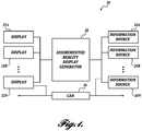
- FIGURE 1 there is shown a schematic diagram of one example of a vehicle safety system, generally designated 20, in accordance with aspects of the present disclosure.
- the system 20 may be installed in a suitable vehicle (sometimes referred to herein as the "host vehicle") for providing one or more benefits to the driver, such as improved driver visibility, reduction of blind spots, etc.
- a suitable vehicle sometimes referred to herein as the "host vehicle”
- This may include detecting or sensing an environment composed of one or more foreign objects (e.g. target object(s)) in relation to the host vehicle, which, for example, could pose a potential safety concern to the driver of the host vehicle, to a pedestrian in the vicinity of the host vehicle, to a driver of an adjacent vehicle, etc.
- foreign objects e.g. target object(s)
- the system 20 is capable of detecting or sensing a wide variety of different target objects, including both moving and non-moving objects.
- the target object can be a vehicle in an adjacent lane (e.g., a "side vehicle") or a vehicle approaching the vehicle from behind (e.g., a "rear trailing vehicle”).
- the target object may also be a pedestrian or animal either stationarily positioned or crossing behind the host vehicle, etc., or may be stationary, inanimate objects, such as trees, barriers, buildings, street signs, etc., on the periphery of or behind the vehicle.
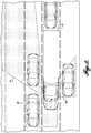
- FIGURE 2 illustrates various blind spots common to conventional vehicles, such as a tractor-trailer combination.
- typical blind spots include an area 40 located at the driver's side of the vehicle caused by the A pillar, the B pillar, the sleeper section or other structure of the cab. Area 40 is typically not accessible by the driver side mirrors.
- the blind spots also include an area 42 located behind the trailer.
- the blind spots also include an area 44 located at the passenger's side of the vehicle and at an angle with respect to the vehicle caused by the A pillar, the B pillar, the sleeper section or other structure of the cab.
- Area 44 is typically not accessible by the passenger side mirrors. In some instances, portions of area 44 may be slightly accessible by the side mirrors.
- the blind spots may also include an area 46 in front of the vehicle and to the passenger side of the vehicle caused by the front section/hood of the vehicle. Area 46 also extends rearwardly to include the area on the passenger side adjacent the vehicle front section/hood.
- the vehicle safety system 20 collects information from various information sources 24 associated with the host vehicle.
- the collected information represents data associated with the vehicle surroundings, sometimes referred to as the vehicle environment.
- the collected information represents data associated at least in part with one or more blind spots of the vehicle driver, including areas 40, 42, 44, and 46.
- the information sources 24 can include, for example, devices such as digital cameras, radar, lidar, thermal imaging cameras, etc., which are mounted on or otherwise associated with the host vehicle in suitable locations for obtaining information related to the driver's various blind spots or other occluded areas.
- the information sources 24 may include devices discrete from vehicle, such as traffic cameras, roadside beacons, components of system 20 or a similar system installed on third-party vehicles, which communicate with the host vehicle via cellular, short or long range RF, or similar protocols, and provide information related to the driver's various blind spots or other occluded areas.
- the information sources 24 may also optionally include devices that collect or generate data indicative of vehicle operating parameters, such as vehicle speed, vehicle acceleration, etc.
- the system 20 presents to the driver with the aid of one or more displays an augmented reality environment comprising a real image depicting a scene from the viewpoint of the driver and virtual design elements (e.g., person, animal, barrier, road, terrain, etc.) that are located in one of the driver's blind spots or occluded areas.
- the virtual design elements also include the object (e.g., trailer, vehicle structure (e.g., hood, cab, etc.), etc.) that is occluding the view of the driver.
- the object e.g., trailer, vehicle structure (e.g., hood, cab, etc.), etc.
- the presence of the virtual design elements allows the driver to "see through" the occluding structures, such as the trailer, in order to increase driver visibility, etc.
- the system 20 includes one or more information sources 24, an augmented reality display generator 28, and one or more displays 32.
- the display generator 28 is either directly connected in communication with one or more information sources 24 or can be connected to the one or more information sources 24 via a vehicle wide network 36, such as a controller area network (CAN).
- vehicle wide network 36 such as a controller area network (CAN).
- SAE Society of Automotive Engineers'
- SAE J1939 SAE J1708
- Direct connection can be carried out either wired or wirelessly, or both.
- the information sources 24 in some embodiments can include but are not limited to digital cameras or other image gathering devices, optical sensors, radar, lidar, ultrasonic or other RF sensors, thermal imaging cameras, thermal sensors, proximity sensors, etc.
- vehicle environment data which may, for example, contain camera images, an infrared image, etc., of the environment surrounding the host vehicle.
- the information contained in this vehicle environment data can be used by the system 20 to either generate real images, virtual images, or both.
- the information generating sources 24 are mounted to or otherwise associated with the host vehicle at one or more desired information gathering locations.
- the location and number of devices that are used will depend upon the particular application and can be readily modified as conditions dictate.
- the information sources 24 are placed around host vehicle (shown as a tractor trailer combination) so as to form side sensing zones 50 and 52 and a rear sensing zone 54.
- one or more information sources 24 can also be located around the host vehicle so as to form a front sensing zone 56.
- one or more information sources 24 can also be located at the rear of the lead vehicle (e.g., tractor) so as to form a gap sensing zone 58.
- additional information sources 24 can be optionally employed in order to carry out one or more functions of the system 20.
- some embodiments of the system 20 also employ various vehicle system sensors or the like, including brake sensors, wheel speed sensors, a vehicle speed sensor, transmission gear sensor, accelerometers, a steering angle sensor, etc.
- Information from these additional information sources can be used in conjunction with the information sources associated with the sensing zones 50, 52, 54, 56, and 58 in some embodiments in order to carry out various functionality of the system 20.
- At least one of the information sources 24 of the vehicle safety system 20 may optionally include a data acquisition unit that comprises one or more receivers.
- the data acquisition unit is configured to receive, for example, information from information sources discrete from the host vehicle, such as short-range communication devices (transmitters or the like from other vehicles in the vicinity of the host vehicle that are equipped with the system 20 or similar functionality, road side or traffic intersection beacons, traffic cameras, etc.).
- Information that can be transmitted to the vehicle 20 includes but is not limited to one or more of the following: vehicle operating data, blind spot data related to the host vehicle or to the transmitting vehicle, and incident data.
- the data acquisition unit may also include transmitters or can be equipped with transceivers in order to transmit information generated by system 20 to other vehicles in the vicinity of the host vehicle.
- the system 20 may be used in conjunction with other vehicle safety systems or functionality, such as adaptive cruise control, autonomous driving, collision avoidance, collision warning, lane departure warning, lane change/merge detection, object detection, vehicle path prediction, rear impact collision warning/avoidance, road condition detection, just to name a few.
- vehicle safety systems or functionality such as adaptive cruise control, autonomous driving, collision avoidance, collision warning, lane departure warning, lane change/merge detection, object detection, vehicle path prediction, rear impact collision warning/avoidance, road condition detection, just to name a few.
- the system 20 in one embodiment is configured to receive and/or share data with these optional vehicle systems in order to carry out the functionality of the system 20.
- the information from at least one these information sources 24, or any combination of these information sources 24, can be processed by the display generator 28 or other components so that an augmented reality environment can be presented to the vehicle driver with the aid of one or more of the displays 32.
- the augmented reality environment in some embodiments is created by the combination of a real image and one or more virtual design elements, which is presented together to the vehicle driver.
- the one or more displays 32 can include a generally opaque display, for example, a liquid crystal display (LCD), a light emitting polymer display (LPD), a plasma display, or a light emitting diode (LED) display.
- the augmented reality environment can be presented to the driver entirely by the opaque display.
- the one or more displays can include transparent displays or "see through" displays, such as transparent LCD, OLED or Head-up displays (HUD).
- the transparent display can be fabricated as a layer of OLEDs sandwiched between two transparent pieces of film (e.g., silicon or plastic film, etc.).
- the transparent displays can be either mounted directly over a mirror of the vehicle, such as a rearview mirror, a side view mirror, etc., or can overlay a vehicle window or sections thereof, such as a rear window or front windshield of the vehicle.
- the augmented reality environment is presented to the vehicle driver by a combination of a reflective or transparent layer (e.g., mirror, window, etc.) of the vehicle, which allows real images to be presented naturally to the driver via transmission of light, and a transparent display 32, which provides the virtual design elements to the driver.
- the display generator 28 is configured to: (1) collect information from one or more information sources 24; (2) generate virtual design elements based on the collected information; and (3) present the augmented reality environment or portions thereof to the vehicle driver via at least one of the one or more displays 32.
- the virtual design elements can include target objects, such as people, animals, posts, building structure, etc., as well as portions of the environment occluded by the host vehicle.
- the augmented reality environment provides a "see through" effect in order to represent information to the driver that would be normally hidden or obscured from view.
- the display generator 28 includes one or more modules.
- the display generator 28 includes an information gathering module 62, an augmented reality rendering module 66, and a display module 72. While the modules are separately illustrated in the embodiment shown, it will be appreciated that the functionality carried out by each module can be combined into fewer modules or further separated into additional modules.
- the modules of the display generator 28 contain logic rules for carrying out the functionality of the system. The logic rules in these and other embodiments can be implemented in hardware, in software, or combinations of hardware and software.
- the information gathering module 62 implements logic for obtaining real-time or near real time data from the information sources 24.
- the data can include images, video, etc., associated with one or more of the side sensing zones 50 and 52, the rear sensing zone 54, the front sensing zone 56, and the gap sensing zone 58. In some embodiments, only one zone is needed to generate the augmented reality environment. In other embodiments, a combination of two or more zones is used to generate the augmented reality environment or scene.
- the data can also optionally include vehicle operating data, or data from external sources (third party vehicles, beacons, traffic cameras, etc.) representing images or video associated with one or more of the various sensing zones.
- data received from the information sources 24 can be processed and temporary stored, such as in memory and/or an associated buffer.
- the augmented reality rendering module 66 implements logic for generating virtual design elements for the augmented reality environment based on information obtained from the information gathering module 62. In doing so, the augmented reality rendering module 66 can interpret various types of information and employ various augmented reality rendering engines for generating the augmented reality environment.
- the module 62 can convert radar, lidar, and/or thermal imaging into virtual design elements that graphically represent a scene, an image, or objects therein that are hidden or occluded from view of the driver.
- the module 66 converts a camera image into virtual design elements that graphically represent a scene, an image, or objects therein that are hidden or occluded from view of the driver.
- the augmented reality rendering module 78 also implements logic for presenting real images for the augmented reality environment based on information obtained from the information gathering module 62.
- the module 62 combines the real images and the virtual images in a suitable manner to form the augmented reality environment.
- the display generator 28 further includes a display module 72.
- the display module 72 implements logic for causing the virtual design elements generated by the augmented reality rendering module 78 to be presented to the display 32 for display.
- the display module 72 is further configured to present the virtual design elements together with the real images for display. It will be appreciated that know image processing, buffering, and/or the like can occur at one or more of the modules 62, 66, and 72.
- FIGURE 5 illustrates another suitable embodiment of the display generator 28 in block diagrammatic form.
- the display generator 28 includes a processor 76 and memory 78.
- the memory 78 may include computer readable storage media in read-only memory (ROM), random-access memory (RAM), and keep-alive memory (KAM), for example.
- the KAM may be used to store various operating variables or program instructions while the processor 76 is powered down.
- the computer-readable storage media may be implemented using any of a number of known memory devices such as PROMs (programmable read-only memory), EPROMs (electrically PROM), EEPROMs (electrically erasable PROM), flash memory, or any other electric, magnetic, optical, or combination memory devices capable of storing data, instructions, programs, modules, etc.
- a data acquisition module 62, an augmented reality 66, and a display module 66 are stored in memory 78.
- the display generator 28 may include additional components including but not limited to, analog to digital (A/D) and digital to analog (D/A) circuitry, input/output circuitry and devices (I/O) and appropriate signal conditioning and buffer circuitry.
- processor is not limited to integrated circuits referred to in the art as a computer, but broadly refers to a microcontroller, a microcomputer, a microprocessor, a programmable logic controller, an application specific integrated circuit, other programmable circuits, combinations of the above, among others. Therefore, as used herein, the term “processor” can be used to generally describe these aforementioned components, and can be either hardware or software, or combinations thereof, that implement logic for carrying out various aspects of the present disclosure. Similarly, the term “module” can include logic that may be implemented in either hardware or software, or combinations thereof.
- FIGURE 6 is a flow diagram that depicts one exemplary embodiment of an augmented reality display method 600 formed in accordance with the disclosed subject matter.
- the method 600 may be implemented by the modules 62, 66, and 72 of the display generator 36 from either FIGURE 4 or 5 .
- information may be collected or otherwise received from one or more information sources 24, converted into an augmented reality environment or virtual design elements thereof, and presented to the vehicle driver with the aid of one or more displays 32.
- the display generator 28 continually monitors and displays information. Accordingly, the method 600 operates continually until the display generator is powered down or its operation is otherwise interrupted.
- a start-up event is an event type that will cause the display 32 to transition from an inactive state to an active state.
- the start-up event that occurs at block 602 may be the ignition of the vehicle's engine, which results in power being supplied to an ignition bus.
- the display 32 may be put to "sleep" in a reduced power state when the vehicle is inactive for a predetermined period of time.
- the start-up event may be another type of event, such as the return of the display 32 from a reduced power state.
- the method 600 proceeds to block 604, where the display generator 28 begins collecting information from the one or more information sources 24 indicative of one or more events occurring in one or more of the sensing zones 50, 52, 54, 56, and 58.
- the display generator 28 renders one or more virtual design elements 80 representative of occluded objects located in one or more of the sensing zones for subsequent display.
- the virtual design elements 80 are rendered based on the driver's view point.
- the virtual design elements 80 can include, for example, a general outline of the occluding structure, such as the trailer, and any target objects that may be occluded thereby.
- the virtual design elements 80 can include an animal 80B, the road 80C, and the terrain 80D, that is normally occluded by the trailer, as shown in FIGURE 7 .
- the virtual design elements 80 can also include vehicle structure 80A, such as the outline of the trailer, that is responsible for the occluded view.
- the rendered virtual design elements 80 can be temporarily stored in memory 58 or an associated buffer. This information may be continually collected and processed so that current events can be conveyed on one or more displays 32.
- the method proceeds to block 608, where the virtual design elements are then presented to a display 32 for display.
- the virtual design elements are rendered by display 32, as shown in the examples of FIGURES 7-10 .
- the virtual design elements 80 are presented to the display 32 in conjunction with real images 82.
- real images 82 can be obtained or converted from the information provided from the information sources 24.
- the display generator 28 overlays, superimposes or otherwise combines the virtual design elements 80 with the real images 82 to form an augmented reality environment at block 610 for display.
- the display generator 28 takes the real image of the vehicle environment and converts only that portion of the real image that is occluded from the view of the driver into virtual design elements 80 in order to form an augmented reality environment.
- the real images 82 can be temporarily stored in memory 58 or an associated buffer. This information may be continually collected and processed so that current events can be conveyed on one or more displays 32.
- the method 600 then proceeds to block 612, where a determination is made as to whether a process termination event has occurred.
- the termination event can be turning the ignition key to the "off position, powering down the system 20 or one or more displays 32, or placing one or more of the displays 32 in sleep or stand-by mode, etc. If a termination event occurs at block 612, then the method 600 ends. If not, the method returns to block 604 so that a continuous feed is presented to the display 26.
- routine 600 described above with reference to FIGURE 6 does not show all of the functions performed when presenting the augmented reality environment to the driver. Instead, the routine 600 describes exemplary embodiments of the disclosed subject matter. Those skilled in the art and others will recognize that some functions may be performed in a different order, omitted/added, or otherwise varied without departing from the scope of the claimed subject matter.
- Carrying out the one or more embodiments of the method 600 results in augmented reality environments depicted schematically in the examples of FIGURES 7-10 .
- the real images 82 are shown with thicker lines, which appear darker in the FIGURES, while the virtual design elements are shown with thinner lines, which appear lighter in the FIGURES.
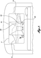
- FIGURE 7 is a schematic representation of a display 32 employed in lieu of the rear window of the host vehicle.
- the augmented reality environment is created by the virtual design elements 80A-80D and the real image 82 presented by the display 32.
- the virtual design elements include the outline of the occluding structure 80A, the animal 80B, the road 80C, and the terrain 80D, which are normally occluded by the trailer.
- information based on sensing zones 50, 52, 54, and/or 58 can be used.
- the real image 82 includes the scene behind the tractor that is not occluded by the trailer.
- a transparent display can be used in conjunction with the rear window in order to present the augmented reality environment to the driver.
- FIGURE 8 is a schematic representation of a display 32 mounted over a section of the rear view mirror 90.
- the augmented reality environment is created by the virtual design elements 80 presented by display 32 and the real image 82 presented by the reflective surface of the mirror 90.
- the virtual design elements include the trailer outline 80A, the road 80C, and the terrain 80D normally occluded by the trailer.
- FIGURE 9 is a schematic representation of a display 32 mounted over a section of the side view mirror 96.
- the augmented reality environment is created by the virtual design elements 80 presented by display 32 and the real image 82 presented by the reflective surface 98 of the mirror 96.
- the virtual design elements 80 include building 80E, portions of the flag 80F, and the outline of the trailer 80A,
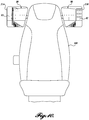
- FIGURE 10 is a schematic representation of two displays 32A and 32B mounted on the sides of the driver seat 100.
- the augmented reality environment is created by both the virtual design elements 80 and the real images 82 presented by displays 32A and 32B.
- the augment reality environment includes the occluded areas on the passenger and driver side of the trailer, which may be based on information from sensing zones 50, 52, and/or 54.
- the augment reality environment presented by such displays 32A and 32B can be used in conjunction with either traditional side mirrors, or side mirrors configured as described in FIGURE 9 .
- some of the information regarding the side sensing zones can be obtained from other vehicles in the vicinity of the host vehicle.
- the system 20 in one embodiment may be alternatively or additionally configured to employ a heads up display (HUD) as one of the displays 32 for presenting different configurations of the hood to the driver.
- HUD heads up display
- the display generator 28 of the system 20 is configured to generate virtual design elements in the form of the vehicle hood and objects that are present in area 46 (See FIGURE 2 ) but occluded by the front section/hood of the vehicle.
- the display generator 28 of the system 20 is configured to generate either virtual design elements or a real representation of a vehicle hood from a different vehicle model.
- the host vehicle may be a commercial truck, such as the Peterbilt® 389 semi-truck that is equipped with a "long" hood, but the system 20 may present through the HUD a virtual hood representative of a shorter version of the hood, sometimes referred to as the "aero" hood, or vice versa.
- a commercial truck such as the Peterbilt® 389 semi-truck that is equipped with a "long" hood
- the system 20 may present through the HUD a virtual hood representative of a shorter version of the hood, sometimes referred to as the "aero" hood, or vice versa.
- the system 20 may utilize information from other systems 20 installed in either trailing vehicles or leading vehicles.
- the host vehicle is part of a vehicle platoon (i.e., two or more vehicles one in front of the other)
- the system 20 of the host vehicle can communicate with the other vehicle(s) in order to provide the driver of the host vehicle with an augmented reality environment of what is in front of the lead vehicle, or what is behind the trailing vehicle.
- the augmented reality environment presented by the system 20 of the host vehicle allows the driver to "see through” the lead vehicle (the lead vehicle transmits information from in front of the lead vehicle, including area 46), thereby reducing driver eye fatigue, or allows the driver to "see through” the trailing vehicle (the trailing vehicle transmits information from behind the trailing vehicle, including from area 42), thereby providing the driver with additional information regarding the environment.
Landscapes
- Engineering & Computer Science (AREA)
- Multimedia (AREA)
- Theoretical Computer Science (AREA)
- Physics & Mathematics (AREA)
- General Physics & Mathematics (AREA)
- Mechanical Engineering (AREA)
- General Engineering & Computer Science (AREA)
- Human Computer Interaction (AREA)
- Signal Processing (AREA)
- Computer Hardware Design (AREA)
- Software Systems (AREA)
- Computer Graphics (AREA)
- Traffic Control Systems (AREA)
- User Interface Of Digital Computer (AREA)
- Navigation (AREA)
Claims (10)
- Procédé mis en œuvre dans des instructions exécutables sur ordinateur afin d'afficher des informations concernant les alentours d'un véhicule à un conducteur d'un véhicule hôte, dans lequel le véhicule hôte présente un écran (32), le procédé comprenant :- l'obtention de données relatives à l'environnement du véhicule à partir d'une ou plusieurs sources d'informations (24), les données relatives à l'environnement du véhicule étant indicatives d'au moins une partie d'une scène cachée à la vue du conducteur lorsqu'il conduit le véhicule hôte ; et- la présentation au conducteur, à l'aide de l'écran (32), d'un environnement en réalité augmentée basé sur les données relatives à l'environnement du véhicule et représentatives d'une zone entourant le véhicule hôte mais cachée à la vue du conducteur ;
caractérisé en ce que- le véhicule hôte fait partie d'un train de véhicules doté d'un véhicule suiveur,- le véhicule suiveur transmet des informations provenant de l'arrière du véhicule suiveur,- un système (20) du véhicule hôte communique avec l'autre ou les autres véhicules afin de fournir au conducteur du véhicule hôte un environnement en réalité augmentée de ce qui se trouve derrière le véhicule suiveur, dans lequel l'environnement en réalité augmentée présenté à l'aide de l'écran (32) du véhicule hôte permet au conducteur de « voir à travers » le véhicule suiveur,- soit l'écran (32) est un écran transparent recouvrant une vitre arrière du véhicule hôte, soit l'écran (32) est utilisé à la place de la vitre arrière du véhicule hôte. - Procédé selon la revendication 1, dans lequel ladite présentation inclut :- le réglage de l'écran (32) pour qu'il rende un ou plusieurs éléments de conception virtuelle représentatifs d'un ou plusieurs objets situés dans la scène cachée à la vue du conducteur du véhicule hôte.
- Procédé selon la revendication 1, dans lequel ladite présentation inclut :- la génération d'un ou plusieurs éléments de conception virtuelle représentatifs d'un ou plusieurs objets situés dans la scène cachée à la vue du conducteur du véhicule hôte ;- l'obtention d'une image réelle (82) de la scène, l'image réelle étant basée sur le point de vue du conducteur ; et- l'affichage des éléments de conception virtuelle et de l'image réelle ensemble par l'écran (32).
- Procédé selon la revendication 3, dans lequel ledit affichage des éléments de conception virtuelle et de l'image réelle (82) ensemble par l'écran (32) inclut :- l'agencement du ou des éléments de conception virtuelle sur une zone présélectionnée (40, 42, 44, 46) de l'image réelle.
- Procédé selon la revendication 1, dans lequel l'obtention de données relatives à l'environnement du véhicule inclut :- l'obtention de données supplémentaires à partir d'une source discrète du véhicule hôte, la source incluant un élément parmi une balise et une caméra de surveillance de la circulation.
- Procédé selon la revendication 1, dans lequel les données relatives à l'environnement du véhicule sont associées à une ou plusieurs zones de détection qui correspondent à une ou plusieurs zones extérieures du véhicule hôte, dans lequel la ou les zones extérieures du véhicule hôte représentent au moins en partie des zones cachées à la vue du conducteur lorsqu'il conduit le véhicule hôte.
- Procédé selon la revendication 1, dans lequel l'écran est un écran transparent recouvrant une vitre arrière du véhicule hôte.
- Procédé selon la revendication 1, dans lequel l'écran est utilisé à la place de la vitre arrière du véhicule hôte.
- Procédé selon la revendication 1, dans lequel les données incluent une vidéo associée à une zone de détection arrière.
- Support lisible sur ordinateur présentant des modules configurés pour convoyer des informations à un conducteur d'un véhicule hôte dans un train de véhicules concernant les environs du véhicule, dans lequel le train de véhicules inclut le véhicule hôte et un véhicule suiveur, en utilisant le procédé selon l'une quelconque des revendications 1 à 9.
Applications Claiming Priority (2)
| Application Number | Priority Date | Filing Date | Title |
|---|---|---|---|
| US14/751,891 US10373378B2 (en) | 2015-06-26 | 2015-06-26 | Augmented reality system for vehicle blind spot prevention |
| PCT/US2016/039234 WO2016210257A1 (fr) | 2015-06-26 | 2016-06-24 | Système de réalité augmentée pour prévention d'angle mort dans un véhicule |
Publications (3)
| Publication Number | Publication Date |
|---|---|
| EP3313696A1 EP3313696A1 (fr) | 2018-05-02 |
| EP3313696A4 EP3313696A4 (fr) | 2019-04-17 |
| EP3313696B1 true EP3313696B1 (fr) | 2021-05-05 |
Family
ID=57586464
Family Applications (1)
| Application Number | Title | Priority Date | Filing Date |
|---|---|---|---|
| EP16815372.4A Active EP3313696B1 (fr) | 2015-06-26 | 2016-06-24 | Système de réalité augmentée pour prévention d'angle mort dans un véhicule |
Country Status (6)
| Country | Link |
|---|---|
| US (2) | US10373378B2 (fr) |
| EP (1) | EP3313696B1 (fr) |
| AU (1) | AU2016283002B2 (fr) |
| CA (1) | CA2990430C (fr) |
| MX (1) | MX394028B (fr) |
| WO (1) | WO2016210257A1 (fr) |
Families Citing this family (33)
| Publication number | Priority date | Publication date | Assignee | Title |
|---|---|---|---|---|
| EP2972478B1 (fr) | 2013-03-15 | 2020-12-16 | Uatc, Llc | Procédés, systèmes, et appareil de vision stéréoscopique multi-sensorielle pour la robotique |
| US10373378B2 (en) | 2015-06-26 | 2019-08-06 | Paccar Inc | Augmented reality system for vehicle blind spot prevention |
| EP3353763A1 (fr) * | 2015-09-25 | 2018-08-01 | Apple Inc. | Système d'affichage à réalité augmentée |
| US12344158B1 (en) * | 2015-10-27 | 2025-07-01 | Jimmie L. Ewing | Commercial vehicle equipment signal system |
| US20170124881A1 (en) * | 2015-10-28 | 2017-05-04 | Velvac Incorporated | Blind zone warning for semi-trailer |
| US10077007B2 (en) * | 2016-03-14 | 2018-09-18 | Uber Technologies, Inc. | Sidepod stereo camera system for an autonomous vehicle |
| US10501018B2 (en) * | 2016-07-18 | 2019-12-10 | Panasonic Automotive Systems Company Of America, Division Of Panasonic Corporation Of North America | Head up side view mirror |
| US10496890B2 (en) * | 2016-10-28 | 2019-12-03 | International Business Machines Corporation | Vehicular collaboration for vehicular blind spot detection |
| EP3630542A1 (fr) * | 2017-05-22 | 2020-04-08 | Volvo Truck Corporation | Ensemble caméra destiné à une cabine de véhicule industriel |
| WO2018217498A1 (fr) * | 2017-05-22 | 2018-11-29 | Pcms Holdings, Inc. | Procédé et appareil de visualisation de réalité augmentée embarquée de plage et de champ de vision de capteur |
| CN109427199B (zh) * | 2017-08-24 | 2022-11-18 | 北京三星通信技术研究有限公司 | 用于辅助驾驶的增强现实的方法及装置 |
| US11455565B2 (en) * | 2017-08-31 | 2022-09-27 | Ford Global Technologies, Llc | Augmenting real sensor recordings with simulated sensor data |
| ES2704350B2 (es) * | 2017-09-15 | 2020-03-17 | Seat Sa | Método y sistema para mostrar información prioritaria en un vehículo |
| KR102436962B1 (ko) | 2017-09-19 | 2022-08-29 | 삼성전자주식회사 | 운송 장치에 구비된 전자 장치 및 이의 제어 방법 |
| US10967862B2 (en) | 2017-11-07 | 2021-04-06 | Uatc, Llc | Road anomaly detection for autonomous vehicle |
| US10549694B2 (en) * | 2018-02-06 | 2020-02-04 | GM Global Technology Operations LLC | Vehicle-trailer rearview vision system and method |
| DE102018203910B3 (de) * | 2018-03-14 | 2019-06-13 | Audi Ag | Fahrerassistenzsystem sowie Verfahren für ein Kraftfahrzeug zum Anzeigen einer erweiterten Realität |
| DE102018206494A1 (de) | 2018-04-26 | 2019-10-31 | Volkswagen Aktiengesellschaft | Verfahren zum Betreiben eines Anhängerrangierassistenzsystems eines Kraftfahrzeugs und Anhängerrangierassistenzsystem für ein Kraftfahrzeug |
| US10901416B2 (en) * | 2018-07-19 | 2021-01-26 | Honda Motor Co., Ltd. | Scene creation system for autonomous vehicles and methods thereof |
| JP6802226B2 (ja) * | 2018-09-12 | 2020-12-16 | 矢崎総業株式会社 | 車両用表示装置 |
| DE102018128634A1 (de) * | 2018-11-15 | 2020-05-20 | Valeo Schalter Und Sensoren Gmbh | Verfahren zum Bereitstellen einer visuellen Information über zumindest einen Teil einer Umgebung, Computerprogrammprodukt, mobiles Kommunikationsgerät und Kommunikationssystem |
| CN113677565B (zh) | 2019-03-01 | 2025-08-29 | 科迪亚克机器人股份有限公司 | 用于自主车辆的传感器组件 |
| KR102778258B1 (ko) * | 2019-07-29 | 2025-03-12 | 현대자동차주식회사 | 군집 주행 제어 장치, 그를 포함한 시스템 및 그 방법 |
| US20220363196A1 (en) * | 2019-10-03 | 2022-11-17 | Stoneridge Electronics A.B. | Vehicle display system with wearable display |
| US11180090B2 (en) | 2020-01-15 | 2021-11-23 | Toyota Motor Engineering & Manufacturing North America, Inc. | Apparatus and method for camera view selection/suggestion |
| WO2022045926A1 (fr) * | 2020-08-25 | 2022-03-03 | Общество с ограниченной ответственностью "МетроМедиа" | Wagon de transport en commun |
| US11753040B1 (en) | 2021-03-10 | 2023-09-12 | State Farm Mutual Automobile Insurance Company | Autonomous vehicle delivery |
| WO2023095939A1 (fr) * | 2021-11-24 | 2023-06-01 | 심용수 | Procédé d'amélioration de sécurité pour équipement industriel, et dispositif associé |
| DE102021130882A1 (de) * | 2021-11-25 | 2023-05-25 | Zf Cv Systems Global Gmbh | Fahrerassistenzsystem für ein Nutzfahrzeug mit einem Anhänger und Verfahren zur Steuerung eines solchen Systems |
| US12157416B2 (en) * | 2022-12-15 | 2024-12-03 | GM Global Technology Operations LLC | System and method for enhancing occupant awareness |
| US20240262193A1 (en) | 2023-02-06 | 2024-08-08 | Paccar Inc | Dual view vehicle display |
| US12485820B2 (en) | 2023-06-13 | 2025-12-02 | Ford Global Technologies, Llc | Systems and methods for detecting road obstructions |
| DE102023207409A1 (de) | 2023-08-02 | 2025-02-06 | Volkswagen Aktiengesellschaft | Verfahren und Vorrichtung zur Informationsausgabe in einem fahrenden Kraftfahrzeug |
Family Cites Families (43)
| Publication number | Priority date | Publication date | Assignee | Title |
|---|---|---|---|---|
| US5530421A (en) | 1994-04-26 | 1996-06-25 | Navistar International Transportation Corp. | Circuit for automated control of on-board closed circuit television system having side and rear view cameras |
| US8041483B2 (en) | 1994-05-23 | 2011-10-18 | Automotive Technologies International, Inc. | Exterior airbag deployment techniques |
| US5907293A (en) | 1996-05-30 | 1999-05-25 | Sun Microsystems, Inc. | System for displaying the characteristics, position, velocity and acceleration of nearby vehicles on a moving-map |
| US7983836B2 (en) * | 1997-10-22 | 2011-07-19 | Intelligent Technologies International, Inc. | Vehicle-traffic control device communication techniques |
| EP2267656A3 (fr) | 1998-07-31 | 2012-09-26 | Panasonic Corporation | Appareil d'affichage d'images et procédé d'affichage d'images |
| WO2001064481A2 (fr) | 2000-03-02 | 2001-09-07 | Donnelly Corporation | Systeme de miroir video integrant un module accessoire |
| US7852462B2 (en) | 2000-05-08 | 2010-12-14 | Automotive Technologies International, Inc. | Vehicular component control methods based on blind spot monitoring |
| DE10035223A1 (de) | 2000-07-20 | 2002-01-31 | Daimler Chrysler Ag | Vorrichtung und Verfahren zur Überwachung der Umgebung eines Objekts |
| US6424272B1 (en) | 2001-03-30 | 2002-07-23 | Koninklijke Philips Electronics, N.V. | Vehicular blind spot vision system |
| US6693519B2 (en) | 2001-05-31 | 2004-02-17 | V-Tech-Usa, Llc | Vehicle safety monitoring system for viewing blind spots |
| US20040001074A1 (en) * | 2002-05-29 | 2004-01-01 | Hideki Oyaizu | Image display apparatus and method, transmitting apparatus and method, image display system, recording medium, and program |
| AU2002368104A1 (en) | 2002-07-17 | 2004-02-09 | Fico Mirrors, Sa | Device and method for the active monitoring of the safety perimeter of a motor vehicle |
| US7466338B2 (en) | 2004-02-26 | 2008-12-16 | Yiling Xie | Wide-angled image display system for automobiles |
| JP2006072830A (ja) | 2004-09-03 | 2006-03-16 | Aisin Aw Co Ltd | 運転支援システム及び運転支援モジュール |
| US7593811B2 (en) | 2005-03-31 | 2009-09-22 | Deere & Company | Method and system for following a lead vehicle |
| US20060262140A1 (en) * | 2005-05-18 | 2006-11-23 | Kujawa Gregory A | Method and apparatus to facilitate visual augmentation of perceived reality |
| JP2008077628A (ja) | 2006-08-21 | 2008-04-03 | Sanyo Electric Co Ltd | 画像処理装置並びに車両周辺視界支援装置及び方法 |
| US8199975B2 (en) | 2006-12-12 | 2012-06-12 | Cognex Corporation | System and method for side vision detection of obstacles for vehicles |
| US8345098B2 (en) | 2008-03-17 | 2013-01-01 | International Business Machines Corporation | Displayed view modification in a vehicle-to-vehicle network |
| US8400507B2 (en) | 2008-03-17 | 2013-03-19 | International Business Machines Corporation | Scene selection in a vehicle-to-vehicle network |
| US8310353B2 (en) | 2008-03-31 | 2012-11-13 | Honda Motor Co., Ltd. | Vehicle blind spot detection and indicator system |
| EP2168815B1 (fr) | 2008-09-24 | 2014-06-04 | Robert Bosch GmbH | Procédé et dispositif pour détecter les objets éventuellement collidant dans une zone d'angle mort |
| CA2726186C (fr) | 2009-12-22 | 2018-01-02 | Marc Robert | Systeme de retroviseur exterieur a affichage video |
| US20120062741A1 (en) | 2010-09-03 | 2012-03-15 | Cvg Management Corporation | Vehicle camera system |
| DE102011010865A1 (de) | 2011-02-10 | 2012-03-08 | Daimler Ag | Fahrzeug mit einer Vorrichtung zur Erfassung einer Fahrzeugumgebung |
| US8744666B2 (en) | 2011-07-06 | 2014-06-03 | Peloton Technology, Inc. | Systems and methods for semi-autonomous vehicular convoys |
| US20130107044A1 (en) | 2011-10-26 | 2013-05-02 | Anthony Azevedo | Blind Spot Camera System |
| US9168871B2 (en) | 2011-10-28 | 2015-10-27 | Ford Global Technologies | Rear-view mirror with multi-mode display screen, system comprising same, and method of using same |
| US9139133B2 (en) | 2012-05-31 | 2015-09-22 | GM Global Technology Operations LLC | Vehicle collision warning system and method |
| DE102012213132B4 (de) | 2012-07-26 | 2020-03-12 | Bayerische Motoren Werke Aktiengesellschaft | Verfahren und Vorrichtung zur Fusion von Kameraaufnahmen von zumindest zwei Fahrzeugen |
| US9242602B2 (en) | 2012-08-27 | 2016-01-26 | Fotonation Limited | Rearview imaging systems for vehicle |
| US9139135B2 (en) | 2012-09-07 | 2015-09-22 | Musaid A. ASSAF | System and method that minimizes hazards of blind spots while driving |
| WO2014057231A1 (fr) * | 2012-10-10 | 2014-04-17 | Renault S.A.S. | Dispositif et procede d'affichage tete haute |
| US9743002B2 (en) | 2012-11-19 | 2017-08-22 | Magna Electronics Inc. | Vehicle vision system with enhanced display functions |
| WO2014130049A1 (fr) | 2013-02-25 | 2014-08-28 | Johnson Controls Technology Company | Systèmes et procédés d'affichage augmenté pour rétroviseurs |
| US10029621B2 (en) * | 2013-05-16 | 2018-07-24 | Ford Global Technologies, Llc | Rear view camera system using rear view mirror location |
| TWI552897B (zh) | 2013-05-17 | 2016-10-11 | 財團法人工業技術研究院 | 影像動態融合方法與裝置 |
| US9286725B2 (en) * | 2013-11-14 | 2016-03-15 | Nintendo Co., Ltd. | Visually convincing depiction of object interactions in augmented reality images |
| US9406114B2 (en) * | 2014-02-18 | 2016-08-02 | Empire Technology Development Llc | Composite image generation to remove obscuring objects |
| US9756319B2 (en) * | 2014-02-27 | 2017-09-05 | Harman International Industries, Incorporated | Virtual see-through instrument cluster with live video |
| US9713956B2 (en) * | 2015-03-05 | 2017-07-25 | Honda Motor Co., Ltd. | Vehicle-to-vehicle communication system providing a spatiotemporal look ahead and method thereof |
| US20160357262A1 (en) * | 2015-06-05 | 2016-12-08 | Arafat M.A. ANSARI | Smart vehicle |
| US10373378B2 (en) | 2015-06-26 | 2019-08-06 | Paccar Inc | Augmented reality system for vehicle blind spot prevention |
-
2015
- 2015-06-26 US US14/751,891 patent/US10373378B2/en active Active
-
2016
- 2016-06-24 AU AU2016283002A patent/AU2016283002B2/en active Active
- 2016-06-24 WO PCT/US2016/039234 patent/WO2016210257A1/fr not_active Ceased
- 2016-06-24 MX MX2017017176A patent/MX394028B/es unknown
- 2016-06-24 EP EP16815372.4A patent/EP3313696B1/fr active Active
- 2016-06-24 CA CA2990430A patent/CA2990430C/fr active Active
-
2019
- 2019-06-28 US US16/456,624 patent/US10909765B2/en active Active
Also Published As
| Publication number | Publication date |
|---|---|
| AU2016283002B2 (en) | 2020-02-20 |
| CA2990430A1 (fr) | 2016-12-29 |
| EP3313696A4 (fr) | 2019-04-17 |
| US10909765B2 (en) | 2021-02-02 |
| MX2017017176A (es) | 2018-11-09 |
| EP3313696A1 (fr) | 2018-05-02 |
| US20160379411A1 (en) | 2016-12-29 |
| AU2016283002A1 (en) | 2018-01-18 |
| MX394028B (es) | 2025-03-24 |
| US10373378B2 (en) | 2019-08-06 |
| BR112017027742A2 (pt) | 2019-07-16 |
| WO2016210257A1 (fr) | 2016-12-29 |
| US20190325659A1 (en) | 2019-10-24 |
| CA2990430C (fr) | 2023-10-10 |
Similar Documents
| Publication | Publication Date | Title |
|---|---|---|
| US10909765B2 (en) | Augmented reality system for vehicle blind spot prevention | |
| US12165420B2 (en) | Vehicular control system | |
| CN108602465B (zh) | 车辆用图像显示系统及搭载了该图像显示系统的车辆 | |
| US9499139B2 (en) | Vehicle monitoring system | |
| US11117520B2 (en) | Display control device, display control system, display control method, and program | |
| US10410514B2 (en) | Display device for vehicle and display method for vehicle | |
| US20180236939A1 (en) | Method, System, and Device for a Forward Vehicular Vision System | |
| US20190135169A1 (en) | Vehicle communication system using projected light | |
| US11256088B2 (en) | Vehicle display device | |
| US20200020235A1 (en) | Method, System, and Device for Forward Vehicular Vision | |
| US10836311B2 (en) | Information-presenting device | |
| CN116935695A (zh) | 用于具有增强现实抬头显示器的机动车辆的碰撞警告系统 | |
| US20240409113A1 (en) | Vehicle control device and vehicle control method | |
| US20200108721A1 (en) | Hud park assist | |
| US20260027971A1 (en) | Vehicle transparent display system and method | |
| BR112017027742B1 (pt) | Método, meio legível e sistema de realidade aumentada para prevenção de ponto cego de veículos |
Legal Events
| Date | Code | Title | Description |
|---|---|---|---|
| STAA | Information on the status of an ep patent application or granted ep patent |
Free format text: STATUS: THE INTERNATIONAL PUBLICATION HAS BEEN MADE |
|
| PUAI | Public reference made under article 153(3) epc to a published international application that has entered the european phase |
Free format text: ORIGINAL CODE: 0009012 |
|
| STAA | Information on the status of an ep patent application or granted ep patent |
Free format text: STATUS: REQUEST FOR EXAMINATION WAS MADE |
|
| 17P | Request for examination filed |
Effective date: 20180102 |
|
| AK | Designated contracting states |
Kind code of ref document: A1 Designated state(s): AL AT BE BG CH CY CZ DE DK EE ES FI FR GB GR HR HU IE IS IT LI LT LU LV MC MK MT NL NO PL PT RO RS SE SI SK SM TR |
|
| AX | Request for extension of the european patent |
Extension state: BA ME |
|
| DAV | Request for validation of the european patent (deleted) | ||
| DAX | Request for extension of the european patent (deleted) | ||
| RIC1 | Information provided on ipc code assigned before grant |
Ipc: B60R 1/02 20060101ALI20181205BHEP Ipc: G02B 27/00 20060101ALI20181205BHEP Ipc: B60R 1/00 20060101AFI20181205BHEP Ipc: B60R 1/12 20060101ALI20181205BHEP |
|
| A4 | Supplementary search report drawn up and despatched |
Effective date: 20190315 |
|
| RIC1 | Information provided on ipc code assigned before grant |
Ipc: B60R 1/00 20060101AFI20190311BHEP Ipc: B60R 1/12 20060101ALI20190311BHEP Ipc: G02B 27/00 20060101ALI20190311BHEP Ipc: B60R 1/02 20060101ALI20190311BHEP |
|
| STAA | Information on the status of an ep patent application or granted ep patent |
Free format text: STATUS: EXAMINATION IS IN PROGRESS |
|
| 17Q | First examination report despatched |
Effective date: 20200205 |
|
| GRAP | Despatch of communication of intention to grant a patent |
Free format text: ORIGINAL CODE: EPIDOSNIGR1 |
|
| STAA | Information on the status of an ep patent application or granted ep patent |
Free format text: STATUS: GRANT OF PATENT IS INTENDED |
|
| INTG | Intention to grant announced |
Effective date: 20201127 |
|
| GRAS | Grant fee paid |
Free format text: ORIGINAL CODE: EPIDOSNIGR3 |
|
| GRAA | (expected) grant |
Free format text: ORIGINAL CODE: 0009210 |
|
| STAA | Information on the status of an ep patent application or granted ep patent |
Free format text: STATUS: THE PATENT HAS BEEN GRANTED |
|
| AK | Designated contracting states |
Kind code of ref document: B1 Designated state(s): AL AT BE BG CH CY CZ DE DK EE ES FI FR GB GR HR HU IE IS IT LI LT LU LV MC MK MT NL NO PL PT RO RS SE SI SK SM TR |
|
| REG | Reference to a national code |
Ref country code: GB Ref legal event code: FG4D |
|
| REG | Reference to a national code |
Ref country code: CH Ref legal event code: EP |
|
| REG | Reference to a national code |
Ref country code: AT Ref legal event code: REF Ref document number: 1389426 Country of ref document: AT Kind code of ref document: T Effective date: 20210515 |
|
| REG | Reference to a national code |
Ref country code: DE Ref legal event code: R096 Ref document number: 602016057510 Country of ref document: DE |
|
| REG | Reference to a national code |
Ref country code: IE Ref legal event code: FG4D |
|
| REG | Reference to a national code |
Ref country code: NL Ref legal event code: FP |
|
| REG | Reference to a national code |
Ref country code: LT Ref legal event code: MG9D |
|
| REG | Reference to a national code |
Ref country code: AT Ref legal event code: MK05 Ref document number: 1389426 Country of ref document: AT Kind code of ref document: T Effective date: 20210505 |
|
| PG25 | Lapsed in a contracting state [announced via postgrant information from national office to epo] |
Ref country code: LT Free format text: LAPSE BECAUSE OF FAILURE TO SUBMIT A TRANSLATION OF THE DESCRIPTION OR TO PAY THE FEE WITHIN THE PRESCRIBED TIME-LIMIT Effective date: 20210505 Ref country code: FI Free format text: LAPSE BECAUSE OF FAILURE TO SUBMIT A TRANSLATION OF THE DESCRIPTION OR TO PAY THE FEE WITHIN THE PRESCRIBED TIME-LIMIT Effective date: 20210505 Ref country code: HR Free format text: LAPSE BECAUSE OF FAILURE TO SUBMIT A TRANSLATION OF THE DESCRIPTION OR TO PAY THE FEE WITHIN THE PRESCRIBED TIME-LIMIT Effective date: 20210505 Ref country code: BG Free format text: LAPSE BECAUSE OF FAILURE TO SUBMIT A TRANSLATION OF THE DESCRIPTION OR TO PAY THE FEE WITHIN THE PRESCRIBED TIME-LIMIT Effective date: 20210805 Ref country code: AT Free format text: LAPSE BECAUSE OF FAILURE TO SUBMIT A TRANSLATION OF THE DESCRIPTION OR TO PAY THE FEE WITHIN THE PRESCRIBED TIME-LIMIT Effective date: 20210505 |
|
| PG25 | Lapsed in a contracting state [announced via postgrant information from national office to epo] |
Ref country code: NO Free format text: LAPSE BECAUSE OF FAILURE TO SUBMIT A TRANSLATION OF THE DESCRIPTION OR TO PAY THE FEE WITHIN THE PRESCRIBED TIME-LIMIT Effective date: 20210805 Ref country code: PL Free format text: LAPSE BECAUSE OF FAILURE TO SUBMIT A TRANSLATION OF THE DESCRIPTION OR TO PAY THE FEE WITHIN THE PRESCRIBED TIME-LIMIT Effective date: 20210505 Ref country code: PT Free format text: LAPSE BECAUSE OF FAILURE TO SUBMIT A TRANSLATION OF THE DESCRIPTION OR TO PAY THE FEE WITHIN THE PRESCRIBED TIME-LIMIT Effective date: 20210906 Ref country code: SE Free format text: LAPSE BECAUSE OF FAILURE TO SUBMIT A TRANSLATION OF THE DESCRIPTION OR TO PAY THE FEE WITHIN THE PRESCRIBED TIME-LIMIT Effective date: 20210505 Ref country code: RS Free format text: LAPSE BECAUSE OF FAILURE TO SUBMIT A TRANSLATION OF THE DESCRIPTION OR TO PAY THE FEE WITHIN THE PRESCRIBED TIME-LIMIT Effective date: 20210505 Ref country code: LV Free format text: LAPSE BECAUSE OF FAILURE TO SUBMIT A TRANSLATION OF THE DESCRIPTION OR TO PAY THE FEE WITHIN THE PRESCRIBED TIME-LIMIT Effective date: 20210505 Ref country code: IS Free format text: LAPSE BECAUSE OF FAILURE TO SUBMIT A TRANSLATION OF THE DESCRIPTION OR TO PAY THE FEE WITHIN THE PRESCRIBED TIME-LIMIT Effective date: 20210905 Ref country code: GR Free format text: LAPSE BECAUSE OF FAILURE TO SUBMIT A TRANSLATION OF THE DESCRIPTION OR TO PAY THE FEE WITHIN THE PRESCRIBED TIME-LIMIT Effective date: 20210806 |
|
| PG25 | Lapsed in a contracting state [announced via postgrant information from national office to epo] |
Ref country code: SK Free format text: LAPSE BECAUSE OF FAILURE TO SUBMIT A TRANSLATION OF THE DESCRIPTION OR TO PAY THE FEE WITHIN THE PRESCRIBED TIME-LIMIT Effective date: 20210505 Ref country code: SM Free format text: LAPSE BECAUSE OF FAILURE TO SUBMIT A TRANSLATION OF THE DESCRIPTION OR TO PAY THE FEE WITHIN THE PRESCRIBED TIME-LIMIT Effective date: 20210505 Ref country code: RO Free format text: LAPSE BECAUSE OF FAILURE TO SUBMIT A TRANSLATION OF THE DESCRIPTION OR TO PAY THE FEE WITHIN THE PRESCRIBED TIME-LIMIT Effective date: 20210505 Ref country code: ES Free format text: LAPSE BECAUSE OF FAILURE TO SUBMIT A TRANSLATION OF THE DESCRIPTION OR TO PAY THE FEE WITHIN THE PRESCRIBED TIME-LIMIT Effective date: 20210505 Ref country code: DK Free format text: LAPSE BECAUSE OF FAILURE TO SUBMIT A TRANSLATION OF THE DESCRIPTION OR TO PAY THE FEE WITHIN THE PRESCRIBED TIME-LIMIT Effective date: 20210505 Ref country code: EE Free format text: LAPSE BECAUSE OF FAILURE TO SUBMIT A TRANSLATION OF THE DESCRIPTION OR TO PAY THE FEE WITHIN THE PRESCRIBED TIME-LIMIT Effective date: 20210505 Ref country code: CZ Free format text: LAPSE BECAUSE OF FAILURE TO SUBMIT A TRANSLATION OF THE DESCRIPTION OR TO PAY THE FEE WITHIN THE PRESCRIBED TIME-LIMIT Effective date: 20210505 |
|
| REG | Reference to a national code |
Ref country code: CH Ref legal event code: PL |
|
| REG | Reference to a national code |
Ref country code: DE Ref legal event code: R097 Ref document number: 602016057510 Country of ref document: DE |
|
| REG | Reference to a national code |
Ref country code: BE Ref legal event code: MM Effective date: 20210630 |
|
| PLBE | No opposition filed within time limit |
Free format text: ORIGINAL CODE: 0009261 |
|
| STAA | Information on the status of an ep patent application or granted ep patent |
Free format text: STATUS: NO OPPOSITION FILED WITHIN TIME LIMIT |
|
| PG25 | Lapsed in a contracting state [announced via postgrant information from national office to epo] |
Ref country code: MC Free format text: LAPSE BECAUSE OF FAILURE TO SUBMIT A TRANSLATION OF THE DESCRIPTION OR TO PAY THE FEE WITHIN THE PRESCRIBED TIME-LIMIT Effective date: 20210505 Ref country code: LU Free format text: LAPSE BECAUSE OF NON-PAYMENT OF DUE FEES Effective date: 20210624 |
|
| 26N | No opposition filed |
Effective date: 20220208 |
|
| PG25 | Lapsed in a contracting state [announced via postgrant information from national office to epo] |
Ref country code: LI Free format text: LAPSE BECAUSE OF NON-PAYMENT OF DUE FEES Effective date: 20210630 Ref country code: IE Free format text: LAPSE BECAUSE OF NON-PAYMENT OF DUE FEES Effective date: 20210624 Ref country code: CH Free format text: LAPSE BECAUSE OF NON-PAYMENT OF DUE FEES Effective date: 20210630 |
|
| PG25 | Lapsed in a contracting state [announced via postgrant information from national office to epo] |
Ref country code: IS Free format text: LAPSE BECAUSE OF FAILURE TO SUBMIT A TRANSLATION OF THE DESCRIPTION OR TO PAY THE FEE WITHIN THE PRESCRIBED TIME-LIMIT Effective date: 20210905 Ref country code: AL Free format text: LAPSE BECAUSE OF FAILURE TO SUBMIT A TRANSLATION OF THE DESCRIPTION OR TO PAY THE FEE WITHIN THE PRESCRIBED TIME-LIMIT Effective date: 20210505 |
|
| PG25 | Lapsed in a contracting state [announced via postgrant information from national office to epo] |
Ref country code: IT Free format text: LAPSE BECAUSE OF FAILURE TO SUBMIT A TRANSLATION OF THE DESCRIPTION OR TO PAY THE FEE WITHIN THE PRESCRIBED TIME-LIMIT Effective date: 20210505 Ref country code: BE Free format text: LAPSE BECAUSE OF NON-PAYMENT OF DUE FEES Effective date: 20210630 |
|
| PG25 | Lapsed in a contracting state [announced via postgrant information from national office to epo] |
Ref country code: CY Free format text: LAPSE BECAUSE OF FAILURE TO SUBMIT A TRANSLATION OF THE DESCRIPTION OR TO PAY THE FEE WITHIN THE PRESCRIBED TIME-LIMIT Effective date: 20210505 |
|
| PG25 | Lapsed in a contracting state [announced via postgrant information from national office to epo] |
Ref country code: HU Free format text: LAPSE BECAUSE OF FAILURE TO SUBMIT A TRANSLATION OF THE DESCRIPTION OR TO PAY THE FEE WITHIN THE PRESCRIBED TIME-LIMIT; INVALID AB INITIO Effective date: 20160624 |
|
| PG25 | Lapsed in a contracting state [announced via postgrant information from national office to epo] |
Ref country code: MK Free format text: LAPSE BECAUSE OF FAILURE TO SUBMIT A TRANSLATION OF THE DESCRIPTION OR TO PAY THE FEE WITHIN THE PRESCRIBED TIME-LIMIT Effective date: 20210505 |
|
| PG25 | Lapsed in a contracting state [announced via postgrant information from national office to epo] |
Ref country code: TR Free format text: LAPSE BECAUSE OF FAILURE TO SUBMIT A TRANSLATION OF THE DESCRIPTION OR TO PAY THE FEE WITHIN THE PRESCRIBED TIME-LIMIT Effective date: 20210505 |
|
| PG25 | Lapsed in a contracting state [announced via postgrant information from national office to epo] |
Ref country code: MT Free format text: LAPSE BECAUSE OF FAILURE TO SUBMIT A TRANSLATION OF THE DESCRIPTION OR TO PAY THE FEE WITHIN THE PRESCRIBED TIME-LIMIT Effective date: 20210505 |
|
| PGFP | Annual fee paid to national office [announced via postgrant information from national office to epo] |
Ref country code: DE Payment date: 20250627 Year of fee payment: 10 |
|
| PGFP | Annual fee paid to national office [announced via postgrant information from national office to epo] |
Ref country code: GB Payment date: 20250627 Year of fee payment: 10 |
|
| PGFP | Annual fee paid to national office [announced via postgrant information from national office to epo] |
Ref country code: NL Payment date: 20250626 Year of fee payment: 10 |
|
| PGFP | Annual fee paid to national office [announced via postgrant information from national office to epo] |
Ref country code: FR Payment date: 20250625 Year of fee payment: 10 |