EP3313779B1 - Procede et installation de production d'hydrogene a partir un melange de charge contenant un hydrogene et des hydrocarbures - Google Patents
Procede et installation de production d'hydrogene a partir un melange de charge contenant un hydrogene et des hydrocarbures Download PDFInfo
- Publication number
- EP3313779B1 EP3313779B1 EP16734313.6A EP16734313A EP3313779B1 EP 3313779 B1 EP3313779 B1 EP 3313779B1 EP 16734313 A EP16734313 A EP 16734313A EP 3313779 B1 EP3313779 B1 EP 3313779B1
- Authority
- EP
- European Patent Office
- Prior art keywords
- fluid
- pressure
- absorption
- methane
- hydrogen
- Prior art date
- Legal status (The legal status is an assumption and is not a legal conclusion. Google has not performed a legal analysis and makes no representation as to the accuracy of the status listed.)
- Not-in-force
Links
Images

Classifications
-
- C—CHEMISTRY; METALLURGY
- C01—INORGANIC CHEMISTRY
- C01B—NON-METALLIC ELEMENTS; COMPOUNDS THEREOF; METALLOIDS OR COMPOUNDS THEREOF NOT COVERED BY SUBCLASS C01C
- C01B3/00—Hydrogen; Gaseous mixtures containing hydrogen; Separation of hydrogen from mixtures containing it; Purification of hydrogen; Reversible storage of hydrogen
- C01B3/50—Separation of hydrogen or hydrogen-containing gases from gaseous mixtures, e.g. purification
- C01B3/506—Separation of hydrogen or hydrogen-containing gases from gaseous mixtures, e.g. purification at low temperatures
-
- B—PERFORMING OPERATIONS; TRANSPORTING
- B01—PHYSICAL OR CHEMICAL PROCESSES OR APPARATUS IN GENERAL
- B01D—SEPARATION
- B01D53/00—Separation of gases or vapours; Recovering vapours of volatile solvents from gases; Chemical or biological purification of waste gases, e.g. engine exhaust gases, smoke, fumes, flue gases, aerosols
- B01D53/002—Separation of gases or vapours; Recovering vapours of volatile solvents from gases; Chemical or biological purification of waste gases, e.g. engine exhaust gases, smoke, fumes, flue gases, aerosols by condensation
-
- B—PERFORMING OPERATIONS; TRANSPORTING
- B01—PHYSICAL OR CHEMICAL PROCESSES OR APPARATUS IN GENERAL
- B01D—SEPARATION
- B01D53/00—Separation of gases or vapours; Recovering vapours of volatile solvents from gases; Chemical or biological purification of waste gases, e.g. engine exhaust gases, smoke, fumes, flue gases, aerosols
- B01D53/02—Separation of gases or vapours; Recovering vapours of volatile solvents from gases; Chemical or biological purification of waste gases, e.g. engine exhaust gases, smoke, fumes, flue gases, aerosols by adsorption, e.g. preparative gas chromatography
- B01D53/04—Separation of gases or vapours; Recovering vapours of volatile solvents from gases; Chemical or biological purification of waste gases, e.g. engine exhaust gases, smoke, fumes, flue gases, aerosols by adsorption, e.g. preparative gas chromatography with stationary adsorbents
- B01D53/047—Pressure swing adsorption
-
- B—PERFORMING OPERATIONS; TRANSPORTING
- B01—PHYSICAL OR CHEMICAL PROCESSES OR APPARATUS IN GENERAL
- B01D—SEPARATION
- B01D53/00—Separation of gases or vapours; Recovering vapours of volatile solvents from gases; Chemical or biological purification of waste gases, e.g. engine exhaust gases, smoke, fumes, flue gases, aerosols
- B01D53/14—Separation of gases or vapours; Recovering vapours of volatile solvents from gases; Chemical or biological purification of waste gases, e.g. engine exhaust gases, smoke, fumes, flue gases, aerosols by absorption
- B01D53/1431—Pretreatment by other processes
-
- B—PERFORMING OPERATIONS; TRANSPORTING
- B01—PHYSICAL OR CHEMICAL PROCESSES OR APPARATUS IN GENERAL
- B01D—SEPARATION
- B01D53/00—Separation of gases or vapours; Recovering vapours of volatile solvents from gases; Chemical or biological purification of waste gases, e.g. engine exhaust gases, smoke, fumes, flue gases, aerosols
- B01D53/14—Separation of gases or vapours; Recovering vapours of volatile solvents from gases; Chemical or biological purification of waste gases, e.g. engine exhaust gases, smoke, fumes, flue gases, aerosols by absorption
- B01D53/18—Absorbing units; Liquid distributors therefor
-
- C—CHEMISTRY; METALLURGY
- C01—INORGANIC CHEMISTRY
- C01B—NON-METALLIC ELEMENTS; COMPOUNDS THEREOF; METALLOIDS OR COMPOUNDS THEREOF NOT COVERED BY SUBCLASS C01C
- C01B3/00—Hydrogen; Gaseous mixtures containing hydrogen; Separation of hydrogen from mixtures containing it; Purification of hydrogen; Reversible storage of hydrogen
- C01B3/50—Separation of hydrogen or hydrogen-containing gases from gaseous mixtures, e.g. purification
- C01B3/52—Separation of hydrogen or hydrogen-containing gases from gaseous mixtures, e.g. purification by contacting with liquids; Regeneration of used liquids
-
- C—CHEMISTRY; METALLURGY
- C01—INORGANIC CHEMISTRY
- C01B—NON-METALLIC ELEMENTS; COMPOUNDS THEREOF; METALLOIDS OR COMPOUNDS THEREOF NOT COVERED BY SUBCLASS C01C
- C01B3/00—Hydrogen; Gaseous mixtures containing hydrogen; Separation of hydrogen from mixtures containing it; Purification of hydrogen; Reversible storage of hydrogen
- C01B3/50—Separation of hydrogen or hydrogen-containing gases from gaseous mixtures, e.g. purification
- C01B3/56—Separation of hydrogen or hydrogen-containing gases from gaseous mixtures, e.g. purification by contacting with solids; Regeneration of used solids
-
- F—MECHANICAL ENGINEERING; LIGHTING; HEATING; WEAPONS; BLASTING
- F25—REFRIGERATION OR COOLING; COMBINED HEATING AND REFRIGERATION SYSTEMS; HEAT PUMP SYSTEMS; MANUFACTURE OR STORAGE OF ICE; LIQUEFACTION SOLIDIFICATION OF GASES
- F25J—LIQUEFACTION, SOLIDIFICATION OR SEPARATION OF GASES OR GASEOUS OR LIQUEFIED GASEOUS MIXTURES BY PRESSURE AND COLD TREATMENT OR BY BRINGING THEM INTO THE SUPERCRITICAL STATE
- F25J3/00—Processes or apparatus for separating the constituents of gaseous or liquefied gaseous mixtures involving the use of liquefaction or solidification
- F25J3/02—Processes or apparatus for separating the constituents of gaseous or liquefied gaseous mixtures involving the use of liquefaction or solidification by rectification, i.e. by continuous interchange of heat and material between a vapour stream and a liquid stream
- F25J3/0204—Processes or apparatus for separating the constituents of gaseous or liquefied gaseous mixtures involving the use of liquefaction or solidification by rectification, i.e. by continuous interchange of heat and material between a vapour stream and a liquid stream characterised by the feed stream
- F25J3/0219—Refinery gas, cracking gas, coke oven gas, gaseous mixtures containing aliphatic unsaturated CnHm or gaseous mixtures of undefined nature
-
- F—MECHANICAL ENGINEERING; LIGHTING; HEATING; WEAPONS; BLASTING
- F25—REFRIGERATION OR COOLING; COMBINED HEATING AND REFRIGERATION SYSTEMS; HEAT PUMP SYSTEMS; MANUFACTURE OR STORAGE OF ICE; LIQUEFACTION SOLIDIFICATION OF GASES
- F25J—LIQUEFACTION, SOLIDIFICATION OR SEPARATION OF GASES OR GASEOUS OR LIQUEFIED GASEOUS MIXTURES BY PRESSURE AND COLD TREATMENT OR BY BRINGING THEM INTO THE SUPERCRITICAL STATE
- F25J3/00—Processes or apparatus for separating the constituents of gaseous or liquefied gaseous mixtures involving the use of liquefaction or solidification
- F25J3/02—Processes or apparatus for separating the constituents of gaseous or liquefied gaseous mixtures involving the use of liquefaction or solidification by rectification, i.e. by continuous interchange of heat and material between a vapour stream and a liquid stream
- F25J3/0228—Processes or apparatus for separating the constituents of gaseous or liquefied gaseous mixtures involving the use of liquefaction or solidification by rectification, i.e. by continuous interchange of heat and material between a vapour stream and a liquid stream characterised by the separated product stream
- F25J3/0238—Processes or apparatus for separating the constituents of gaseous or liquefied gaseous mixtures involving the use of liquefaction or solidification by rectification, i.e. by continuous interchange of heat and material between a vapour stream and a liquid stream characterised by the separated product stream separation of CnHm with 2 carbon atoms or more
-
- F—MECHANICAL ENGINEERING; LIGHTING; HEATING; WEAPONS; BLASTING
- F25—REFRIGERATION OR COOLING; COMBINED HEATING AND REFRIGERATION SYSTEMS; HEAT PUMP SYSTEMS; MANUFACTURE OR STORAGE OF ICE; LIQUEFACTION SOLIDIFICATION OF GASES
- F25J—LIQUEFACTION, SOLIDIFICATION OR SEPARATION OF GASES OR GASEOUS OR LIQUEFIED GASEOUS MIXTURES BY PRESSURE AND COLD TREATMENT OR BY BRINGING THEM INTO THE SUPERCRITICAL STATE
- F25J3/00—Processes or apparatus for separating the constituents of gaseous or liquefied gaseous mixtures involving the use of liquefaction or solidification
- F25J3/02—Processes or apparatus for separating the constituents of gaseous or liquefied gaseous mixtures involving the use of liquefaction or solidification by rectification, i.e. by continuous interchange of heat and material between a vapour stream and a liquid stream
- F25J3/0228—Processes or apparatus for separating the constituents of gaseous or liquefied gaseous mixtures involving the use of liquefaction or solidification by rectification, i.e. by continuous interchange of heat and material between a vapour stream and a liquid stream characterised by the separated product stream
- F25J3/0252—Processes or apparatus for separating the constituents of gaseous or liquefied gaseous mixtures involving the use of liquefaction or solidification by rectification, i.e. by continuous interchange of heat and material between a vapour stream and a liquid stream characterised by the separated product stream separation of hydrogen
-
- C—CHEMISTRY; METALLURGY
- C01—INORGANIC CHEMISTRY
- C01B—NON-METALLIC ELEMENTS; COMPOUNDS THEREOF; METALLOIDS OR COMPOUNDS THEREOF NOT COVERED BY SUBCLASS C01C
- C01B2203/00—Integrated processes for the production of hydrogen or synthesis gas
- C01B2203/04—Integrated processes for the production of hydrogen or synthesis gas containing a purification step for the hydrogen or the synthesis gas
- C01B2203/0415—Purification by absorption in liquids
-
- C—CHEMISTRY; METALLURGY
- C01—INORGANIC CHEMISTRY
- C01B—NON-METALLIC ELEMENTS; COMPOUNDS THEREOF; METALLOIDS OR COMPOUNDS THEREOF NOT COVERED BY SUBCLASS C01C
- C01B2203/00—Integrated processes for the production of hydrogen or synthesis gas
- C01B2203/04—Integrated processes for the production of hydrogen or synthesis gas containing a purification step for the hydrogen or the synthesis gas
- C01B2203/042—Purification by adsorption on solids
-
- C—CHEMISTRY; METALLURGY
- C01—INORGANIC CHEMISTRY
- C01B—NON-METALLIC ELEMENTS; COMPOUNDS THEREOF; METALLOIDS OR COMPOUNDS THEREOF NOT COVERED BY SUBCLASS C01C
- C01B2203/00—Integrated processes for the production of hydrogen or synthesis gas
- C01B2203/04—Integrated processes for the production of hydrogen or synthesis gas containing a purification step for the hydrogen or the synthesis gas
- C01B2203/042—Purification by adsorption on solids
- C01B2203/043—Regenerative adsorption process in two or more beds, one for adsorption, the other for regeneration
-
- C—CHEMISTRY; METALLURGY
- C01—INORGANIC CHEMISTRY
- C01B—NON-METALLIC ELEMENTS; COMPOUNDS THEREOF; METALLOIDS OR COMPOUNDS THEREOF NOT COVERED BY SUBCLASS C01C
- C01B2203/00—Integrated processes for the production of hydrogen or synthesis gas
- C01B2203/04—Integrated processes for the production of hydrogen or synthesis gas containing a purification step for the hydrogen or the synthesis gas
- C01B2203/0465—Composition of the impurity
- C01B2203/048—Composition of the impurity the impurity being an organic compound
-
- C—CHEMISTRY; METALLURGY
- C01—INORGANIC CHEMISTRY
- C01B—NON-METALLIC ELEMENTS; COMPOUNDS THEREOF; METALLOIDS OR COMPOUNDS THEREOF NOT COVERED BY SUBCLASS C01C
- C01B2203/00—Integrated processes for the production of hydrogen or synthesis gas
- C01B2203/14—Details of the flowsheet
- C01B2203/146—At least two purification steps in series
- C01B2203/147—Three or more purification steps in series
-
- F—MECHANICAL ENGINEERING; LIGHTING; HEATING; WEAPONS; BLASTING
- F25—REFRIGERATION OR COOLING; COMBINED HEATING AND REFRIGERATION SYSTEMS; HEAT PUMP SYSTEMS; MANUFACTURE OR STORAGE OF ICE; LIQUEFACTION SOLIDIFICATION OF GASES
- F25J—LIQUEFACTION, SOLIDIFICATION OR SEPARATION OF GASES OR GASEOUS OR LIQUEFIED GASEOUS MIXTURES BY PRESSURE AND COLD TREATMENT OR BY BRINGING THEM INTO THE SUPERCRITICAL STATE
- F25J2200/00—Processes or apparatus using separation by rectification
- F25J2200/70—Refluxing the column with a condensed part of the feed stream, i.e. fractionator top is stripped or self-rectified
-
- F—MECHANICAL ENGINEERING; LIGHTING; HEATING; WEAPONS; BLASTING
- F25—REFRIGERATION OR COOLING; COMBINED HEATING AND REFRIGERATION SYSTEMS; HEAT PUMP SYSTEMS; MANUFACTURE OR STORAGE OF ICE; LIQUEFACTION SOLIDIFICATION OF GASES
- F25J—LIQUEFACTION, SOLIDIFICATION OR SEPARATION OF GASES OR GASEOUS OR LIQUEFIED GASEOUS MIXTURES BY PRESSURE AND COLD TREATMENT OR BY BRINGING THEM INTO THE SUPERCRITICAL STATE
- F25J2205/00—Processes or apparatus using other separation and/or other processing means
- F25J2205/02—Processes or apparatus using other separation and/or other processing means using simple phase separation in a vessel or drum
-
- F—MECHANICAL ENGINEERING; LIGHTING; HEATING; WEAPONS; BLASTING
- F25—REFRIGERATION OR COOLING; COMBINED HEATING AND REFRIGERATION SYSTEMS; HEAT PUMP SYSTEMS; MANUFACTURE OR STORAGE OF ICE; LIQUEFACTION SOLIDIFICATION OF GASES
- F25J—LIQUEFACTION, SOLIDIFICATION OR SEPARATION OF GASES OR GASEOUS OR LIQUEFIED GASEOUS MIXTURES BY PRESSURE AND COLD TREATMENT OR BY BRINGING THEM INTO THE SUPERCRITICAL STATE
- F25J2205/00—Processes or apparatus using other separation and/or other processing means
- F25J2205/02—Processes or apparatus using other separation and/or other processing means using simple phase separation in a vessel or drum
- F25J2205/04—Processes or apparatus using other separation and/or other processing means using simple phase separation in a vessel or drum in the feed line, i.e. upstream of the fractionation step
-
- F—MECHANICAL ENGINEERING; LIGHTING; HEATING; WEAPONS; BLASTING
- F25—REFRIGERATION OR COOLING; COMBINED HEATING AND REFRIGERATION SYSTEMS; HEAT PUMP SYSTEMS; MANUFACTURE OR STORAGE OF ICE; LIQUEFACTION SOLIDIFICATION OF GASES
- F25J—LIQUEFACTION, SOLIDIFICATION OR SEPARATION OF GASES OR GASEOUS OR LIQUEFIED GASEOUS MIXTURES BY PRESSURE AND COLD TREATMENT OR BY BRINGING THEM INTO THE SUPERCRITICAL STATE
- F25J2205/00—Processes or apparatus using other separation and/or other processing means
- F25J2205/30—Processes or apparatus using other separation and/or other processing means using a washing, e.g. "scrubbing" or bubble column for purification purposes
-
- F—MECHANICAL ENGINEERING; LIGHTING; HEATING; WEAPONS; BLASTING
- F25—REFRIGERATION OR COOLING; COMBINED HEATING AND REFRIGERATION SYSTEMS; HEAT PUMP SYSTEMS; MANUFACTURE OR STORAGE OF ICE; LIQUEFACTION SOLIDIFICATION OF GASES
- F25J—LIQUEFACTION, SOLIDIFICATION OR SEPARATION OF GASES OR GASEOUS OR LIQUEFIED GASEOUS MIXTURES BY PRESSURE AND COLD TREATMENT OR BY BRINGING THEM INTO THE SUPERCRITICAL STATE
- F25J2205/00—Processes or apparatus using other separation and/or other processing means
- F25J2205/40—Processes or apparatus using other separation and/or other processing means using hybrid system, i.e. combining cryogenic and non-cryogenic separation techniques
-
- F—MECHANICAL ENGINEERING; LIGHTING; HEATING; WEAPONS; BLASTING
- F25—REFRIGERATION OR COOLING; COMBINED HEATING AND REFRIGERATION SYSTEMS; HEAT PUMP SYSTEMS; MANUFACTURE OR STORAGE OF ICE; LIQUEFACTION SOLIDIFICATION OF GASES
- F25J—LIQUEFACTION, SOLIDIFICATION OR SEPARATION OF GASES OR GASEOUS OR LIQUEFIED GASEOUS MIXTURES BY PRESSURE AND COLD TREATMENT OR BY BRINGING THEM INTO THE SUPERCRITICAL STATE
- F25J2205/00—Processes or apparatus using other separation and/or other processing means
- F25J2205/60—Processes or apparatus using other separation and/or other processing means using adsorption on solid adsorbents, e.g. by temperature-swing adsorption [TSA] at the hot or cold end
-
- F—MECHANICAL ENGINEERING; LIGHTING; HEATING; WEAPONS; BLASTING
- F25—REFRIGERATION OR COOLING; COMBINED HEATING AND REFRIGERATION SYSTEMS; HEAT PUMP SYSTEMS; MANUFACTURE OR STORAGE OF ICE; LIQUEFACTION SOLIDIFICATION OF GASES
- F25J—LIQUEFACTION, SOLIDIFICATION OR SEPARATION OF GASES OR GASEOUS OR LIQUEFIED GASEOUS MIXTURES BY PRESSURE AND COLD TREATMENT OR BY BRINGING THEM INTO THE SUPERCRITICAL STATE
- F25J2210/00—Processes characterised by the type or other details of the feed stream
- F25J2210/12—Refinery or petrochemical off-gas
-
- F—MECHANICAL ENGINEERING; LIGHTING; HEATING; WEAPONS; BLASTING
- F25—REFRIGERATION OR COOLING; COMBINED HEATING AND REFRIGERATION SYSTEMS; HEAT PUMP SYSTEMS; MANUFACTURE OR STORAGE OF ICE; LIQUEFACTION SOLIDIFICATION OF GASES
- F25J—LIQUEFACTION, SOLIDIFICATION OR SEPARATION OF GASES OR GASEOUS OR LIQUEFIED GASEOUS MIXTURES BY PRESSURE AND COLD TREATMENT OR BY BRINGING THEM INTO THE SUPERCRITICAL STATE
- F25J2215/00—Processes characterised by the type or other details of the product stream
- F25J2215/62—Ethane or ethylene
-
- F—MECHANICAL ENGINEERING; LIGHTING; HEATING; WEAPONS; BLASTING
- F25—REFRIGERATION OR COOLING; COMBINED HEATING AND REFRIGERATION SYSTEMS; HEAT PUMP SYSTEMS; MANUFACTURE OR STORAGE OF ICE; LIQUEFACTION SOLIDIFICATION OF GASES
- F25J—LIQUEFACTION, SOLIDIFICATION OR SEPARATION OF GASES OR GASEOUS OR LIQUEFIED GASEOUS MIXTURES BY PRESSURE AND COLD TREATMENT OR BY BRINGING THEM INTO THE SUPERCRITICAL STATE
- F25J2230/00—Processes or apparatus involving steps for increasing the pressure of gaseous process streams
- F25J2230/08—Cold compressor, i.e. suction of the gas at cryogenic temperature and generally without afterstage-cooler
-
- F—MECHANICAL ENGINEERING; LIGHTING; HEATING; WEAPONS; BLASTING
- F25—REFRIGERATION OR COOLING; COMBINED HEATING AND REFRIGERATION SYSTEMS; HEAT PUMP SYSTEMS; MANUFACTURE OR STORAGE OF ICE; LIQUEFACTION SOLIDIFICATION OF GASES
- F25J—LIQUEFACTION, SOLIDIFICATION OR SEPARATION OF GASES OR GASEOUS OR LIQUEFIED GASEOUS MIXTURES BY PRESSURE AND COLD TREATMENT OR BY BRINGING THEM INTO THE SUPERCRITICAL STATE
- F25J2230/00—Processes or apparatus involving steps for increasing the pressure of gaseous process streams
- F25J2230/60—Processes or apparatus involving steps for increasing the pressure of gaseous process streams the fluid being hydrocarbons or a mixture of hydrocarbons
-
- F—MECHANICAL ENGINEERING; LIGHTING; HEATING; WEAPONS; BLASTING
- F25—REFRIGERATION OR COOLING; COMBINED HEATING AND REFRIGERATION SYSTEMS; HEAT PUMP SYSTEMS; MANUFACTURE OR STORAGE OF ICE; LIQUEFACTION SOLIDIFICATION OF GASES
- F25J—LIQUEFACTION, SOLIDIFICATION OR SEPARATION OF GASES OR GASEOUS OR LIQUEFIED GASEOUS MIXTURES BY PRESSURE AND COLD TREATMENT OR BY BRINGING THEM INTO THE SUPERCRITICAL STATE
- F25J2245/00—Processes or apparatus involving steps for recycling of process streams
- F25J2245/02—Recycle of a stream in general, e.g. a by-pass stream
-
- F—MECHANICAL ENGINEERING; LIGHTING; HEATING; WEAPONS; BLASTING
- F25—REFRIGERATION OR COOLING; COMBINED HEATING AND REFRIGERATION SYSTEMS; HEAT PUMP SYSTEMS; MANUFACTURE OR STORAGE OF ICE; LIQUEFACTION SOLIDIFICATION OF GASES
- F25J—LIQUEFACTION, SOLIDIFICATION OR SEPARATION OF GASES OR GASEOUS OR LIQUEFIED GASEOUS MIXTURES BY PRESSURE AND COLD TREATMENT OR BY BRINGING THEM INTO THE SUPERCRITICAL STATE
- F25J2270/00—Refrigeration techniques used
- F25J2270/02—Internal refrigeration with liquid vaporising loop
Definitions
- the invention relates to a method and a plant for the production of hydrogen from a hydrogen, methane and hydrocarbons containing two carbon atoms and poor or other hydrocarbon-free feed mixture according to the preambles of the independent claims.
- gas mixtures are obtained which after separation of water and oily constituents, if present (so-called pyrolysis oil), still essentially contain hydrogen, methane and hydrocarbons having two or more carbon atoms.
- pyrolysis oil Such gas mixtures can be separated into different separation sequences, as they are known to those skilled in principle and also described in the aforementioned article.
- the present invention relates to the separation treatment of resulting in such separation sequences gas mixtures containing hydrogen, methane and hydrocarbons having two carbon atoms and are low or free of other hydrocarbons.
- gas mixtures can be obtained for example in so-called deethanizers and further processed in so-called demethanizers.
- demethanizers methane is first separated together with hydrogen from the heavier components, ie the hydrocarbons with two carbon atoms.
- hydrocarbons having two carbon atoms still, as acetylene is typically hydrogenated upstream or downstream of the demethanizer predominantly or exclusively ethane and ethylene.
- the ethane which is then typically recycled for steam cracking, can be separated from the product ethylene.
- demethanizers can be operated at different pressures and are accordingly referred to as low-pressure (LP), medium-pressure (MP) and high-pressure (HP) demethanizers (high, Medium and low pressure demethanizer).
- LP low-pressure
- MP medium-pressure
- HP high-pressure demethanizers
- Hydrogen In addition to olefins such as ethylene, hydrogen is becoming increasingly important as a product of corresponding processes. Hydrogen, especially pure hydrogen, can be used for example in refineries for hydrogenation purposes and in some cases has a higher market value than the classical target compound of steam cracking, the ethylene.
- the CN 103449950 A discloses a demethanization process. This method comprises cooling a feed mixture and thereby forming condensates. Uncondensed portions of the feed mixture are subjected to countercurrent absorption. The condensates and a liquid forming in the countercurrent absorption are separated in a demethanizer column. To provide an absorption liquid for the countercurrent absorption, a fluid a temperature level well below that to which the uncondensed portions of the feed mixture are cooled and fed to the countercurrent absorption cooled. The required cooling capacity is provided by expansion cooling using a turboexpander. This is considered disadvantageous.
- Liquid and gaseous streams may be rich or poor in one or more components as used herein, with “rich” for a content of at least 50%, 75%, 90%, 95%, 99%, 99.5%, 99, 9% or 99.99% and “poor” for a content of at most 50%, 25%, 10%, 5%, 1%, 0.1% or 0.01% on a molar, weight or volume basis.
- the term “predominantly” can correspond to the definition of "rich”.
- Liquid and gaseous streams may also be enriched or depleted in one or more components as used herein, which terms refer to a corresponding level in a starting mixture from which the liquid or gaseous stream was obtained.
- the liquid or gaseous stream is "enriched” if it is at least 1.1 times, 1.5 times, 2 times, 5 times, 10 times, 100 times or 1000 times, "depleted” if it is at most 0.9 times, 0.5 times, 0.1 times, 0.01 times or 0.001 times the content of a corresponding Component, based on the starting mixture contains.
- the term “methane” or “hydrogen” is used, which is understood as meaning a stream which is rich in the corresponding component but does not have to consist exclusively of it.
- a liquid or gaseous stream is "derived" from another liquid or gaseous stream (also referred to as the exit stream) if it has at least some components contained in or from the exit stream.
- a stream derived in this sense may be obtained from the output stream by separating or branching off a partial stream or one or more components, enriching or depleting one or more components, chemically or physically reacting one or more components, heating, cooling, pressurizing, and the like.
- distillation columns and absorption columns can be used.
- relevant textbooks see, for example K. Sattler: Thermal separation process. Basics, design, apparatuses. Weinheim: Wiley-VCH, 3rd edition 2001 ).
- at least one liquid fraction ("bottom liquid”) and one gaseous fraction ("top gas”) in a bottom (“bottom”) or top (“top”) region are always removable from a distillation column and an absorption column.
- distillation column in the language used here is a separation column which is set up at least partially for a gaseous or liquid or in the form of a two-phase mixture with liquid and gaseous fractions, possibly also in the supercritical state To separate, ie from the mixture each pure substances or mixtures to produce enriched or depleted compared to the mixture with respect to at least one component or rich or poor in the above-explained sense.
- distillation columns are formed as cylindrical metal containers with internals, such as sieve trays or ordered or disordered Packs, are equipped.
- a distillation column is characterized inter alia by the fact that the bottom product is heated by means of a bottom evaporator, so that a part continuously evaporated and rises in the distillation column in gaseous form.
- a distillation column is also typically provided with a so-called top condenser, in which at least a portion of the top gas is liquefied into a condensate and fed as a liquid reflux at the top of the distillation column.
- part of the top gas can also be used elsewhere, for example as a product.
- an "absorption column” typically does not have a bottom evaporator.
- Absorption columns are also generally known in the field of separation technology. Absorption columns are used for absorption in the phase countercurrent and therefore also referred to as countercurrent columns. In countercurrent absorption, the donating gaseous phase flows upwardly through an absorption column. The receiving solution phase flows, abandoned from the top and withdrawn below, the gas phase. The gas phase is "washed” with the solution phase.
- internals are also typically provided, which provide for a gradual (soils, spray zones, rotating plates, etc.) or continuous (random beds of packing, packages, etc.) phase contact.
- pressure level and "temperature level” to characterize pressures and temperatures, thereby indicating that corresponding pressures and temperatures in a given plant need not be used in the form of exact pressure or temperature values to realize the innovative concept.
- pressures and temperatures typically range in certain ranges that are, for example, ⁇ 1%, 5%, 10%, 20% or even 50% about an average.
- Corresponding pressure levels and temperature levels can be in disjoint areas or in areas that overlap one another.
- pressure levels include unavoidable or expected pressure drops, for example, due to cooling effects.
- the pressure levels indicated here in bar are absolute pressures.
- the present invention exhibits its particular advantages in processes for the separation treatment of hydrogen, methane and hydrocarbons containing gas mixtures containing two carbon atoms, in which a low-pressure demethanizer explained in the introduction is used. While a high pressure demethanizer can typically remove a methane-rich liquid at the top which is suitable as reflux in an absorption column, this is not the case in low pressure demethanizers.
- the invention proposes a process for the recovery of hydrogen from a particular gaseous, to hydrogen, methane and hydrocarbons having two carbon atoms rich or hydrogen, methane and hydrocarbons with two Carbon-containing and poor in other hydrocarbons or free feed mixture before.
- a corresponding feed mixture is, as explained above, for example, formed from a product mixture of a steam cracking process, but can in principle also come from other sources.
- a feed mixture in the context of the present invention has already been freed of components which may interfere with the use of low temperatures, in particular of water and carbon dioxide. Further, the feed mixture in the present invention contains few or no hydrocarbons having three or more carbon atoms.
- the hydrocarbons having two carbon atoms may be predominantly ethane and ethylene, but acetylene may also be present in such a feed mixture, in particular if, for example by a steam cracking process, no hydrogenation of corresponding compounds has been carried out.
- fluid of such a feed mixture is cooled at a first pressure level from a first temperature level to a second temperature level in such a way that one or more condensates are deposited from the fluid of the feed mixture while leaving a residual gas.
- the method according to the invention does not differ appreciably from prior art methods.
- it is known in such processes to cool a corresponding feed mixture in several stages for example using C2 refrigerants, in particular ethylene.
- cooling takes place, for example, first with ethylene to about -57 ° C, wherein a first condensate is deposited.
- a remaining gaseous residue (residual gas) is then further cooled with ethylene to about -80 ° C and another condensate is deposited.
- residual gas residual gas
- FIG. 1 Another condensate deposited after further cooling of the remaining gaseous here to about -100 ° C.
- the temperature of the last cooling stage, in which a condensate is deposited from a corresponding feed mixture on which, however, no separation devices are used, in which further streams are fed referred to as "second temperature level”
- the temperature, in which the feed mixture is supplied to the cooling referred to as "first temperature level”.
- the first temperature level is especially at -35 to -45 ° C, the other temperature levels are explained below.
- the residual gaseous gas remaining at the second temperature level is further cooled to a third temperature level and subjected to countercurrent absorption to obtain a head gas rich in hydrogen and methane and a bottoms liquid.
- Fluid from the countercurrent absorption condensate (s) formed during the cooling is depressurized to a second pressure level and fed to a low pressure demethanizer at that second pressure level.
- a "low-pressure demethanizer” is understood to mean a demethanizer which is operated at a low pressure, typically at a pressure level of 10 to 25 bar. According to the invention, it is provided to carry out the counterflow absorption at the first pressure level and using fluid which is taken from the low pressure demethanizer to the second pressure level, compressed in the gaseous state to the first pressure level and cooled to the third temperature level.
- an absorption liquid used as the absorbing phase in the countercurrent absorption is not initially provided in the liquid state but is taken out from the low-pressure demethanizer in the gaseous state, then compressed in the gaseous state to the first pressure level and finally cooled and thereby liquefied.
- this fluid ie the fluid taken from the low pressure demethanizer to the second pressure level, compressed in the gaseous state to the first pressure level and then cooled, is cooled to only the third temperature level. This is possible because this fluid is compressed to the first temperature level and therefore can be liquefied at a significantly higher temperature level, ie the third temperature level.
- the third temperature level is the temperature level to which the residual gas is also cooled and this is the countercurrent absorption supplied. Therefore, according to the present invention, no further cooling, ie, no cooling below the third temperature level, is required to provide a liquid reflux for countercurrent absorption.
- an absorptive purification of a residual gas is not carried out at the pressure of the low-pressure demethanizer but at a higher pressure, namely the pressure at which Cooling and condensation of the feed mixture takes place.
- This makes it possible to carry out the corresponding countercurrent absorption method, rich in hydrogen and methane head gas at the first pressure level at which it can be fed without further compression of the pressure swing adsorption, from a corresponding plant. A re-compaction and thus an operation of complex and energy-intensive compressor are not required.
- compression only has to be subjected to the fluid withdrawn in the low-pressure demethanizer at the second pressure level.
- this is a relatively small amount, a corresponding compressor can be operated with comparatively low energy consumption.
- the present invention thus enables the provision of pure or highly pure hydrogen from a corresponding feed mixture in an economically efficient and cost-effective manner.
- the present invention is fundamentally suitable for different processes whose specific design depends in particular on the methane content of the gaseous feed mixture. Different methane contents depend in particular on the origin of a corresponding feed mixture. As is well known, in corresponding feed mixtures derived from steam cracking processes using ethane or high-ethane feeds, significantly lower methane emissions than feed blends derived from steam cracking processes in which liquid feeds and / or propane are cracked.
- the present invention can be used advantageously for feed mixtures containing 55 to 90 mole percent, in particular 60 to 90 mole percent, of methane, ie a comparatively high methane content, which is sufficient to form a reflux in the countercurrent absorption, as explained below.
- the fluid taken from the low-pressure daathanizer and used in the counter-current absorption which contains predominantly or exclusively methane, as a liquid reflux, possibly even as the only liquid reflux, used in the countercurrent absorption.
- methane which advantageously contains only very small amounts of hydrocarbons having two carbon atoms, is thereby formed in sufficient quantity to wash out or absorb all hydrocarbons having two carbon atoms from the residual gas which is subjected to countercurrent absorption.
- Such a constellation allows a particularly simple and cost-effective creation of a corresponding system.
- the process of the present invention also provides particular advantages in cases where the feed mixture contains only 40 to 55 mole percent, especially 40 to 50 mole percent, methane, ie a low methane content insufficient to form a reflux in the countercurrent absorption To wash out hydrocarbons with two carbon atoms from the residual gas.
- the fluid withdrawn from the low pressure demethanizer and used in countercurrent absorption contains methane, but also considerable ethylene, so that in the present invention it is advantageously at least partially freed of ethylene in countercurrent absorption becomes. This ethylene is therefore not lost, but can be supplied in subsequent process steps, for example, for the separation of ethylene from ethane.
- countercurrent absorption employs a high-ethane reflux, by means of which hydrocarbons having two carbon atoms are washed out both from the fluid of the residual gas and from the fluid taken from the low pressure demethanizer and used in the countercurrent absorption.
- ethane-rich fluid advantageously contains predominantly or exclusively ethane.
- it can be separated from a bottom liquid of the low-pressure demethanizer, in particular in a so-called C2 splitter downstream of the low-pressure demethanizer.
- the ethane-rich stream if it is not already at a sufficient pressure level, brought by a pump to the first pressure level and can be used directly in liquid form, after cooling to the third temperature level, in a corresponding countercurrent absorption process.
- the present invention also proves to be particularly advantageous when a suitable external source of pressurized, optionally liquefied, ethane is present, for example, ethane-rich natural gas or shale gas, from which ethane can be readily separated.
- a corresponding ethane-rich stream is formed from a bottoms liquid of the low-pressure demethanizer, as mentioned, for example, in a so-called C2 splitter
- the process proves to be advantageous, although in this case a certain amount of ethane is recycled from such a C2 splitter and thus the separation expense previously invested get lost. This is the case because only relatively small amounts of ethane are required as reflux in the countercurrent absorption, which only slightly deteriorate the overall efficiency of a corresponding system.
- the countercurrent absorption is carried out using a two-part separation unit having a first absorption section and a second absorption section, the fluid of the residual gas in a lower region of the first absorption section and the fluid taken from the low-pressure demethanizer into an upper region of the first Absorption section is fed. Gas is transferred from an upper portion of the first absorption portion to a lower portion of the second absorption portion, and the ethane-rich return is fed to an upper portion of the second absorption portion. Since comparatively large amounts of hydrocarbons having two carbon atoms are still to be washed out of the residual gas, but comparatively smaller quantities of the fluid taken from the low-pressure demethanizer, such an arrangement proves to be particularly advantageous.
- the two-part separation unit is designed as a two-part absorption column, in which the first absorption section is arranged below the second absorption section in a common outer shell.
- a further embodiment of the method according to the invention comprises enriching the fluid of the residual gas prior to pressure swing adsorption with hydrogen and depleting it in methane, which in particular improves the efficiency or yield in pressure swing adsorption and thus reduces the loss of hydrogen.
- the fluid of the residual gas is enriched by further cooling and depositing a liquid containing more methane than hydrogen from the fluid of the residual gas to hydrogen and depleted in methane.
- Such further cooling can be carried out, for example, by using a further heat exchanger, in which the corresponding fluid is cooled to a temperature of about -152.degree. This temperature is at the pressures used well below dew point of methane, so that this preferably passes into the liquid phase.
- temperature levels of the type described above are advantageously used, wherein the first temperature level at -35 to -57 ° C and / or the second temperature level at -60 to -80 ° C and / or the third temperature level at -95 to -100 ° C, especially at -97 to -99 ° C, is located.
- Corresponding temperature levels can be provided with ethylene as a refrigerant, which can be generated in a corresponding process itself.
- Advantageous pressure levels in the context of the present invention comprise 20 to 35 bar for the first pressure level, in particular 27 to 29 bar, and / or 10 to 25 bar for the second pressure level, in particular 12 to 15 bar.
- the second pressure level is below the first. This allows the use of a low-pressure demethanizer, which offers the advantages explained above.
- a plant for the production of hydrogen is also the subject of the invention.
- Such an installation includes all means which enable it to carry out a method as explained above.
- For details refer to the corresponding independent claim.
- Such an installation benefits from all the advantages previously explained and is therefore expressly incorporated by reference.
- such a system for carrying out the countercurrent absorption comprises a two-part separation unit having a first absorption section and a second absorption section, in particular when such a system is designed for processing a comparatively low-methane feed mixture.
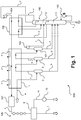
- FIG. 1 is a process not according to the invention for recovering hydrogen from a feed mixture containing hydrogen, methane and hydrocarbons having two carbon atoms which is lean or free of other hydrocarbons, illustrated in the form of a schematic process flow diagram and denoted overall by 300.
- the feed mixture containing hydrogen, methane and hydrocarbons having two carbon atoms and is low or free of other components is in the example shown in the form of a current a warm side of a heat exchanger 1, which, contrary to the illustrated example in the form of several heat exchangers, heat exchanger sections or Blocks may be formed, fed.
- the heat exchanger 1 can be operated for example with C2 refrigerants such as ethylene in the form of the currents x, y and z, wherein the current x, for example at a temperature of -57 ° C, the current y, for example at a temperature of -80 ° C and the current z is provided, for example, at a temperature of -100 ° C.
- C2 refrigerants such as ethylene in the form of the currents x, y and z, wherein the current x, for example at a temperature of -57 ° C, the current y, for example at a temperature of -80 ° C and the current z is provided, for example, at a temperature of -100 ° C.
- the flow a After removal from the heat exchanger 1 at an intermediate temperature level, the flow a is fed into a first separation tank 2. Due to the Abkühkung in the heat exchanger 1, a liquid condensate separates in the first separation vessel 2, which can be removed in the form of a liquid condensate stream b. Uncondensed fluid of the flow a is again passed through the heat exchanger 1 in the form of the flow c, where it is further cooled and finally fed into a second separation tank 3. Also the second Separation tank 3, a liquid condensate stream, here denoted by d, and a gaseous stream, here denoted by e, taken. The stream e is cooled again in the heat exchanger 1 and then fed to a third separating vessel, here denoted by 101.
- the demethanizer section 111 is operated with a bottom evaporator 113 in which, for example, ethylene can be used as the heating medium.
- a stream f may be withdrawn which contains predominantly hydrocarbons having two carbon atoms and is lean or free of other components.
- a stream s is withdrawn, liquefied in another heat exchanger 102 and fed as reflux to the absorption section 112.
- a stream t is further fed as reflux, which was taken from the third separating vessel 101 in a gaseous state and expanded in a turboexpander 103.
- hydrocarbons having two carbon atoms remaining from the stream t and not transferred to the liquid phase and thus into the stream r in the third separating vessel 101 can be separated off.
- a current u is also used, which is taken off the head from the absorption section 112, likewise liquefied in the heat exchanger 102 and subsequently fed into an upper region of the separation unit 110.
- a hydrogen-rich product stream I and a so-called tail gas stream m are obtained from the stream v.
- the tail gas stream m which advantageously contains substantially all the methane of the streams a and v and smaller amounts of hydrogen, is compressed in a compressor 10 to a suitable pressure, for example to a pressure required for use in a furnace, and also submitted.
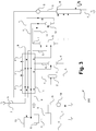
- FIG. 1 illustrates a method according to one embodiment of the invention in the form of a schematic process flow diagram and denoted overall by 100.
- Illustrated methods 300 are used in the method 100 described in U.S. Pat FIG. 2 is illustrated, only two separation tanks 2 and 3 used.
- the current e withdrawn in gaseous form from the head of the second separation vessel 3 is fed here into a separation unit designated by 5, the operation of which will be explained below.
- Illustrated method 100 transfers the liquid condensate streams b and d into a corresponding separation unit, which is designated here by 4.
- the separation unit 110 according to the in FIG. 1 illustrated method 300 is in the separation unit 4 according to the in FIG. 2 illustrated method 100 to a pure distillation column, ie functionally around a Demethanizerabrough 111 of the separation unit 110th appropriate apparatus.
- a sump evaporator of the separation unit 4 may, like the sump verifier 113, of the separation unit 110 according to the method 300 described in US Pat FIG. 1 is shown, for example, be heated with ethylene.
- a corresponding stream f is withdrawn from the bottom of the separation unit 4, which contains predominantly or exclusively hydrocarbons having two carbon atoms.
- a current denoted by g is withdrawn, compressed in a gaseous state in a compressor 6 and then cooled in the heat exchanger 1.
- the fluid of the flow g which is present upstream of the compressor 6 at the pressure of the low-pressure demethanizer 4 and would not be liquefied at this pressure at the temperatures of the heat exchanger 1, reaches a pressure sufficient for liquefaction. Therefore, unlike the prior art, no relaxation of large volumes of fluid is required to provide temperature levels than those that the heat exchanger 1 is capable of providing. With regard to the advantages thereof, reference is made to the above explanations.
- stream a has comparatively small amounts of methane and comparatively large amounts of hydrogen provided that stream a is derived, for example, from steam splitting of predominantly ethane-containing feeds, so stream g contains comparatively large amounts of ethylene but comparatively little methane , In the exclusive feed of the current g in the separation unit 5, therefore, the risk of comparatively high losses of ethylene in a top stream i, which is taken from the head of the separation unit 5.
- FIG. 2 a return flow h abandoned, which has predominantly or exclusively ethane and was cooled in the heat exchanger 1 to the third temperature level.
- a corresponding current h can, for example, be taken from a C2 splitter to which the current f is supplied, or at the current h it can at least partially be externally supplied ethane.
- the Current h if it is not already present at a sufficient pressure for use in the separation unit 5, is pressure-increased by means of a pump 7.
- the ethylene of the stream g which at least partially passes into the gas phase in the separation unit 5, can be backwashed, so that ethylene losses in the stream i are reduced.
- the current i is thus still mainly or exclusively of methane and hydrogen. It is heated in the heat exchanger 1 and subjected to heating in a unit 8 to about 20 to 25 ° C without repressurization. The stream i is then fed to the pressure swing adsorption 9, in which the already described with reference to the method 300, which in FIG. 1 illustrated, currents I and m are formed.
- FIG. 2 illustrated method 100 proves to be particularly advantageous because here, in contrast to the recompression of the stream v, as according to the method 300, the in FIG. 1 is illustrated, must be done, such recompression is not required. This is due, in particular, to the fact that there is no need for additional cooling to liquefy a top stream g of the separation unit 4 (in contrast to the flows s and u of the method 300, which is described in US Pat FIG. 1 is illustrated).
- the current i is according to FIG. 2 already at a pressure that is suitable for use in pressure swing adsorption 9.
- the top stream of the separation unit 4 only has to be compressed in a relatively small amount by means of the (cold) compressor 6. Its operation proves to be significantly cheaper, because in this much smaller amounts are to be compacted.
- a further absorption medium is provided, which likewise requires no additional cold for its production in the method 100.
- a method 100 in which a stream h is used, which contains predominantly or exclusively ethane, it may also be sufficient in certain cases, only feed the currents e and g in the separation unit 5. This is particularly the case when the stream a has sufficient amounts of methane, which are sufficient to a backwashing of ethylene in the separation unit 5. This is particularly the case when the stream a from a vapor separation of liquid inserts or gaseous inserts such as propane or combined inserts (from, for example, naphtha, ethane and LPG). In this case, the methane content of the stream g is sufficient to cause sufficient backwash of hydrocarbon having two carbon atoms in the separation unit 5 even without the additional use of the stream h.
- FIG. 3 is a variant of in FIG. 2 illustrated method 100 and generally designated 200. It is a method according to another embodiment of the invention.
- the current i is passed through a further heat exchanger 11 and cooled there to a temperature of for example about -152 ° C. Subsequently, the current i, which was at least partially liquefied by the cooling in the further heat exchanger 11, transferred to a separation vessel 12, from the bottom of which a methane on and depleted of hydrogen stream o and from the head of a hydrogen on and Methane depleted stream n is removed. Both streams are heated in the heat exchanger 1, wherein the stream n is treated as the stream i in the method 100, which in FIG. 2 is illustrated.
- the stream o is further cooled after heating in the heat exchanger 1 in a unit 13 and combined downstream of the compressor 10 with the current m.
Landscapes
- Chemical & Material Sciences (AREA)
- Engineering & Computer Science (AREA)
- Organic Chemistry (AREA)
- General Engineering & Computer Science (AREA)
- Physics & Mathematics (AREA)
- Thermal Sciences (AREA)
- Mechanical Engineering (AREA)
- Oil, Petroleum & Natural Gas (AREA)
- Chemical Kinetics & Catalysis (AREA)
- General Chemical & Material Sciences (AREA)
- Analytical Chemistry (AREA)
- Inorganic Chemistry (AREA)
- Combustion & Propulsion (AREA)
- Organic Low-Molecular-Weight Compounds And Preparation Thereof (AREA)
- Separation By Low-Temperature Treatments (AREA)
- Hydrogen, Water And Hydrids (AREA)
- Separation Of Gases By Adsorption (AREA)
Claims (15)
- Procédé (100, 200) de production d'hydrogène à partir d'un mélange de charge contenant de l'hydrogène, du méthane et des hydrocarbures avec deux atomes de carbone et peu ou pas d'autres hydrocarbures, dans lequel- on refroidit le fluide du mélange de charge à un premier niveau de pression d'un premier niveau de température à un deuxième niveau de température, dans lequel on sépare un ou plusieurs condensat(s) hors du fluide du mélange de charge en laissant subsister un gaz résiduel,- on refroidit de nouveau le fluide du gaz résiduel à un troisième niveau de température et on le soumet à une absorption à contre-courant avec obtention d'un gaz de tête riche en hydrogène et en méthane et d'un liquide de fond,- on chauffe le fluide du gaz de tête et on le soumet au premier niveau de pression à une adsorption à pression alternée (9) avec formation d'un courant de produit riche en hydrogène et contenant peu ou pas de méthane, et- on détend le fluide du ou des condensat (s) et/ou du liquide de fond du premier niveau de pression à un deuxième niveau de pression et on l'envoie au deuxième niveau de pression à un méthaniseur à basse pression,caractérisé en ce que l'on effectue l'absorption à contre-courant au premier niveau de pression avec utilisation de fluide, que l'on prélève au méthaniseur à basse pression au deuxième niveau de pression, que l'on comprime à l'état gazeux au premier niveau de pression et que l'on refroidit au troisième niveau de température.
- Procédé (100, 200) selon la revendication 1, dans lequel le mélange de charge contient 55 à 90, en particulier 60 à 90, pour cent molaires de méthane.
- Procédé (100, 200) selon la revendication 2, dans lequel le fluide prélevé au méthaniseur à basse pression et utilisé pour l'absorption à contre-courant contient principalement ou exclusivement du méthane et est utilisé comme retour liquide lors de l'absorption à contre-courant.
- Procédé (100, 200) selon la revendication 1, dans lequel le mélange de charge contient 30 à 55, en particulier 30 à 40, pour cent molaires de méthane.
- Procédé (100, 200) selon la revendication 4, dans lequel le fluide prélevé au méthaniseur à basse pression et utilisé pour l'absorption à contre-courant contient du méthane et de l'éthylène et est au moins en partie débarrassé de l'éthylène lors de l'absorption à contre-courant.
- Procédé (100, 200) selon la revendication 4, dans lequel on utilise lors de l'absorption à contre-courant un retour riche en éthane, au moyen duquel des hydrocarbures avec deux atomes d'hydrogène sont lavés aussi bien hors du fluide du gaz résiduel que hors du fluide prélevé au méthaniseur à basse pression et utilisé lors de l'absorption à contre-courant.
- Procédé (100, 200) selon la revendication 6, dans lequel on effectue l'absorption à contre-courant en utilisant une unité de séparation en deux parties avec une première section d'absorption et une seconde section d'absorption, dans lequel on introduit le fluide du gaz résiduel dans une région inférieure de la première section d'absorption et le fluide prélevé au méthaniseur à basse pression dans une région supérieure de la première section d'absorption, dans lequel on transfère un gaz d'une région supérieure de la première section d'absorption à une région inférieure de la seconde section d'absorption et on introduit le retour riche en éthane dans une région supérieure de la seconde section d'absorption.
- Procédé (100, 200) selon la revendication 7, dans lequel l'unité de séparation en deux parties est formée par une colonne d'absorption réalisée en deux parties (5), dans laquelle la première section d'absorption est disposée en dessous de la seconde section d'absorption dans une enveloppe extérieure commune.
- Procédé (100, 200) selon l'une quelconque des revendications précédentes, dans lequel on enrichit en hydrogène et on appauvrit en méthane le fluide du gaz résiduel avant l'adsorption à pression alternée (9).
- Procédé (100, 200) selon la revendication 9, dans lequel on enrichit en hydrogène et on appauvrit en méthane le fluide du gaz résiduel par un nouveau refroidissement et une nouvelle séparation d'un liquide contenant plus de méthane que d'hydrogène à partir du fluide du gaz résiduel.
- Procédé (100, 200) selon l'une quelconque des revendications précédentes, dans lequel le premier niveau de température se situe à -35°C à -57°C et/ou le deuxième niveau de température se situe à -60°C à -80°C et/ou le troisième niveau de température se situe à -95°C à - 100°C, en particulier à -97°C à -99°C.
- Procédé (100, 200) selon l'une quelconque des revendications précédentes, dans lequel le premier niveau de pression se situe à 20 à 35 bar, en particulier à 27 à 29 bar, et/ou le deuxième niveau de pression se situe à 10 à 25 bar, en particulier à 12 à 15 bar.
- Installation de production d'hydrogène à partir d'un mélange de charge contenant de l'hydrogène, du méthane et des hydrocarbures avec deux atomes de carbone et peu ou pas d'autres hydrocarbures, dotée de moyens qui sont conçus pour- refroidir le fluide du mélange de charge à un premier niveau de pression d'un premier niveau de température à un deuxième niveau de température, de telle manière qu'un ou plusieurs condensat(s) soit/soient séparé(s) hors du fluide du mélange de charge en laissant subsister un gaz résiduel,- refroidir de nouveau le fluide du gaz résiduel à un troisième niveau de température et le soumettre à une absorption à contre-courant avec obtention d'un gaz de tête riche en hydrogène et en méthane et d'un liquide de fond,- chauffer le fluide du gaz de tête et le soumettre au premier niveau de pression à une adsorption à pression alternée (9) avec formation d'un courant de produit riche en hydrogène et contenant peu ou pas de méthane, et- détendre le fluide du ou des condensat (s) et/ou du liquide de fond du premier niveau de pression à un deuxième niveau de pression et l'envoyer au deuxième niveau de pression à un méthaniseur à basse pression,caractérisé par des moyens, qui sont conçus pour effectuer l'absorption à contre-courant au premier niveau de pression en utilisant un fluide, que l'on prélève au méthaniseur à basse pression au deuxième niveau de pression, que l'on comprime à l'état gazeux au premier niveau de pression et que l'on refroidit au troisième niveau de température.
- Installation selon la revendication 13, qui présente pour effectuer l'absorption à contre-courant une unité de séparation en deux parties avec une première section d'absorption et une seconde section d'absorption, dans laquelle il est prévu des moyens qui sont conçus pour introduire le fluide du gaz résiduel dans une région inférieure de la première section d'absorption et le fluide prélevé au méthaniseur à basse pression dans une région supérieure de la première section d'absorption, transférer du gaz d'une région supérieure de la première section d'absorption à une région inférieure de la seconde section d'absorption, et d'introduire un retour riche en éthane dans une région supérieure de la seconde section d'absorption.
- Installation selon une revendication 13 ou 14, qui est conçue pour la mise en oeuvre d'un procédé (100, 200) selon l'une quelconque des revendications 1 à 12.
Applications Claiming Priority (2)
| Application Number | Priority Date | Filing Date | Title |
|---|---|---|---|
| EP15174308 | 2015-06-29 | ||
| PCT/EP2016/065197 WO2017001514A1 (fr) | 2015-06-29 | 2016-06-29 | Procédé et installation pour récupérer de l'hydrogène à partir d'un mélange de charge contenant de l'hydrogène et des hydrocarbures |
Publications (2)
| Publication Number | Publication Date |
|---|---|
| EP3313779A1 EP3313779A1 (fr) | 2018-05-02 |
| EP3313779B1 true EP3313779B1 (fr) | 2019-04-24 |
Family
ID=53773193
Family Applications (1)
| Application Number | Title | Priority Date | Filing Date |
|---|---|---|---|
| EP16734313.6A Not-in-force EP3313779B1 (fr) | 2015-06-29 | 2016-06-29 | Procede et installation de production d'hydrogene a partir un melange de charge contenant un hydrogene et des hydrocarbures |
Country Status (9)
| Country | Link |
|---|---|
| US (1) | US10464810B2 (fr) |
| EP (1) | EP3313779B1 (fr) |
| AU (1) | AU2016286853B2 (fr) |
| BR (1) | BR112017028626B1 (fr) |
| CA (1) | CA2990309C (fr) |
| EA (1) | EA032725B1 (fr) |
| MY (1) | MY182862A (fr) |
| WO (1) | WO2017001514A1 (fr) |
| ZA (1) | ZA201800599B (fr) |
Families Citing this family (6)
| Publication number | Priority date | Publication date | Assignee | Title |
|---|---|---|---|---|
| EP3282212A1 (fr) * | 2016-08-12 | 2018-02-14 | Linde Aktiengesellschaft | Procede de production d'un produit de separation contenant principalement des hydrocarbures a deux atomes de carbone |
| EP3424582A1 (fr) * | 2017-07-06 | 2019-01-09 | Linde Aktiengesellschaft | Procédé et installation de traitement de séparation d'un mélange de départ |
| GB2581519A (en) * | 2019-02-22 | 2020-08-26 | Linde Ag | Process to remove benzene and other heavies for the prevention of freezing in cryogenic gas separations |
| US12533626B2 (en) * | 2021-09-09 | 2026-01-27 | ColdStream Energy IP, LLC | Portable pressure swing adsorption system and method for fuel gas conditioning |
| EP4384301A4 (fr) * | 2021-09-09 | 2025-11-26 | Coldstream Energy Ip Llc | Procédé et système d'adsorption modulée en pression portable pour traitement de gaz à faible débit |
| EP4411296A1 (fr) | 2023-02-02 | 2024-08-07 | Linde GmbH | Procédé et appareil de production d'une fraction d'hydrogène à l'aide d'une charge de séparation |
Family Cites Families (7)
| Publication number | Priority date | Publication date | Assignee | Title |
|---|---|---|---|---|
| FR2463758A1 (fr) * | 1979-08-23 | 1981-02-27 | Shirokov Vasily | Procede d'isolement des composants d'un melange d'hydrocarbures gazeux et installation pour sa mise en oeuvre |
| US4270940A (en) * | 1979-11-09 | 1981-06-02 | Air Products And Chemicals, Inc. | Recovery of C2 hydrocarbons from demethanizer overhead |
| US5546764A (en) * | 1995-03-03 | 1996-08-20 | Advanced Extraction Technologies, Inc. | Absorption process for recovering ethylene and hydrogen from refinery and petrochemical plant off-gases |
| US5979177A (en) * | 1998-01-06 | 1999-11-09 | Abb Lummus Global Inc. | Ethylene plant refrigeration system |
| US6560989B1 (en) * | 2002-06-07 | 2003-05-13 | Air Products And Chemicals, Inc. | Separation of hydrogen-hydrocarbon gas mixtures using closed-loop gas expander refrigeration |
| US20120151962A1 (en) * | 2010-12-20 | 2012-06-21 | L'air Liquide Societe Anonyme Pour L'etude Et L'exploitation Des Procedes Georges Claude | Ethylene Recovery From Off-Gas |
| CN103449950B (zh) * | 2012-11-19 | 2015-04-01 | 中国寰球工程公司 | 用贫液效应在脱甲烷过程中回收尾气中乙烯的方法及系统 |
-
2016
- 2016-06-29 BR BR112017028626-2A patent/BR112017028626B1/pt active IP Right Grant
- 2016-06-29 EP EP16734313.6A patent/EP3313779B1/fr not_active Not-in-force
- 2016-06-29 EA EA201890057A patent/EA032725B1/ru not_active IP Right Cessation
- 2016-06-29 MY MYPI2017001952A patent/MY182862A/en unknown
- 2016-06-29 US US15/741,187 patent/US10464810B2/en active Active
- 2016-06-29 CA CA2990309A patent/CA2990309C/fr active Active
- 2016-06-29 AU AU2016286853A patent/AU2016286853B2/en not_active Ceased
- 2016-06-29 WO PCT/EP2016/065197 patent/WO2017001514A1/fr not_active Ceased
-
2018
- 2018-01-29 ZA ZA201800599A patent/ZA201800599B/en unknown
Non-Patent Citations (1)
| Title |
|---|
| None * |
Also Published As
| Publication number | Publication date |
|---|---|
| AU2016286853B2 (en) | 2020-05-21 |
| ZA201800599B (en) | 2019-10-30 |
| US20180186632A1 (en) | 2018-07-05 |
| AU2016286853A1 (en) | 2018-01-25 |
| MY182862A (en) | 2021-02-05 |
| BR112017028626A2 (pt) | 2018-09-04 |
| BR112017028626B1 (pt) | 2023-02-14 |
| EP3313779A1 (fr) | 2018-05-02 |
| EA032725B1 (ru) | 2019-07-31 |
| CA2990309A1 (fr) | 2017-01-05 |
| EA201890057A1 (ru) | 2018-07-31 |
| WO2017001514A1 (fr) | 2017-01-05 |
| US10464810B2 (en) | 2019-11-05 |
| CA2990309C (fr) | 2023-10-03 |
Similar Documents
| Publication | Publication Date | Title |
|---|---|---|
| EP3029019B1 (fr) | Procédé de fabrication d'hydrocarbures | |
| EP3313779B1 (fr) | Procede et installation de production d'hydrogene a partir un melange de charge contenant un hydrogene et des hydrocarbures | |
| DE69618736T2 (de) | Verfahren und Vorrichtung zur Verflüssigung und Behandlung von Erdgas | |
| EP3775735B1 (fr) | Procédé et une installation de séparation d'un mélange d'hydrocarbures | |
| EP3092052B1 (fr) | Procédé de séparation d'un mélange d'hydrocarbures contenant de l'hydrogène, dispositif de séparation et installation d'oléfine | |
| EP3652138B1 (fr) | Procédé et installation de fabrication de propylène par combinaison de déshydrogénation de propane et procédé de vapocraquage avec stages de pre-séparation dans les deux procédés pour éliminer hydrogène et méthane | |
| EP3456703A1 (fr) | Procédé et installation de fabrication d'éthylène | |
| EP3648866B1 (fr) | Procédé et installation de traitement de séparation d'un mélange de départ | |
| EP3029402A1 (fr) | Procédé et système de traitement technique de séparation d'un courant de charge | |
| WO2017125438A1 (fr) | Procédé de traitement par séparation d'un mélange gazeux | |
| EP3497391B1 (fr) | Procede de production d'un produit de separation contenant principalement des hydrocarbures a deux atomes de carbone | |
| WO2017037018A1 (fr) | Procédé et installation de traitement par séparation d'un mélange de départ | |
| EP3029017A1 (fr) | Procédé et système de fabrication d'hydrocarbures | |
| WO2017125435A1 (fr) | Procédé de production d'éthylène à partir de méthane | |
| EP3940042A1 (fr) | Procédé et installation d'extraction d'hydrocarbures | |
| EP3775734A1 (fr) | Procédé de séparation d'un mélange de composants et équipement de séparation | |
| EP3241819A1 (fr) | Procede de de-methanisation et de-methaniseur | |
| DE102016001911A1 (de) | Kombinationsprozess und Anlage zur Herstellung von Synthesegas und von Olefinen | |
| WO2017125432A1 (fr) | Processus de production d'éthylène à partir de méthane | |
| EP4420753A1 (fr) | Procédé et installation pour fournir une fraction d'hydrogène | |
| DE102019115395A1 (de) | Verfahren und Anlage zur trenntechnischen Bearbeitung eines Gasgemischs | |
| DE102005003499A1 (de) | Verfahren und Vorrichtung zur Trennung von Stoffgemischen |
Legal Events
| Date | Code | Title | Description |
|---|---|---|---|
| STAA | Information on the status of an ep patent application or granted ep patent |
Free format text: STATUS: THE INTERNATIONAL PUBLICATION HAS BEEN MADE |
|
| PUAI | Public reference made under article 153(3) epc to a published international application that has entered the european phase |
Free format text: ORIGINAL CODE: 0009012 |
|
| STAA | Information on the status of an ep patent application or granted ep patent |
Free format text: STATUS: REQUEST FOR EXAMINATION WAS MADE |
|
| 17P | Request for examination filed |
Effective date: 20180129 |
|
| AK | Designated contracting states |
Kind code of ref document: A1 Designated state(s): AL AT BE BG CH CY CZ DE DK EE ES FI FR GB GR HR HU IE IS IT LI LT LU LV MC MK MT NL NO PL PT RO RS SE SI SK SM TR |
|
| AX | Request for extension of the european patent |
Extension state: BA ME |
|
| DAV | Request for validation of the european patent (deleted) | ||
| DAX | Request for extension of the european patent (deleted) | ||
| GRAP | Despatch of communication of intention to grant a patent |
Free format text: ORIGINAL CODE: EPIDOSNIGR1 |
|
| STAA | Information on the status of an ep patent application or granted ep patent |
Free format text: STATUS: GRANT OF PATENT IS INTENDED |
|
| INTG | Intention to grant announced |
Effective date: 20181109 |
|
| GRAS | Grant fee paid |
Free format text: ORIGINAL CODE: EPIDOSNIGR3 |
|
| GRAA | (expected) grant |
Free format text: ORIGINAL CODE: 0009210 |
|
| STAA | Information on the status of an ep patent application or granted ep patent |
Free format text: STATUS: THE PATENT HAS BEEN GRANTED |
|
| AK | Designated contracting states |
Kind code of ref document: B1 Designated state(s): AL AT BE BG CH CY CZ DE DK EE ES FI FR GB GR HR HU IE IS IT LI LT LU LV MC MK MT NL NO PL PT RO RS SE SI SK SM TR |
|
| REG | Reference to a national code |
Ref country code: GB Ref legal event code: FG4D Free format text: NOT ENGLISH |
|
| REG | Reference to a national code |
Ref country code: CH Ref legal event code: EP |
|
| REG | Reference to a national code |
Ref country code: DE Ref legal event code: R096 Ref document number: 502016004355 Country of ref document: DE |
|
| REG | Reference to a national code |
Ref country code: AT Ref legal event code: REF Ref document number: 1123911 Country of ref document: AT Kind code of ref document: T Effective date: 20190515 Ref country code: IE Ref legal event code: FG4D Free format text: LANGUAGE OF EP DOCUMENT: GERMAN |
|
| REG | Reference to a national code |
Ref country code: NL Ref legal event code: MP Effective date: 20190424 |
|
| REG | Reference to a national code |
Ref country code: LT Ref legal event code: MG4D |
|
| PG25 | Lapsed in a contracting state [announced via postgrant information from national office to epo] |
Ref country code: NL Free format text: LAPSE BECAUSE OF FAILURE TO SUBMIT A TRANSLATION OF THE DESCRIPTION OR TO PAY THE FEE WITHIN THE PRESCRIBED TIME-LIMIT Effective date: 20190424 |
|
| REG | Reference to a national code |
Ref country code: NO Ref legal event code: T2 Effective date: 20190424 |
|
| PG25 | Lapsed in a contracting state [announced via postgrant information from national office to epo] |
Ref country code: AL Free format text: LAPSE BECAUSE OF FAILURE TO SUBMIT A TRANSLATION OF THE DESCRIPTION OR TO PAY THE FEE WITHIN THE PRESCRIBED TIME-LIMIT Effective date: 20190424 Ref country code: PT Free format text: LAPSE BECAUSE OF FAILURE TO SUBMIT A TRANSLATION OF THE DESCRIPTION OR TO PAY THE FEE WITHIN THE PRESCRIBED TIME-LIMIT Effective date: 20190824 Ref country code: ES Free format text: LAPSE BECAUSE OF FAILURE TO SUBMIT A TRANSLATION OF THE DESCRIPTION OR TO PAY THE FEE WITHIN THE PRESCRIBED TIME-LIMIT Effective date: 20190424 Ref country code: SE Free format text: LAPSE BECAUSE OF FAILURE TO SUBMIT A TRANSLATION OF THE DESCRIPTION OR TO PAY THE FEE WITHIN THE PRESCRIBED TIME-LIMIT Effective date: 20190424 Ref country code: HR Free format text: LAPSE BECAUSE OF FAILURE TO SUBMIT A TRANSLATION OF THE DESCRIPTION OR TO PAY THE FEE WITHIN THE PRESCRIBED TIME-LIMIT Effective date: 20190424 Ref country code: FI Free format text: LAPSE BECAUSE OF FAILURE TO SUBMIT A TRANSLATION OF THE DESCRIPTION OR TO PAY THE FEE WITHIN THE PRESCRIBED TIME-LIMIT Effective date: 20190424 Ref country code: LT Free format text: LAPSE BECAUSE OF FAILURE TO SUBMIT A TRANSLATION OF THE DESCRIPTION OR TO PAY THE FEE WITHIN THE PRESCRIBED TIME-LIMIT Effective date: 20190424 |
|
| PG25 | Lapsed in a contracting state [announced via postgrant information from national office to epo] |
Ref country code: RS Free format text: LAPSE BECAUSE OF FAILURE TO SUBMIT A TRANSLATION OF THE DESCRIPTION OR TO PAY THE FEE WITHIN THE PRESCRIBED TIME-LIMIT Effective date: 20190424 Ref country code: LV Free format text: LAPSE BECAUSE OF FAILURE TO SUBMIT A TRANSLATION OF THE DESCRIPTION OR TO PAY THE FEE WITHIN THE PRESCRIBED TIME-LIMIT Effective date: 20190424 Ref country code: PL Free format text: LAPSE BECAUSE OF FAILURE TO SUBMIT A TRANSLATION OF THE DESCRIPTION OR TO PAY THE FEE WITHIN THE PRESCRIBED TIME-LIMIT Effective date: 20190424 Ref country code: BG Free format text: LAPSE BECAUSE OF FAILURE TO SUBMIT A TRANSLATION OF THE DESCRIPTION OR TO PAY THE FEE WITHIN THE PRESCRIBED TIME-LIMIT Effective date: 20190724 Ref country code: GR Free format text: LAPSE BECAUSE OF FAILURE TO SUBMIT A TRANSLATION OF THE DESCRIPTION OR TO PAY THE FEE WITHIN THE PRESCRIBED TIME-LIMIT Effective date: 20190725 |
|
| PG25 | Lapsed in a contracting state [announced via postgrant information from national office to epo] |
Ref country code: IS Free format text: LAPSE BECAUSE OF FAILURE TO SUBMIT A TRANSLATION OF THE DESCRIPTION OR TO PAY THE FEE WITHIN THE PRESCRIBED TIME-LIMIT Effective date: 20190824 |
|
| REG | Reference to a national code |
Ref country code: DE Ref legal event code: R097 Ref document number: 502016004355 Country of ref document: DE |
|
| PG25 | Lapsed in a contracting state [announced via postgrant information from national office to epo] |
Ref country code: MC Free format text: LAPSE BECAUSE OF FAILURE TO SUBMIT A TRANSLATION OF THE DESCRIPTION OR TO PAY THE FEE WITHIN THE PRESCRIBED TIME-LIMIT Effective date: 20190424 Ref country code: DK Free format text: LAPSE BECAUSE OF FAILURE TO SUBMIT A TRANSLATION OF THE DESCRIPTION OR TO PAY THE FEE WITHIN THE PRESCRIBED TIME-LIMIT Effective date: 20190424 Ref country code: SK Free format text: LAPSE BECAUSE OF FAILURE TO SUBMIT A TRANSLATION OF THE DESCRIPTION OR TO PAY THE FEE WITHIN THE PRESCRIBED TIME-LIMIT Effective date: 20190424 Ref country code: EE Free format text: LAPSE BECAUSE OF FAILURE TO SUBMIT A TRANSLATION OF THE DESCRIPTION OR TO PAY THE FEE WITHIN THE PRESCRIBED TIME-LIMIT Effective date: 20190424 Ref country code: CZ Free format text: LAPSE BECAUSE OF FAILURE TO SUBMIT A TRANSLATION OF THE DESCRIPTION OR TO PAY THE FEE WITHIN THE PRESCRIBED TIME-LIMIT Effective date: 20190424 Ref country code: RO Free format text: LAPSE BECAUSE OF FAILURE TO SUBMIT A TRANSLATION OF THE DESCRIPTION OR TO PAY THE FEE WITHIN THE PRESCRIBED TIME-LIMIT Effective date: 20190424 |
|
| REG | Reference to a national code |
Ref country code: CH Ref legal event code: PL |
|
| PG25 | Lapsed in a contracting state [announced via postgrant information from national office to epo] |
Ref country code: IT Free format text: LAPSE BECAUSE OF FAILURE TO SUBMIT A TRANSLATION OF THE DESCRIPTION OR TO PAY THE FEE WITHIN THE PRESCRIBED TIME-LIMIT Effective date: 20190424 Ref country code: SM Free format text: LAPSE BECAUSE OF FAILURE TO SUBMIT A TRANSLATION OF THE DESCRIPTION OR TO PAY THE FEE WITHIN THE PRESCRIBED TIME-LIMIT Effective date: 20190424 |
|
| PLBE | No opposition filed within time limit |
Free format text: ORIGINAL CODE: 0009261 |
|
| STAA | Information on the status of an ep patent application or granted ep patent |
Free format text: STATUS: NO OPPOSITION FILED WITHIN TIME LIMIT |
|
| REG | Reference to a national code |
Ref country code: BE Ref legal event code: MM Effective date: 20190630 |
|
| PG25 | Lapsed in a contracting state [announced via postgrant information from national office to epo] |
Ref country code: TR Free format text: LAPSE BECAUSE OF FAILURE TO SUBMIT A TRANSLATION OF THE DESCRIPTION OR TO PAY THE FEE WITHIN THE PRESCRIBED TIME-LIMIT Effective date: 20190424 |
|
| 26N | No opposition filed |
Effective date: 20200127 |
|
| PG25 | Lapsed in a contracting state [announced via postgrant information from national office to epo] |
Ref country code: IE Free format text: LAPSE BECAUSE OF NON-PAYMENT OF DUE FEES Effective date: 20190629 |
|
| PG25 | Lapsed in a contracting state [announced via postgrant information from national office to epo] |
Ref country code: LU Free format text: LAPSE BECAUSE OF NON-PAYMENT OF DUE FEES Effective date: 20190629 Ref country code: BE Free format text: LAPSE BECAUSE OF NON-PAYMENT OF DUE FEES Effective date: 20190630 Ref country code: CH Free format text: LAPSE BECAUSE OF NON-PAYMENT OF DUE FEES Effective date: 20190630 Ref country code: SI Free format text: LAPSE BECAUSE OF FAILURE TO SUBMIT A TRANSLATION OF THE DESCRIPTION OR TO PAY THE FEE WITHIN THE PRESCRIBED TIME-LIMIT Effective date: 20190424 Ref country code: LI Free format text: LAPSE BECAUSE OF NON-PAYMENT OF DUE FEES Effective date: 20190630 |
|
| PG25 | Lapsed in a contracting state [announced via postgrant information from national office to epo] |
Ref country code: FR Free format text: LAPSE BECAUSE OF NON-PAYMENT OF DUE FEES Effective date: 20190630 |
|
| REG | Reference to a national code |
Ref country code: DE Ref legal event code: R081 Ref document number: 502016004355 Country of ref document: DE Owner name: LINDE GMBH, DE Free format text: FORMER OWNER: LINDE AG, 80331 MUENCHEN, DE |
|
| PG25 | Lapsed in a contracting state [announced via postgrant information from national office to epo] |
Ref country code: CY Free format text: LAPSE BECAUSE OF FAILURE TO SUBMIT A TRANSLATION OF THE DESCRIPTION OR TO PAY THE FEE WITHIN THE PRESCRIBED TIME-LIMIT Effective date: 20190424 |
|
| PG25 | Lapsed in a contracting state [announced via postgrant information from national office to epo] |
Ref country code: MT Free format text: LAPSE BECAUSE OF FAILURE TO SUBMIT A TRANSLATION OF THE DESCRIPTION OR TO PAY THE FEE WITHIN THE PRESCRIBED TIME-LIMIT Effective date: 20190424 Ref country code: HU Free format text: LAPSE BECAUSE OF FAILURE TO SUBMIT A TRANSLATION OF THE DESCRIPTION OR TO PAY THE FEE WITHIN THE PRESCRIBED TIME-LIMIT; INVALID AB INITIO Effective date: 20160629 |
|
| PG25 | Lapsed in a contracting state [announced via postgrant information from national office to epo] |
Ref country code: MK Free format text: LAPSE BECAUSE OF FAILURE TO SUBMIT A TRANSLATION OF THE DESCRIPTION OR TO PAY THE FEE WITHIN THE PRESCRIBED TIME-LIMIT Effective date: 20190424 |
|
| REG | Reference to a national code |
Ref country code: AT Ref legal event code: MM01 Ref document number: 1123911 Country of ref document: AT Kind code of ref document: T Effective date: 20210629 |
|
| PG25 | Lapsed in a contracting state [announced via postgrant information from national office to epo] |
Ref country code: AT Free format text: LAPSE BECAUSE OF NON-PAYMENT OF DUE FEES Effective date: 20210629 |
|
| PGFP | Annual fee paid to national office [announced via postgrant information from national office to epo] |
Ref country code: GB Payment date: 20240620 Year of fee payment: 9 |
|
| PGFP | Annual fee paid to national office [announced via postgrant information from national office to epo] |
Ref country code: DE Payment date: 20240617 Year of fee payment: 9 |
|
| PGFP | Annual fee paid to national office [announced via postgrant information from national office to epo] |
Ref country code: NO Payment date: 20240618 Year of fee payment: 9 |
|
| REG | Reference to a national code |
Ref country code: DE Ref legal event code: R119 Ref document number: 502016004355 Country of ref document: DE |
|
| GBPC | Gb: european patent ceased through non-payment of renewal fee |
Effective date: 20250629 |
|
| PG25 | Lapsed in a contracting state [announced via postgrant information from national office to epo] |
Ref country code: GB Free format text: LAPSE BECAUSE OF NON-PAYMENT OF DUE FEES Effective date: 20250629 |
|
| PG25 | Lapsed in a contracting state [announced via postgrant information from national office to epo] |
Ref country code: NO Free format text: LAPSE BECAUSE OF NON-PAYMENT OF DUE FEES Effective date: 20250630 Ref country code: DE Free format text: LAPSE BECAUSE OF NON-PAYMENT OF DUE FEES Effective date: 20260101 |