EP3314047B1 - Article textile à poche, système et son procédé de fabrication - Google Patents
Article textile à poche, système et son procédé de fabrication Download PDFInfo
- Publication number
- EP3314047B1 EP3314047B1 EP15747837.1A EP15747837A EP3314047B1 EP 3314047 B1 EP3314047 B1 EP 3314047B1 EP 15747837 A EP15747837 A EP 15747837A EP 3314047 B1 EP3314047 B1 EP 3314047B1
- Authority
- EP
- European Patent Office
- Prior art keywords
- panel
- elastic
- thread
- manufacturing
- free edge
- Prior art date
- Legal status (The legal status is an assumption and is not a legal conclusion. Google has not performed a legal analysis and makes no representation as to the accuracy of the status listed.)
- Active
Links
Images

Classifications
-
- D—TEXTILES; PAPER
- D04—BRAIDING; LACE-MAKING; KNITTING; TRIMMINGS; NON-WOVEN FABRICS
- D04B—KNITTING
- D04B1/00—Weft knitting processes for the production of fabrics or articles not dependent on the use of particular machines; Fabrics or articles defined by such processes
- D04B1/14—Other fabrics or articles characterised primarily by the use of particular thread materials
- D04B1/18—Other fabrics or articles characterised primarily by the use of particular thread materials elastic threads
-
- A—HUMAN NECESSITIES
- A61—MEDICAL OR VETERINARY SCIENCE; HYGIENE
- A61F—FILTERS IMPLANTABLE INTO BLOOD VESSELS; PROSTHESES; DEVICES PROVIDING PATENCY TO, OR PREVENTING COLLAPSING OF, TUBULAR STRUCTURES OF THE BODY, e.g. STENTS; ORTHOPAEDIC, NURSING OR CONTRACEPTIVE DEVICES; FOMENTATION; TREATMENT OR PROTECTION OF EYES OR EARS; BANDAGES, DRESSINGS OR ABSORBENT PADS; FIRST-AID KITS
- A61F13/00—Bandages or dressings; Absorbent pads
- A61F13/06—Bandages or dressings; Absorbent pads specially adapted for feet or legs; Corn-pads; Corn-rings
- A61F13/08—Elastic stockings; for contracting aneurisms
-
- D—TEXTILES; PAPER
- D10—INDEXING SCHEME ASSOCIATED WITH SUBLASSES OF SECTION D, RELATING TO TEXTILES
- D10B—INDEXING SCHEME ASSOCIATED WITH SUBLASSES OF SECTION D, RELATING TO TEXTILES
- D10B2501/00—Wearing apparel
- D10B2501/06—Details of garments
- D10B2501/061—Piped openings (pockets)
-
- D—TEXTILES; PAPER
- D10—INDEXING SCHEME ASSOCIATED WITH SUBLASSES OF SECTION D, RELATING TO TEXTILES
- D10B—INDEXING SCHEME ASSOCIATED WITH SUBLASSES OF SECTION D, RELATING TO TEXTILES
- D10B2509/00—Medical; Hygiene
- D10B2509/02—Bandages, dressings or absorbent pads
- D10B2509/028—Elastic support stockings or elastic bandages
Definitions
- the present invention relates to the general technical field of textile articles intended to surround a human or animal body segment, such as for example a joint, muscular or bone structure, in order to provide a therapeutic function (in particular of an orthopedic nature) and/or non-therapeutic function, for example a function of containment, compression, maintenance, stabilization, keeping warm or warming.
- a therapeutic function in particular of an orthopedic nature
- non-therapeutic function for example a function of containment, compression, maintenance, stabilization, keeping warm or warming.
- the present invention relates more specifically to a textile article comprising a first panel intended to surround a part of a human or animal body, said first panel being constituted by a first knit which is composed of stitches formed by at least a first thread and which includes an elastic weave to allow said article to elastically enclose said part of the human or animal body.
- the invention also relates to a method of manufacturing a textile article comprising a step of manufacturing a first panel, by knitting at least one first yarn with insertion of an elastic weave, said first panel being intended to elastically enclose a part of a human or animal body.
- orthoses it is known to use orthoses to surround a joint, muscular or bone structure of the human body, in order to obtain a therapeutic effect by an external mechanical action, such as a containment, compression or maintenance action, for example for the purposes of stabilizing or assisting the structure in question during a rehabilitation or convalescence phase.
- an external mechanical action such as a containment, compression or maintenance action
- orthoses each adapted to a specific body region (wrist orthosis, knee brace, elbow brace, ankle brace, dorso-lumbar belt, cervical collar, etc.).
- thermo-therapeutic compress generally referred to as a "hot/ cold gel pack"
- these known pocket orthoses are formed from a strip of elastic fabric intended to surround the affected part of the human body. On one side of this strip is added an elastane panel sewn at its periphery to the elastic strip to form the pocket, with an opening allowing a gel pack to be inserted and removed at will.
- pocket orthoses can indeed prove uncomfortable, due to the presence of the seams for attaching the elastane panel, and their manufacture is relatively complicated and expensive, due to the multiplicity of operations required and the different technical fabrics used. Furthermore, the presence of the elastane panel may be such as to locally affect the compression and containment properties of the elastic band. Furthermore, these known orthoses do not allow in practice an optimal heat exchange between the gel pack inserted in the pocket and the body area enclosed by the orthosis. The design and construction of these known orthoses is also not such as to optimally limit heat loss, so that part of the calories or frigories provided by the gel pack are likely to be dissipated to the outside, through the elastic band. Finally, with these known orthoses there is a risk that the gel pack may accidentally escape from the pocket, so that wearing these known orthoses may be incompatible with sports practice.
- the document FR-2 781 817 A1 discloses in summary a weft knit comprising a pocket obtained by a method consisting, in a first phase, in producing a first row of stitches with a thread which, in the pocket area, works with all the needles of the front needle bed and only with at least one needle out of two of the rear needle bed, leaving free needles, in a second phase, in placing the weft thread on the first row of stitches, in a third phase, in the pocket area, in taking, with a ratio of at least 1/2, a stitch from the rear needle bed to transfer it to a meshed needle of the front needle bed, and, in a fourth phase, in producing a second row of stitches whose thread works in the pocket area, with only the needles of the rear needle bed which did not work in the first phase.
- the present invention therefore aims to remedy the various drawbacks listed above, and to propose a new textile article intended to surround a part of a human or animal body which, while being equipped with a housing allowing an independent functional element to be accommodated (such as example a thermal compress), is particularly comfortable for the wearer, robust, aesthetic, and has controlled elastic extensibility properties.
- an independent functional element to be accommodated such as example a thermal compress
- Another object of the invention is to propose a new textile article intended to surround a part of a human or animal body which lends itself particularly well to industrial manufacture.
- Another object of the invention aims to propose a new textile article intended to surround a part of a human or animal body, the construction of which makes it possible to optimize the action of the independent functional element inserted in a housing with which said textile article is provided.
- Another object of the invention is to propose a new textile article intended to surround a part of a human or animal body, the construction of which is particularly simple and can be implemented in a mechanized manner using conventional industrial equipment.
- Another object of the invention is to propose a new textile article intended to surround a part of a human or animal body, which is provided with a housing designed to hold within it in a particularly effective manner an independent functional element, such as a thermal compress, without the risk of seeing said functional element unexpectedly escape from said housing.
- Another object of the invention aims to propose a new textile article intended to surround a part of a human or animal body, the manufacture of which is based on the implementation of particularly simple elementary operations.
- Another object of the invention aims to propose a new method of manufacturing a textile article intended to surround a part of a human or animal body, which makes it possible to obtain in a particularly simple, rapid and inexpensive manner a textile article which, while being provided with a housing capable of removably accommodating an independent functional element, is particularly comfortable and robust.
- Another object of the invention is to propose a new method of manufacturing a textile article intended to surround a part of a human or animal body, which can be easily automated.
- Another object of the invention aims to propose a new method of manufacturing a textile article intended to surround a part of a human or animal body, which is based on the implementation of simple elementary operations, from a minimum of different starting components.
- Another object of the invention is to propose a new method of manufacturing a textile article intended to surround a part of a human or animal body, which can be implemented in a mechanized manner using standard industrial equipment.
- a textile article comprising a first panel intended to surround a part of a human or animal body, said first panel being constituted by a first knit which is composed of stitches and which includes an elastic weave to allow said article to elastically enclose said part of the human or animal body, and comprising a second panel locally superimposed on said first panel and attached to the latter to form with said first panel a housing which is provided with an access opening in order to removably accommodate therein an independent functional element, said housing (6) constituting a pocket formed by a front panel and a rear panel (7) mutually attached at the periphery, said front panel being formed by said second panel (5), while said first panel (2) is formed by said rear panel (7) as well as by a main panel (8) which at least partly surrounds said rear panel (7), the stitches of said first knit which constitute said main panel (8) being formed by a first thread (3) as well as by a second thread (9), while the stitches of first knit fabric which constitute said back panel (7) are formed by said second
- the objects assigned to the invention are also achieved using a system comprising on the one hand a textile article according to the invention, and on the other hand an independent functional element intended to be received in a removable manner within the housing. of said textile article, said functional element being part of the following group: thermal compress, device for diffusing an active substance, such as for example an analgesic substance, variable volume compression device.
- a method of manufacturing a textile article comprising a step of manufacturing a first panel by knitting at least one first yarn with insertion of an elastic weft, said first panel intended to elastically enclose a part of a human or animal body, said method being characterized in that it comprises a step of manufacturing, by knitting said first thread, a second panel locally superimposed on said first panel and attached to the latter to form with said first panel a housing which is provided with an access opening in order to removably accommodate therein an independent functional element, said housing (6) constituting a pocket formed by a front panel and a rear panel (7) mutually attached at the periphery, said front panel being formed by said second panel (5), while said first panel (2) is formed by said rear panel (7) as well as by a main panel (8) which at least partly surrounds said rear panel (7), said manufacturing step (i) of said first panel (2) comprising: - an operation of manufacturing said main panel (8) by knitting said first thread (3) and a second thread (9), -
- the invention relates to a textile article 1 intended to surround a part of a human or animal body, for therapeutic or non-therapeutic purposes.
- the article textile 1 is an article for containing, compressing, maintaining or stabilizing a part of a human or animal body, which is formed for example by a joint, muscular or bone structure, in order to advantageously obtain a therapeutic (or preventive) effect by a mechanical action of enclosing the body segment concerned, whether for example in an acute traumatic phase, during a rehabilitation or convalescence process (for example post-traumatic), or to prevent a possible trauma or an illness.
- the textile article 1 according to the invention thus advantageously forms an orthosis, and in particular an orthopedic orthosis such as for example a wrist/thumb orthosis, a wrist/hand orthosis, a cervical collar, a lumbar belt, an elbow brace, a knee brace, etc.
- the invention is however not limited to a therapeutic textile article 1 intended to surround a part of a human or animal body in prevention or treatment of trauma, in particular orthopedic trauma.
- the textile article 1 may for example be designed to surround a part of a human or animal body for the prevention or treatment of ailments of rheumatic origin.
- the textile article 1 therefore advantageously consists of a textile article, preferably orthopedic, designed to surround a part of a human or animal body (for example forming part of the locomotor system) as part of a preventive or curative treatment of ailments of traumatic or rheumatic origin and associated pain.
- the invention is however not limited to a therapeutic article.
- the textile article 1 may for example constitute a textile article 1 of comfort, and be presented for example in the form of a “ heat belt ” intended to keep the part of the human or animal body concerned warm, without curative or preventive purpose, or for example in the form of a “ pregnancy belt ” intended to improve the comfort of the pregnant woman by supporting her abdomen.
- textile article 1 is therefore a therapeutic textile article (preventive or curative of ailments of traumatic or organic origin) and/or comfort, the primary effect of which is essentially based on elastic enveloping of the part of the human or animal body to be treated.
- the textile article 1 is designed to be worn by a human person, in order to surround a part of the body of the person in question. It It is however perfectly conceivable, according to a second variant, that the textile article 1 is designed to be worn by an animal, for example a horse, a dog, a cat, etc.
- the invention also relates to a method of manufacturing such a textile article 1, so that the following description is applicable indifferently to the article 1 itself but also to the corresponding manufacturing method, and vice versa.
- the textile article 1 comprises a first panel 2 intended to surround said part of the human body.
- the first panel 2 advantageously has a substantially tubular shape, permanently or temporarily.
- the first panel 2 has an internal face 2A intended to be located opposite said part of the human body to be elastically encircled as well as an opposite external face 2B facing outwards.
- the internal face 2A is advantageously intended to come directly into contact with the part of the human body to be surrounded.
- the first panel 2 has, permanently, a tubular shape with a central axis X-X'.
- the first panel 2 forms a sleeve intended to be slipped over the part of the body concerned (for example the ankle, the knee or the elbow, etc.) for example to provide support, compression, maintenance or stabilization of the part of the body in question.
- the first panel 2 it is entirely possible, without departing from the scope of the invention, for the first panel 2 to be provided with reversible locking means allowing it to evolve between an open configuration, in which the first panel 2 is in the form of a substantially flat strip, and a closed configuration, in which the first panel 2 is in the form of a sheath capable of encircling the part of the body concerned.
- the locking means in question are for example formed by a velvet/hook type system (such as the system known under the registered trademark Velcro ® ).
- the first panel 2 is advantageously in the form of a strip 20, which extends for example longitudinally between a first lateral edge 20A and a second lateral edge 20B (preferably parallel to said central vertical axis X-X'), and transversely between a first longitudinal edge 20C and a second longitudinal edge 20D.
- Said strip 20 is in this case closed on itself, either permanently as illustrated in the figure 1 (in which case the first and second longitudinal edges 20A, 20B are for example attached to each other substantially continuously over their entire height, for example by means of a seam, by gluing or any other means) or temporarily (in which case the first and second lateral edges 20A, 20B are provided with reversible complementary locking means, for example of the velvet/hook type as explained above), to surround said part of the human body.
- the strip 20 has a substantially rectangular shape, the lateral edges 20A, 20B and longitudinal edges 20C, 20D of which are rectilinear and parallel in pairs.
- the lateral edges 20A, 20B and/or longitudinal edges 20C, 20D are substantially curved, so that the textile article 1 has a conformation perfectly adapted to the body segment that it is intended to enclose.
- the first panel 2 is constituted by a first knit, that is to say by a knitted fabric, preferably with gathered stitches, so that the first knit forming the first panel 2 is advantageously a weft knit, that is to say a knitted fabric with gathered stitches, the stitches of which are arranged in rows and columns (cf. figure 5 ).
- Said first knit forming the first panel 2 is composed of stitches themselves formed by at least one first yarn 3, which may be a natural yarn (e.g. cotton) or synthetic yarn (e.g. polyamide or polyester).
- Said first knit further includes an elastic weave to enable said article 1 to elastically enclose said part of the human body.
- the elastic weave in question is formed of at least one elastic yarn 4, which is non-knitted (i.e. which does not form stitches, unlike said first yarn 3), and which extends in a substantially rectilinear manner within the first knit, thus forming elastic “floats” captured within the stitch structure and intended to impart a specific and controlled elastic behavior to said first knit.
- the manufacturing method according to the invention therefore comprises a step (i) of manufacturing a first panel 2, by knitting at least one first yarn 3 with insertion of an elastic weave in order to allow said first panel 2 to be able to elastically enclose the part of the human body to be treated.
- step (i) of manufacturing the first panel 2 advantageously consists of knitting in weaves at least the first thread 3, said step (i) being advantageously carried out by means of an industrial knitting machine, for example a rectilinear industrial knitting machine, preferably with at least two needle beds, capable of knitting flat strips.
- the elastic wefts forming said elastic weft inserted within said first knit are for example formed from one or more elastane or elastodiene yarns 4, optionally covered (for example with a cotton covering).
- the elastic wefts inserted into the first knit, to form said elastic weft are formed by a single continuous elastic yarn 4 deposited along a meandering path, in successive stages connected by lace turns, the length of the elastic wefts in question being in this case combined with that of the rows of stitches.
- each row of stitches of the first knit is associated with an elastic weft of length substantially identical to that of said row.
- the elastic weft implemented in the first knit thus allows the first panel 2 to elastically embrace the part of the human body concerned, for example in order to exert a centripetal elastic compression force on the latter, preferably for therapeutic purposes, for example to assist or stabilize a joint or muscle structure.
- the textile article 1 also comprises a second panel 5 which is locally superimposed on said first panel 2, such that the textile article 1 is locally formed of two layers, namely a first layer formed by the first panel 2 and a second layer, arranged on and against said first layer and formed by the second panel 5, which is in this case smaller than that of the first panel 2, in particular in the longitudinal direction parallel to the longitudinal edges 20B, 20C.
- said second panel 5 is attached to the first panel 2 to form with the latter a housing 6.
- the first and second panels 2, 5 are therefore mutually linked to delimit together a reception volume, formed by the interstitial space between the first panel 2 and the second panel 5, intended to accommodate an independent functional element 100.
- the housing 6 is provided with an access opening 60 in order to removably accommodate therein said independent functional element 100, which forms an insert capable of being inserted, through said access opening 60, into the housing 6 or of being extracted from said housing 6 through said opening 60.
- the second panel 5 therefore forms with the first panel 2 a housing in the form of a case, such as for example a sheath, provided with an access opening 60 allowing a user to introduce or remove at will, within or outside said case, the functional element 100, the size and shape of which are advantageously combined with those of the housing 6.
- the second panel 5 is constituted by a second knit, which is preferably also, like the first knit, a weft knit, that is to say a “ weft ” knit.
- said second knit forming the second panel 5 is composed of stitches formed by the first yarn 3, such that the first yarn 3 is used both to produce stitches of the first knit forming the first panel 2 and stitches of the second knit forming the second panel 5 locally superimposed on the first panel 2.
- the manufacturing method according to the invention comprises a step (ii) of manufacturing, by knitting said first yarn 3, the second panel 5 such that the latter is locally superimposed on said first panel 2 and is attached to the latter to form with it the housing 6 provided with the access opening 60 in order to removably accommodate therein the independent functional element 100.
- the second panel 5 is therefore not initially attached to the first panel 2 and then subsequently fixed to the latter by means of a seam, but comes directly from the same material as the first panel 2, being manufactured in concert with the latter since the first and the second knit are made by knitting at least one common yarn, namely the first yarn 3.
- the second panel 5 is securely attached to the first panel 2 without the attachment of the second panel 5 to the first panel 2 causing any discomfort since the second panel 5 extends directly in the continuity of the stitches of the first panel 2.
- Another advantage lies in the fact that the first panel 2 and the second panel 5 can be made in the context of a single knitting operation.
- steps (i) and (ii) of manufacturing said first and second panels 2, 5 can advantageously be implemented during a single knitting operation, which makes it possible to manufacture the textile article 1 quickly and at a lower cost, which also has improved comfort and robustness properties.
- the steps (i), (ii) of manufacturing said first and second panels 2, 5 are carried out, at least in part, simultaneously, for example by means of a single and same industrial rectilinear knitting machine, comprising at least two needle beds, and for example four needle beds.
- the method according to the invention thus advantageously implements a single knitting step during which the second panel 5 is knitted at the same time as a part of the first panel 2, preferably according to a flat knitting process.
- said first panel 2 is advantageously in the form of a strip 20 (cf.
- said method advantageously comprising a step of shaping said strip 20 in which the latter is closed and assembled on itself, by mutual connection of the lateral edges 20A, 20B, to give said article 1 a tubular shape as illustrated in figure 1 .
- the method comprises for example, instead of the aforementioned shaping step, a step consisting of providing the strip 20 with complementary closure means towards its ends, said complementary closure means being for example in the form of a velvet/hook system with loops arranged towards the first lateral edge 20A and hooks arranged towards the second lateral edge 20B, or vice versa, in order to allow a user to close the strip 20 in a loop around the desired body segment, and this in a reversible manner.
- the second panel 5 comprises a free edge 5A which extends longitudinally between two ends 50, 51 attached to said first panel 2, said free edge 5A delimiting, with the first panel 2, said access opening 60, which therefore has in this case a substantially elongated shape.
- the edge delimiting the access opening 60 is formed on the one hand by the free edge 5A of the second panel 5 and on the other hand by the portion 200 of the first panel 2 located substantially in line with said free edge 5A.
- step (ii) of manufacturing said second panel 5 is implemented so that said second panel 5 is attached along substantially its entire periphery to said first panel 2, with the exception of a localized portion of said periphery which forms said free edge 5A delimiting, with the first panel 2, the access opening 60.
- the first panel 2 generally has a rectangular shape with a first transverse side 5B and a second transverse side 5C, which are for example substantially parallel to the central axis X-X', and a first longitudinal side, which in this case forms the free edge 5A mentioned above, as well as a second longitudinal side 5D which is substantially parallel to it.
- the periphery of the second panel 5 is formed by the first transverse side 5B, second transverse side 5C, first longitudinal side 5A and second longitudinal side 5D.
- each of said first longitudinal side 5D, first transverse side 5B and second transverse side 5C is attached, over substantially its entire length, to the first panel 2, while the remainder of the first panel 2 is free and thus delimits an interstitial space between the first panel 1 and the second panel 5 which forms the housing 6.
- the access opening 60 is defined by the first longitudinal edge 5A which is attached to the first panel 2 only at its ends 50, 51, unlike the other sides 5B, 5C, 5D which are continuously attached to the first panel 2.
- the second panel 5 generally has a rectangular shape with the four sides 5A, 5B, 5C, 5D opposite each other in pairs, the second panel 5 being advantageously continuously attached to said first panel 2 along at least three of said sides 5B, 5C, 5D, the last side forming said free edge 5A mentioned above.
- Such an embodiment makes it possible to easily produce, by simultaneous knitting of the first panel 2 and the second panel 5, both the housing 6 and its access opening 60, which then opens onto the face of the first panel 2 against which the second panel 5 is arranged.
- the second panel 5 is arranged on the internal face 2A, against the latter, the access opening 60 in this case also being arranged on the internal face 2A.
- Such a design makes it possible to position the independent functional element 100 as close as possible to the part of the human body to be treated, while encompassing said independent functional element by means of the first panel 2, which makes it possible for example to avoid, or in any case to limit, any possible heat loss to the outside, when the independent functional element 100 is for example formed by a thermal compress.
- the second panel 5 is arranged on the external face 2B, and that the access opening 60 is in this case also arranged on the external face 2B, which makes it possible to facilitate access to the housing 6 when the textile article 1 is worn by a user.
- Such a configuration is however less favorable with regard to maintaining the independent functional element 100 in the housing 6, and also with regard to possible heat losses.
- the access opening 60 is entirely arranged on the same side as the second panel 5, which avoids any removal of material through the first panel 2 to produce the access opening 60, such removal of material being able to be detrimental to the elastic support/compression/holding function advantageously provided by the first panel 2.
- the invention is however not limited to the preferred variant illustrated in the figures, according to which the opening 60 is located on the same side of the first panel 2 as the housing 6.
- the second panel 5 prefferably be attached along substantially its entire periphery to the first panel 2, without exception, so that all the sides 5A, 5B, 5C, 5D are connected substantially continuously to said first panel 2, the access opening 60 being in this case formed through the thickness of the first panel 2, between the internal 2A and external 2B faces.
- the free edge 5A preferably extends substantially parallel to the knitting direction D of the first knit (and of the second knit), so that the access opening 60 extends in this case longitudinally in said knitting direction D, parallel to the rows of stitches forming the first and second knits.
- the second panel 5 is positioned at a distance from the first and second longitudinal edges 20C, 20D of the strip 20, such that the housing 6 is completely enclosed by the first panel 2, which thus contributes to the perfect maintenance of the independent functional element 100 in place within the housing 6, thanks to the elastic encircling action of the housing 6 exerted by the first panel 2.
- the opening 60 therefore does not open at one of said first or second longitudinal edges 20C, 20D, which also makes it possible to limit heat loss (when the independent functional element 100 is a thermal compress) through the access opening 60 (or to contain the active substance emitted by the diffusion device that the independent functional element 100 can alternatively constitute).
- the elastic extensibility properties of the textile article 1 can be substantially uniform, despite the localized presence, on one of the faces (in this case the internal face 2A) of the first panel 2, of the second panel 5.
- the second panel 5 is advantageously substantially free of elastic weaving, unlike the first panel 2, in order to prevent the textile article 1 from locally exhibiting a double weaving which could induce a local modification of the elastic extensibility of the textile article 1 and therefore a possible spatial irregularity of the elastic compression properties of the textile article 1.
- said step (ii) of manufacturing said second panel 5 advantageously does not include an operation of inserting an elastic weave within said second panel 5. This does not, however, exclude the possible presence of elastic threads, for example integrated by plating, in the second panel 5, to give the latter a certain flexibility. It is also possibly conceivable, in an unclaimed embodiment, that the second panel 5 may also include, like the first panel 2, an elastic weave, in order for example to benefit locally, at the level of the housing 6, from a different elastic behavior due to the superposition of the elastic weave of the first panel 2 and the elastic weave of the second panel 5.
- the free edge 5A forming the edge of the access opening 60 is elastically constrained, for example by means of one or more elastic threads inserted at and along said free edge 5A.
- This technical measure aims in particular to give said free edge 5A a faculty of elastic extensibility preventing the free edge 5A from gaping or floating in a loose manner, which could promote an untimely escape of the functional independence element 100 from the housing 6 and/or cause the formation of folds, a source of discomfort.
- the elastic thread 4 forming the elastic weave of the first panel 2 is also associated with the free edge 5A to give the latter properties of longitudinal elasticity.
- the elastic thread 4 is used both to form the elastic frames of the first panel 2, in order to allow the latter to adequately ensure an elastic compression or containment function, and to give the free edge 5A delimiting the access opening 60 an elastic extensibility making it possible to avoid resorting to particular means of closing the access opening 60 to maintain the independent functional element 100 within the housing 6. Thanks to this characteristic, according to which the elastic thread 4 elastic weaving of the first panel 2 is used to elastically constrain the free edge 5A, while being otherwise advantageously absent from the rest of the second panel 5 for the reasons already set out in the foregoing, the construction of the article 1 is extremely simple, reliable and robust, and in particular does not require the introduction of additional threads to work the free edge 5.
- This operation of associating the elastic thread 4 with the free edge 5A can further be carried out as part of the joint knitting operation of the first and second panels 2, 5.
- the method according to the invention therefore advantageously comprises a step of associating the elastic thread 4 with the free edge 5A to give the latter longitudinal elasticity properties, said aforementioned association step being advantageously implemented by means of the same industrial flat knitting machine advantageously used to manufacture the first and second panels 2, 5.
- said first knit forming the first panel 2 is thicker than the second knit 5 forming the second panel 5.
- This technical characteristic when for example combined with the characteristic according to which the housing 6 is arranged on the internal face 2A, makes it possible in particular to facilitate possible heat transfers, through the second panel 5, between the independent functional element 100 and the part of the human body against which the second panel 5 comes into contact when the first panel 2 surrounds the part of the human body in question.
- the implementation of a first knit of greater thickness to form the first panel 2 also makes it possible to limit heat loss to the outside.
- the first knit 1 is advantageously less openwork than the second knit, in order to facilitate heat exchanges and/or the diffusion of active substance through the second panel 5.
- the first knit forming the first panel 2 is mainly made by knitting said first yarn 3 according to at least one first binding, for example a binding of the rib-based weft knitting type (for example, three-drop, all-needle, weft-knitted stitch).
- the first knit can be made by knitting one or more yarns according to different bindings, so that the first knit has in this case different mesh structures.
- the second knit forming the second panel 5 is for its part mainly, and preferably entirely, produced by knitting said first yarn 3 according to at least one second binding different from said first binding used to form the first knit.
- the second knit is produced by knitting said first yarn 3 in Jersey stitches (for example in off-gauged jersey stitches), in order to obtain a second panel 5 that is finer and more openwork than the first panel 2.
- Said second binding is advantageously chosen to give the second panel 5 sufficient extensibility so that the presence of the second panel 5 on the internal face of the first panel 2 does not hinder the elastic extensibility of the latter, so as to thus preserve optimal elastic compression properties.
- the main panel 8 is obtained by knitting both the first yarn 3 and the second yarn 9 so as to form rows of stitches alternately made up of the first yarn 3 and the second yarn 9 and columns of stitches whose stitches are alternately made up of the first yarn 3 and the second yarn 9, for example in the proportion of one stitch out of two as illustrated in the figure. figure 5 .
- the rear panel 7 is obtained by knitting the second yarn 9 only, while the second panel 5 is obtained by knitting the first yarn 3 only.
- the stitches forming the rear panel 7 are exclusively formed by the second yarn 9, while the stitches forming the second panel 5, which is superimposed on the rear panel 7, are exclusively formed by the first yarn 3.
- the first and second yarns 3, 9 are first knitted together, with insertion of the elastic weft, to form the part of the first panel 2 corresponding to the main panel 8, then each yarn 3, 9 is then knitted separately, and preferably substantially simultaneously, to form during the same knitting operation respectively the rear panel 7 (for second yarn 9) and the second panel 5 (for first yarn 3).
- the elastic weft mentioned above is only inserted into the mesh structure of the rear panel 7 and associated with the free edge 5A as claimed.
- the two yarns 3, 9 are again knitted together according to for example the binding illustrated in figure 5 , to form the remainder of the main panel 8, within which the elastic weave is inserted.
- the rows of stitches of the second panel 5 extend respectively in the continuity of each of the rows of stitches of the main panel 8, with the difference that they are all exclusively formed by the first thread 3.
- the columns of mesh forming the second panel 5 extend in continuity with the columns of mesh of the main panel 8, with the difference that: that they are only formed, in the example illustrated in the figures, by the first wire 3.
- each column of the main panel 8 extending in line with the second longitudinal side 5D is not systematically extended by a column of stitches of the second panel 5, in order to obtain a more airy second knit.
- two stitches out of three of the row of stitches forming the second longitudinal side 5D form the base of a column of stitches of the second knit forming the second panel 5.
- said first and second wires 3, 9 are substantially identical, and are for example polyamide wires. However, it is entirely possible for the first and second wires 3, 9 to be different, without departing from the scope of the invention. For example, it is possible to use a first wire 3 that is thinner than the second wire 9.
- the invention makes it possible to very simply obtain a textile article 1 of substantially tubular shape obtained from a fully knitted elastic compression panel 2, with a pocket integrated without seams into said panel 2, which allows particularly improved efficiency (in particular in terms of heat transfer), comfort and aesthetics.
- the invention finds its industrial application in the design, manufacture and use of textile articles.
Landscapes
- Engineering & Computer Science (AREA)
- Health & Medical Sciences (AREA)
- Textile Engineering (AREA)
- Biomedical Technology (AREA)
- Heart & Thoracic Surgery (AREA)
- Vascular Medicine (AREA)
- Life Sciences & Earth Sciences (AREA)
- Animal Behavior & Ethology (AREA)
- General Health & Medical Sciences (AREA)
- Public Health (AREA)
- Veterinary Medicine (AREA)
- Knitting Of Fabric (AREA)
Description
- La présente invention se rapporte au domaine technique général des articles textiles destinés à entourer un segment corporel humain ou animal, comme par exemple une structure articulaire, musculaire ou osseuse, afin d'assurer une fonction thérapeutique (en particulier de nature orthopédique) et/ou non thérapeutique, par exemple une fonction de contention, de compression, de maintien, de stabilisation, de maintien au chaud ou de réchauffement.
- La présente invention concerne plus précisément un article textile comprenant un premier panneau destiné à entourer une partie d'un corps humain ou animal, ledit premier panneau étant constitué par un premier tricot qui est composé de mailles formées par au moins un premier fil et qui inclut un tramage élastique pour permettre audit article d'enserrer élastiquement ladite partie du corps humain ou animal.
- L'invention concerne également un procédé de fabrication d'un article textile comprenant une étape de fabrication d'un premier panneau, par tricotage d'au moins un premier fil avec insertion d'un tramage élastique, ledit premier panneau étant destiné à enserrer élastiquement une partie d'un corps humain ou animal.
- Il est connu d'avoir recours à des orthèses pour entourer une structure articulaire, musculaire ou osseuse du corps humain, en vue d'obtenir un effet thérapeutique par une action mécanique externe, comme une action de contention, de compression, ou de maintien, par exemple à des fins de stabilisation ou d'assistance de la structure en question pendant une phase de rééducation ou de convalescence. Il existe bien entendu une multiplicité d'orthèses, chacune adaptée à une région corporelle spécifique (orthèse de poignet, genouillère, coudière, chevillière, ceinture dorso-lombaire, collier cervical...).
- Il a par ailleurs été proposé d'équiper certaines de ces orthèses connues d'une poche destinée à recevoir une compresse thermo-thérapeutique, généralement désignée par l'appellation « pack gel chaud/froid », afin notamment de réduire l'inflammation et le gonflement de la zone corporelle concernée et/ou de soulager la douleur. Plus précisément, ces orthèses à poche connues sont formées d'une bande de tissu élastique destinée à venir enserrer la partie du corps humain concernée. Sur une face de cette bande est rapporté un panneau en élasthanne cousu à sa périphérie à la bande élastique pour former la poche, avec une ouverture permettant d'insérer et d'extraire à volonté un pack gel.
- De telles orthèses à poche pour pack gel chaud/froid donnent globalement satisfaction, mais n'en présentent pas moins de sérieux inconvénients.
- Ces orthèses à poche peuvent en effet s'avérer inconfortables, du fait de la présence des coutures de fixation du panneau en élasthanne, et leur fabrication est relativement compliquée et onéreuse, du fait de la multiplicité des opérations requises et des différents tissus techniques utilisés. Par ailleurs, la présence du panneau en élasthanne peut être de nature à affecter localement les propriétés de compression et de contention de la bande élastique. En outre, ces orthèses connues ne permettent pas en pratique un échange thermique optimal entre le pack gel inséré dans la poche et la zone corporelle enserrée par l'orthèse. La conception et la construction de ces orthèses connues n'est également pas de nature à limiter de façon optimale la déperdition thermique, de sorte qu'une partie des calories ou frigories dispensées par le pack gel sont susceptibles d'être dissipées vers l'extérieur, à travers la bande élastique. Enfin, il existe avec ces orthèses connues un risque que le pack gel puisse s'échapper de façon intempestive hors de la poche, de sorte que le port de ces orthèses connues peut être incompatible avec une pratique sportive.
- Le document
FR-2 781 817 A1 - La présente invention vise en conséquence à porter remède aux différents inconvénients énumérés précédemment, et à proposer un nouvel article textile destiné à entourer une partie d'un corps humain ou animal qui, tout en étant équipé d'un logement permettant d'accueillir un élément fonctionnel indépendant (comme par exemple une compresse thermique), est particulièrement confortable pour le porteur, robuste, esthétique, et présente des propriétés d'extensibilité élastique maîtrisées.
- Un autre objet de l'invention vise à proposer un nouvel article textile destiné à entourer une partie d'un corps humain ou animal qui se prête particulièrement bien à une fabrication industrielle.
- Un autre objet de l'invention vise à proposer un nouvel article textile destiné à entourer une partie d'un corps humain ou animal, dont la construction permet d'optimiser l'action de l'élément fonctionnel indépendant inséré dans un logement dont est pourvu ledit article textile.
- Un autre objet de l'invention vise à proposer un nouvel article textile destiné à entourer une partie d'un corps humain ou animal, dont la construction est particulièrement simple et peut être mise en oeuvre de façon mécanisée au moyen d'un matériel industriel classique.
- Un autre objet de l'invention vise à proposer un nouvel article textile destiné à entourer une partie d'un corps humain ou animal, qui est pourvu d'un logement conçu pour maintenir en son sein de manière particulièrement efficace un élément fonctionnel indépendant, tel qu'une compresse thermique, sans risque de voir ledit élément fonctionnel s'échapper intempestivement hors dudit logement.
- Un autre objet de l'invention vise à proposer un nouvel article textile destiné à entourer une partie d'un corps humain ou animal, dont la fabrication repose sur la mise en oeuvre d'opérations élémentaires particulièrement simples.
- Un autre objet de l'invention vise à proposer un nouveau procédé de fabrication d'un article textile destiné à entourer une partie d'un corps humain ou animal, qui permet d'obtenir de façon particulièrement simple, rapide et bon marché un article textile qui tout en étant muni d'un logement capable d'accueillir de façon amovible un élément fonctionnel indépendant, est particulièrement confortable et robuste.
- Un autre objet de l'invention vise à proposer un nouveau procédé de fabrication d'un article textile destiné à entourer une partie d'un corps humain ou animal, qui peut être aisément automatisé.
- Un autre objet de l'invention vise à proposer un nouveau procédé de fabrication d'un article textile destiné à entourer une partie d'un corps humain ou animal, qui repose sur la mise en oeuvre d'opérations élémentaires simples, à partir d'un minimum de composants de départ différents.
- Un autre objet de l'invention vise à proposer un nouveau procédé de fabrication d'un article textile destiné à entourer une partie d'un corps humain ou animal, qui peut être mis en oeuvre de façon mécanisée au moyen d'un matériel industriel standard.
- Les objets assignés à l'invention sont atteints à l'aide d'un article textile comprenant un premier panneau destiné à entourer une partie d'un corps humain ou animal, ledit premier panneau étant constitué par un premier tricot qui est composé de mailles et qui inclut un tramage élastique pour permettre audit article d'enserrer élastiquement ladite partie du corps humain ou animal, et comprenant un deuxième panneau superposé localement audit premier panneau et attaché à ce dernier pour former avec ledit premier panneau un logement qui est muni d'une ouverture d'accès afin d'accueillir de façon amovible en son sein un élément fonctionnel indépendant, ledit logement (6) constituant une poche formée par un panneau avant et un panneau arrière (7) mutuellement attachés en périphérie, ledit panneau avant étant formé par ledit deuxième panneau (5), tandis que ledit premier panneau (2) est formé par ledit panneau arrière (7) ainsi que par un panneau principal (8) qui entoure au moins en partie ledit panneau arrière (7), les mailles dudit premier tricot qui constituent ledit panneau principal (8) étant formées par un premier fil (3) ainsi que par un deuxième fil (9), tandis que les mailles du premier tricot qui constituent ledit panneau arrière (7) sont formées par ledit deuxième fil (9), ledit deuxième panneau étant constitué par un deuxième tricot composé de mailles formées par ledit premier fil, ledit deuxième panneau (5) comprenant un bord libre (5A) qui s'étend longitudinalement entre deux extrémités (50, 51) attachées audit premier panneau (2), ledit bord libre (5A) délimitant, avec le premier panneau (2), ladite ouverture d'accès (60), ledit tramage élastique étant formé d'au moins un fil élastique (4) qui est également associé audit bord libre (5A) pour conférer à ce dernier des propriétés d'élasticité longitudinale, ledit fil élastique (4) du tramage élastique du premier panneau (2) étant utilisé pour contraindre élastiquement le bord libre (5A), tout en étant par ailleurs absent du reste du deuxième panneau (5).
- Les objets assignés à l'invention sont également atteints à l'aide d'un système comprenant d'une part un article textile selon l'invention, et d'autre part un élément fonctionnel indépendant destiné à être accueilli de façon amovible au sein du logement dudit article textile, ledit élément fonctionnel faisant partie du groupe suivant : compresse thermique, dispositif de diffusion d'une substance active, comme par exemple une substance antalgique, dispositif de compression à volume variable.
- Les objets assignés à l'invention sont enfin atteints à l'aide d'un procédé de fabrication d'un article textile comprenant une étape de fabrication d'un premier panneau par tricotage d'au moins un premier fil avec insertion d'un tramage élastique, ledit premier panneau étant destiné à enserrer élastiquement une partie d'un corps humain ou animal, ledit procédé étant caractérisé en ce qu'il comprend une étape de fabrication, par tricotage dudit premier fil, d'un deuxième panneau superposé localement audit premier panneau et attaché à ce dernier pour former avec ledit premier panneau un logement qui est muni d'une ouverture d'accès afin d'accueillir de façon amovible en son sein un élément fonctionnel indépendant, ledit logement (6) constituant une poche formée par un panneau avant et un panneau arrière (7) mutuellement attachés en périphérie, ledit panneau avant étant formé par ledit deuxième panneau (5), tandis que ledit premier panneau (2) est formé par ledit panneau arrière (7) ainsi que par un panneau principal (8) qui entoure au moins en partie ledit panneau arrière (7), ladite étape de fabrication (i) dudit premier panneau (2) comprenant: - une opération de fabrication dudit panneau principal (8) par tricotage dudit premier fil (3) et d'un deuxième fil (9), - et une opération de fabrication dudit panneau arrière (7) par tricotage dudit deuxième fil (9), ledit deuxième panneau (5) comprenant un bord libre (5A) qui s'étend longitudinalement entre deux extrémités (50, 51) attachées audit premier panneau (2), ledit bord libre (5A) délimitant, avec le premier panneau (2), ladite ouverture d'accès (60), ledit tramage élastique étant formé d'au moins un fil élastique (4), ledit procédé comprenant une étape d'association dudit fil élastique (4) audit bord libre (5A) pour conférer à ce dernier des propriétés d'élasticité longitudinale, ledit fil élastique (4) du tramage élastique du premier panneau (2) étant utilisé pour contraindre élastiquement le bord libre (5A), tout en étant par ailleurs absent du reste du deuxième panneau (5).
- D'autres objets et avantages particuliers de l'invention apparaîtront plus en détails à la lecture de la description qui suit, ainsi qu'à l'aide des dessins annexés ci-après, à titre purement illustratif et non limitatif, dans lesquels :
- la
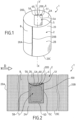
figure 1 illustre, selon une vue schématique en perspective, un article textile tubulaire selon l'invention, forme en l'occurrence un manchon élastique destiné à enserrer une partie du corps humain (coude, genou ou poignet par exemple), et qui est pourvu sur sa face interne d'un logement destiné à accueillir de façon amovible en son sein un élément fonctionnel indépendant, formé par exemple par une compresse thermique du type sachet rempli d'un gel eutectique. - la
figure 2 illustre, selon une vue de face, une bande textile conçue pour former, par assemblage mutuel de ses extrémités latérales, l'article tubulaire de lafigure 1 . - la
figure 3 illustre, selon une vue de dos, la bande de lafigure 2 . - la
figure 4 illustre, selon une vue schématique en perspective de dessus, un détail de réalisation de l'article textile tubulaire de lafigure 1 . - la
figure 5 illustre schématiquement et de façon agrandie une portion du premier tricot formant le premier panneau de l'article textile illustré aux figures précédentes. - L'invention concerne un article textile 1 destiné à entourer une partie d'un corps humain ou animal, à des fins thérapeutiques ou non-thérapeutiques. Avantageusement, l'article textile 1 est un article de contention, de compression, de maintien ou de stabilisation d'une partie d'un corps humain ou animal, laquelle est formée par exemple par une structure articulaire, musculaire ou osseuse, afin d'obtenir avantageusement un effet thérapeutique (ou préventif) par une action mécanique d'enserrement du segment corporel concerné, que ce soit par exemple en phase traumatique aiguë, au cours d'un processus de rééducation ou de convalescence (par exemple post-traumatique), ou pour prévenir un éventuel traumatisme ou une affection. L'article textile 1 selon l'invention forme ainsi avantageusement une orthèse, et en particulier une orthèse orthopédique comme par exemple une orthèse poignet/pouce, une orthèse poignet/main, un collier cervical, une ceinture lombaire, une coudière, une genouillère, etc. L'invention n'est cependant pas limitée à un article textile 1 thérapeutique visant à entourer une partie d'un corps humain ou animal en prévention ou en traitement d'un traumatisme, en particulier orthopédique. L'article textile 1 peut par exemple être conçu pour entourer une partie d'un corps humain ou animal en prévention ou en traitement de maux d'origine rhumatismale. L'article textile 1 consiste par conséquent avantageusement en un article textile, de préférence orthopédique, conçu pour entourer une partie d'un corps humain ou animal (faisant par exemple partie de l'appareil locomoteur) dans le cadre d'un traitement préventif ou curatif de maux d'origine traumatique ou rhumatismale et des douleurs associées.
- L'invention n'est toutefois pas limitée à un article thérapeutique. L'article textile 1 peut par exemple constituer un article textile 1 de confort, et se présenter par exemple sous la forme d'une « ceinture de chaleur» visant à maintenir au chaud la partie du corps humain ou animal concernée, sans but curatif ou préventif, ou encore par exemple sous la forme d'une « ceinture de grossesse » destiné à améliorer le confort de la femme enceinte en soutenant son abdomen.
- De manière générale, l'article textile 1 est donc un article textile thérapeutique (préventif ou curatif de maux d'origine traumatique ou organique) et/ou de confort, dont l'effet premier est basé essentiellement sur un enserrement élastique de la partie du corps humain ou animal à traiter.
- Selon une première variante, l'article textile 1 est conçu pour être porté par une personne humaine, afin d'entourer une partie du corps de la personne en question. Il est cependant parfaitement envisageable, selon une deuxième variante, que l'article textile 1 soit conçu pour être porté par un animal, par exemple un cheval, un chien, un chat, etc.
- L'invention concerne également un procédé de fabrication d'un tel article textile 1, de sorte que la description qui suit est applicable indifféremment à l'article 1 lui-même mais également au procédé de fabrication correspondant, et réciproquement.
- Comme illustré aux figures, l'article textile 1 selon l'invention comprend un premier panneau 2 destiné à entourer ladite partie du corps humain. A cette fin, le premier panneau 2 présente avantageusement une forme sensiblement tubulaire, de façon permanente ou temporaire. Comme illustré aux figures, le premier panneau 2 présente une face interne 2A destinée à se trouver en regard de ladite partie du corps humain à enserrer élastiquement ainsi qu'une face externe 2B opposée tournée vers l'extérieur. La face interne 2A est avantageusement destinée à venir directement au contact de la partie du corps humain à entourer. Dans le mode de réalisation illustré à la
figure 1 , le premier panneau 2 présente, de façon permanente, une forme tubulaire d'axe central X-X'. Dans ce cas, le premier panneau 2 forme un manchon destiné à être enfilé sur la partie du corps concernée (par exemple la cheville, le genou ou le coude...) par exemple pour assurer une contention, une compression un maintien ou une stabilisation de la partie du corps en question. Il est cependant tout à fait envisageable, sans pour autant que l'on sorte du cadre de l'invention, que le premier panneau 2 soit pourvu de moyens de verrouillage réversibles lui permettant d'évoluer entre une configuration ouverte, dans laquelle le premier panneau 2 se présente sous la forme d'une bande sensiblement plate, et une configuration fermée, dans laquelle le premier panneau 2 se présente sous la forme d'une gaine capable de ceindre la partie du corps concernée. Les moyens de verrouillage en question sont par exemple formés par un système de type velours/crochets (comme le système connu sous la marque déposée Velcro ®). - Ainsi, le premier panneau 2 se présente avantageusement sous la forme d'une bande 20, qui s'étend par exemple longitudinalement entre un premier bord latéral 20A et un deuxième bord latéral 20B (de préférence parallèles audit axe vertical central X-X'), et transversalement entre un premier bord longitudinal 20C et un deuxième bord longitudinal 20D. Ladite bande 20 est en l'espèce refermée sur elle-même, soit de façon permanente comme illustré à la
figure 1 (auquel cas les premier et deuxième bords longitudinaux 20A, 20B sont par exemple attachés l'un à l'autre sensiblement continûment sur toute leur hauteur, par exemple au moyen d'une couture, par collage ou tout autre moyen) soit de façon temporaire (auquel cas les premier et deuxième bords latéraux 20A, 20B sont pourvus de moyens de verrouillage complémentaires réversibles, par exemple du genre velours/crochets comme exposé précédemment), pour entourer ladite partie du corps humain. Dans l'exemple illustré aux figures, la bande 20 présente sensiblement une forme rectangulaire, dont les bords latéraux 20A, 20B et longitudinaux 20C, 20D sont rectilignes et parallèles deux à deux. Il est cependant parfaitement envisageable, sans pour autant que l'on sorte du cadre de l'invention, que les bords latéraux 20A, 20B et/ou longitudinaux 20C, 20D soit sensiblement courbes, de façon que l'article textile 1 présente une conformation parfaitement adaptée au segment corporel qu'il est destiné à enserrer. - Conformément à l'invention, le premier panneau 2 est constitué par un premier tricot, c'est-à-dire par une étoffe à mailles, de préférence à mailles cueillies, de sorte que le premier tricot formant le premier panneau 2 est avantageusement un tricot en trame, c'est-à-dire un tricot à mailles cueillies, dont les mailles sont disposées en rangs et en colonnes (cf.
figure 5 ). Ledit premier tricot formant le premier panneau 2 est composé de mailles elles-mêmes formées par au moins un premier fil 3, lequel peut être un fil naturel (coton par exemple) ou synthétique (polyamide ou polyester par exemple). Ledit premier tricot inclut en outre un tramage élastique pour permettre audit article 1 d'enserrer élastiquement ladite partie du corps humain. Le tramage élastique en question est formé d'au moins un fil élastique 4, qui est non tricoté (c'est à dire qui ne forme pas de mailles, contrairement audit premier fil 3), et qui s'étend de façon sensiblement rectiligne au sein du premier tricot, formant ainsi des « flottés » élastiques capturés au sein de la structure de mailles et destinés à impartir un comportement élastique spécifique et maîtrisé audit premier tricot. - Le procédé de fabrication selon l'invention comprend donc une étape (i) de fabrication d'un premier panneau 2, par tricotage d'au moins un premier fil 3 avec insertion d'un tramage élastique afin de permettre audit premier panneau 2 de pouvoir enserrer élastiquement la partie du corps humain à traiter. Comme exposé précédemment, l'étape (i) de fabrication du premier panneau 2 consiste avantageusement à tricoter en trame au moins le premier fil 3, ladite étape (i) étant avantageusement effectuée au moyen d'une tricoteuse industrielle, par exemple une tricoteuse industrielle rectiligne, de préférence à deux fontures au moins, capable de tricoter des bandes à plat.
- Les trames élastiques formant ledit tramage élastique inséré au sein dudit premier tricot sont par exemple formées à partir d'un ou plusieurs fils 4 en élasthanne ou en élastodiène, éventuellement guipés (par exemple avec un guipage coton). De préférence, les trames élastiques insérées dans le premier tricot, pour former ledit tramage élastique, sont formés par un seul et même fil élastique 4 continu déposé selon un trajet en méandres, par étages successifs reliés par des virages en lacets, la longueur des trames élastiques en question étant dans ce cas conjuguée à celle des rangs de mailles. Par exemple, comme illustré à la
figure 5 , chaque rang de mailles du premier tricot est associé à une trame élastique de longueur sensiblement identique à celle dudit rang. Le tramage élastique mis en oeuvre dans le premier tricot permet ainsi au premier panneau 2 d'étreindre élastiquement la partie du corps humain concernée, afin par exemple d'exercer un effort de compression élastique centripète sur cette dernière, de préférence à des fins thérapeutiques, par exemple pour assister ou stabiliser une structure articulaire ou musculaire. - Conformément à l'invention, l'article textile 1 comprend également un deuxième panneau 5 qui est superposé localement audit premier panneau 2, de sorte que l'article textile 1 est localement formé de deux couches, savoir une première couche formée par le premier panneau 2 et une deuxième couche, disposée sur et contre ladite première couche et formée par le deuxième panneau 5, lequel est en l'espèce de taille inférieure à celle du premier panneau 2, en particulier selon la direction longitudinale parallèle aux bords longitudinaux 20B, 20C. Conformément à l'invention, ledit deuxième panneau 5 est attaché au premier panneau 2 pour former avec ce dernier un logement 6. Les premier et deuxième panneaux 2, 5 sont donc liés mutuellement pour délimiter ensemble un volume d'accueil, formé par l'espace interstitiel entre le premier panneau 2 et le deuxième panneau 5, destiné à accueillir un élément fonctionnel indépendant 100. Comme illustré aux figures, le logement 6 est muni d'une ouverture d'accès 60 afin d'accueillir de façon amovible en son sein ledit élément fonctionnel indépendant 100, lequel forme un insert apte à être inséré, par ladite ouverture d'accès 60, dans le logement 6 ou être extrait hors dudit logement 6 par ladite ouverture 60. Le deuxième panneau 5 forme donc avec le premier panneau 2 un logement en forme d'étui, comme par exemple un fourreau, pourvu d'une ouverture d'accès 60 permettant à un utilisateur d'introduire ou de retirer à volonté, au sein ou hors dudit étui, l'élément fonctionnel 100, dont la taille et la forme sont avantageusement conjuguées à celles du logement 6.
- L'élément fonctionnel indépendant 100 peut être de toute nature adaptée à la fonction recherchée. De préférence, l'élément fonctionnel indépendant 100 peut constituer une compresse thermique, formée par exemple par un sachet rempli d'un gel eutectique afin de former un « pack gel chaud/froid ». Une telle compresse thermique peut être à usage unique (jetable) ou réutilisable. Dans ce dernier cas, ladite compresse thermique est avantageusement conçue pour être « rechargée » thermiquement par passage dans un four à micro-ondes (lorsque l'on souhaite apporter de la chaleur à la partie du corps enserrée par l'article textile 1) ou dans un congélateur (ou un réfrigérateur) lorsque l'on souhaite refroidir la partie du corps humain concernée. Ainsi, une fois installée dans le logement 6, la compresse thérapeutique peut transférer des calories ou des frigories à la partie du corps gainée par l'article textile 1. L'invention n'est bien entendu absolument pas limitée à la mise en oeuvre d'une compresse thermique en tant qu'élément fonctionnel indépendant 100, et il est par exemple tout à fait envisageable que ledit élément fonctionnel indépendant 100 soit formé par un dispositif de diffusion d'une substance active, comme par exemple une substance médicamenteuse topique telle qu'une substance antalgique. Il est également envisageable, selon un mode de réalisation alternatif, que l'élément fonctionnel indépendant 100 soit formé par un dispositif de compression à volume variable, comprenant par exemple une vessie destinée à être gonflée (par de l'air ou un liquide) afin d'imposer localement une surpression réglable, par exemple pour comprimer une veine ou une artère. L'invention concerne d'ailleurs en tant que tel un système comprenant d'une part ledit article textile 1 selon l'invention et d'autre part ledit élément fonctionnel indépendant 100 destiné à être accueilli de façon amovible au sein du logement 6 dudit article textile 1, ledit élément fonctionnel 100 faisant partie du groupe suivant :
- compresse thermique (à usage unique ou réutilisable),
- dispositif de diffusion d'une substance active, comme par exemple une substance antalgique (à usage unique ou réutilisable),
- dispositif de compression à volume variable.
- Conformément à l'invention, le deuxième panneau 5 est constitué par un deuxième tricot, qui est de préférence également, tout comme le premier tricot, un tricot à mailles cueillies, c'est-à-dire un tricot « en trame ». Conformément à une caractéristique importante de l'invention, ledit deuxième tricot formant le deuxième panneau 5 est composé de mailles formées par le premier fil 3, de sorte que le premier fil 3 est utilisé à la fois pour réaliser des mailles du premier tricot formant le premier panneau 2 et des mailles du deuxième tricot formant le deuxième panneau 5 superposé localement au premier panneau 2. Ainsi, le procédé de fabrication selon l'invention comprend une étape (ii) de fabrication, par tricotage dudit premier fil 3, du deuxième panneau 5 de sorte que ce dernier est superposé localement audit premier panneau 2 et est attaché à ce dernier pour former avec lui le logement 6 muni de l'ouverture d'accès 60 afin d'accueillir de façon amovible en son sein l'élément fonctionnel indépendant 100. Contrairement à l'enseignement de l'art antérieur, le deuxième panneau 5 n'est donc pas dans un premier temps rapporté contre le premier panneau 2 puis dans un deuxième temps fixé à ce dernier au moyen d'une couture, mais vient directement de matière avec le premier panneau 2, en étant fabriqué de concert avec ce dernier puisque le premier et le deuxième tricot sont réalisés par tricotage d'au moins fil commun, savoir le premier fil 3. Grâce à cette caractéristique technique, le deuxième panneau 5 est solidement attaché au premier panneau 2 sans pour autant que la fixation du deuxième panneau 5 au premier panneau 2 n'engendre le moindre inconfort puisque le deuxième panneau 5 s'étend directement dans la continuité de mailles du premier panneau 2. Un autre avantage réside dans le fait que le premier panneau 2 et le deuxième panneau 5 peuvent être réalisés dans le cadre d'une seule et même opération de tricotage. En particulier, les étapes (i) et (ii) de fabrication desdits premier et deuxième panneaux 2, 5 peuvent avantageusement être mises en oeuvre au cours d'une seule et même opération de tricotage, ce qui permet de fabriquer rapidement et à moindre coût l'article textile 1, qui présente en outre des propriétés de confort et de robustesse améliorées. Ainsi, dans le procédé de fabrication conformément à l'invention, les étapes (i), (ii) de fabrication desdits premier et deuxième panneaux 2, 5 sont effectuées, au moins en partie, simultanément, par exemple au moyen d'une seule et même tricoteuse industrielle rectiligne, comportant au moins deux fontures, et par exemple quatre fontures. Le procédé selon l'invention met ainsi avantageusement en oeuvre une unique étape de tricotage au cours de laquelle le deuxième panneau 5 est tricoté en même temps qu'une partie du premier panneau 2, selon de préférence un procédé de tricotage à plat. Ainsi, à l'issue desdites étapes de fabrication (i), (ii) desdits premier et deuxième panneaux 2, 5, ledit premier panneau 2 se présente avantageusement sous la forme d'une bande 20 (cf.
figure 2 ) plate sur laquelle est superposé localement ledit deuxième panneau 5, ledit procédé comportant avantageusement une étape de mise en forme de ladite bande 20 dans laquelle cette dernière est refermée et assemblée sur elle-même, par liaison mutuelle des bords latéraux 20A, 20B, pour conférer audit article 1 une forme tubulaire comme illustré à lafigure 1 . Dans le cas où l'article 1 est conçu pour présenter seulement temporairement une forme tubulaire, le procédé comporte par exemple, en lieu et place de l'étape de mise en forme susvisée, une étape consistant à pourvoir la bande 20 de moyens de fermeture complémentaires vers ses extrémités, lesdits moyens de fermeture complémentaires se présentant par exemple sous la forme d'un système velours/crochets avec des boucles disposées vers le premier bord latéral 20A et des crochets disposés vers le deuxième bord latéral 20B, ou inversement, afin de permettre à un utilisateur de refermer en boucle la bande 20 autour du segment corporel souhaité, et ce de façon réversible. - Selon l'invention, le deuxième panneau 5 comprend un bord libre 5A qui s'étend longitudinalement entre deux extrémités 50, 51 attachées audit premier panneau 2, ledit bord libre 5A délimitant, avec le premier panneau 2, ladite ouverture d'accès 60, qui présente donc en l'espèce une forme sensiblement allongée. Cela signifie que le bord délimitant l'ouverture d'accès 60 est formé d'une part par le bord libre 5A du deuxième panneau 5 et d'autre part par la portion 200 du premier panneau 2 située sensiblement au droit dudit bord libre 5A. Dans le mode de réalisation avantageux illustré aux figures, l'étape (ii) de fabrication dudit deuxième panneau 5 est mise en oeuvre de façon que ledit deuxième panneau 5 est attaché selon sensiblement tout son pourtour audit premier panneau 2, à l'exception d'une portion localisée dudit pourtour qui forme ledit bord libre 5A délimitant, avec le premier panneau 2, l'ouverture d'accès 60. Dans le mode de réalisation illustré aux figures, le premier panneau 2 présente globalement une forme rectangulaire avec un premier côté transversal 5B et un deuxième côté transversal 5C, lesquels sont par exemple sensiblement parallèles à l'axe central X-X', et un premier côté longitudinal, qui forme en l'espèce le bord libre 5A évoqué précédemment, ainsi qu'un deuxième côté longitudinal 5D qui lui est sensiblement parallèle. Dans ce cas, le pourtour du deuxième panneau 5 est formé par le premier côté transversal 5B, le deuxième côté transversal 5C, le premier côté longitudinal 5A et le deuxième côté longitudinal 5D. Dans le mode de réalisation illustré aux figures, chacun desdits premier côté longitudinal 5D, premier côté transversal 5B et deuxième côté transversal 5C est attaché, sur sensiblement toute sa longueur, au premier panneau 2, tandis que le reste du premier panneau 2 est libre et délimite ainsi un espace interstitiel entre le premier panneau 1 et le deuxième panneau 5 qui forme le logement 6. L'ouverture d'accès 60 est quant à elle définie par le premier bord longitudinal 5A qui est attaché au premier panneau 2 uniquement en ses extrémités 50, 51, contrairement aux autres côtés 5B, 5C, 5D qui sont attachés continûment au premier panneau 2. Ainsi, dans ce mode de réalisation préférentiel, le deuxième panneau 5 présente globalement une forme rectangulaire avec les quatre côtés 5A, 5B, 5C, 5D opposés deux à deux, le deuxième panneau 5 étant avantageusement attaché continûment audit premier panneau 2 le long d'au moins trois desdits côtés 5B, 5C, 5D, le dernier côté formant ledit bord libre 5A susvisé. Un tel mode de réalisation permet de réaliser aisément, par tricotage simultané du premier panneau 2 et du deuxième panneau 5, à la fois le logement 6 et son ouverture d'accès 60, laquelle s'ouvre dès lors sur la face du premier panneau 2 contre laquelle est disposée le deuxième panneau 5. Dans le mode de réalisation illustré aux figures, le deuxième panneau 5 est disposé sur la face interne 2A, contre cette dernière, l'ouverture d'accès 60 étant dans ce cas elle aussi disposée sur la face interne 2A. Une telle conception permet de positionner l'élément fonctionnel indépendant 100 au plus près de la partie du corps humain à traiter, tout en englobant ledit élément fonctionnel indépendant au moyen du premier panneau 2, ce qui permet par exemple d'éviter, ou en tous les cas de limiter, une éventuelle déperdition thermique vers l'extérieur, lorsque l'élément fonctionnel indépendant 100 est par exemple formé par une compresse thermique. Il est cependant parfaitement envisageable, sans pour autant que l'on sorte du cadre de l'invention, que le deuxième panneau 5 soit disposé sur la face externe 2B, et que l'ouverture d'accès 60 soit dans ce cas elle aussi disposée sur la face externe 2B, ce qui permet de faciliter l'accès au logement 6 lorsque l'article textile 1 est porté par un utilisateur. Une telle configuration est cependant moins favorable en ce qui concerne le maintien de l'élément fonctionnel indépendant 100 dans le logement 6, et en ce qui concerne également les éventuelles déperditions thermiques. Ainsi, dans le mode de réalisation avantageux illustré aux figures, l'ouverture d'accès 60 est entièrement disposée du même côté que le deuxième panneau 5, ce qui évite tout enlèvement de matière à travers le premier panneau 2 pour réaliser l'ouverture d'accès 60, un tel enlèvement de matière pouvant être préjudiciable à la fonction de contention/compression/maintien élastique assuré avantageusement par le premier panneau 2. L'invention n'est cependant pas limitée à la variante préférentielle illustrée aux figures, selon laquelle l'ouverture 60 est située du même côté du premier panneau 2 que le logement 6. Il est par exemple tout à fait envisageable, sans pour autant que l'on sorte du cadre de l'invention, que le deuxième panneau 5 soit attaché selon sensiblement tout son pourtour au premier panneau 2, sans exception, de sorte que tous les côtés 5A, 5B, 5C, 5D sont reliés sensiblement continûment audit premier panneau 2, l'ouverture d'accès 60 étant dans ce cas ménagé à travers l'épaisseur premier panneau 2, entre les faces internes 2A et externe 2B. Comme illustré aux figures, le bord libre 5A s'étend de préférence sensiblement parallèlement à la direction de tricotage D du premier tricot (et du deuxième tricot), de sorte que l'ouverture d'accès 60 s'étend en l'espèce longitudinalement selon ladite direction de tricotage D, parallèlement aux rangs de mailles formant les premier et deuxième tricots.
- De préférence, le deuxième panneau 5 est positionné à distance des premier et deuxième bords longitudinaux 20C, 20D de la bande 20, de sorte que le logement 6 est totalement englobé par le premier panneau 2, qui contribue ainsi au parfait maintien de l'élément fonctionnel indépendant 100 en place au sein du logement 6, grâce à l'action d'encerclement élastique du logement 6 exercée par le premier panneau 2. Dans ce mode de réalisation préférentiel, l'ouverture 60 ne s'ouvre donc pas au niveau de l'un desdits premier ou deuxième bords longitudinaux 20C, 20D, ce qui permet également de limiter la déperdition thermique (lorsque l'élément fonctionnel indépendant 100 est une compresse thermique) par l'ouverture d'accès 60 (ou de contenir la substance active émise par le dispositif de diffusion que peut constituer alternativement l'élément fonctionnel indépendant 100).
- Grâce au fait que le premier panneau 2 et le deuxième panneau 5 sont tous deux formés respectivement par un premier et un deuxième tricot, qui de surcroît incluent chacun des mailles formées par le même premier fil 3, les propriétés d'extensibilité élastique de l'article textile 1 peuvent être sensiblement uniformes, en dépit de la présence localisée, sur l'une des faces (en l'espèce la face interne 2A) du premier panneau 2, du deuxième panneau 5. Afin de préserver ce caractère uniforme, le deuxième panneau 5 est avantageusement sensiblement dépourvu de tramage élastique, contrairement au premier panneau 2, afin d'éviter que l'article textile 1 ne présente localement un double tramage qui pourrait induire une modification locale de l'extensibilité élastique de l'article textile 1 et donc une éventuelle irrégularité spatiale des propriétés de compression élastique de l'article textile 1.
- Cela signifie que ladite étape (ii) de fabrication dudit deuxième panneau 5 n'inclut avantageusement pas d'opération d'insertion d'un tramage élastique au sein dudit deuxième panneau 5. Ceci n'exclut pas toutefois la présence éventuelle de fils élastiques, par exemple intégrés par vanisage, dans le deuxième panneau 5, pour conférer une certaine souplesse à ce dernier. Il est également éventuellement envisageable, dans un mode de réalisation non revendiqué, que le deuxième panneau 5 puisse inclure également, comme le premier panneau 2, un tramage élastique, afin par exemple de bénéficier localement, au niveau du logement 6, d'un comportement élastique différent du fait de la superposition du tramage élastique du premier panneau 2 et du tramage élastique du deuxième panneau 5.
- Selon l'invention, il est revendiqué que le bord libre 5A formant le bord de l'ouverture d'accès 60 soit contraint élastiquement, par exemple au moyen d'un ou plusieurs fils élastiques insérés au niveau et le long dudit bord libre 5A. Cette mesure technique vise en particulier à conférer audit bord libre 5A une faculté d'extensibilité élastique évitant au bord libre 5A de bâiller ou de flotter de façon relâchée, ce qui pourrait favoriser un échappement intempestif de l'élément fonctionnel indépendance 100 hors du logement 6 et/ou occasionner la formation de plis, source d'inconfort. Comme illustré aux figures, le fil élastique 4 formant le tramage élastique du premier panneau 2 est également associé au bord libre 5A pour conférer à ce dernier des propriétés d'élasticité longitudinale. Ainsi, dans ce mode de réalisation selon l'invention, le fil élastique 4 est à la fois utilisé pour former les trames élastiques du premier panneau 2, afin de permettre à ce dernier d'assurer de façon adéquate une fonction de compression ou de contention élastique, et pour conférer au bord libre 5A délimitant l'ouverture d'accès 60 une extensibilité élastique permettant d'éviter de recourir à des moyens particuliers de fermeture de l'ouverture d'accès 60 pour maintenir l'élément fonctionnel indépendant 100 au sein du logement 6. Grâce à cette caractéristique, selon laquelle le fil élastique 4 du tramage élastique du premier panneau 2 est utilisé pour contraindre élastiquement le bord libre 5A, tout en étant par ailleurs avantageusement absent du reste du deuxième panneau 5 pour les raisons déjà exposées dans ce qui précède, la construction de l'article 1 est extrêmement simple, fiable et robuste, et ne nécessite en particulier pas d'introduire des fils supplémentaires pour travailler le bord libre 5. Cette opération d'association du fil élastique 4 au bord libre 5A peut en outre être effectuée dans le cadre de l'opération de tricotage conjointe des premier et deuxième panneaux 2, 5. Le procédé selon l'invention comprend donc avantageusement une étape d'association du fil élastique 4 au bord libre 5A pour conférer à ce dernier des propriétés d'élasticité longitudinale, ladite étape d'association susvisée étant avantageusement mise en oeuvre au moyen de la même tricoteuse industrielle rectiligne avantageusement utilisée pour fabriquer les premier et deuxième panneaux 2, 5.
- Avantageusement, ledit premier tricot formant le premier panneau 2 est plus épais que le deuxième tricot 5 formant le deuxième panneau 5. Cette caractéristique technique, lorsqu'elle est par exemple combinée à la caractéristique selon laquelle le logement 6 est disposé sur la face interne 2A, permet en particulier de faciliter d'éventuels transferts thermiques, à travers le deuxième panneau 5, entre l'élément fonctionnel indépendant 100 et la partie du corps humain contre laquelle le deuxième panneau 5 vient en contact lorsque le premier panneau 2 entoure la partie du corps humain en question. La mise en oeuvre d'un premier tricot d'épaisseur plus importante pour former le premier panneau 2 permet en outre de limiter la déperdition thermique vers l'extérieur. Dans le même but, le premier tricot 1 est avantageusement moins ajouré que le deuxième tricot, afin de faciliter les échanges thermiques et/ou la diffusion de substance active à travers le deuxième panneau 5.
- Ces différences d'épaisseur et de « degré de porosité » des premier et deuxième tricots peuvent être obtenues en jouant sur le liage et/ou sur la nature du ou des fil(s) tricoté(s) pour former les premier et deuxième tricots. Avantageusement, le premier tricot formant le premier panneau 2 est majoritairement réalisé par tricotage dudit premier fil 3 selon au moins un premier liage, par exemple un liage de type tricot trame à base côte (par exemple piqué toutes aiguilles trois chutes tramé). Comme cela sera décrit plus en détails dans ce qui suit, le premier tricot peut être réalisé par tricotage d'un ou plusieurs fils selon différents liages, de sorte que le premier tricot présente dans ce cas différentes structures de maille. Avantageusement, le deuxième tricot formant le deuxième panneau 5 est quant à lui majoritairement, et de préférence entièrement, réalisé par tricotage dudit premier fil 3 selon au moins un deuxième liage différent dudit premier liage mis en oeuvre pour former le premier tricot. Par exemple, le deuxième tricot est réalisé par tricotage dudit premier fil 3 en mailles Jersey (par exemple en mailles jersey déjaugées), afin d'obtenir un deuxième panneau 5 plus fin et plus ajouré que le premier panneau 2. Ledit deuxième liage est avantageusement choisi pour conférer au deuxième panneau 5 une extensibilité suffisante pour que la présence du deuxième panneau 5 sur la face interne du premier panneau 2 n'entrave pas l'extensibilité élastique de ce dernier, de façon à conserver ainsi des propriétés de compression élastique optimale.
- Comme illustré aux figures, le logement 6 constitue une poche formée par un panneau avant et un panneau arrière 7 mutuellement attachés en périphérie, ledit panneau avant étant formé par ledit deuxième panneau 5, tandis que le panneau arrière 7 est formé par une partie dudit premier panneau 2. Le panneau arrière 7 présente avantageusement, comme illustré aux figures, une forme et des dimensions sensiblement conjuguées à celles du panneau avant formé par le deuxième panneau 5. En l'espèce, le panneau arrière 7 présente ainsi une forme sensiblement rectangulaire et est lié le long de trois de ses bords au panneau avant, le long des bords 5B, 5C, 5D de ce dernier. Le premier panneau 2 est ainsi formé par ledit panneau arrière 7, ainsi que par un panneau principal 8 qui entoure au moins en partie ledit panneau arrière 7. Ainsi, dans l'exemple illustré aux figures, le panneau arrière 7 est entouré latéralement par le panneau principal 8, c'est-à-dire que le panneau principal 8 présente en l'espèce sensiblement une forme de bande rectangulaire avec un évidement rectangulaire rempli par le panneau arrière 7 (voir en particulier la
figure 3 ). Les mailles du premier tricot qui constituent ledit panneau principal 8 sont formées par ledit premier fil 3 ainsi que par un deuxième fil 9, tandis que les mailles du premier tricot qui constituent ledit panneau arrière 7 sont formées par ledit deuxième fil 9. Cela signifie que l'étape de fabrication (i) dudit premier panneau 2 comprend: - une opération de fabrication dudit panneau principal 8 par tricotage du premier fil 3 et dudit deuxième fil 9,
- et une opération de fabrication dudit panneau arrière 7 par tricotage dudit deuxième fil 9.
- Selon l'invention, et comme illustré aux figures, le panneau principal 8 est obtenu par tricotage à la fois du premier fil 3 et du deuxième fil 9 de façon à former des rangs de mailles alternativement constitués du premier fil 3 et du deuxième fil 9 et des colonnes de mailles dont les mailles sont alternativement constituées du premier fil 3 et du deuxième fil 9, par exemple dans la proportion de une maille sur deux comme illustré à la
figure 5 . Selon ce même exemple de réalisation, le panneau arrière 7 est obtenu par tricotage du deuxième fil 9 uniquement, tandis que le deuxième panneau 5 est lui obtenu par tricotage du premier fil 3 uniquement. Ainsi, dans le mode de réalisation préférentiel illustré aux figures, les mailles formant le panneau arrière 7 sont exclusivement constituées par le deuxième fil 9, tandis que les mailles constituant le deuxième panneau 5, qui est superposé au panneau arrière 7, sont exclusivement formées par le premier fil 3. - Cela signifie que lors de la fabrication de l'article textile 1 conforme aux figures, les premier et deuxième fils 3, 9 sont tout d'abord tricotés ensemble, avec insertion du tramage élastique, pour former la partie du premier panneau 2 correspondant au panneau principal 8, puis que chaque fil 3, 9 est ensuite tricoté séparément, et de préférence sensiblement simultanément, pour former au cours d'une même opération de tricotage respectivement le panneau arrière 7 (pour deuxième fil 9) et le deuxième panneau 5 (pour le premier fil 3). Le tramage élastique évoqué précédemment est quant à lui uniquement inséré dans la structure de mailles du panneau arrière 7 et associé au bord libre 5A comme revendiqué. Une fois le tricotage des panneau arrière 7 et deuxième panneau 5 terminés, les deux fils 3, 9 sont à nouveau tricotés ensemble selon par exemple le liage illustré à la
figure 5 , pour former le reste du panneau principal 8, au sein duquel est inséré le tramage élastique. Ainsi, dans le mode de réalisation illustré aux figures, les rangs de mailles du deuxième panneau 5 s'étendent respectivement dans la continuité de chacun des rangs de mailles du panneau principal 8, à la différence près qu'ils sont tous exclusivement formés par le premier fils 3. - Les colonnes de mailles formant le deuxième panneau 5 s'étendent quant à elles dans la continuité des colonnes de mailles du panneau principal 8, à la différence près qu'elles sont uniquement formées, dans l'exemple illustré aux figures, par le premier fil 3.
- En outre, afin de favoriser les échanges et transferts, en particulier thermiques, à travers le deuxième panneau 5, chaque colonne du panneau principal 8 s'étendant au droit du deuxième côté longitudinal 5D ne se prolonge pas systématiquement par une colonne de mailles du deuxième panneau 5, afin d'obtenir un deuxième tricot plus aéré. Par exemple, deux mailles sur trois du rang de mailles formant le deuxième côté longitudinal 5D forme la base d'une colonne de mailles du deuxième tricot formant le deuxième panneau 5.
- De préférence, lesdits premier et deuxième fils 3, 9 sont sensiblement identiques, et sont par exemple des fils de polyamide. Il est cependant tout à fait envisageable que les premier et deuxième fils 3, 9 soit différents, sans pour autant que l'on sorte du cadre de l'invention. Il est par exemple envisageable de mettre en oeuvre un premier fil 3 plus fin que le deuxième fil 9.
- En définitive, l'invention permet d'obtenir très simplement un article textile 1 de forme sensiblement tubulaire obtenu à partir d'un panneau 2 de compression élastique entièrement tricoté, avec une poche intégrée sans couture audit panneau 2, ce qui permet une efficacité (notamment en matière de transfert thermique), un confort et une esthétique particulièrement améliorés.
- L'invention trouve son application industrielle dans la conception, la fabrication et l'utilisation d'articles textiles.
Claims (10)
- - Article textile (1) comprenant un premier panneau (2) destiné à entourer une partie d'un corps humain ou animal, ledit premier panneau (2) étant constitué par un premier tricot qui est composé de mailles et qui inclut un tramage élastique pour permettre audit article (1) d'enserrer élastiquement ladite partie du corps humain ou animal, ledit article textile (1) comprenant un deuxième panneau (5) superposé localement audit premier panneau (2) et attaché à ce dernier pour former avec ledit premier panneau (2) un logement (6) qui est muni d'une ouverture d'accès (60) afin d'accueillir de façon amovible en son sein un élément fonctionnel indépendant (100), ledit logement (6) constituant une poche formée par un panneau avant et un panneau arrière (7) mutuellement attachés en périphérie, ledit panneau avant étant formé par ledit deuxième panneau (5), tandis que ledit premier panneau (2) est formé par ledit panneau arrière (7) ainsi que par un panneau principal (8) qui entoure au moins en partie ledit panneau arrière (7), les mailles dudit premier tricot qui constituent ledit panneau principal (8) étant formées par un premier fil (3) ainsi que par un deuxième fil (9), tandis que les mailles du premier tricot qui constituent ledit panneau arrière (7) sont formées par ledit deuxième fil (9), ledit deuxième panneau (5) étant constitué par un deuxième tricot composé de mailles formées par ledit premier fil (3), ledit deuxième panneau (5) comprenant un bord libre (5A) qui s'étend longitudinalement entre deux extrémités (50, 51) attachées audit premier panneau (2), ledit bord libre (5A) délimitant, avec le premier panneau (2), ladite ouverture d'accès (60), l'article textile étant caractérisé en ce que ledit tramage élastique est formé d'au moins un fil élastique (4) qui est également associé audit bord libre (5A) pour conférer à ce dernier des propriétés d'élasticité longitudinale, ledit fil élastique (4) du tramage élastique du premier panneau (2) étant utilisé pour contraindre élastiquement le bord libre (5A), tout en étant par ailleurs absent du reste du deuxième panneau (5).
- - Article textile (1) selon la revendication précédente caractérisé en ce que ledit premier panneau (2) présente une face interne (2A) destinée à se trouver en regard de ladite partie du corps humain ainsi qu'une face externe (2B) opposée, ledit deuxième panneau (5) étant disposé sur ladite face interne (2A), ladite ouverture d'accès (60) étant disposée sur ladite face interne (2A).
- - Article textile (1) selon l'une des revendications précédentes caractérisé en ce que ledit deuxième panneau (5) est attaché selon sensiblement tout son pourtour audit premier panneau (2), à l'exception d'une portion localisée dudit pourtour qui forme ledit bord libre (5A) délimitant avec le premier panneau (2) ladite ouverture d'accès (60).
- - Article textile selon l'une des revendications précédentes caractérisé en ce que lesdits premier et deuxième fils (3, 9) sont sensiblement identiques, et sont par exemple des fils de polyamide.
- - Système comprenant d'une part un article textile (1) selon l'une des revendications précédentes et d'autre part un élément fonctionnel indépendant (100) destiné à être accueilli de façon amovible au sein du logement (6) dudit article textile (1), ledit élément fonctionnel (100) faisant partie du groupe suivant :- compresse thermique,- dispositif de diffusion d'une substance active, comme par exemple une substance antalgique,- dispositif de compression à volume variable.
- - Procédé de fabrication d'un article textile (1) comprenant une étape (i) de fabrication d'un premier panneau (2), par tricotage avec insertion d'un tramage élastique, ledit premier panneau (2) étant destiné à enserrer élastiquement une partie d'un corps humain ou animal, ledit procédé comprenant une étape (ii) de fabrication, par tricotage d'un premier fil (3), d'un deuxième panneau (5) superposé localement audit premier panneau (2) et attaché à ce dernier pour former avec ledit premier panneau un logement (6) qui est muni d'une ouverture d'accès (60) afin d'accueillir de façon amovible en son sein un élément fonctionnel indépendant, ledit logement (6) constituant une poche formée par un panneau avant et un panneau arrière (7) mutuellement attachés en périphérie, ledit panneau avant étant formé par ledit deuxième panneau (5), tandis que ledit premier panneau (2) est formé par ledit panneau arrière (7) ainsi que par un panneau principal (8) qui entoure au moins en partie ledit panneau arrière (7), ladite étape de fabrication (i) dudit premier panneau (2) comprenant:- une opération de fabrication dudit panneau principal (8) par tricotage dudit premier fil (3) et d'un deuxième fil (9),- et une opération de fabrication dudit panneau arrière (7) par tricotage dudit deuxième fil (9),ledit deuxième panneau (5) comprenant un bord libre (5A) qui s'étend longitudinalement entre deux extrémités (50, 51) attachées audit premier panneau (2), ledit bord libre (5A) délimitant, avec le premier panneau (2), ladite ouverture d'accès (60), ledit tramage élastique étant formé d'au moins un fil élastique (4), le procédé étant caractérisé en ce qu'il comprend une étape d'association dudit fil élastique (4) audit bord libre (5A) pour conférer à ce dernier des propriétés d'élasticité longitudinale, ledit fil élastique (4) du tramage élastique du premier panneau (2) étant utilisé pour contraindre élastiquement le bord libre (5A), tout en étant par ailleurs absent du reste du deuxième panneau (5).
- - Procédé selon la revendication précédente caractérisé en ce que lesdites étapes (i), (ii) de fabrication desdits premier et deuxième panneaux (2, 5) sont effectuées, au moins en partie, simultanément.
- - Procédé selon l'une des revendications 6 et 7 caractérisé en ce que ladite étape (ii) de fabrication dudit deuxième panneau (5) est mise en oeuvre de façon que ledit deuxième panneau (5) soit attaché selon sensiblement tout son pourtour audit premier panneau (2), à l'exception d'une portion localisée dudit pourtour qui forme ledit bord libre (5A).
- - Procédé selon l'une des revendications 6 à 8 caractérisé en ce qu'à l'issue desdites étapes de fabrication (i), (ii) desdits premier et deuxième panneaux (2, 5), ledit premier panneau (2) se présente sous la forme d'une bande (20) sur laquelle est superposée localement ledit deuxième panneau (5), ledit procédé comportant une étape de mise en forme de ladite bande (20) dans laquelle cette dernière est refermée et assemblée sur elle-même pour conférer audit article (1) une forme tubulaire.
- -Procédé selon l'une des revendications 6 à 9 caractérisé en ce que lesdites étapes (i), (ii) de fabrication desdits premier et deuxième panneaux (2, 5) sont effectuées au moyen d'une tricoteuse industrielle rectiligne.
Applications Claiming Priority (1)
| Application Number | Priority Date | Filing Date | Title |
|---|---|---|---|
| PCT/FR2015/051739 WO2016207494A1 (fr) | 2015-06-26 | 2015-06-26 | Article textile a poche, système et procédé de fabrication afférents |
Publications (3)
| Publication Number | Publication Date |
|---|---|
| EP3314047A1 EP3314047A1 (fr) | 2018-05-02 |
| EP3314047C0 EP3314047C0 (fr) | 2024-08-21 |
| EP3314047B1 true EP3314047B1 (fr) | 2024-08-21 |
Family
ID=53785671
Family Applications (1)
| Application Number | Title | Priority Date | Filing Date |
|---|---|---|---|
| EP15747837.1A Active EP3314047B1 (fr) | 2015-06-26 | 2015-06-26 | Article textile à poche, système et son procédé de fabrication |
Country Status (2)
| Country | Link |
|---|---|
| EP (1) | EP3314047B1 (fr) |
| WO (1) | WO2016207494A1 (fr) |
Families Citing this family (1)
| Publication number | Priority date | Publication date | Assignee | Title |
|---|---|---|---|---|
| DE202018106294U1 (de) | 2018-11-05 | 2020-02-06 | Julius Zorn Gmbh | Medizinisches Gestrickteil |
Family Cites Families (4)
| Publication number | Priority date | Publication date | Assignee | Title |
|---|---|---|---|---|
| US5814003A (en) * | 1996-09-04 | 1998-09-29 | Alba-Waldensian, Inc. | Pulsatile anti-embolism stocking |
| FR2781817B1 (fr) * | 1998-07-31 | 2000-09-15 | Marcoux Laffay Sa | Procede de tricotage d'une poche dans un tricot trame, et tricot trame a poche obtenu |
| IT1305843B1 (it) * | 1998-09-10 | 2001-05-16 | Franco Sciacca | Metodo o apparecchiatura per la produzione di articoli tridimensionalie o conformati di miglieria e calzetteria tubolare,preferibilmente |
| US20070106356A1 (en) * | 2005-11-08 | 2007-05-10 | Carstens Jerry E | Body conforming shirt-like holder and therapeutic article |
-
2015
- 2015-06-26 WO PCT/FR2015/051739 patent/WO2016207494A1/fr not_active Ceased
- 2015-06-26 EP EP15747837.1A patent/EP3314047B1/fr active Active
Also Published As
| Publication number | Publication date |
|---|---|
| EP3314047C0 (fr) | 2024-08-21 |
| EP3314047A1 (fr) | 2018-05-02 |
| WO2016207494A1 (fr) | 2016-12-29 |
Similar Documents
| Publication | Publication Date | Title |
|---|---|---|
| EP2536370B1 (fr) | Orthèse compressive tubulaire | |
| OA10935A (fr) | Orthèse compressive du type botte pour le traitement des pathologies circulatoires des membres inférieurs notamment pour la contention de la jambe à la suite d'un ulcère veineux | |
| FR2635969A1 (fr) | Dispositif orthopedique de maintien et son procede de fabrication | |
| EP3320793B2 (fr) | Sous-vetement masculin | |
| WO2006085001A2 (fr) | Orthese souple amovible pour atteinte du medio-pied | |
| EP3873595B1 (fr) | Dispositif pour le traitement de patients par phototherapie | |
| EP3314047A1 (fr) | Article textile a poche, système et procédé de fabrication afférents | |
| FR3004639A1 (fr) | Ceinture lombaire a bandes de rappel | |
| FR2799347A1 (fr) | Casquette a taille variable comportant des soufflets en tricot trame deux fontures | |
| FR2715832A1 (fr) | Pansement stérile absorbant jetable pour les extrémités des membres. | |
| FR2934471A1 (fr) | Complexe textile pour le refroidissement d'un corps humain | |
| EP3716930B1 (fr) | Dispositif corporel de compression avec fermeture à boucles et crochets | |
| CN204971824U (zh) | 一种膝关节冰敷袋 | |
| EP3165194B1 (fr) | Dispositif de soutien d'un membre d'un animal | |
| FR3039061A1 (fr) | Attelle pour traitement par cryotherapie compressive sur l'articulation du genou | |
| EP1013248A1 (fr) | Dispositif immobilisateur de l'épaule et du membre supérieur et épaulette utilisable dans ce dispositif | |
| JP3177338U (ja) | 上半身用保温具 | |
| WO2014162073A1 (fr) | Nouveau bandeau de compression | |
| FR3004922A1 (fr) | Dispositif anti-ronflement | |
| FR3069169A1 (fr) | Dispositif d'exercice et d'auto-reeducation de la main et du poignet | |
| FR2789572A1 (fr) | Vetement anatomique de nuit | |
| FR2755604A1 (fr) | Dispositif d'abaissement local de la temperature du corps et notamment des membres | |
| WO2022117939A1 (fr) | Dispositif pour prevenir et soulager les rachialgies | |
| FR2515028A1 (fr) | Justaucorps orthopedique souple pour la correction des scolioses | |
| CA2258119C (fr) | Orthese compressive de type botte pour le traitement des pathologies circulatoires des membres inferieurs, notamment pour la contention de la jambe a la suite d'un ulcere veineux |
Legal Events
| Date | Code | Title | Description |
|---|---|---|---|
| STAA | Information on the status of an ep patent application or granted ep patent |
Free format text: STATUS: THE INTERNATIONAL PUBLICATION HAS BEEN MADE |
|
| PUAI | Public reference made under article 153(3) epc to a published international application that has entered the european phase |
Free format text: ORIGINAL CODE: 0009012 |
|
| STAA | Information on the status of an ep patent application or granted ep patent |
Free format text: STATUS: REQUEST FOR EXAMINATION WAS MADE |
|
| 17P | Request for examination filed |
Effective date: 20180126 |
|
| AK | Designated contracting states |
Kind code of ref document: A1 Designated state(s): AL AT BE BG CH CY CZ DE DK EE ES FI FR GB GR HR HU IE IS IT LI LT LU LV MC MK MT NL NO PL PT RO RS SE SI SK SM TR |
|
| AX | Request for extension of the european patent |
Extension state: BA ME |
|
| RAP1 | Party data changed (applicant data changed or rights of an application transferred) |
Owner name: SIMP ORTHO SOLUTIONS |
|
| DAV | Request for validation of the european patent (deleted) | ||
| DAX | Request for extension of the european patent (deleted) | ||
| STAA | Information on the status of an ep patent application or granted ep patent |
Free format text: STATUS: EXAMINATION IS IN PROGRESS |
|
| 17Q | First examination report despatched |
Effective date: 20210528 |
|
| GRAP | Despatch of communication of intention to grant a patent |
Free format text: ORIGINAL CODE: EPIDOSNIGR1 |
|
| STAA | Information on the status of an ep patent application or granted ep patent |
Free format text: STATUS: GRANT OF PATENT IS INTENDED |
|
| INTG | Intention to grant announced |
Effective date: 20231222 |
|
| GRAJ | Information related to disapproval of communication of intention to grant by the applicant or resumption of examination proceedings by the epo deleted |
Free format text: ORIGINAL CODE: EPIDOSDIGR1 |
|
| STAA | Information on the status of an ep patent application or granted ep patent |
Free format text: STATUS: EXAMINATION IS IN PROGRESS |
|
| GRAP | Despatch of communication of intention to grant a patent |
Free format text: ORIGINAL CODE: EPIDOSNIGR1 |
|
| STAA | Information on the status of an ep patent application or granted ep patent |
Free format text: STATUS: GRANT OF PATENT IS INTENDED |
|
| INTC | Intention to grant announced (deleted) | ||
| INTG | Intention to grant announced |
Effective date: 20240510 |
|
| GRAS | Grant fee paid |
Free format text: ORIGINAL CODE: EPIDOSNIGR3 |
|
| GRAA | (expected) grant |
Free format text: ORIGINAL CODE: 0009210 |
|
| STAA | Information on the status of an ep patent application or granted ep patent |
Free format text: STATUS: THE PATENT HAS BEEN GRANTED |
|
| AK | Designated contracting states |
Kind code of ref document: B1 Designated state(s): AL AT BE BG CH CY CZ DE DK EE ES FI FR GB GR HR HU IE IS IT LI LT LU LV MC MK MT NL NO PL PT RO RS SE SI SK SM TR |
|
| REG | Reference to a national code |
Ref country code: GB Ref legal event code: FG4D Free format text: NOT ENGLISH |
|
| REG | Reference to a national code |
Ref country code: CH Ref legal event code: EP |
|
| REG | Reference to a national code |
Ref country code: DE Ref legal event code: R096 Ref document number: 602015089601 Country of ref document: DE |
|
| REG | Reference to a national code |
Ref country code: IE Ref legal event code: FG4D Free format text: LANGUAGE OF EP DOCUMENT: FRENCH |
|
| U01 | Request for unitary effect filed |
Effective date: 20240920 |
|
| U07 | Unitary effect registered |
Designated state(s): AT BE BG DE DK EE FI FR IT LT LU LV MT NL PT RO SE SI Effective date: 20241014 |
|
| PG25 | Lapsed in a contracting state [announced via postgrant information from national office to epo] |
Ref country code: NO Free format text: LAPSE BECAUSE OF FAILURE TO SUBMIT A TRANSLATION OF THE DESCRIPTION OR TO PAY THE FEE WITHIN THE PRESCRIBED TIME-LIMIT Effective date: 20241121 |
|
| PG25 | Lapsed in a contracting state [announced via postgrant information from national office to epo] |
Ref country code: GR Free format text: LAPSE BECAUSE OF FAILURE TO SUBMIT A TRANSLATION OF THE DESCRIPTION OR TO PAY THE FEE WITHIN THE PRESCRIBED TIME-LIMIT Effective date: 20241122 Ref country code: PL Free format text: LAPSE BECAUSE OF FAILURE TO SUBMIT A TRANSLATION OF THE DESCRIPTION OR TO PAY THE FEE WITHIN THE PRESCRIBED TIME-LIMIT Effective date: 20240821 |
|
| PG25 | Lapsed in a contracting state [announced via postgrant information from national office to epo] |
Ref country code: IS Free format text: LAPSE BECAUSE OF FAILURE TO SUBMIT A TRANSLATION OF THE DESCRIPTION OR TO PAY THE FEE WITHIN THE PRESCRIBED TIME-LIMIT Effective date: 20241221 |
|
| PG25 | Lapsed in a contracting state [announced via postgrant information from national office to epo] |
Ref country code: HR Free format text: LAPSE BECAUSE OF FAILURE TO SUBMIT A TRANSLATION OF THE DESCRIPTION OR TO PAY THE FEE WITHIN THE PRESCRIBED TIME-LIMIT Effective date: 20240821 |
|
| PG25 | Lapsed in a contracting state [announced via postgrant information from national office to epo] |
Ref country code: RS Free format text: LAPSE BECAUSE OF FAILURE TO SUBMIT A TRANSLATION OF THE DESCRIPTION OR TO PAY THE FEE WITHIN THE PRESCRIBED TIME-LIMIT Effective date: 20241121 Ref country code: ES Free format text: LAPSE BECAUSE OF FAILURE TO SUBMIT A TRANSLATION OF THE DESCRIPTION OR TO PAY THE FEE WITHIN THE PRESCRIBED TIME-LIMIT Effective date: 20240821 |
|
| PG25 | Lapsed in a contracting state [announced via postgrant information from national office to epo] |
Ref country code: RS Free format text: LAPSE BECAUSE OF FAILURE TO SUBMIT A TRANSLATION OF THE DESCRIPTION OR TO PAY THE FEE WITHIN THE PRESCRIBED TIME-LIMIT Effective date: 20241121 Ref country code: PL Free format text: LAPSE BECAUSE OF FAILURE TO SUBMIT A TRANSLATION OF THE DESCRIPTION OR TO PAY THE FEE WITHIN THE PRESCRIBED TIME-LIMIT Effective date: 20240821 Ref country code: NO Free format text: LAPSE BECAUSE OF FAILURE TO SUBMIT A TRANSLATION OF THE DESCRIPTION OR TO PAY THE FEE WITHIN THE PRESCRIBED TIME-LIMIT Effective date: 20241121 Ref country code: IS Free format text: LAPSE BECAUSE OF FAILURE TO SUBMIT A TRANSLATION OF THE DESCRIPTION OR TO PAY THE FEE WITHIN THE PRESCRIBED TIME-LIMIT Effective date: 20241221 Ref country code: HR Free format text: LAPSE BECAUSE OF FAILURE TO SUBMIT A TRANSLATION OF THE DESCRIPTION OR TO PAY THE FEE WITHIN THE PRESCRIBED TIME-LIMIT Effective date: 20240821 Ref country code: GR Free format text: LAPSE BECAUSE OF FAILURE TO SUBMIT A TRANSLATION OF THE DESCRIPTION OR TO PAY THE FEE WITHIN THE PRESCRIBED TIME-LIMIT Effective date: 20241122 Ref country code: ES Free format text: LAPSE BECAUSE OF FAILURE TO SUBMIT A TRANSLATION OF THE DESCRIPTION OR TO PAY THE FEE WITHIN THE PRESCRIBED TIME-LIMIT Effective date: 20240821 |
|
| PG25 | Lapsed in a contracting state [announced via postgrant information from national office to epo] |
Ref country code: SM Free format text: LAPSE BECAUSE OF FAILURE TO SUBMIT A TRANSLATION OF THE DESCRIPTION OR TO PAY THE FEE WITHIN THE PRESCRIBED TIME-LIMIT Effective date: 20240821 |
|
| PG25 | Lapsed in a contracting state [announced via postgrant information from national office to epo] |
Ref country code: CZ Free format text: LAPSE BECAUSE OF FAILURE TO SUBMIT A TRANSLATION OF THE DESCRIPTION OR TO PAY THE FEE WITHIN THE PRESCRIBED TIME-LIMIT Effective date: 20240821 |
|
| PG25 | Lapsed in a contracting state [announced via postgrant information from national office to epo] |
Ref country code: SK Free format text: LAPSE BECAUSE OF FAILURE TO SUBMIT A TRANSLATION OF THE DESCRIPTION OR TO PAY THE FEE WITHIN THE PRESCRIBED TIME-LIMIT Effective date: 20240821 |
|
| PLBE | No opposition filed within time limit |
Free format text: ORIGINAL CODE: 0009261 |
|
| STAA | Information on the status of an ep patent application or granted ep patent |
Free format text: STATUS: NO OPPOSITION FILED WITHIN TIME LIMIT |
|
| 26N | No opposition filed |
Effective date: 20250522 |
|
| U20 | Renewal fee for the european patent with unitary effect paid |
Year of fee payment: 11 Effective date: 20250625 |
|
| REG | Reference to a national code |
Ref country code: CH Ref legal event code: H13 Free format text: ST27 STATUS EVENT CODE: U-0-0-H10-H13 (AS PROVIDED BY THE NATIONAL OFFICE) Effective date: 20260127 |
|
| PG25 | Lapsed in a contracting state [announced via postgrant information from national office to epo] |
Ref country code: MC Free format text: LAPSE BECAUSE OF FAILURE TO SUBMIT A TRANSLATION OF THE DESCRIPTION OR TO PAY THE FEE WITHIN THE PRESCRIBED TIME-LIMIT Effective date: 20240821 |
|
| GBPC | Gb: european patent ceased through non-payment of renewal fee |
Effective date: 20250626 |
|
| PG25 | Lapsed in a contracting state [announced via postgrant information from national office to epo] |
Ref country code: GB Free format text: LAPSE BECAUSE OF NON-PAYMENT OF DUE FEES Effective date: 20250626 |
|
| PG25 | Lapsed in a contracting state [announced via postgrant information from national office to epo] |
Ref country code: IE Free format text: LAPSE BECAUSE OF NON-PAYMENT OF DUE FEES Effective date: 20250626 |
|
| PG25 | Lapsed in a contracting state [announced via postgrant information from national office to epo] |
Ref country code: CH Free format text: LAPSE BECAUSE OF NON-PAYMENT OF DUE FEES Effective date: 20250630 |