EP3314083B1 - Dispositif, système et procédé de modification d'écoulement - Google Patents
Dispositif, système et procédé de modification d'écoulement Download PDFInfo
- Publication number
- EP3314083B1 EP3314083B1 EP16813406.2A EP16813406A EP3314083B1 EP 3314083 B1 EP3314083 B1 EP 3314083B1 EP 16813406 A EP16813406 A EP 16813406A EP 3314083 B1 EP3314083 B1 EP 3314083B1
- Authority
- EP
- European Patent Office
- Prior art keywords
- flow modification
- body portions
- cylindrical element
- modification device
- raised
- Prior art date
- Legal status (The legal status is an assumption and is not a legal conclusion. Google has not performed a legal analysis and makes no representation as to the accuracy of the status listed.)
- Active
Links
Images




Classifications
-
- F—MECHANICAL ENGINEERING; LIGHTING; HEATING; WEAPONS; BLASTING
- F15—FLUID-PRESSURE ACTUATORS; HYDRAULICS OR PNEUMATICS IN GENERAL
- F15D—FLUID DYNAMICS, i.e. METHODS OR MEANS FOR INFLUENCING THE FLOW OF GASES OR LIQUIDS
- F15D1/00—Influencing flow of fluids
- F15D1/10—Influencing flow of fluids around bodies of solid material
- F15D1/12—Influencing flow of fluids around bodies of solid material by influencing the boundary layer
-
- F—MECHANICAL ENGINEERING; LIGHTING; HEATING; WEAPONS; BLASTING
- F16—ENGINEERING ELEMENTS AND UNITS; GENERAL MEASURES FOR PRODUCING AND MAINTAINING EFFECTIVE FUNCTIONING OF MACHINES OR INSTALLATIONS; THERMAL INSULATION IN GENERAL
- F16L—PIPES; JOINTS OR FITTINGS FOR PIPES; SUPPORTS FOR PIPES, CABLES OR PROTECTIVE TUBING; MEANS FOR THERMAL INSULATION IN GENERAL
- F16L1/00—Laying or reclaiming pipes; Repairing or joining pipes on or under water
- F16L1/12—Laying or reclaiming pipes on or under water
- F16L1/123—Devices for the protection of pipes under water
-
- E—FIXED CONSTRUCTIONS
- E21—EARTH OR ROCK DRILLING; MINING
- E21B—EARTH OR ROCK DRILLING; OBTAINING OIL, GAS, WATER, SOLUBLE OR MELTABLE MATERIALS OR A SLURRY OF MINERALS FROM WELLS
- E21B17/00—Drilling rods or pipes; Flexible drill strings; Kellies; Drill collars; Sucker rods; Cables; Casings; Tubings
- E21B17/01—Risers
- E21B17/012—Risers with buoyancy elements
-
- F—MECHANICAL ENGINEERING; LIGHTING; HEATING; WEAPONS; BLASTING
- F15—FLUID-PRESSURE ACTUATORS; HYDRAULICS OR PNEUMATICS IN GENERAL
- F15D—FLUID DYNAMICS, i.e. METHODS OR MEANS FOR INFLUENCING THE FLOW OF GASES OR LIQUIDS
- F15D1/00—Influencing flow of fluids
- F15D1/10—Influencing flow of fluids around bodies of solid material
-
- B—PERFORMING OPERATIONS; TRANSPORTING
- B63—SHIPS OR OTHER WATERBORNE VESSELS; RELATED EQUIPMENT
- B63B—SHIPS OR OTHER WATERBORNE VESSELS; EQUIPMENT FOR SHIPPING
- B63B21/00—Tying-up; Shifting, towing, or pushing equipment; Anchoring
- B63B21/20—Adaptations of chains, ropes, hawsers, or the like, or of parts thereof
- B63B2021/203—Mooring cables or ropes, hawsers, or the like; Adaptations thereof
-
- B—PERFORMING OPERATIONS; TRANSPORTING
- B63—SHIPS OR OTHER WATERBORNE VESSELS; RELATED EQUIPMENT
- B63B—SHIPS OR OTHER WATERBORNE VESSELS; EQUIPMENT FOR SHIPPING
- B63B21/00—Tying-up; Shifting, towing, or pushing equipment; Anchoring
- B63B21/50—Anchoring arrangements or methods for special vessels, e.g. for floating drilling platforms or dredgers
- B63B21/502—Anchoring arrangements or methods for special vessels, e.g. for floating drilling platforms or dredgers by means of tension legs
- B63B2021/504—Anchoring arrangements or methods for special vessels, e.g. for floating drilling platforms or dredgers by means of tension legs comprising suppressors for vortex induced vibrations
-
- B—PERFORMING OPERATIONS; TRANSPORTING
- B63—SHIPS OR OTHER WATERBORNE VESSELS; RELATED EQUIPMENT
- B63B—SHIPS OR OTHER WATERBORNE VESSELS; EQUIPMENT FOR SHIPPING
- B63B21/00—Tying-up; Shifting, towing, or pushing equipment; Anchoring
- B63B21/20—Adaptations of chains, ropes, hawsers, or the like, or of parts thereof
-
- B—PERFORMING OPERATIONS; TRANSPORTING
- B63—SHIPS OR OTHER WATERBORNE VESSELS; RELATED EQUIPMENT
- B63B—SHIPS OR OTHER WATERBORNE VESSELS; EQUIPMENT FOR SHIPPING
- B63B21/00—Tying-up; Shifting, towing, or pushing equipment; Anchoring
- B63B21/50—Anchoring arrangements or methods for special vessels, e.g. for floating drilling platforms or dredgers
- B63B21/502—Anchoring arrangements or methods for special vessels, e.g. for floating drilling platforms or dredgers by means of tension legs
-
- B—PERFORMING OPERATIONS; TRANSPORTING
- B63—SHIPS OR OTHER WATERBORNE VESSELS; RELATED EQUIPMENT
- B63B—SHIPS OR OTHER WATERBORNE VESSELS; EQUIPMENT FOR SHIPPING
- B63B21/00—Tying-up; Shifting, towing, or pushing equipment; Anchoring
- B63B21/56—Towing or pushing equipment
- B63B21/66—Equipment specially adapted for towing underwater objects or vessels, e.g. fairings for tow-cables
Definitions
- the present invention relates to devices, systems and methods for reducing vortex-induced vibration (VIV) and/or overall drag on a generally cylindrical or tubular element immersed in a fluid medium.
- the invention is particularly suited to reducing VIV and drag on marine structures such as risers, umbilicals, cables, and pipelines.
- Cylindrical structures such as marine risers, umbilicals, cables, and pipelines will generally be subject to vortex-induced vibration excitation when immersed in a flowing fluid medium, or when moving relative to the fluid medium. This dynamic excitation can result in an amplified drag force and a decreased operating life due to fatigue.
- cylindrical structures are used in production and drilling risers, pipelines near the seabed, seawater intakes, discharge lines, and many other similar structures. Generally, these cylindrical structures will be subject to VIV, which can be more problematic with greater flow/current speed and longer cylinder lengths.
- Flow modification devices have been developed to reduce the level or severity of VIV on cylindrical structures. These flow modification devices aim to prevent coherent vortices from shedding about the cylindrical structure.
- U.S. patent no. 8,443,896 describes a flow modification device, in the form of a plurality of helical strakes, connectable to a marine riser. Helical strakes may reduce the severity of VIV to very small levels, but are generally large and not practical to handle. For example, drilling risers involve deployment, retrieval, and stacking operations which are not easily achieved with large helical strake devices.
- U.S. patent no. 7,513,209 and U.S. patent no. 6,223,672 describe rigid fairing devices connectable to marine risers.
- Rigid fairings aim to suppress VIV by streamlining and delaying separation of the flow about the cylindrical structure.
- Rigid fairings are typically unidirectional devices and generally involve clamping the fairing to the cylindrical structure. The clamping process can be time consuming, which is disadvantageous in light of expensive production and operating schedules, for example, when undertaking drilling operations.
- Vortex shedding about cylindrical structures is generally described in Flow-Induced Vibrations: An Engineering Guide (2005) by Naudacher, E. and Rockwell, D. from Dover Publications. Further flow modification devices and/or methods are disclosed in the following patent publications: FR 2367148 A1 , WO 2002/095278 A1 , CN 104453730 A and WO 2009/035481 .
- the present invention provides a flow modification device according to the appended independent claim 1.
- Preferable embodiments of the present invention are provided by the appended dependent claims 2-7.
- a flow modification device connectable to a generally cylindrical element adapted for immersion in a fluid medium, the device comprising:
- the plurality of raised body portions are preferably not continuous along the entire length of the elongate body.
- the second plurality of raised body portions may be off-set about the longitudinal axis with respect to the first plurality of raised body portions such that the second plurality of raised body portions are not aligned with the first plurality of raised body portions.
- the second plurality of raised body portions are longitudinally off-set or rotated about the longitudinal axis with respect to the first plurality of raised body portions by a rotation angle, which rotation angle is preferably approximately half the angle between adjacent raised body portions of the first plurality of raised body portions (as measured from centrelines of adjacent raised body portions).
- the flow modification device includes one or more additional pluralities of raised body portions disposed along one or more additional respective lengths of the elongate body, and each of the one or more additional pluralities of raised body portions is longitudinally off-set or rotated about the longitudinal axis with respect to an adjacent plurality of raised body portions disposed along an adjacent length of the elongate body.
- the elongate body includes 2, 3, 4 or more lengths of raised body portions in which each length of raised body portion is longitudinally offset or rotated about the longitudinal axis with respect to an adjacent length of raised body portion.
- the plurality of raised body portions are generally curved or rounded ridges and preferably have a radii between 2% and 38% of an outer diameter of the body.
- the elongate body preferably includes 4 or more or 5 or more curved or rounded ridges disposed equidistant about the elongate body. More preferably, the elongate body includes 12 or less or 9 or less curved or rounded ridges disposed equidistant about the elongate body. Still more preferably, the elongate body includes an odd number of curved or rounded ridges, such as 5, 7, or 9 curved or rounded ridges disposed equidistant about the elongate body.
- the curved or rounded ridges may be disposed in a manner about the elongate body such that adjacent curved or rounded ridges are not equidistant from one another.
- adjacent curved or rounded ridges may have a differing height.
- the terms "generally curved or rounded ridges”, “curved raised body portions”, “curved strakes” or any similar variations define any suitably curved or curve-like raised body portion geometry, or any substantially continuous geometry having no definite corners.
- the raised body portions may be generally parabolic in shape.
- the curved or rounded ridges define respective grooved body portions therebetween.
- the respective grooved body portions are generally concave and have a generally curved shape.
- the generally curved grooved body portions preferably have radii between 0.75% and 78% of the diameter of the body.
- the grooved body portions may be generally convex (or outwardly directed) and may have a generally curved shape (or the grooved body portions may adopt the primary or base shape of the generally circular elongate body, or be concentric thereto).
- the plurality of raised body portions are generally trapezoidal ridges.
- the trapezoidal ridges may have either chamfered or radiused corners and preferably have widths between 3% and 7% of the outer diameter of the body, but more preferably about 3% of the outer diameter.
- the elongate body preferably includes between 3 and 16 trapezoidal ridges (or strakes) disposed equidistant about the elongate body.
- the elongate body may include a relatively low number of trapezoidal ridges disposed equidistant about the elongate body (for example 3, 4, or 5 trapezoidal ridges).
- the elongate body may include a relatively high number of trapezoidal ridges disposed equidistant about the elongate body (for example 12, 14, or 16 trapezoidal ridges).
- the trapezoidal ridges may be disposed in a manner about the elongate body such that adjacent trapezoidal ridges are not equidistant from one another.
- adjacent trapezoidal ridges may have a differing height.
- the generally trapezoidal ridges may optionally define respective grooved body portions therebetween.
- the respective grooved body portions have an outwardly directed generally curved (or convex) shape (or the grooved body portions may adopt the primary or base shape of the generally circular elongate body, or be concentric thereto).
- the generally curved grooved body portions preferably have radii between 0.75% and 78% of the diameter of the body.
- the respective grooved body portions may be generally concave and have a generally curved shape.
- the flow modification device may comprise at least two releasably connectable complementary parts, such as a first part and a second part.
- the flow modification device is divided about its longitudinal axis to define the first and second parts.
- the first part may be a first half of the flow modification device
- the second part may be a second half of the flow modification device.
- the first and second parts may be releasably connectable, for example by a clamping means, so as to releasably secure the flow modification device about the cylindrical element.
- the generally cylindrical element is a continuous rubber or metal extrusion.
- the cylindrical element is a composite winding.
- the cylindrical element is a continuous reinforced concrete element.
- the cylindrical element may be a marine riser, cable, umbilical, tubular member, or other similar structural element.
- the flow modification device may be externally fitted, for example by sliding or clamping, to any type of generally cylindrical or tubular structure immersed in a fluid.
- Such structures include, by way of example only, chimneys, cables, drilling risers and their buoyancy elements, moorings, risers and umbilicals on fixed platforms, riser and umbilical distributed buoyancy elements (the buoys themselves) such as lazy wave risers, seawater intakes, semisubmersible legs and bracing members, spars, and subsea systems including rigid seabed spools.
- the present flow modification device is particularly suited for connection to buoyancy elements.
- Buoyancy elements typically comprise syntactic foam with rigid outer shells, and are designed to withstand large hydrostatic crushing pressures at great sea depths. Their displacement provides buoyancy to the structural element that they are connected to.
- the present flow modification device may be fabricated such that it has the abovementioned features of typical buoyancy elements.
- the flow modification device reduces VIV and drag on the cylindrical element when the flow modification device (or a plurality of flow modification devices) are arranged about and releasably secured to the cylindrical element.
- a flow modification system for the reduction of vortex-induced vibration and/or drag on a generally cylindrical element immersed in a fluid medium comprising:
- the means for releasably securing a flow modification device about the cylindrical element comprises an elongate strap.
- the elongate strap may be receivable about the elongate body of the flow modification device.
- the elongate strap may include recessed tensioners or internal bolted fasteners that act to tighten the elongate strap about the flow modification device (and therefore the cylindrical element).
- the plurality of raised body portions of a first flow modification device may be aligned with the immediately adjacent plurality of raised body portions of a second adjacent flow modification device.
- the raised body portions of the first flow modification device may not be aligned with the immediately adjacent plurality of raised body portions of the second adjacent flow modification device.
- the raised body portions of the first flow modification device may be longitudinally off-set or rotated about the longitudinal axis with respect to the immediately adjacent raised body portions of the second adjacent flow modification device by a rotation angle, which rotation angle is preferably half the angle between adjacent raised body portions of the first flow modification device (as measured from centrelines of adjacent raised body portions).
- each flow modification device of the plurality of flow modification devices arranged about the cylindrical element may be longitudinally off-set or rotated with respect to an adjacent flow modification device.
- groups of one or more flow modification devices may be longitudinally off-set or rotated with respect to an adjacent group of one or more flow modification devices.
- the flow modification device of these embodiments may include one or more additional adjacent pluralities of raised body portions that are longitudinally off-set or rotated with respect to one another in the manner described above.
- a method for reducing vortex-induced vibration and/or drag on a generally cylindrical element immersed in a fluid medium comprising the steps of:
- the means for releasably securing a flow modification device about the cylindrical element comprises an elongate strap.
- the elongate strap may be receivable about the elongate body of the flow modification device.
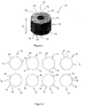
- a flow modification device 10 connectable to a generally cylindrical element (not shown) immersed in a fluid medium such as water or air.
- the generally cylindrical element may be a marine riser, cable, umbilical, or other similar tubular member.
- the flow modification device 10 provides vortex-induced vibration (VIV) suppression and drag reduction advantages due to the cross-sectional shape of the device 10.
- VIV vortex-induced vibration
- the cross-sectional shape of the device 10 alters the way in which vortices are formed as compared to typical substantially circular cross-sections, as described below in relation to Figure 9 .
- the flow modification device 10 is meant to be connected to or installed on an existing cylindrical element.
- the flow modification device 10 includes an elongate body 12 having a length L and a generally circular cross-section.
- the device 10 also includes a plurality of raised body portions (or strakes) in the form of generally curved or rounded ridges 14 disposed about and extending along the length L of the elongate body 12.
- the curved or rounded ridges 14 are arranged generally parallel to a longitudinal axis of the elongate body 12 and have a height between 2% and 10% of an outer diameter D of the body 12, but more preferably between 2% and 7.5% of the outer diameter D.
- the diameter D is the diameter of a circle drawn through the outermost edges of the raised body portions (or strakes). In other words, a circle intersecting the outermost edges of the raised body portions would have the diameter D.
- the flow modification device 10 also includes an aperture 16 extending through the length L of the elongate body 12.
- the aperture 16 is appropriately sized and dimensioned so as to receive the generally cylindrical element (not shown) such that the flow modification device 10 is arranged about the cylindrical element.
- the plurality of raised body portions or curved or rounded ridges 14 are adapted to reduce vortex-induced vibration and drag on the cylindrical element when the device 10 is connected to the cylindrical element, and when the connected device 10 and cylindrical element are immersed in the fluid medium and there is relative movement between the connected device and cylindrical element and the fluid medium.
- the plurality of curved or rounded ridges 14 define respective grooved body portions 18 therebetween.
- the grooved body portions 18 are generally concave and have a generally inverted or inwardly directed curved shape (as compared to the outwardly directed curved shape of the raised body portions or ridges 14).
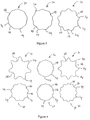
- the grooved body portions 18 may adopt the primary or base shape of the generally circular elongate body 12 (as is shown particularly in Figure 4 ).
- the flow modification device 10 includes four generally curved or rounded ridges 14 disposed equidistant about the elongate body (shown top-left). In alternative embodiments, the flow modification device 10 includes either five, six, seven, eight, nine, eleven, or twelve curved or rounded ridges 14 (shown top-left to bottom-right respectively). The number and relative size of the curved or rounded ridges 14 has an effect on the amplitude of vibration and the coefficient of drag of the cylindrical element, as is described below.
- the grooved body portions 18 disposed intermediate to adjacent curved or rounded ridges 14 preferably have radii between 0.75% and 78% of the diameter of the elongate body 12, as is described below.
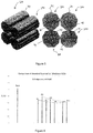
- Figure 3 shows further alternative embodiments of the flow modification device 10.
- the flow modification device 10 includes nine curved or rounded ridges 14 disposed equidistant about the elongate body.
- the height of the curved or rounded ridges 14 is 2% of the diameter of the body 12.
- the height of the curved or rounded ridges 14 is 3.8% or 7.1 % of the diameter (shown left to right respectively).
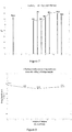
- Figure 4 shows further alternative embodiments of the flow modification device 10 in which the plurality of raised body portions (or strakes) 14 are generally trapezoidal ridges.
- the elongate body preferably includes between 3 and 16 trapezoidal ridges disposed equidistant about the elongate body.
- the flow modification device 10 includes seven generally trapezoidal ridges 14 disposed equidistant about the elongate body (shown top-left).
- the flow modification device 10 includes either eight, nine, or twelve trapezoidal ridges 14 (shown top-left to bottom-right respectively).
- the trapezoidal ridges have either chamfered or radiused corners and preferably have widths between 3% and 7% of the outer diameter of the body, but more preferably about 3% of the outer diameter.
- the generally trapezoidal ridges 14 define respective grooved body portions 18 therebetween.
- the respective grooved body portions 18 have an outwardly directed generally curved (or convex) shape (or, in other words, the grooved body portions adopt the primary or base shape of the generally circular elongate body).
- the generally curved grooved body portions 18 preferably have radii between 0.75% and 78% of the diameter of the body.
- the plurality of raised body portions may not be continuous along the entire length of the elongate body.
- the second plurality of raised body portions may be off-set about the longitudinal axis with respect to the first plurality of raised body portions such that the second plurality of raised body portions are not aligned with the first plurality of raised body portions.
- the second plurality of raised body portions are longitudinally off-set or rotated about the longitudinal axis with respect to the first plurality of raised body portions by a rotation angle, which rotation angle is preferably approximately half the angle between adjacent raised body portions of the first plurality of raised body portions (as measured from centrelines of adjacent raised body portions).
- the flow modification device may also include one or more additional pluralities of raised body portions disposed along one or more additional respective lengths of the elongate body, and each of the one or more additional pluralities of raised body portions may be longitudinally off-set or rotated about the longitudinal axis with respect to an adjacent plurality of raised body portions disposed along an adjacent length of the elongate body.
- a plurality of cylindrical elements 100 incorporating some of the above described features of the flow modification device 10 are stackable, for example, on a deck of a drilling rig.
- the generally curved or rounded ridges 14 of a lowermost cylindrical element are substantially seated or received within the grooved body portions 18 of an uppermost cylindrical element, thereby allowing the lowermost and uppermost cylindrical elements to be stacked.
- the generally curved or rounded ridges 14 act a male "locking" feature to the complementary female grooved body portions 18.
- VIV suppression devices such as those incorporating helical strakes.
- VIV devices incorporating helical strakes generally suffer damage when stacked due to point loading on their sharp raised edges.
- the flow modification device 10 may be manufactured as a buoyancy element.
- an outer shell comprising fibreglass or polyethylene is initially constructed.
- the outer shell may be moulded such that it has the above described cross-sectional features.
- Closed-cell foam, such as syntactic foam may then be injected or set within the outer shell.
- the syntactic foam may consist of macro-spheres and/or micro-spheres and/or resin depending upon the application and water depth being designed for. The required material will be apparent to those skilled in the relevant art.
- the flow modification device 10 may be entirely machined out of closed-cell or syntactic foam. In this embodiment, a separate outer shell is not required to be constructed.
- the amplitude of vibration of various cylindrical elements incorporating generally curved or rounded ridges according to an embodiment of the invention is plotted against a bare cylinder (i.e. a cylinder having a standard circular cross-section) in Figure 6 .
- the values referred to as R5 to R12 on the x-axis refer to the number of curved or rounded ridges 14 disposed about the elongate cylindrical body 12.
- R5 refers to a cylindrical element incorporating five curved or rounded ridges 14
- R12 refers to a cylindrical element incorporating twelve curved or rounded ridges 14.
- the amplitude of vibration is represented on the y-axis by the non-dimensional quantity A/D and is the mean of the maximum amplitude of vibration for a series of steady state tests.
- A/D the non-dimensional quantity
- a cylindrical element incorporating nine curved or rounded ridges 14 exhibited the lowest amplitude of vibration compared to the other tested cylindrical elements.
- the flow modification device 10 or cylindrical element 100 exhibited a lower amplitude of vibration as compared to the bare cylinder.
- Figure 7 details the static drag performance of the various cylindrical elements 10.
- the static drag is represented by the drag coefficient C D , which is plotted on the y-axis.
- the various geometries i.e. R5 to R12
- the drag coefficient C D is a non-dimensional quantity that is used to quantify the drag or resistance of an object in a fluid medium.
- a lower drag coefficient indicates that an object will have lower total drag as compared to an object having a higher drag coefficient.
- embodiments of the flow modification device 10 or cylindrical element 100 incorporating five, seven, or eight curved or rounded ridges 14 realise the greatest static drag benefits.
- Figure 8 details the total performance drag under freely vibrating conditions of the R9 cylinder, i.e. the cylindrical element incorporating nine curved or rounded ridges 14, having a height of 2.0%, 3.8%, or 7.1% of the diameter (referred to as 'OD' in Figure 8 ) of the body 12.
- a preferred embodiment of the flow modification device 10 having nine curved or rounded ridges 14 and a ridge height of approximately 3.8% yields the lowest total dynamic drag coefficient of the results plotted in Figure 8 . From this, it could be inferred that a height of less than 4%, or 3.8% or less, is preferred. The lower preferred height is 2% or more.
- FIG 9 details the downstream vorticity wake formation performance of the R9 cylinder as compared to the bare cylinder.
- Downstream vorticity wake formation is a way of assessing how vortices are shed from a cylinder.
- the flow modification device 10 advantageously sheds an elongated vortex per half cycle rather than a circular vortex per half cycle, which results in a reduced peak loading. By reducing the peak loading, the R9 cylinder is subject to less vibration and drag (and therefore less fatigue) as compared to the bare cylinder.
- Figure 10 details the static drag performance of various cylindrical elements 10 incorporating trapezoidal ridges or strakes according to an embodiment not covered by the invention.
- the static drag is represented by the drag coefficient C D , which is plotted on the y-axis.
- the number of raised body portions or strakes of various trapezoidal geometries are plotted on the x-axis.
- embodiments of the flow modification device 10 or cylindrical element 100 incorporating 3, 5, 12, or higher trapezoidal raised body portions or ridges realise greater static drag benefits over those with raised body portions in the mid-range (6 through 10 trapezoidal raised body portions).
- the amplitude of vibration of various cylindrical elements incorporating trapezoidal ridges or strakes according to the invention is plotted in Figure 11 .
- the amplitude of vibration is represented on the y-axis by the non-dimensional quantity A/D and is the mean of the maximum amplitude of vibration for a series of steady state tests.
- A/D the non-dimensional quantity
- a cylindrical element incorporating fewer trapezoidal ridges 14 exhibited the lowest amplitude of vibration compared to the other tested cylindrical elements.
- the flow modification device 10 or cylindrical element 100 exhibited a lower amplitude of vibration as compared to a bare cylinder.
- Figure 12 details the static drag performance of various cylindrical elements 10 incorporating trapezoidal ridges against the width of the trapezoidal ridges.
- a preferred embodiment of the flow modification device 10 has a width around 3% of the outside diameter, which yields the lowest static drag coefficient of the results plotted in Figure 12 .
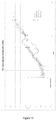
- Figures 13 and 14 compare the vibration characteristics of a freely vibrating R8 cylindrical element 100 having a first plurality of continuous (or aligned) curved or rounded ridges disposed along its length ( Fig. 13 ) to a similar freely vibrating R8 cylindrical element having at least a first plurality of curved or rounded ridges that are longitudinally off-set from a second adjacent plurality of curved or rounded ridges ( Fig. 14 ).
- the R8 cylindrical element of Fig. 14 includes four alternating or longitudinally off-set sections of curved or rounded ridges, with the curved or rounded ridges of a first section or length being aligned with the grooved body portions of a second adjacent section or length.
- the R8 cylindrical element of Figures 13 and 14 has a length to diameter ratio of approximately 17, and the data shown was generated at a high Reynolds number.
- the dimensionless amplitude of vibration (A*) of the R8 cylindrical element with continuous or aligned ridges peaks at approximately 0.7 ( Fig. 13 )
- the amplitude of vibration (A*) of the R8 cylindrical element with alternating or longitudinally off-set sections of ridges peaks at a much lower value of approximately 0.26 ( Fig. 14 ).
- a cylindrical element 100 incorporating sets or groups of longitudinally off-set or non-aligned raised body portions results in a lower dynamic vibration response (and therefore lower drag and dynamic fatigue), and is therefore preferred to a cylindrical element incorporating raised body portions that are continuously aligned along its length.
- the data of Figures 13 and 14 indicates that it is preferable that the plurality of raised body portions of a first flow modification device are not aligned with the plurality of raised body portions of a second adjacent flow modification device.
- the second flow modification device is longitudinally off-set or rotated about the longitudinal axis with respect to the first flow modification device by a rotation angle, which rotation angle may be approximately half the angle between adjacent raised body portions of the first flow modification device (as measured from centrelines of adjacent raised body portions).
- the flow modification device 10 or cylindrical element 100 of the present disclosure can be utilised or incorporated into a variety of structures as detailed below.
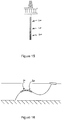
- Figure 15 shows an application in which the present flow modification device 10 or cylindrical element 100 may be utilised.
- the flow modification device 10 or cylindrical element 100 is shown as an integral part of an external surface of buoyancy units which are typically required on deep water drilling risers to aid in suspending the weight of the riser.
- FIG 16 shows a further application in which the present flow modification device 10 or cylindrical element 100 may be utilised.
- the flow modification device 10 or cylindrical element 100 is shown as an integral part of an external surface of discrete buoyancy units which are utilised to create a compliant wave shape in the depicted steel lazy wave riser or flexible lazy wave riser.
- VIV suppression advantages may result thereby offering enhanced fatigue performance of the underlying structural riser when compared to standard circular cross-section buoyancy units. Drag reduction advantages may also be realised when compared to standard circular cross-section buoyancy units.
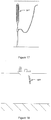
- FIG 17 shows a further application in which the present flow modification device 10 or cylindrical element 100 may be utilised.
- the flow modification device 10 or cylindrical element 100 is shown as an integral part of an external surface of a single discrete large buoyancy unit which provides vertical uplift to an underlying subsea riser structure. Such large buoyancy units are typically subjected to vortex-induced motion effects which can lead to greater problematic drag forces and greater fatigue on the connections and underlying structure.
- the present flow modification device or cylindrical element is shown on the external surface of the buoyancy unit with the longitudinal raised body portions or ridges 14 shown vertically. Alternatively, if the buoyancy unit has a primary axis configured horizontally, then the ridges 14 may be positioned horizontally (i.e., generally parallel to the seabed).
- FIG 18 shows a further application in which the present flow modification device 10 or cylindrical element 100 may be utilised.
- the flow modification device 10 or cylindrical element 100 is shown as an integral part of an external surface of a flexible free-hanging hose.
- VIV suppression and drag advantages may result thereby offering enhanced fatigue performance and drag reduction of the underlying metallic components in the structural hose or riser when compared to standard circular cross-section hoses.
- Figure 19 shows a further application in which the present flow modification device 10 or cylindrical element 100 may be utilised.
- the flow modification device 10 or cylindrical element 100 is shown as an integral part of an external surface of a chimney stack in air.
- the present flow modification device 10 offers manufacturing advantages over existing technologies, such as helical strakes, as the flow modification device 10 can be formed into the process of manufacturing the base chimney. Manufacturing of the base chimney may be done via a rolled and welded process or via a continuous concrete pour, whereas helical strakes are required to be fitted after the manufacturing of the base chimney.
Landscapes
- Engineering & Computer Science (AREA)
- Mechanical Engineering (AREA)
- General Engineering & Computer Science (AREA)
- Fluid Mechanics (AREA)
- Physics & Mathematics (AREA)
- Geology (AREA)
- Mining & Mineral Resources (AREA)
- Life Sciences & Earth Sciences (AREA)
- Environmental & Geological Engineering (AREA)
- General Life Sciences & Earth Sciences (AREA)
- Geochemistry & Mineralogy (AREA)
- Physical Or Chemical Processes And Apparatus (AREA)
- Other Liquid Machine Or Engine Such As Wave Power Use (AREA)
Claims (7)
- Dispositif de modification d'écoulement (10) pouvant être connecté à un élément généralement cylindrique adapté pour une immersion dans un milieu fluide, le dispositif comprenant :un corps allongé (12) présentant une longueur et une section transversale généralement circulaire ;une pluralité de parties de corps surélevées (14) disposées autour du corps allongé (12) et s'étendant le long de la longueur de celui-ci, les parties de corps surélevées (14) étant agencées généralement parallèlement à un axe longitudinal du corps (12) et présentant une hauteur comprise entre 2 % et 10 % d'un diamètre (D) du corps, dans lequel le diamètre (D) du corps (12) correspond au diamètre d'un cercle recoupant les bords les plus extérieurs des parties de corps surélevées (14) ; etune ouverture (16) s'étendant à travers la longueur du corps allongé (12), l'ouverture (16) étant adaptée à recevoir l'élément généralement cylindrique de telle sorte que le dispositif de modification d'écoulement (10) soit agencé autour de l'élément cylindrique ;dans lequel la pluralité de parties de corps surélevées (14) sont des arêtes généralement incurvées ou arrondies qui définissent des parties de corps rainurées respectives (18) entre elles, pour fournir une succession de parties de corps surélevées et rainurées qui présentent une géométrie sensiblement continue ne comprenant pas de coins définis ; etdans lequel la pluralité de parties de corps surélevées (14) sont adaptées pour réduire les vibrations et/ou la traînée induites par vortex sur l'élément cylindrique lorsque le dispositif (10) est connecté à l'élément cylindrique et que le dispositif connecté ainsi que l'élément cylindrique sont immergés dans le milieu fluide et qu'il existe un déplacement relatif entre le dispositif connecté et l'élément cylindrique et le milieu fluide ;dans lequel la pluralité de parties de corps surélevées (14) comprend une première pluralité de parties de corps surélevées disposées le long d'une première longueur du corps allongé (12) et une seconde pluralité de parties de corps surélevées disposées le long d'une seconde longueur adjacente du corps allongé (12), et dans lequel la seconde pluralité de parties de corps surélevées sont décalées autour de l'axe longitudinal par rapport à la première pluralité de parties de corps surélevées de telle sorte que la seconde pluralité de parties de corps surélevées ne soit pas alignée avec la première pluralité de parties de corps surélevées.
- Dispositif de modification d'écoulement selon la revendication 1, dans lequel les arêtes généralement incurvées ou arrondies (14) ont une hauteur comprise entre 2 % et 7,5 % du diamètre du corps (12).
- Dispositif de modification d'écoulement selon la revendication 2, dans lequel le corps allongé (12) comprend entre 4 et 12 arêtes incurvées ou arrondies (14) disposées à équidistance autour du corps allongé (12).
- Dispositif de modification d'écoulement selon la revendication 3, dans lequel chacune des arêtes incurvées ou arrondies (14) a des rayons compris entre 2 % et 38 % du diamètre du corps (12).
- Dispositif de modification d'écoulement selon la revendication 1, dans lequel chacune des parties de corps rainurées respectives (18) est généralement concave et a une forme généralement incurvée.
- Dispositif de modification d'écoulement selon la revendication 5, dans lequel chacune des parties de corps rainurées respectives (18) a des rayons compris entre 0,75 % et 78 % du diamètre du corps.
- Système de modification d'écoulement pour la réduction des vibrations et/ou de la traînée induites par vortex sur un élément généralement cylindrique immergé dans un milieu fluide, le système comprenant :une pluralité de dispositifs de modification d'écoulement (10) selon l'une quelconque des revendications 1 à 6, dans lequel chaque dispositif de modification d'écoulement (10) est agencé autour et s'étend le long de l'élément cylindrique ; etdes moyens pour fixer de manière amovible chacun de la pluralité de dispositifs de modification d'écoulement (10) autour de l'élément cylindrique.
Applications Claiming Priority (3)
| Application Number | Priority Date | Filing Date | Title |
|---|---|---|---|
| AU2015902488A AU2015902488A0 (en) | 2015-06-26 | A flow modification device, system, and method | |
| AU2015903879A AU2015903879A0 (en) | 2015-09-23 | A flow modification device having trapezoidal strakes and a system and method for modifying flow | |
| PCT/AU2016/050550 WO2016205898A1 (fr) | 2015-06-26 | 2016-06-27 | Dispositif, système et procédé de modification d'écoulement |
Publications (3)
| Publication Number | Publication Date |
|---|---|
| EP3314083A1 EP3314083A1 (fr) | 2018-05-02 |
| EP3314083A4 EP3314083A4 (fr) | 2019-03-06 |
| EP3314083B1 true EP3314083B1 (fr) | 2020-12-09 |
Family
ID=57584362
Family Applications (1)
| Application Number | Title | Priority Date | Filing Date |
|---|---|---|---|
| EP16813406.2A Active EP3314083B1 (fr) | 2015-06-26 | 2016-06-27 | Dispositif, système et procédé de modification d'écoulement |
Country Status (5)
| Country | Link |
|---|---|
| US (1) | US10323665B2 (fr) |
| EP (1) | EP3314083B1 (fr) |
| AU (1) | AU2016282213B2 (fr) |
| BR (1) | BR112017027561B1 (fr) |
| WO (1) | WO2016205898A1 (fr) |
Families Citing this family (3)
| Publication number | Priority date | Publication date | Assignee | Title |
|---|---|---|---|---|
| WO2017165926A1 (fr) * | 2016-04-01 | 2017-10-05 | Amog Technologies Pty Ltd | Dispositif de modification de flux possédant des virures hélicoïdales et système et procédé de modification de flux |
| SG11202001522QA (en) * | 2017-10-20 | 2020-05-28 | Balmoral Comtec Ltd | A cylindrical element profiled to reduce vortex induced vibration (viv) and/or drag |
| WO2020219678A2 (fr) * | 2019-04-23 | 2020-10-29 | Georgia Tech Research Corporation | Systèmes et procédés pour un suppresseur de bruit de fluide |
Citations (3)
| Publication number | Priority date | Publication date | Assignee | Title |
|---|---|---|---|---|
| FR2395481A1 (fr) * | 1977-06-22 | 1979-01-19 | Comp Generale Electricite | Tube d'echange thermique |
| US20140182731A1 (en) * | 2011-12-26 | 2014-07-03 | Akita University | Drainpipe, method for preventing blockage of drainpipe and installation structure of drainpipe |
| CN103982710A (zh) * | 2013-02-08 | 2014-08-13 | 泰州双羊精密无缝钢管有限公司 | 梅花型内圆异型无缝钢管 |
Family Cites Families (23)
| Publication number | Priority date | Publication date | Assignee | Title |
|---|---|---|---|---|
| FR2367148A1 (fr) * | 1976-10-05 | 1978-05-05 | Doris Dev Richesse Sous Marine | Procede de neutralisation de phenomenes oscillatoires parasites sur des colonnes immergees dans des fluides en mouvement et dispositif pour la mise en oeuvre dudit procede |
| CA1136545A (fr) * | 1979-09-28 | 1982-11-30 | Fathom Oceanology Limited | Systeme de flottation pour colonnes montantes de fortes dimensions en milieu marin |
| DE3609541A1 (de) * | 1986-03-21 | 1987-09-24 | Deutsche Forsch Luft Raumfahrt | Verminderten stroemungswiderstand durch herabgesetzte wandschubspannung aufweisende oberflaeche eines turbolent ueberstroemten koerpers |
| US6223672B1 (en) | 1996-11-15 | 2001-05-01 | Shell Oil Company | Ultrashort fairings for suppressing vortex-induced-vibration |
| GB2378493B (en) * | 1998-03-07 | 2003-04-09 | Crp Group Ltd | Protection of underwater elongate members |
| US6223372B1 (en) | 1998-08-07 | 2001-05-01 | Launce R. Barber | Combination carabiner and tool device |
| US6896447B1 (en) | 2000-11-14 | 2005-05-24 | Weldon Taquino | Vortex induced vibration suppression device and method |
| US6948884B2 (en) * | 2001-03-14 | 2005-09-27 | Technip France | Vortex-induced vibration reduction device for fluid immersed cylinders |
| GB0112164D0 (en) * | 2001-05-18 | 2001-07-11 | Crp Group Ltd | Protection of underwater elongate members |
| GB0321404D0 (en) * | 2003-09-12 | 2003-10-15 | Crp Group Ltd | Vacuum formed cladding |
| WO2006073931A2 (fr) * | 2005-01-03 | 2006-07-13 | Seahorse Equipment Corporation | Suppression du mouvement dynamique d'une ligne a catenaire |
| US8888411B2 (en) * | 2005-01-03 | 2014-11-18 | Krzysztof Jan Wajnikonis | Catenary line dynamic motion suppression |
| US7337742B1 (en) | 2006-08-09 | 2008-03-04 | Viv Suppression, Inc. | Twin fin fairing |
| US8684040B2 (en) | 2007-05-25 | 2014-04-01 | The Regents Of The University Of Michigan | Reduction of vortex induced forces and motion through surface roughness control |
| US7934888B2 (en) * | 2008-01-18 | 2011-05-03 | Viv Suppression, Inc. | Marine anti-foulant system and methods for using same |
| US8579546B2 (en) * | 2008-01-18 | 2013-11-12 | VIV Supression, Inc. | Apparatus and method for inhibiting vortex-induced vibration |
| US8297883B2 (en) * | 2008-04-07 | 2012-10-30 | Viv Suppression, Inc. | Underwater device for ROV installable tools |
| US8443896B2 (en) | 2009-06-04 | 2013-05-21 | Diamond Offshore Drilling, Inc. | Riser floatation with anti-vibration strakes |
| NL2005866C2 (nl) * | 2010-12-16 | 2012-06-19 | Lankhorst Mouldings B V | Omhullingselement voor een pijpleiding, alsmede matrijs voor vervaardiging daarvan. |
| JP5999469B2 (ja) * | 2011-11-11 | 2016-09-28 | 国立大学法人京都工芸繊維大学 | 流体抵抗低減構造及びその構造を用いた顔面又は頭部装着具 |
| GB201205059D0 (en) * | 2012-03-22 | 2012-05-09 | Trelleborg Offshore U K Ltd | Cladding |
| US8944722B1 (en) * | 2012-10-10 | 2015-02-03 | VIV Solutions, LLC | Spring systems for vortex suppression devices |
| CN104453730A (zh) | 2014-11-10 | 2015-03-25 | 西南石油大学 | 一种减小隔水管柱所受洋流阻力的浮力块表面结构 |
-
2016
- 2016-06-27 WO PCT/AU2016/050550 patent/WO2016205898A1/fr not_active Ceased
- 2016-06-27 EP EP16813406.2A patent/EP3314083B1/fr active Active
- 2016-06-27 US US15/738,816 patent/US10323665B2/en active Active
- 2016-06-27 AU AU2016282213A patent/AU2016282213B2/en active Active
- 2016-06-27 BR BR112017027561-9A patent/BR112017027561B1/pt active IP Right Grant
Patent Citations (3)
| Publication number | Priority date | Publication date | Assignee | Title |
|---|---|---|---|---|
| FR2395481A1 (fr) * | 1977-06-22 | 1979-01-19 | Comp Generale Electricite | Tube d'echange thermique |
| US20140182731A1 (en) * | 2011-12-26 | 2014-07-03 | Akita University | Drainpipe, method for preventing blockage of drainpipe and installation structure of drainpipe |
| CN103982710A (zh) * | 2013-02-08 | 2014-08-13 | 泰州双羊精密无缝钢管有限公司 | 梅花型内圆异型无缝钢管 |
Also Published As
| Publication number | Publication date |
|---|---|
| AU2016282213A1 (en) | 2017-12-21 |
| BR112017027561B1 (pt) | 2023-01-31 |
| BR112017027561A2 (pt) | 2018-09-04 |
| EP3314083A4 (fr) | 2019-03-06 |
| WO2016205898A1 (fr) | 2016-12-29 |
| US20180180073A1 (en) | 2018-06-28 |
| US10323665B2 (en) | 2019-06-18 |
| EP3314083A1 (fr) | 2018-05-02 |
| AU2016282213B2 (en) | 2020-07-30 |
Similar Documents
| Publication | Publication Date | Title |
|---|---|---|
| US6948884B2 (en) | Vortex-induced vibration reduction device for fluid immersed cylinders | |
| EP2049805B1 (fr) | Carénage à deux ailettes | |
| US20100061809A1 (en) | Systems and methods for reducing drag and/or vortex induced vibration | |
| EP3004519B1 (fr) | Éléments de tuyau et procédés de fabrication | |
| US20070003372A1 (en) | Systems and methods for reducing drag and/or vortex induced vibration | |
| US8152414B2 (en) | Device and method for suppressing vortex-induced vibrations | |
| US20110200396A1 (en) | Systems and methods for reducing drag and/or vortex induced vibration | |
| EP3314082B1 (fr) | Élément cylindrique conçu pour réduire une vibration et/ou une résistance induites par un tourbillon | |
| EP3314083B1 (fr) | Dispositif, système et procédé de modification d'écoulement | |
| EP3393900B1 (fr) | Dispositif de modification de flux possédant des virures hélicoïdales et système et procédé de modification de flux | |
| AU2007323831B2 (en) | Systems and methods for reducing drag and/or vortex induced vibration | |
| BR112018069175B1 (pt) | Dispositivo e sistema de modificação de fluxo e método para reduzir a vibração | |
| WO2009046166A1 (fr) | Systèmes et procédés de réduction des vibrations induites par tourbillon et/ou traînée | |
| WO2009102711A1 (fr) | Systèmes et procédés pour réduire une vibration induite par la traînée et/ou par un vortex |
Legal Events
| Date | Code | Title | Description |
|---|---|---|---|
| STAA | Information on the status of an ep patent application or granted ep patent |
Free format text: STATUS: THE INTERNATIONAL PUBLICATION HAS BEEN MADE |
|
| PUAI | Public reference made under article 153(3) epc to a published international application that has entered the european phase |
Free format text: ORIGINAL CODE: 0009012 |
|
| STAA | Information on the status of an ep patent application or granted ep patent |
Free format text: STATUS: REQUEST FOR EXAMINATION WAS MADE |
|
| 17P | Request for examination filed |
Effective date: 20180110 |
|
| AK | Designated contracting states |
Kind code of ref document: A1 Designated state(s): AL AT BE BG CH CY CZ DE DK EE ES FI FR GB GR HR HU IE IS IT LI LT LU LV MC MK MT NL NO PL PT RO RS SE SI SK SM TR |
|
| AX | Request for extension of the european patent |
Extension state: BA ME |
|
| DAV | Request for validation of the european patent (deleted) | ||
| DAX | Request for extension of the european patent (deleted) | ||
| A4 | Supplementary search report drawn up and despatched |
Effective date: 20190205 |
|
| RIC1 | Information provided on ipc code assigned before grant |
Ipc: E21B 17/10 20060101AFI20190130BHEP Ipc: F16D 1/06 20060101ALI20190130BHEP Ipc: B63B 21/50 20060101ALI20190130BHEP Ipc: E21B 15/02 20060101ALI20190130BHEP Ipc: B63B 21/66 20060101ALI20190130BHEP Ipc: F16L 55/04 20060101ALI20190130BHEP Ipc: F15D 1/12 20060101ALI20190130BHEP |
|
| STAA | Information on the status of an ep patent application or granted ep patent |
Free format text: STATUS: EXAMINATION IS IN PROGRESS |
|
| 17Q | First examination report despatched |
Effective date: 20200205 |
|
| GRAP | Despatch of communication of intention to grant a patent |
Free format text: ORIGINAL CODE: EPIDOSNIGR1 |
|
| STAA | Information on the status of an ep patent application or granted ep patent |
Free format text: STATUS: GRANT OF PATENT IS INTENDED |
|
| INTG | Intention to grant announced |
Effective date: 20200624 |
|
| GRAS | Grant fee paid |
Free format text: ORIGINAL CODE: EPIDOSNIGR3 |
|
| GRAA | (expected) grant |
Free format text: ORIGINAL CODE: 0009210 |
|
| STAA | Information on the status of an ep patent application or granted ep patent |
Free format text: STATUS: THE PATENT HAS BEEN GRANTED |
|
| AK | Designated contracting states |
Kind code of ref document: B1 Designated state(s): AL AT BE BG CH CY CZ DE DK EE ES FI FR GB GR HR HU IE IS IT LI LT LU LV MC MK MT NL NO PL PT RO RS SE SI SK SM TR |
|
| REG | Reference to a national code |
Ref country code: GB Ref legal event code: FG4D |
|
| REG | Reference to a national code |
Ref country code: AT Ref legal event code: REF Ref document number: 1343637 Country of ref document: AT Kind code of ref document: T Effective date: 20201215 Ref country code: CH Ref legal event code: EP |
|
| REG | Reference to a national code |
Ref country code: DE Ref legal event code: R096 Ref document number: 602016049547 Country of ref document: DE |
|
| REG | Reference to a national code |
Ref country code: IE Ref legal event code: FG4D |
|
| PG25 | Lapsed in a contracting state [announced via postgrant information from national office to epo] |
Ref country code: FI Free format text: LAPSE BECAUSE OF FAILURE TO SUBMIT A TRANSLATION OF THE DESCRIPTION OR TO PAY THE FEE WITHIN THE PRESCRIBED TIME-LIMIT Effective date: 20201209 Ref country code: GR Free format text: LAPSE BECAUSE OF FAILURE TO SUBMIT A TRANSLATION OF THE DESCRIPTION OR TO PAY THE FEE WITHIN THE PRESCRIBED TIME-LIMIT Effective date: 20210310 Ref country code: RS Free format text: LAPSE BECAUSE OF FAILURE TO SUBMIT A TRANSLATION OF THE DESCRIPTION OR TO PAY THE FEE WITHIN THE PRESCRIBED TIME-LIMIT Effective date: 20201209 Ref country code: NO Free format text: LAPSE BECAUSE OF FAILURE TO SUBMIT A TRANSLATION OF THE DESCRIPTION OR TO PAY THE FEE WITHIN THE PRESCRIBED TIME-LIMIT Effective date: 20210309 |
|
| REG | Reference to a national code |
Ref country code: AT Ref legal event code: MK05 Ref document number: 1343637 Country of ref document: AT Kind code of ref document: T Effective date: 20201209 |
|
| PG25 | Lapsed in a contracting state [announced via postgrant information from national office to epo] |
Ref country code: LV Free format text: LAPSE BECAUSE OF FAILURE TO SUBMIT A TRANSLATION OF THE DESCRIPTION OR TO PAY THE FEE WITHIN THE PRESCRIBED TIME-LIMIT Effective date: 20201209 Ref country code: BG Free format text: LAPSE BECAUSE OF FAILURE TO SUBMIT A TRANSLATION OF THE DESCRIPTION OR TO PAY THE FEE WITHIN THE PRESCRIBED TIME-LIMIT Effective date: 20210309 Ref country code: SE Free format text: LAPSE BECAUSE OF FAILURE TO SUBMIT A TRANSLATION OF THE DESCRIPTION OR TO PAY THE FEE WITHIN THE PRESCRIBED TIME-LIMIT Effective date: 20201209 |
|
| REG | Reference to a national code |
Ref country code: NL Ref legal event code: MP Effective date: 20201209 |
|
| PG25 | Lapsed in a contracting state [announced via postgrant information from national office to epo] |
Ref country code: HR Free format text: LAPSE BECAUSE OF FAILURE TO SUBMIT A TRANSLATION OF THE DESCRIPTION OR TO PAY THE FEE WITHIN THE PRESCRIBED TIME-LIMIT Effective date: 20201209 Ref country code: NL Free format text: LAPSE BECAUSE OF FAILURE TO SUBMIT A TRANSLATION OF THE DESCRIPTION OR TO PAY THE FEE WITHIN THE PRESCRIBED TIME-LIMIT Effective date: 20201209 |
|
| REG | Reference to a national code |
Ref country code: LT Ref legal event code: MG9D |
|
| PG25 | Lapsed in a contracting state [announced via postgrant information from national office to epo] |
Ref country code: CZ Free format text: LAPSE BECAUSE OF FAILURE TO SUBMIT A TRANSLATION OF THE DESCRIPTION OR TO PAY THE FEE WITHIN THE PRESCRIBED TIME-LIMIT Effective date: 20201209 Ref country code: EE Free format text: LAPSE BECAUSE OF FAILURE TO SUBMIT A TRANSLATION OF THE DESCRIPTION OR TO PAY THE FEE WITHIN THE PRESCRIBED TIME-LIMIT Effective date: 20201209 Ref country code: SM Free format text: LAPSE BECAUSE OF FAILURE TO SUBMIT A TRANSLATION OF THE DESCRIPTION OR TO PAY THE FEE WITHIN THE PRESCRIBED TIME-LIMIT Effective date: 20201209 Ref country code: LT Free format text: LAPSE BECAUSE OF FAILURE TO SUBMIT A TRANSLATION OF THE DESCRIPTION OR TO PAY THE FEE WITHIN THE PRESCRIBED TIME-LIMIT Effective date: 20201209 Ref country code: SK Free format text: LAPSE BECAUSE OF FAILURE TO SUBMIT A TRANSLATION OF THE DESCRIPTION OR TO PAY THE FEE WITHIN THE PRESCRIBED TIME-LIMIT Effective date: 20201209 Ref country code: PT Free format text: LAPSE BECAUSE OF FAILURE TO SUBMIT A TRANSLATION OF THE DESCRIPTION OR TO PAY THE FEE WITHIN THE PRESCRIBED TIME-LIMIT Effective date: 20210409 Ref country code: RO Free format text: LAPSE BECAUSE OF FAILURE TO SUBMIT A TRANSLATION OF THE DESCRIPTION OR TO PAY THE FEE WITHIN THE PRESCRIBED TIME-LIMIT Effective date: 20201209 |
|
| PG25 | Lapsed in a contracting state [announced via postgrant information from national office to epo] |
Ref country code: PL Free format text: LAPSE BECAUSE OF FAILURE TO SUBMIT A TRANSLATION OF THE DESCRIPTION OR TO PAY THE FEE WITHIN THE PRESCRIBED TIME-LIMIT Effective date: 20201209 Ref country code: AT Free format text: LAPSE BECAUSE OF FAILURE TO SUBMIT A TRANSLATION OF THE DESCRIPTION OR TO PAY THE FEE WITHIN THE PRESCRIBED TIME-LIMIT Effective date: 20201209 |
|
| REG | Reference to a national code |
Ref country code: DE Ref legal event code: R097 Ref document number: 602016049547 Country of ref document: DE |
|
| PG25 | Lapsed in a contracting state [announced via postgrant information from national office to epo] |
Ref country code: IS Free format text: LAPSE BECAUSE OF FAILURE TO SUBMIT A TRANSLATION OF THE DESCRIPTION OR TO PAY THE FEE WITHIN THE PRESCRIBED TIME-LIMIT Effective date: 20210409 |
|
| PLBE | No opposition filed within time limit |
Free format text: ORIGINAL CODE: 0009261 |
|
| STAA | Information on the status of an ep patent application or granted ep patent |
Free format text: STATUS: NO OPPOSITION FILED WITHIN TIME LIMIT |
|
| PG25 | Lapsed in a contracting state [announced via postgrant information from national office to epo] |
Ref country code: IT Free format text: LAPSE BECAUSE OF FAILURE TO SUBMIT A TRANSLATION OF THE DESCRIPTION OR TO PAY THE FEE WITHIN THE PRESCRIBED TIME-LIMIT Effective date: 20201209 Ref country code: AL Free format text: LAPSE BECAUSE OF FAILURE TO SUBMIT A TRANSLATION OF THE DESCRIPTION OR TO PAY THE FEE WITHIN THE PRESCRIBED TIME-LIMIT Effective date: 20201209 |
|
| 26N | No opposition filed |
Effective date: 20210910 |
|
| PG25 | Lapsed in a contracting state [announced via postgrant information from national office to epo] |
Ref country code: DK Free format text: LAPSE BECAUSE OF FAILURE TO SUBMIT A TRANSLATION OF THE DESCRIPTION OR TO PAY THE FEE WITHIN THE PRESCRIBED TIME-LIMIT Effective date: 20201209 Ref country code: SI Free format text: LAPSE BECAUSE OF FAILURE TO SUBMIT A TRANSLATION OF THE DESCRIPTION OR TO PAY THE FEE WITHIN THE PRESCRIBED TIME-LIMIT Effective date: 20201209 |
|
| PG25 | Lapsed in a contracting state [announced via postgrant information from national office to epo] |
Ref country code: ES Free format text: LAPSE BECAUSE OF FAILURE TO SUBMIT A TRANSLATION OF THE DESCRIPTION OR TO PAY THE FEE WITHIN THE PRESCRIBED TIME-LIMIT Effective date: 20201209 |
|
| PG25 | Lapsed in a contracting state [announced via postgrant information from national office to epo] |
Ref country code: IS Free format text: LAPSE BECAUSE OF FAILURE TO SUBMIT A TRANSLATION OF THE DESCRIPTION OR TO PAY THE FEE WITHIN THE PRESCRIBED TIME-LIMIT Effective date: 20210409 |
|
| PG25 | Lapsed in a contracting state [announced via postgrant information from national office to epo] |
Ref country code: CY Free format text: LAPSE BECAUSE OF FAILURE TO SUBMIT A TRANSLATION OF THE DESCRIPTION OR TO PAY THE FEE WITHIN THE PRESCRIBED TIME-LIMIT Effective date: 20201209 |
|
| P01 | Opt-out of the competence of the unified patent court (upc) registered |
Effective date: 20230530 |
|
| PG25 | Lapsed in a contracting state [announced via postgrant information from national office to epo] |
Ref country code: HU Free format text: LAPSE BECAUSE OF FAILURE TO SUBMIT A TRANSLATION OF THE DESCRIPTION OR TO PAY THE FEE WITHIN THE PRESCRIBED TIME-LIMIT; INVALID AB INITIO Effective date: 20160627 |
|
| PG25 | Lapsed in a contracting state [announced via postgrant information from national office to epo] |
Ref country code: MK Free format text: LAPSE BECAUSE OF FAILURE TO SUBMIT A TRANSLATION OF THE DESCRIPTION OR TO PAY THE FEE WITHIN THE PRESCRIBED TIME-LIMIT Effective date: 20201209 |
|
| PG25 | Lapsed in a contracting state [announced via postgrant information from national office to epo] |
Ref country code: TR Free format text: LAPSE BECAUSE OF FAILURE TO SUBMIT A TRANSLATION OF THE DESCRIPTION OR TO PAY THE FEE WITHIN THE PRESCRIBED TIME-LIMIT Effective date: 20201209 |
|
| PG25 | Lapsed in a contracting state [announced via postgrant information from national office to epo] |
Ref country code: MT Free format text: LAPSE BECAUSE OF FAILURE TO SUBMIT A TRANSLATION OF THE DESCRIPTION OR TO PAY THE FEE WITHIN THE PRESCRIBED TIME-LIMIT Effective date: 20201209 |
|
| PGFP | Annual fee paid to national office [announced via postgrant information from national office to epo] |
Ref country code: MC Payment date: 20250624 Year of fee payment: 10 |
|
| PGFP | Annual fee paid to national office [announced via postgrant information from national office to epo] |
Ref country code: DE Payment date: 20250618 Year of fee payment: 10 |
|
| PGFP | Annual fee paid to national office [announced via postgrant information from national office to epo] |
Ref country code: GB Payment date: 20250618 Year of fee payment: 10 |
|
| PGFP | Annual fee paid to national office [announced via postgrant information from national office to epo] |
Ref country code: LU Payment date: 20250627 Year of fee payment: 10 Ref country code: BE Payment date: 20250618 Year of fee payment: 10 |
|
| PGFP | Annual fee paid to national office [announced via postgrant information from national office to epo] |
Ref country code: FR Payment date: 20250625 Year of fee payment: 10 |
|
| PGFP | Annual fee paid to national office [announced via postgrant information from national office to epo] |
Ref country code: IE Payment date: 20250618 Year of fee payment: 10 |
|
| PGFP | Annual fee paid to national office [announced via postgrant information from national office to epo] |
Ref country code: CH Payment date: 20250701 Year of fee payment: 10 |