EP3314120B1 - Système de détection de charge de pale pour une éolienne - Google Patents
Système de détection de charge de pale pour une éolienne Download PDFInfo
- Publication number
- EP3314120B1 EP3314120B1 EP16731792.4A EP16731792A EP3314120B1 EP 3314120 B1 EP3314120 B1 EP 3314120B1 EP 16731792 A EP16731792 A EP 16731792A EP 3314120 B1 EP3314120 B1 EP 3314120B1
- Authority
- EP
- European Patent Office
- Prior art keywords
- temperature
- blade
- wind turbine
- sensor
- estimated
- Prior art date
- Legal status (The legal status is an assumption and is not a legal conclusion. Google has not performed a legal analysis and makes no representation as to the accuracy of the status listed.)
- Active
Links
Images



Classifications
-
- F—MECHANICAL ENGINEERING; LIGHTING; HEATING; WEAPONS; BLASTING
- F03—MACHINES OR ENGINES FOR LIQUIDS; WIND, SPRING, OR WEIGHT MOTORS; PRODUCING MECHANICAL POWER OR A REACTIVE PROPULSIVE THRUST, NOT OTHERWISE PROVIDED FOR
- F03D—WIND MOTORS
- F03D17/00—Monitoring or testing of wind motors, e.g. diagnostics
-
- G—PHYSICS
- G01—MEASURING; TESTING
- G01K—MEASURING TEMPERATURE; MEASURING QUANTITY OF HEAT; THERMALLY-SENSITIVE ELEMENTS NOT OTHERWISE PROVIDED FOR
- G01K13/00—Thermometers specially adapted for specific purposes
-
- G—PHYSICS
- G01—MEASURING; TESTING
- G01K—MEASURING TEMPERATURE; MEASURING QUANTITY OF HEAT; THERMALLY-SENSITIVE ELEMENTS NOT OTHERWISE PROVIDED FOR
- G01K13/00—Thermometers specially adapted for specific purposes
- G01K13/04—Thermometers specially adapted for specific purposes for measuring temperature of moving solid bodies
- G01K13/08—Thermometers specially adapted for specific purposes for measuring temperature of moving solid bodies in rotary movement
-
- G—PHYSICS
- G01—MEASURING; TESTING
- G01L—MEASURING FORCE, STRESS, TORQUE, WORK, MECHANICAL POWER, MECHANICAL EFFICIENCY, OR FLUID PRESSURE
- G01L5/00—Apparatus for, or methods of, measuring force, work, mechanical power, or torque, specially adapted for specific purposes
- G01L5/0061—Force sensors associated with industrial machines or actuators
-
- F—MECHANICAL ENGINEERING; LIGHTING; HEATING; WEAPONS; BLASTING
- F05—INDEXING SCHEMES RELATING TO ENGINES OR PUMPS IN VARIOUS SUBCLASSES OF CLASSES F01-F04
- F05B—INDEXING SCHEME RELATING TO WIND, SPRING, WEIGHT, INERTIA OR LIKE MOTORS, TO MACHINES OR ENGINES FOR LIQUIDS COVERED BY SUBCLASSES F03B, F03D AND F03G
- F05B2200/00—Mathematical features
- F05B2200/10—Basic functions
- F05B2200/12—Subtraction
-
- F—MECHANICAL ENGINEERING; LIGHTING; HEATING; WEAPONS; BLASTING
- F05—INDEXING SCHEMES RELATING TO ENGINES OR PUMPS IN VARIOUS SUBCLASSES OF CLASSES F01-F04
- F05B—INDEXING SCHEME RELATING TO WIND, SPRING, WEIGHT, INERTIA OR LIKE MOTORS, TO MACHINES OR ENGINES FOR LIQUIDS COVERED BY SUBCLASSES F03B, F03D AND F03G
- F05B2260/00—Function
- F05B2260/80—Diagnostics
-
- F—MECHANICAL ENGINEERING; LIGHTING; HEATING; WEAPONS; BLASTING
- F05—INDEXING SCHEMES RELATING TO ENGINES OR PUMPS IN VARIOUS SUBCLASSES OF CLASSES F01-F04
- F05B—INDEXING SCHEME RELATING TO WIND, SPRING, WEIGHT, INERTIA OR LIKE MOTORS, TO MACHINES OR ENGINES FOR LIQUIDS COVERED BY SUBCLASSES F03B, F03D AND F03G
- F05B2260/00—Function
- F05B2260/82—Forecasts
- F05B2260/821—Parameter estimation or prediction
-
- F—MECHANICAL ENGINEERING; LIGHTING; HEATING; WEAPONS; BLASTING
- F05—INDEXING SCHEMES RELATING TO ENGINES OR PUMPS IN VARIOUS SUBCLASSES OF CLASSES F01-F04
- F05B—INDEXING SCHEME RELATING TO WIND, SPRING, WEIGHT, INERTIA OR LIKE MOTORS, TO MACHINES OR ENGINES FOR LIQUIDS COVERED BY SUBCLASSES F03B, F03D AND F03G
- F05B2260/00—Function
- F05B2260/84—Modelling or simulation
-
- F—MECHANICAL ENGINEERING; LIGHTING; HEATING; WEAPONS; BLASTING
- F05—INDEXING SCHEMES RELATING TO ENGINES OR PUMPS IN VARIOUS SUBCLASSES OF CLASSES F01-F04
- F05B—INDEXING SCHEME RELATING TO WIND, SPRING, WEIGHT, INERTIA OR LIKE MOTORS, TO MACHINES OR ENGINES FOR LIQUIDS COVERED BY SUBCLASSES F03B, F03D AND F03G
- F05B2270/00—Control
- F05B2270/30—Control parameters, e.g. input parameters
- F05B2270/303—Temperature
-
- F—MECHANICAL ENGINEERING; LIGHTING; HEATING; WEAPONS; BLASTING
- F05—INDEXING SCHEMES RELATING TO ENGINES OR PUMPS IN VARIOUS SUBCLASSES OF CLASSES F01-F04
- F05B—INDEXING SCHEME RELATING TO WIND, SPRING, WEIGHT, INERTIA OR LIKE MOTORS, TO MACHINES OR ENGINES FOR LIQUIDS COVERED BY SUBCLASSES F03B, F03D AND F03G
- F05B2270/00—Control
- F05B2270/30—Control parameters, e.g. input parameters
- F05B2270/325—Air temperature
-
- F—MECHANICAL ENGINEERING; LIGHTING; HEATING; WEAPONS; BLASTING
- F05—INDEXING SCHEMES RELATING TO ENGINES OR PUMPS IN VARIOUS SUBCLASSES OF CLASSES F01-F04
- F05B—INDEXING SCHEME RELATING TO WIND, SPRING, WEIGHT, INERTIA OR LIKE MOTORS, TO MACHINES OR ENGINES FOR LIQUIDS COVERED BY SUBCLASSES F03B, F03D AND F03G
- F05B2270/00—Control
- F05B2270/30—Control parameters, e.g. input parameters
- F05B2270/331—Mechanical loads
-
- F—MECHANICAL ENGINEERING; LIGHTING; HEATING; WEAPONS; BLASTING
- F05—INDEXING SCHEMES RELATING TO ENGINES OR PUMPS IN VARIOUS SUBCLASSES OF CLASSES F01-F04
- F05B—INDEXING SCHEME RELATING TO WIND, SPRING, WEIGHT, INERTIA OR LIKE MOTORS, TO MACHINES OR ENGINES FOR LIQUIDS COVERED BY SUBCLASSES F03B, F03D AND F03G
- F05B2270/00—Control
- F05B2270/80—Devices generating input signals, e.g. transducers, sensors, cameras or strain gauges
- F05B2270/808—Strain gauges; Load cells
-
- Y—GENERAL TAGGING OF NEW TECHNOLOGICAL DEVELOPMENTS; GENERAL TAGGING OF CROSS-SECTIONAL TECHNOLOGIES SPANNING OVER SEVERAL SECTIONS OF THE IPC; TECHNICAL SUBJECTS COVERED BY FORMER USPC CROSS-REFERENCE ART COLLECTIONS [XRACs] AND DIGESTS
- Y02—TECHNOLOGIES OR APPLICATIONS FOR MITIGATION OR ADAPTATION AGAINST CLIMATE CHANGE
- Y02E—REDUCTION OF GREENHOUSE GAS [GHG] EMISSIONS, RELATED TO ENERGY GENERATION, TRANSMISSION OR DISTRIBUTION
- Y02E10/00—Energy generation through renewable energy sources
- Y02E10/70—Wind energy
- Y02E10/72—Wind turbines with rotation axis in wind direction
Definitions
- the invention relates to a system and a method for determining the load on a wind turbine blade.
- the blades of a wind turbine experience loads during operation due to aerodynamic, gravitational and inertial forces. Excessive loads can damage the blades and also other components of the wind turbine, such as the generator drive train, for example, and so it is important to ensure that the loads experienced by the blades remain within acceptable limits.
- a blade load sensor system typically includes a load sensor provided in each blade to measure the load experienced by that blade.
- the load sensors are usually provided in the form of a strain gauge and more particularly as an optical strain gauge, for example similar to the one described in EP1230531 .
- strain gauges are fundamentally sensitive to temperature due to thermal expansion of the measured object (i.e. the blade) being detected as strain by the gauge, or due to direct temperature effects on the sensor package itself.
- blade load sensor packages are known that include a temperature sensor so that the load signal can be compensated for temperature effects using data from the temperature sensor.
- the article " Fibre Optic Blade Monitoring for Optimisation of Offshore Wind Farm O&M" by T W Verbruggen ET AL describes the development of a fibre optic blade monitoring system.
- the blade monitoring system includes four strain and temperature sensors per blade.
- the blade monitoring system generates temperature-corrected load values for each strain and temperature sensor based on the local strain and temperature values as measured by the strain and temperature sensor.
- a sensor system for a wind turbine comprising: a blade load sensor; a blade temperature sensor configured to provide a temperature measurement of an associated blade; a load calculation module configured to output a temperature-corrected blade load value; and a processing unit interfaced with the temperature sensor.
- the processing unit includes a temperature estimator configured to determine an estimated temperature of the wind turbine blade based on at least one wind turbine parameter; and a comparator configured to generate a fault signal based on a comparison between the blade temperature measurement and the estimated blade temperature.
- the invention also extends to, and therefore embraces, a method for evaluating a sensor system for a wind turbine, comprising determining a temperature measurement of a wind turbine blade; determining an estimated temperature of the wind turbine blade based on at least one wind turbine parameter; determining a temperature-corrected load measurement of a wind turbine blade; and, generating a fault signal based on a comparison between the blade temperature measurement and the estimated blade temperature.
- embodiments of the invention provide the ability to determine whether the temperature measurement of a sensor system, particularly in a blade load sensor system in a wind turbine, may be indicating an inaccurate reading. This can lead to a diagnosis that a temperature sensor may be faulty, in which case a maintenance procedure can be scheduled, but can also mean that steps can be taken to substitute in a temperature value that has a higher confidence factor.
- Such an ⁇ estimated temperature' may be a simple model-based approach in which the estimated temperature is taken to be the same as another wind turbine parameter, such as one or more of: the ambient air temperature; the temperature within another component or region of the wind turbine remote from the temperature sensor; the temperature reading from another temperature sensor within the same blade or indeed another blade; or also a temperature reading from another wind turbine.
- the temperature estimator performs a modelling of the temperature of the blade in the vicinity of the temperature sensor based on the net heat energy transferred to the interior of the blade.
- the comparator is configured to generate a fault signal in circumstances where the difference between the blade temperature measurement and the estimated blade temperature exceeds a predetermined threshold.
- the comparator may be configured to generate a fault signal based on the output of a statistical technique to evaluate the difference between the blade temperature measurement and the estimated blade temperature.
- the system includes a plurality of blade temperature sensors, each of which is configured to provide a respective blade temperature measurement.
- the comparator may be configured to compare each blade temperature measurement to a respective estimated blade temperature, and wherein a respective fault signal generated by the comparator is based upon these comparisons. In this way, the comparator is able to isolate one of the blade temperature sensors as faulty by performing a comparison of blade temperature measurements.
- the processing unit may be configured to determine a corrected temperature measurement in respect of at least one temperature sensor in circumstances where a fault signal is generated, which may be based on the associated estimated temperature determined by the temperature estimator. Accordingly, a load value may be calculated based on this corrected temperature measurement.
- the invention can also be expressed as a computer program product downloadable from a communication network and/or stored on a machine readable medium, comprising program code instructions for implementing the method as discussed above, and also as a machine readable medium having stored thereon such a computer program product.
- a wind turbine 10 comprising a nacelle 12 mounted on top of a tower 14 which is itself fixed into a foundation 16 in the usual manner.
- the nacelle 12 houses various power generating components of the wind turbine 10 and supports a rotor comprising a hub 18 and three blades 20.
- the wind turbine installation shown in Figure 1 is a horizontal axis wind turbine (HAWT) installation which is a common type of system, although other types exist to which the invention is also applicable.
- HAWT horizontal axis wind turbine
- the flow of wind acting on the blades 20 spins the rotor which drives the power generation equipment housed in the nacelle 12.
- the blades 20 experience loads due to aerodynamic, gravitational and inertial forces.
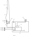
- the wind turbine 10 is provided with a blade load sensor system in accordance with an embodiment of the invention, features of which will now be described with reference to Figure 2 .
- the blade 20 is shown as having an aerofoil profile 22 provided by an outer shell 24 defining a substantially hollow interior 26.
- the aerofoil profile 22 of the blade 20 blends into a substantially cylindrical section at its root end 28 where the blade 20 is coupled to the hub 18.
- the blade 20 includes a load sensor package 30a located near to the root end 28 of the blade 20.
- the load sensor package 30a comprises a load sensor 32a and a temperature sensor 34a.
- the temperature sensor 34a is configured to measure the temperature of the blade 20 in the vicinity of the load sensor 32a to allow the load sensor output signal to be compensated for temperature effects using data from the temperature sensor 34a.
- the load sensor package 30a may be bonded to the interior surface of the blade 20 or alternatively, the sensor package 30a may be embedded within the structure of the shell 24 or bonded to the exterior surface.
- the load sensor 32a and the temperature sensor 34a are an integrated package, it is also envisaged that the load and temperature sensors could be physically separated from one another.
- the load sensor package 30a is connected to a data bus 36 so that any subsystem connected to that data bus 36 may pick off the output signals of the load sensor package 30a.
- One such subsystem is a processing unit 38.
- the role of the processing unit 38 is to pick off the temperature measurement signal provided by the temperature sensor 34a of the load sensor package 30a from the data bus 36 and to output a verified or corrected temperature signal or, indeed, load signal.
- the processing unit 38 is operable to perform diagnostics on the sensor packages in order to identify one or more faulty temperature sensors, and to take action to ensure that the resulting temperature sensor and/or load sensor signals are accurate, as will be explained.
- the processing unit 38 outputs the verified or corrected temperature signal and load signal to the data bus 36 so that it is available to any connected subsystem of the wind turbine 10.
- the processing unit 38 may alternatively be configured to output the verified or corrected temperature signal and load signal directly to any relevant subsystem.
- a single processing unit 38 is common to all the load sensor packages 30, but, alternatively, a dedicated processing unit could be provided for each of the packages 30. Also, although only a single load sensor package 30 is shown with respect to each blade 20, it should be appreciated more than one load sensor package 30 may be built into each blade, depending on the application.
- the processing unit 38 is interfaced with the load sensor package 30 so as to receive the raw temperature measurement signal from the temperature sensor 34 and is configured to perform a verification or correction function so that the temperature signal that is output from the processing unit 38 is credible.
- the processing unit 38 is arranged to monitor (i.e. receive data signals related to) one or more wind turbine parameters.
- the one or more wind turbine parameters may include, but are not restricted to: the nacelle temperature and the ambient temperature.
- the wind turbine 10 is provided with various sensors which provide data signals to the processing unit 38. The skilled person will appreciate that the sensors may provide signals to the processing unit 38 via a wired or wireless connection, as appropriate.
- the nacelle 12 includes an interior temperature sensor 40 to measure the temperature inside the nacelle 12.
- the interior temperature sensor 40 may be part of a nacelle temperature control system which maintains the temperature inside the nacelle 12 within acceptable operational limits to prevent the power generation equipment inside the nacelle 12 from overheating.
- the nacelle 12 also includes an ambient temperature sensor 42 to measure the ambient air temperature in the vicinity of the wind turbine 10.
- the ambient temperature sensor 42 is shown as part of a meteorological system (or ⁇ met mast') mounted to the nacelle, but the ambient temperature sensor 42 may be provided as simply a temperature sensing package mounted on any suitable component of the wind turbine 10 or provided remotely from the wind turbine 10.
- the processing unit 38 may receive information relating to the ambient air temperature from an external meteorological information source that may be accessed, for example, via a conventional wireless connection.
- the role of the processing unit 38 is to output blade load signals onto the data bus 36 which are acceptably accurate to be used for various applications run by the other subsystems of the wind turbine. For example, applications may be run that function to reduce blade loading, and therefore rely on blade load signals that are an accurate reflection of the actual load on the blade. Since the temperature of the load sensor packages 30 can affect the output load signals, the processing unit 38 is operable to compensate the load sensor signals to account for the prevailing temperature as measured by the associated temperature sensor. However, it is possible that the temperature sensor will fail, or may drift, such that the load sensor signal is not compensated for correctly which will mean that downstream functions that rely on accurate load sensor signals will also be adversely affected.
- the processing unit 38 is provided with functionality that monitors the output of the temperature sensors of the load sensor packages and acts to diagnose if any of those sensors are outputting faulty signals. Various actions can be taken if a temperature sensor is recognised as being faulty. For example, the load sensor readings associated with the faulty temperature sensor can be disregarded or, alternatively, a substitute temperature value can be used in the pace of the temperature measurement from the faulty sensor.
- the processing unit 38 comprises a temperature estimator or 'temperature estimation module' 44, a comparator 46, a temperature output module 48, and a load calculation module 49, as are represented as functional blocks in Figure 3 .
- the processing unit 38 also includes a memory area on which suitable software is stored and an execution environment to run the control software.
- the functional blocks illustrate a specific functionality of the processing unit 38 and, as such, they may be implemented on hardware, software or firmware, either within the same processing environment or on a distributed processing architecture. That is to say, the functional architecture illustrated in Figure 3 is not intended to limit the invention to a specific hardware or software architecture, platform or processing environment.
- the system architecture discussed here is used merely as an example to illustrate the technical functionality of the invention and the invention may be implemented by a system having a different specific architecture.
- the load calculation module 49 is responsible for a determining a value for blade load for each of the blades of the wind turbine based on measurements from the respective blade load sensors 32a-c and respective temperature values that it receives from the temperature output module 48. However, notably, the temperature values that are received from the temperature output module 48 are validated in that they are ensured that they are an acceptably accurate indication of the actual temperature within the respective blade. Together, the temperature estimation module 44, the comparator 46 and the temperature output module 48 provide this functionality, as will now be explained.
- the temperature estimation module 44 is shown in Figure 3 as receiving data input signals from one or more sensors 50. As illustrated in Figure 2 , these data input signals may correspond to the ambient temperature and the nacelle temperature.
- the role of the temperature estimation module 44 is to output an estimated temperature of each blade 20 (in the vicinity of the load sensor package 30) based on the input signals.
- the temperature estimation module 44 implements a blade temperature model. In doing so, the temperature estimation module 44 makes the assumption that the temperature of each blade is the same. Therefore, the following description refers to a single estimated blade temperature.
- the comparator 46 receives data input signals from the temperature estimation module 44, i.e. the estimated blade temperature, and also the measured blade temperatures from the temperature sensors 34a-c. Note that for clarity purposes the temperature data is shown in Figure 3 as direct input from the sensors 34a-c, but the same data could also be input to the comparator 46 from the data bus 36.
- the role of the comparator 46 is to identify whether any of the blade temperature signals from the sensors 34a-c are invalid and, if so, to generate a fault signal based at least in part on a comparison of the three measured blade temperature signals and the estimated blade temperature. As will be described in further detail, the fault signal indicates when there is a fault in respect of one or more of the temperature sensors 34.
- the role of the temperature output module 48 is to provide a verified or corrected temperature signal for each blade 20.
- the verified or corrected blade temperature signals are determined based on the measurements of the blade temperature sensors 34 and/or the estimated blade temperature, as will be explained in more detail.
- the blade load sensor system described above allows credible blade temperature signals and, moreover, blade load signals, to be generated for each blade 20 of the wind turbine 10.
- wind turbine parameters such as the ambient temperature and the nacelle temperature are measured by the relevant sensors 50.
- the temperature estimator 44 receives the relevant sensor outputs and implements a blade temperature model, as mentioned above. The temperature estimator 44 then outputs an estimated blade temperature at step 104.
- the temperatures of the blades 20 are measured by the temperature sensors 34 mounted on the blades 20.
- the comparator 46 receives signals from the temperature estimator 44 and the blade temperature sensors 34 and compares each blade temperature measurement to the estimated blade temperature. At step 110, the comparator generates a fault signal based on these comparisons.
- the comparator 46 may be configured to perform various processes in order to perform this comparison. Some examples of comparison processes that may be performed will now be described.
- the comparator 46 determines that a temperature sensor 34 has a fault if the difference between the temperature measured by that sensor 34 and the estimated blade temperature exceeds a predetermined threshold value. The comparator then generates a fault signal accordingly, indicating the binary fault status of each temperature sensor 34.
- the comparison process described above is relatively simple and advantageously minimises the processing burden on the comparator 46. It is envisaged, however, in other embodiments that a more sophisticated analysis of the blade temperature sensor outputs may be performed. Specifically, the following example allows the comparator 46 to detect the presence of a faulty temperature sensor, and isolate which sensor is faulty, taking account of the possibility that the temperature estimator may be faulty, as will be explained.
- the comparator 46 performs six bilateral comparisons: one between each blade temperature measurement and the estimated blade temperature, as in the example above; and one between each pair of blade temperature measurements. Each of these comparisons results in a difference signal indicating the difference in value between the two compared temperature signals.
- the comparator 46 analyses these signals to generate an appropriate fault signal. So, if one of the temperature sensors is faulty, its temperature reading will differ appreciable from the readings of the other temperature sensors, but will also differ appreciable from the estimated temperature from the temperature estimation module 44. Alternatively, if the temperature estimation module 44 has developed a fault, the temperature measurements from the temperature sensors will be close in value, but will be expected to differ appreciably from the estimated temperature.
- the difference signals may be analysed by comparison with a predetermined threshold, similar to the process described above in relation to the previous example.
- an appropriate statistical method may be employed to increase the sensitivity of the system without prompting an increase in erroneous indications of faulty sensors.
- the difference signals are analysed in accordance with the principle of the up/down counter or ⁇ leaky bucket' model although other methods such as cumulative sum (CUSUM) or the generalised likelihood ratio test (GLRT) are equally applicable.
- CCSUM cumulative sum
- GLRT generalised likelihood ratio test
- each difference signal is communicated to a counter which can change state in either the up or down direction under the control of an up or down selector input.
- the selector input When the value of the difference signal is above a predetermined threshold, the selector input is considered to be in the up state and the counter increments its value. Conversely, when the value of the difference signal is below a predetermined threshold, the selector input is considered to be in the down state and the counter decrements its value.
- the counter also has a maximum and minimum value at which up state and down state selector inputs respectively have no effect.
- the value of the up/down counter increases or decreases depending on the difference signal input.
- the counter When the value of the up/down counter exceeds a predetermined threshold, the counter generates an alarm signal that indicates that the comparison associated with that counter has resulted in a significant difference.
- the appropriate values of the various predetermined thresholds are determined based on the characteristics of the sensors and of the required sensitivity of the fault detection. These values may be stored in the memory area of the processing unit to be accessed by the comparator 46 in order to implement the up/down counter analysis.
- the comparator 46 then generates a fault signal based on the outputs of all of the up/down counters. If the counters associated with all three comparisons involving a certain blade temperature sensor are each generating an alarm signal, then the comparator 46 will determine that that sensor is faulty and will generate a fault signal accordingly. Similarly, if the counters associated with all three comparisons involving the estimated blade temperature are generating an alarm signal, then the comparator will determine that the temperature estimator is faulty. Thus, the comparator is able to detect and isolate a faulty temperature sensor and generate a fault signal accordingly.
- the temperature output module 48 outputs verified or corrected temperature signals for each blade 20 based on the fault signal generated by the comparator 46 and the measured and estimated blade temperatures.
- the corrected temperature values may be output to the data bus 36 where they can be used by other subsystems of the wind turbine, if appropriate. If the fault signal indicates that a particular sensor 34 is working correctly, then the temperature output module 48 simply outputs a temperature signal for the corresponding blade 20 that is the same as the temperature measured by the temperature sensor 34. Thus, the output of the sensors 34 are verified. These credible temperature signals are output to the load calculation module 49 where they are be used to determine temperature-corrected values for the loads experienced by the blades 20.
- the temperature output module 48 provides a corrected temperature signal for the corresponding blade 20.
- the corrected temperature signal is the estimated blade temperature. In other embodiments, the corrected temperature may be the average value of the working blade temperature sensors.
- the load calculation module 49 can be considered to receive a correct or verified value of temperature in order to calculate a temperature-compensated load signal for each blade 20 of the wind turbine.
- the load calculation module 49 calculates the respective load values at step 114.
- the process in which the load calculation module 49 calculates the temperature- compensated load signal based on the raw load signal from the load sensor 32 and the temperature signal from the temperature output module 48 is a technique that would be well known to the skilled person, for example based on sensor characteristic curves, and so it will not be described in detail here.
- the determination of whether one of the blade temperature sensors is faulty is based at least in part on the output of the temperature estimation module 44.
- the temperature estimation module 44 may implement various forms of temperature model depending on the accuracy of the temperature estimation that is required.
- the temperature estimation module 44 relates the estimated temperature directly to the ambient temperature by assuming that the blade temperature is equal to the ambient temperature in the vicinity of the wind turbine 10.
- the temperature estimation module 44 there is only one data input signal to the temperature estimation module 44, namely ambient temperature data from the ambient temperature sensor 42, such that the output of the temperature estimation module 44 is the same as the input.
- the blade load sensor system it is not necessary for the blade load sensor system to include a nacelle temperature sensor 40.
- a simple and relatively inexpensive blade load sensor system can be provided.
- the estimated blade temperature could be used as the estimated blade temperature.
- the temperature measurement from one of the other temperature sensors from within the same blade could be used as the estimated temperature, or, indeed, the temperature measurement from a sensor mounted in one of the other blades of the wind turbine, based on the understanding that the blade temperatures should be about the same, given the common ambient environment.
- the temperature measurement of another wind turbine could be used for the estimated temperature.
- the model described here estimates the temperature in the hollow interior 26 of the blade 20. This gives a good estimate of the temperature of the blade 20 in the vicinity of the load sensor package 30 for embodiments where the load sensor package 30 is bonded to the interior surface of the blade 20. However, this model is also applicable to embodiments where the load sensor package 30 is provided elsewhere in the blade 20 since the cavity 26 and shell 24 of the blade 20 are in good thermal contact and so share a similar temperature.
- Newton's law of cooling allows the quantity of heat transferred to or from the blade 20 to be quantified.
- T b T i + 1 cm ⁇ T n ⁇ T b e ⁇ h n A n t + T b ⁇ T a e ⁇ h b A b t
- a blade temperature model is provided that relates the temperature of the blade 20 in the vicinity of the load sensor package 30 to the ambient temperature (as measured by the ambient temperature sensor 42) and the nacelle temperature (as measured by the nacelle temperature sensor 40).
- the temperature estimation module 44 may implement the above model by performing one or more algorithms to calculate a value for the estimated blade temperature.
- the values of the relevant constants may be stored in the memory area of the processing unit 38.
- the estimated blade temperature may be calculated for a range of ambient and nacelle temperatures ahead of time and stored in the memory area of the processing unit 38 as a data set that correlates values of the ambient and nacelle temperature to values of the estimated blade temperature, i.e. a look-up table.
- the temperature estimation module 44 can then consult this look-up table to determine the estimated blade temperature based on the measured ambient and nacelle temperatures at that moment in time.
- the temperature estimation module may implement other blade temperature models. These models may include the effects of any other factors affecting the temperature of the blade 20 as is appropriate for the configuration of the wind turbine 10 and the required accuracy of the temperature estimation.
- a blade sensor system according to an embodiment of the invention may be installed in a blade including an anti-icing system, as indicated by the dashed box in Figure 2 , and indicated with the reference 200.
- the anti-icing system 200 prevents ice from forming on the surfaces of the blade shell 24 by circulating hot air around the blade cavity 26 when required.
- the temperature module will implement a blade temperature model that accounts for the effect of the heat transferred to the blade cavity 26 by the anti-icing system 200.
- the anti-icing system 200 may include a status indicator that provides a signal to the processing unit 38 indicating the heat transferred to the blade cavity 26 by the anti-icing system 200.
- the blade temperature model will be constructed empirically in full or in part.
- the necessary experimental data could be acquired from a working wind turbine in situ or from controlled experiments conducted in a laboratory or workshop.
Landscapes
- Engineering & Computer Science (AREA)
- Physics & Mathematics (AREA)
- General Physics & Mathematics (AREA)
- Chemical & Material Sciences (AREA)
- Life Sciences & Earth Sciences (AREA)
- Sustainable Development (AREA)
- Sustainable Energy (AREA)
- Combustion & Propulsion (AREA)
- Mechanical Engineering (AREA)
- General Engineering & Computer Science (AREA)
- Analytical Chemistry (AREA)
- Wind Motors (AREA)
Claims (18)
- Système de capteurs pour une éolienne (10), comprenant :un capteur de charge de pale (32a) ;un capteur de température de pale (34a) configuré pour fournir une mesure de température d'une pale associée ; etun module de calcul de charge (49) configuré pour émettre une valeur de charge de pale corrigée en température, caractérisé par :
une unité de traitement (38) interfacée avec le capteur de température et incluant :un estimateur de température (44) configuré pour déterminer une température estimée de la pale d'éolienne sur la base d'au moins un paramètre d'éolienne ; etun comparateur (46) configuré pour générer un signal de panne sur la base d'une comparaison entre la mesure de température de pale et la température de pale estimée,dans lequel l'estimateur de température (44) réalise une modélisation de la température de la pale dans le voisinage du capteur de température sur la base de l'énergie thermique nette transférée à l'intérieur de la pale. - Système selon la revendication 1, dans lequel l'estimateur de température (44) établit directement un rapport entre la température estimée de la pale dans le voisinage du capteur de température (34a) et le au moins un paramètre d'éolienne.
- Système selon la revendication 2, dans lequel l'estimateur de température (44) établit un rapport entre la température estimée de la pale dans le voisinage du capteur de température (34a) et une mesure de température d'un composant ou d'une région de l'éolienne distants du capteur de température.
- Système selon la revendication 3, dans lequel l'estimateur de température (44) établit un rapport entre la température estimée de la pale dans le voisinage du capteur de température (34a) et la température de l'environnement ambiant.
- Système selon une quelconque revendication précédente, dans lequel le comparateur (46) est configuré pour générer un signal de panne dans des circonstances où la différence entre la mesure de température de pale et la température de pale estimée dépasse un seuil prédéterminé.
- Système selon les revendications 1 à 4, dans lequel le comparateur (46) est configuré pour générer un signal de panne sur la base de la sortie d'une technique statistique pour évaluer la différence entre la mesure de température de pale et la température de pale estimée.
- Système selon une quelconque revendication précédente, dans lequel le capteur de température de pale (34a) fait partie d'un ensemble de capteurs de charge de pale.
- Système selon une quelconque revendication précédente, dans lequel le capteur de température de pale (34a) est intégré à une extrémité de pied de la pale d'éolienne associée.
- Système selon une quelconque revendication précédente, incluant une pluralité de capteurs de température de pale (34a, 34b, 34c), parmi lesquels chacun est configuré pour fournir une mesure de température de pale respective.
- Système selon la revendication 9, dans lequel le comparateur (46) est configuré pour comparer chaque mesure de température de pale à une température de pale estimée respective, et dans lequel un signal de panne respectif généré par le comparateur (46) est basé sur ces comparaisons.
- Système selon la revendication 9 ou la revendication 10, dans lequel le comparateur (46) est configuré pour isoler l'un des capteurs de température de pale (34a, 34b, 34c) comme en panne en réalisant une comparaison de mesures de température de pale.
- Système selon une quelconque revendication précédente, dans lequel l'unité de traitement (38) est configurée pour déterminer une mesure de température corrigée quant à au moins un capteur de température (34a, 34b, 34c) dans des circonstances où un signal de panne est généré.
- Système selon la revendication 11, dans lequel la mesure de température corrigée est basée sur la température estimée associée déterminée par l'estimateur de température (44).
- Système selon la revendication 12, lorsqu'elle dépend de l'une quelconque des revendications 9 à 11, dans lequel la mesure de température corrigée est basée sur les mesures de température d'au moins un des autres capteurs de température (34a, 34b, 34c).
- Système selon les revendications 12 à 14, dans lequel l'unité de calcul de charge (49) est configurée pour déterminer une valeur de charge corrigée en température sur la base d'une mesure de température corrigée en cas de signal de panne généré.
- Procédé d'évaluation d'un système de capteurs pour une éolienne (10), le procédé comprenant :une détermination d'une mesure de température d'une pale d'éolienne (20) ; etune détermination d'une mesure de charge corrigée en température d'une pale d'éolienne (20) ;caractérisé par :une détermination d'une température estimée de la pale d'éolienne (20) sur la base d'au moins un paramètre d'éolienne ;une modélisation de la température de la pale dans le voisinage du capteur de température sur la base de l'énergie thermique nette transférée à l'intérieur de la pale ; etune génération d'un signal de panne sur la base d'une comparaison entre la mesure de température de pale et la température de pale estimée.
- Produit programme d'ordinateur téléchargeable depuis un réseau de communication et/ou stocké sur un support lisible par machine, comprenant des instructions de code de programme qui, lorsque le programme est exécuté par un ordinateur, amènent l'ordinateur à mettre en oeuvre la revendication de procédé 16.
- Support lisible par machine ayant stocké sur celui-ci le produit programme d'ordinateur selon la revendication 17.
Applications Claiming Priority (2)
| Application Number | Priority Date | Filing Date | Title |
|---|---|---|---|
| DKPA201570388 | 2015-06-24 | ||
| PCT/DK2016/050196 WO2016206692A1 (fr) | 2015-06-24 | 2016-06-17 | Système de détection de charge de pale pour une éolienne |
Publications (3)
| Publication Number | Publication Date |
|---|---|
| EP3314120A1 EP3314120A1 (fr) | 2018-05-02 |
| EP3314120B1 true EP3314120B1 (fr) | 2023-06-07 |
| EP3314120C0 EP3314120C0 (fr) | 2023-06-07 |
Family
ID=56203064
Family Applications (1)
| Application Number | Title | Priority Date | Filing Date |
|---|---|---|---|
| EP16731792.4A Active EP3314120B1 (fr) | 2015-06-24 | 2016-06-17 | Système de détection de charge de pale pour une éolienne |
Country Status (5)
| Country | Link |
|---|---|
| US (1) | US10655606B2 (fr) |
| EP (1) | EP3314120B1 (fr) |
| CN (1) | CN107787406B (fr) |
| ES (1) | ES2948868T3 (fr) |
| WO (1) | WO2016206692A1 (fr) |
Families Citing this family (13)
| Publication number | Priority date | Publication date | Assignee | Title |
|---|---|---|---|---|
| ES2698561T3 (es) * | 2015-01-29 | 2019-02-05 | Vestas Wind Sys As | Controladores para carga parcial y plena de una turbina eólica |
| EP3314120B1 (fr) | 2015-06-24 | 2023-06-07 | Vestas Wind Systems A/S | Système de détection de charge de pale pour une éolienne |
| ES2924411T3 (es) * | 2015-06-30 | 2022-10-06 | Vestas Wind Sys As | Sistema de detección de carga de pala para un aerogenerador |
| DK3625528T3 (da) * | 2017-05-18 | 2022-06-13 | Gen Electric | System og fremgangsmåde til estimering af motortemperatur på et pitch-system af en vindmølle |
| ES2880679T3 (es) * | 2017-05-26 | 2021-11-25 | Vestas Wind Sys As | Mejoras relacionadas con sistemas de detección de ángulo de rotor de turbina eólica |
| JP6697494B2 (ja) * | 2018-02-01 | 2020-05-20 | ファナック株式会社 | 異常判別装置、プログラム、異常判別システム及び異常判別方法 |
| WO2020216424A1 (fr) * | 2019-04-26 | 2020-10-29 | Vestas Wind Systems A/S | Dispositif de commande et procédé destinés à une éolienne |
| FR3104710B1 (fr) * | 2019-12-12 | 2022-12-30 | Schneider Electric Ind Sas | Méthodes et systèmes de surveillance d’installations électriques |
| EP3889423A1 (fr) * | 2020-04-02 | 2021-10-06 | Siemens Gamesa Renewable Energy A/S | Procédé et système de commande du fonctionnement d'éoliennes |
| CN115768980B (zh) | 2020-06-04 | 2025-11-25 | 维斯塔斯风力系统有限公司 | 风力涡轮机中的温度估计 |
| CN113969870B (zh) * | 2020-07-23 | 2023-07-25 | 北京金风科创风电设备有限公司 | 用于风力发电机组估计器的监测方法及其装置 |
| CN112046761B (zh) * | 2020-08-04 | 2021-10-15 | 中国空气动力研究与发展中心计算空气动力研究所 | 一种基于统计检验和滤波的飞机结冰在线探测方法 |
| PL4008900T3 (pl) * | 2020-12-03 | 2025-05-19 | General Electric Renovables España S.L. | Czujniki obciążenia w turbinach wiatrowych |
Family Cites Families (10)
| Publication number | Priority date | Publication date | Assignee | Title |
|---|---|---|---|---|
| US3588265A (en) * | 1968-04-19 | 1971-06-28 | Westinghouse Electric Corp | System and method for providing steam turbine operation with improved dynamics |
| CA2426711C (fr) * | 2002-05-02 | 2009-11-17 | General Electric Company | Centrale eolienne, mecanisme de commande de centrale eolienne et methode d'exploitation d'une centrale eolienne |
| EP1709416B1 (fr) | 2004-01-23 | 2018-03-07 | LM Wind Power International Technology II ApS | Dispositif comprenant un systeme concu pour etre utilise dans la compensation thermique de mesures de contrainte dans des structures renforcees par des fibres |
| DE102005017054B4 (de) * | 2004-07-28 | 2012-01-05 | Igus - Innovative Technische Systeme Gmbh | Verfahren und Vorrichtung zur Überwachung des Zustandes von Rotorblättern an Windkraftanlagen |
| GB2440954B (en) | 2006-08-18 | 2008-12-17 | Insensys Ltd | Structural monitoring |
| US20110135474A1 (en) | 2010-04-29 | 2011-06-09 | Matthias Thulke | Method for temperature calibration of blade strain gauges and wind turbine rotor blade containing strain gauges |
| US9399983B2 (en) | 2010-12-30 | 2016-07-26 | Lm Wp Patent Holding A/S | Wind turbine blade with cross-sectional sensors |
| EP2551982B1 (fr) * | 2011-07-27 | 2013-09-25 | Siemens Aktiengesellschaft | Surveillance thermique d'un convertisseur |
| KR101250206B1 (ko) | 2011-09-23 | 2013-04-03 | 한국전력공사 | 풍력발전단지 블레이드 감시 시스템 및 방법 |
| EP3314120B1 (fr) | 2015-06-24 | 2023-06-07 | Vestas Wind Systems A/S | Système de détection de charge de pale pour une éolienne |
-
2016
- 2016-06-17 EP EP16731792.4A patent/EP3314120B1/fr active Active
- 2016-06-17 ES ES16731792T patent/ES2948868T3/es active Active
- 2016-06-17 CN CN201680036883.9A patent/CN107787406B/zh active Active
- 2016-06-17 WO PCT/DK2016/050196 patent/WO2016206692A1/fr not_active Ceased
- 2016-06-17 US US15/579,097 patent/US10655606B2/en active Active
Also Published As
| Publication number | Publication date |
|---|---|
| WO2016206692A1 (fr) | 2016-12-29 |
| CN107787406A (zh) | 2018-03-09 |
| US20180171983A1 (en) | 2018-06-21 |
| EP3314120C0 (fr) | 2023-06-07 |
| US10655606B2 (en) | 2020-05-19 |
| ES2948868T3 (es) | 2023-09-20 |
| EP3314120A1 (fr) | 2018-05-02 |
| CN107787406B (zh) | 2021-01-26 |
Similar Documents
| Publication | Publication Date | Title |
|---|---|---|
| EP3314120B1 (fr) | Système de détection de charge de pale pour une éolienne | |
| EP3314226B1 (fr) | Système de détection de charge de pale pour une éolienne | |
| CN101298864B (zh) | 运行风力涡轮机的方法和风力涡轮机 | |
| EP3739342B1 (fr) | Surveillance pronostique de capteurs complémentaires de système de données d'air | |
| Oh et al. | A novel method and its field tests for monitoring and diagnosing blade health for wind turbines | |
| EP1936184B1 (fr) | Détection de glace basée sur l'anémométrie | |
| US8951011B2 (en) | Wind turbine and a method for monitoring a wind turbine | |
| CN107820541B (zh) | 风力涡轮机叶片载荷传感系统 | |
| EP3062131B1 (fr) | Procédé de détection de détériorations de pales de turbine éolienne et éolienne | |
| CN105604806B (zh) | 风力发电机的塔架状态监测方法和系统 | |
| US11098698B2 (en) | System and method for auto-calibrating a load sensor system of a wind turbine | |
| JP6610987B2 (ja) | 異常診断方法及び異常診断システム | |
| US20180157249A1 (en) | Abnormality Detecting Apparatus | |
| US10844842B2 (en) | Abnormality monitoring apparatus and abnormality monitoring method for wind farm | |
| CA2963917A1 (fr) | Duree utile restante predite par une composante physique | |
| EP3165469A1 (fr) | Système et procédé d'assistance de réglage de fluide d'un amortisseur de train d'atterrissage d'aéronef | |
| US20120253559A1 (en) | Method And Device For Automatically Detecting Erroneous Air Data On An Aircraft | |
| WO2012069843A1 (fr) | Pales de rotor de turbine éolienne | |
| TWI647575B (zh) | Fatigue deterioration diagnosis method of windmill and windmill, operation control method of windmill | |
| WO2018153517A1 (fr) | Étalonnage d'un capteur de vent d'une éolienne | |
| CN114450647A (zh) | 技术系统的诊断 | |
| CN117759490A (zh) | 一种风电机组叶片故障监测方法及系统 | |
| BR102019026481B1 (pt) | Sistema de gerenciamento de estado de aeronave, e, método para identificar um sinal anômalo |
Legal Events
| Date | Code | Title | Description |
|---|---|---|---|
| STAA | Information on the status of an ep patent application or granted ep patent |
Free format text: STATUS: THE INTERNATIONAL PUBLICATION HAS BEEN MADE |
|
| PUAI | Public reference made under article 153(3) epc to a published international application that has entered the european phase |
Free format text: ORIGINAL CODE: 0009012 |
|
| STAA | Information on the status of an ep patent application or granted ep patent |
Free format text: STATUS: REQUEST FOR EXAMINATION WAS MADE |
|
| 17P | Request for examination filed |
Effective date: 20171220 |
|
| AK | Designated contracting states |
Kind code of ref document: A1 Designated state(s): AL AT BE BG CH CY CZ DE DK EE ES FI FR GB GR HR HU IE IS IT LI LT LU LV MC MK MT NL NO PL PT RO RS SE SI SK SM TR |
|
| AX | Request for extension of the european patent |
Extension state: BA ME |
|
| DAV | Request for validation of the european patent (deleted) | ||
| DAX | Request for extension of the european patent (deleted) | ||
| STAA | Information on the status of an ep patent application or granted ep patent |
Free format text: STATUS: EXAMINATION IS IN PROGRESS |
|
| 17Q | First examination report despatched |
Effective date: 20200318 |
|
| GRAP | Despatch of communication of intention to grant a patent |
Free format text: ORIGINAL CODE: EPIDOSNIGR1 |
|
| STAA | Information on the status of an ep patent application or granted ep patent |
Free format text: STATUS: GRANT OF PATENT IS INTENDED |
|
| INTG | Intention to grant announced |
Effective date: 20221108 |
|
| GRAS | Grant fee paid |
Free format text: ORIGINAL CODE: EPIDOSNIGR3 |
|
| GRAA | (expected) grant |
Free format text: ORIGINAL CODE: 0009210 |
|
| STAA | Information on the status of an ep patent application or granted ep patent |
Free format text: STATUS: THE PATENT HAS BEEN GRANTED |
|
| AK | Designated contracting states |
Kind code of ref document: B1 Designated state(s): AL AT BE BG CH CY CZ DE DK EE ES FI FR GB GR HR HU IE IS IT LI LT LU LV MC MK MT NL NO PL PT RO RS SE SI SK SM TR |
|
| REG | Reference to a national code |
Ref country code: GB Ref legal event code: FG4D |
|
| REG | Reference to a national code |
Ref country code: CH Ref legal event code: EP Ref country code: AT Ref legal event code: REF Ref document number: 1575806 Country of ref document: AT Kind code of ref document: T Effective date: 20230615 Ref country code: DE Ref legal event code: R096 Ref document number: 602016079898 Country of ref document: DE |
|
| U01 | Request for unitary effect filed |
Effective date: 20230627 |
|
| U07 | Unitary effect registered |
Designated state(s): AT BE BG DE DK EE FI FR IT LT LU LV MT NL PT SE SI Effective date: 20230703 |
|
| U20 | Renewal fee for the european patent with unitary effect paid |
Year of fee payment: 8 Effective date: 20230704 |
|
| REG | Reference to a national code |
Ref country code: ES Ref legal event code: FG2A Ref document number: 2948868 Country of ref document: ES Kind code of ref document: T3 Effective date: 20230920 |
|
| REG | Reference to a national code |
Ref country code: LT Ref legal event code: MG9D |
|
| PG25 | Lapsed in a contracting state [announced via postgrant information from national office to epo] |
Ref country code: NO Free format text: LAPSE BECAUSE OF FAILURE TO SUBMIT A TRANSLATION OF THE DESCRIPTION OR TO PAY THE FEE WITHIN THE PRESCRIBED TIME-LIMIT Effective date: 20230907 |
|
| PG25 | Lapsed in a contracting state [announced via postgrant information from national office to epo] |
Ref country code: RS Free format text: LAPSE BECAUSE OF FAILURE TO SUBMIT A TRANSLATION OF THE DESCRIPTION OR TO PAY THE FEE WITHIN THE PRESCRIBED TIME-LIMIT Effective date: 20230607 Ref country code: HR Free format text: LAPSE BECAUSE OF FAILURE TO SUBMIT A TRANSLATION OF THE DESCRIPTION OR TO PAY THE FEE WITHIN THE PRESCRIBED TIME-LIMIT Effective date: 20230607 Ref country code: GR Free format text: LAPSE BECAUSE OF FAILURE TO SUBMIT A TRANSLATION OF THE DESCRIPTION OR TO PAY THE FEE WITHIN THE PRESCRIBED TIME-LIMIT Effective date: 20230908 |
|
| PG25 | Lapsed in a contracting state [announced via postgrant information from national office to epo] |
Ref country code: SK Free format text: LAPSE BECAUSE OF FAILURE TO SUBMIT A TRANSLATION OF THE DESCRIPTION OR TO PAY THE FEE WITHIN THE PRESCRIBED TIME-LIMIT Effective date: 20230607 |
|
| PG25 | Lapsed in a contracting state [announced via postgrant information from national office to epo] |
Ref country code: IS Free format text: LAPSE BECAUSE OF FAILURE TO SUBMIT A TRANSLATION OF THE DESCRIPTION OR TO PAY THE FEE WITHIN THE PRESCRIBED TIME-LIMIT Effective date: 20231007 |
|
| PG25 | Lapsed in a contracting state [announced via postgrant information from national office to epo] |
Ref country code: SM Free format text: LAPSE BECAUSE OF FAILURE TO SUBMIT A TRANSLATION OF THE DESCRIPTION OR TO PAY THE FEE WITHIN THE PRESCRIBED TIME-LIMIT Effective date: 20230607 Ref country code: SK Free format text: LAPSE BECAUSE OF FAILURE TO SUBMIT A TRANSLATION OF THE DESCRIPTION OR TO PAY THE FEE WITHIN THE PRESCRIBED TIME-LIMIT Effective date: 20230607 Ref country code: RO Free format text: LAPSE BECAUSE OF FAILURE TO SUBMIT A TRANSLATION OF THE DESCRIPTION OR TO PAY THE FEE WITHIN THE PRESCRIBED TIME-LIMIT Effective date: 20230607 Ref country code: IS Free format text: LAPSE BECAUSE OF FAILURE TO SUBMIT A TRANSLATION OF THE DESCRIPTION OR TO PAY THE FEE WITHIN THE PRESCRIBED TIME-LIMIT Effective date: 20231007 Ref country code: CZ Free format text: LAPSE BECAUSE OF FAILURE TO SUBMIT A TRANSLATION OF THE DESCRIPTION OR TO PAY THE FEE WITHIN THE PRESCRIBED TIME-LIMIT Effective date: 20230607 |
|
| REG | Reference to a national code |
Ref country code: CH Ref legal event code: PL |
|
| PG25 | Lapsed in a contracting state [announced via postgrant information from national office to epo] |
Ref country code: PL Free format text: LAPSE BECAUSE OF FAILURE TO SUBMIT A TRANSLATION OF THE DESCRIPTION OR TO PAY THE FEE WITHIN THE PRESCRIBED TIME-LIMIT Effective date: 20230607 |
|
| REG | Reference to a national code |
Ref country code: DE Ref legal event code: R097 Ref document number: 602016079898 Country of ref document: DE |
|
| PG25 | Lapsed in a contracting state [announced via postgrant information from national office to epo] |
Ref country code: MC Free format text: LAPSE BECAUSE OF FAILURE TO SUBMIT A TRANSLATION OF THE DESCRIPTION OR TO PAY THE FEE WITHIN THE PRESCRIBED TIME-LIMIT Effective date: 20230607 |
|
| REG | Reference to a national code |
Ref country code: IE Ref legal event code: MM4A |
|
| PG25 | Lapsed in a contracting state [announced via postgrant information from national office to epo] |
Ref country code: MC Free format text: LAPSE BECAUSE OF FAILURE TO SUBMIT A TRANSLATION OF THE DESCRIPTION OR TO PAY THE FEE WITHIN THE PRESCRIBED TIME-LIMIT Effective date: 20230607 |
|
| PLBE | No opposition filed within time limit |
Free format text: ORIGINAL CODE: 0009261 |
|
| STAA | Information on the status of an ep patent application or granted ep patent |
Free format text: STATUS: NO OPPOSITION FILED WITHIN TIME LIMIT |
|
| PG25 | Lapsed in a contracting state [announced via postgrant information from national office to epo] |
Ref country code: IE Free format text: LAPSE BECAUSE OF NON-PAYMENT OF DUE FEES Effective date: 20230617 |
|
| PG25 | Lapsed in a contracting state [announced via postgrant information from national office to epo] |
Ref country code: IE Free format text: LAPSE BECAUSE OF NON-PAYMENT OF DUE FEES Effective date: 20230617 Ref country code: CH Free format text: LAPSE BECAUSE OF NON-PAYMENT OF DUE FEES Effective date: 20230630 |
|
| 26N | No opposition filed |
Effective date: 20240308 |
|
| U20 | Renewal fee for the european patent with unitary effect paid |
Year of fee payment: 9 Effective date: 20240625 |
|
| PGFP | Annual fee paid to national office [announced via postgrant information from national office to epo] |
Ref country code: GB Payment date: 20250617 Year of fee payment: 10 |
|
| PG25 | Lapsed in a contracting state [announced via postgrant information from national office to epo] |
Ref country code: CY Free format text: LAPSE BECAUSE OF FAILURE TO SUBMIT A TRANSLATION OF THE DESCRIPTION OR TO PAY THE FEE WITHIN THE PRESCRIBED TIME-LIMIT; INVALID AB INITIO Effective date: 20160617 |
|
| U20 | Renewal fee for the european patent with unitary effect paid |
Year of fee payment: 10 Effective date: 20250624 |
|
| PG25 | Lapsed in a contracting state [announced via postgrant information from national office to epo] |
Ref country code: HU Free format text: LAPSE BECAUSE OF FAILURE TO SUBMIT A TRANSLATION OF THE DESCRIPTION OR TO PAY THE FEE WITHIN THE PRESCRIBED TIME-LIMIT; INVALID AB INITIO Effective date: 20160617 |
|
| PGFP | Annual fee paid to national office [announced via postgrant information from national office to epo] |
Ref country code: ES Payment date: 20250710 Year of fee payment: 10 |
|
| PG25 | Lapsed in a contracting state [announced via postgrant information from national office to epo] |
Ref country code: TR Free format text: LAPSE BECAUSE OF FAILURE TO SUBMIT A TRANSLATION OF THE DESCRIPTION OR TO PAY THE FEE WITHIN THE PRESCRIBED TIME-LIMIT Effective date: 20230607 |