EP3314128B1 - Gebläse und lüftungsgruppe mit diesem gebläse - Google Patents
Gebläse und lüftungsgruppe mit diesem gebläse Download PDFInfo
- Publication number
- EP3314128B1 EP3314128B1 EP16745173.1A EP16745173A EP3314128B1 EP 3314128 B1 EP3314128 B1 EP 3314128B1 EP 16745173 A EP16745173 A EP 16745173A EP 3314128 B1 EP3314128 B1 EP 3314128B1
- Authority
- EP
- European Patent Office
- Prior art keywords
- fan
- hub
- axis
- rotation
- wall
- Prior art date
- Legal status (The legal status is an assumption and is not a legal conclusion. Google has not performed a legal analysis and makes no representation as to the accuracy of the status listed.)
- Active
Links
Images

Classifications
-
- F—MECHANICAL ENGINEERING; LIGHTING; HEATING; WEAPONS; BLASTING
- F04—POSITIVE - DISPLACEMENT MACHINES FOR LIQUIDS; PUMPS FOR LIQUIDS OR ELASTIC FLUIDS
- F04D—NON-POSITIVE-DISPLACEMENT PUMPS
- F04D25/00—Pumping installations or systems
- F04D25/02—Units comprising pumps and their driving means
- F04D25/08—Units comprising pumps and their driving means the working fluid being air, e.g. for ventilation
- F04D25/082—Units comprising pumps and their driving means the working fluid being air, e.g. for ventilation the unit having provision for cooling the motor
-
- F—MECHANICAL ENGINEERING; LIGHTING; HEATING; WEAPONS; BLASTING
- F04—POSITIVE - DISPLACEMENT MACHINES FOR LIQUIDS; PUMPS FOR LIQUIDS OR ELASTIC FLUIDS
- F04D—NON-POSITIVE-DISPLACEMENT PUMPS
- F04D29/00—Details, component parts, or accessories
- F04D29/40—Casings; Connections of working fluid
- F04D29/52—Casings; Connections of working fluid for axial pumps
- F04D29/522—Casings; Connections of working fluid for axial pumps especially adapted for elastic fluid pumps
- F04D29/526—Details of the casing section radially opposing blade tips
-
- F—MECHANICAL ENGINEERING; LIGHTING; HEATING; WEAPONS; BLASTING
- F04—POSITIVE - DISPLACEMENT MACHINES FOR LIQUIDS; PUMPS FOR LIQUIDS OR ELASTIC FLUIDS
- F04D—NON-POSITIVE-DISPLACEMENT PUMPS
- F04D29/00—Details, component parts, or accessories
- F04D29/58—Cooling; Heating; Diminishing heat transfer
- F04D29/5806—Cooling the drive system
-
- F—MECHANICAL ENGINEERING; LIGHTING; HEATING; WEAPONS; BLASTING
- F04—POSITIVE - DISPLACEMENT MACHINES FOR LIQUIDS; PUMPS FOR LIQUIDS OR ELASTIC FLUIDS
- F04D—NON-POSITIVE-DISPLACEMENT PUMPS
- F04D29/00—Details, component parts, or accessories
- F04D29/66—Combating cavitation, whirls, noise, vibration or the like; Balancing
- F04D29/68—Combating cavitation, whirls, noise, vibration or the like; Balancing by influencing boundary layers
- F04D29/681—Combating cavitation, whirls, noise, vibration or the like; Balancing by influencing boundary layers especially adapted for elastic fluid pumps
- F04D29/685—Inducing localised fluid recirculation in the stator-rotor interface
Definitions
- This invention relates to a fan and a ventilation unit comprising a fan and a corresponding shroud.
- the ventilation groups referred to in this specification are those generally formed by a fan and a support shroud of the fan, for cooling radiators in automotive applications.
- the fan is usually constituted by an electric motor, preferably of the closed type, for actuating a corresponding fan, of the axial type in the present case.
- the electric motor has a casing, a cap for closing the casing and an outlet shaft which is solidly constrained to the fan by means of a cup-shaped hub which at least partly houses the motor itself and from which a plurality of blades project.
- the shroud is provided for supporting the motor by means of a corresponding support ring and for at least partly housing the fan in such a way as to optimise heat removal from the radiator.
- the shrouds in particular, generally comprise an external tubular member, having a substantially cylindrical end wall, to which the support ring is connected by means of a plurality of arms or spokes which project from the cylindrical wall internally of the tubular element.
- the support ring is coaxial with the cylindrical wall and the motor is mounted coaxially with the support ring.
- the positioning and fixing of the fan in the shroud do not enable effective removal and evacuation of the heat generated by the electric motor in operation, i.e. an adequate cooling of the cap and the casing is not enabled.
- the ring of the shroud for supporting the motor surrounds the motor itself and does not allow the circulation of an air flow suitable carrying of the heat generated in use.
- the hub of the fan is in general very closed on the motor and also prevents a circulation of air which cools down the casing and the cap of the electric motor by convection.
- a motor-driven fan comprising an impeller or fan including a hollow hub.
- the hub has a front wall fixed to a back wall a of a cap a of the external rotor of the motor and a lateral skirt which surrounds the lateral wall of the cap.
- the hub is further provided with inner ventilation blades acting in operation to generate a cooling air stream which passes through the motor .
- the main aim of this invention is to obviate the above-mentioned drawbacks.
- the aim of the present invention is to provide a fan which contributes to generating a flow of air for cooling the electric motor, in particular both the cap and the casing.
- Another aim of the invention is to disclose a ventilation group which allows a better passage of air around the cap and the casing of the electric motor than the prior art solutions.
- reference numeral 1 denotes a ventilation group according to the present invention.
- the ventilation group 1 is preferably destined for automotive applications in the sector of radiator cooling.
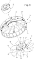
- the ventilation group 1 comprises a fan 2 having an axis R of rotation and a support shroud 3 of the fan 2.
- the fan 2 comprises an electric motor 4 and a fan 5 having axial flow, or simply an axial fan, actuated by the motor 2, rotatable about the axis R of rotation.
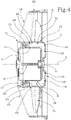
- the motor 4 preferably of the closed and sealed type, substantially of known type and described only regarding the parts necessary for understanding the present invention, comprises an external casing 6, a cap 7 for closing the casing and a shaft 8, coaxial with the axis R, to which the fan 5 is connected.
- the shaft 8 comprises an end portion 9 protruding from the casing 6 on the opposite side with respect to the cap 7 to which the fan 5 is connected, for example by interference fitting.
- the shroud 3 comprises a ring 10 for supporting the motor 4, to which the motor 4 is fixed in the substantially known way, for example, by means of screws in suitable protrusions extending from the ring 10.
- the motor 4 is inserted internally of the fixed ring 10 and is supported thereby.
- the ring 10 has a external annular wall 11 from which project, on the side opposite the motor, a plurality of arms or spokes 12 of substantially known type.
- the wall annular 11 advantageously projects axially up to the cap 7 on the opposite side to the fan 5.
- the wall 11 preferably, has radial dimensions equal to the radial dimensions of the hub 14.
- the shroud 3 comprises a tubular element 13 external of the ring 10 and to which the arms 12 are connected.
- the ventilation group 1 is installed in a generic application, which is not illustrated, by means of the element tubular 13 which in turn, by means of the arms 12 and the ring 10, supports the fan 2.
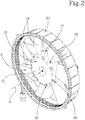
- the fan 5 comprises a cup-shaped hub 14 and a plurality of blades 15 extending from the hub 14 and preferably made in a single body with the hub by moulding using a plastic material.
- the motor 4 is housed at least partly internally of the hub 14.
- the hub 14 comprises an end wall 16 by means of which the fan 5 is connected to the shaft 8.
- the hub 14 comprises a lateral wall 17 extending from the end wall 16 and having a peripheral edge 18, substantially circular in shape, on the side opposite the end wall 16 along the axis R of rotation.
- the end wall 16 and the lateral wall 17 define a cup-shaped structure for the hub 14.
- the blades 15 extend preferably from the lateral wall 17 of the hub 14 towards the outside thereof, externally of the cup-shaped structure.
- the fan 5 comprises a plurality of fins 19, preferably made in a single body with the hub 14, internal of the cup-shaped structure for generating, in use, a descending flow of tangential air internally of the hub 14 for removing heat from the motor 4.
- the fins 19 are angularly equispaced internally of the hub 14 and are for example seven in number.
- Each fin 19 comprises a portion 20 projecting beyond the peripheral edge 18 of the lateral wall 17, externally of the cup-shaped structure, i.e. outside the hub 14.
- the end portions 20 protrude externally of the hub 14 along an axial direction, substantially parallel with the axis R of rotation of the fan 2.
- each appendage 19 has a first portion 21 extending from lateral wall 17 internally of the hub 14, preferably radially.
- the first portion 21 has main extension direction that is parallel to the axis R of rotation of the fan 5 and preferably extends along the entire axial dimension of the hub 14 towards the inside of the hub 14.
- the end portions 20 are preferably defined by an at least partial extension of the first portion 21 beyond the edge 18.
- each fin 19 comprises a second portion 22 extending from the end wall 16 towards the inside of the hub 14.
- Each second portion 22 is connected and extends into a corresponding first portion 21.
- Each second portion 22 preferably has a main extension direction that is substantially radial and extends towards the inside of the hub 14.
- the fins 19 are substantially L-shaped, with the second radial portion 22 and the first axial portion 21 located inside the hub 14 and the end portion 20 exiting therefrom.
- Each end portion 20 has an internal edge 23 facing internally of the hub 14, i.e., towards the electric motor 4, and an external edge 24 facing externally of the hub 14, i.e. towards the blades 15.
- the external edge 24 is at a radial distance from the axis R of rotation that is less than a radial distance of a radially inner surface of the lateral wall 17 from the axis R of rotation.
- each portion 20 is slimmed in a radial direction relative to the corresponding first portion 21 of the respective fin 19.
- the hub 14 has a plurality of through-holes 25 at a connecting zone 26 of the end wall 16 and the lateral wall 17.
- the connecting zone 26 preferably has a curved extension and the holes 25 preferably have rounded edges.
- annular wall 11 delimits, with the external surface of the electric motor 4, an annular channel 27.
- the end portions 20 of the fins 19 are preferably at least partly inserted internally of the channel 27.
- the portions 20 are slimmed as described in the foregoing so as to be inserted internally of the channel 27.
- the lateral wall 11 of the ring 10 preferably has a radial dimension substantially corresponding to the radial dimension of the hub 14 and in particular of the lateral wall 17 thereof. More precisely, a substantially cylindrical internal surface of the wall 11 has the same internal diameter as the lateral wall 17 of the hub 14.
- a component of the tangential flow for cooling the cap is determined by the portions 20 of the fins which extend outside the hub internally of the annular channel 27.
Landscapes
- Engineering & Computer Science (AREA)
- Mechanical Engineering (AREA)
- General Engineering & Computer Science (AREA)
- Physics & Mathematics (AREA)
- Thermal Sciences (AREA)
- Structures Of Non-Positive Displacement Pumps (AREA)
- Motor Or Generator Cooling System (AREA)
Claims (12)
- Axialgebläse aufweisend eine Drehachse (R) und umfassend
eine Nabe (14) umfassend eine Bodenwand (16) und eine Seitenwand (17), die sich von der Bodenwand (16) erstreckt und aufweisend eine Umfangskante (18) auf einer gegenüberliegenden Seite in Bezug auf die Bodenwand (16) entlang der Drehachse (R), wobei die Bodenwand (16) und die Seitenwand (17) eine becherförmige Struktur der Nabe (14) bilden, wobei das Gebläse eine Vielzahl an Schaufeln (15) umfasst, die sich von der Seitenwand (17) außerhalb der becherförmigen Struktur erstrecken;
mindestens eine Rippe (19) innerhalb der becherförmigen Struktur zum Erzeugen, in Verwendung, eines tangentialen Luftstroms innerhalb der Nabe (14), wobei die Rippe (19) einen Endabschnitt (20) umfasst, der über die Umfangskante (18) außerhalb der Nabe (14) herausragt, der eine Innenkante (23), die nach innen der Nabe (14) zugewandt ist und eine Außenkante (24) aufweist, die nach außen der Nabe (14) zugewandt ist, wobei das Gebläse dadurch gekennzeichnet ist, dass die Außenkante (24) in einem radialen Abstand von der Drehachse (R) positioniert ist, der kleiner als ein radialer Abstand einer radial innenliegenden Innenfläche der Seitenwand (17) von der Drehachse (R) ist. - Gebläse nach Anspruch 1, wobei die Rippe (19) einen ersten Abschnitt (21) aufweist, der sich von der Seitenwand (17) zur Innenseite der Nabe (14) erstreckt, wobei der Endabschnitt (20) durch eine zumindest teilweise Erstreckung des ersten Abschnitts (21) definiert ist.
- Gebläse nach Anspruch 2, wobei der erste Abschnitt (21) parallel zur Drehachse (R) verläuft.
- Gebläse nach einem der Ansprüche 1 bis 3, wobei die Rippe (19) einen zweiten Abschnitt (22) umfasst, der sich von der Bodenwand (16) zur Innenseite der Nabe (14) erstreckt.
- Gebläse nach Anspruch 4, wobei sich der zweite Abschnitt (22) radial von der Drehachse (R) erstreckt.
- Gebläse nach einem der vorhergehenden Ansprüche, wobei sich der Endabschnitt (20) hauptsächlich parallel zur Drehachse (R) erstreckt.
- Gebläse nach einem der vorhergehenden Ansprüche, wobei die Nabe (14) eine Vielzahl an Durchgangslöchern (25) in einer Zone (26) aufweist, die die Bodenwand (16) und die Seitenwand (17) verbindet.
- Gebläse nach einem der vorhergehenden Ansprüche, wobei die Nabe (14), die Schaufeln (15) und die Rippe (19) durch Formen in einem einzigen Teil hergestellt sind.
- Lüftungsgruppe mit
einem Gebläse (2) und einer Stützabdeckung (3) des Gebläses (2), wobei das Gebläse (2) einen Elektromotor (4) und einen vom Elektromotor betätigten Lüfter (5) umfasst,
wobei der Elektromotor (4) ein Gehäuse (6), eine Kappe (7) zum Verschließen des Gehäuses (6) und eine Welle (8) umfasst, mit der der Lüfter (5) verbunden ist, wobei die Abdeckung (3) einen Stützring (10) des Elektromotors (4) mit einer äußeren Ringwand (11) umfasst, wobei die Lüftungsgruppe dadurch gekennzeichnet ist, dass der Lüfter (5) von dem Typ nach einem der Ansprüche 1 bis 8 ist und der Elektromotor (1) zumindest teilweise innerhalb der Nabe (14) untergebracht ist. - Lüftungsgruppe nach Anspruch 9, wobei die äußere Ringwand (11) mit dem Elektromotor (4) einen Ringkanal (27) begrenzt, wobei der Endabschnitt (20) der Rippe (19) zumindest teilweise im Ringkanal (27) eingesetzt ist.
- Lüftungsgruppe nach Anspruch 9 oder 10, wobei die Welle (8) einen Endabschnitt (9) umfasst, der aus dem Gehäuse (6) auf der gegenüberliegenden Seite von der Kappe (7) herausragt, mit der die Nabe (14) des Lüfters (5) verbunden ist, wobei sich die äußere Ringwand (11) axial bis zur Kappe (7) auf der gegenüberliegenden Seite in Bezug auf den Lüfter (5) erstreckt.
- Lüftungsgruppe nach einem der Ansprüche 9 bis 11, wobei die äußere Ringwand eine radiale Abmessung (11) aufweist, die gleich der radialen Abmessung der Nabe (14) ist.
Applications Claiming Priority (2)
| Application Number | Priority Date | Filing Date | Title |
|---|---|---|---|
| ITUB20151741 | 2015-06-29 | ||
| PCT/IB2016/053893 WO2017002039A1 (en) | 2015-06-29 | 2016-06-29 | A fan and a ventilation group comprising the fan |
Publications (2)
| Publication Number | Publication Date |
|---|---|
| EP3314128A1 EP3314128A1 (de) | 2018-05-02 |
| EP3314128B1 true EP3314128B1 (de) | 2020-10-21 |
Family
ID=54011840
Family Applications (1)
| Application Number | Title | Priority Date | Filing Date |
|---|---|---|---|
| EP16745173.1A Active EP3314128B1 (de) | 2015-06-29 | 2016-06-29 | Gebläse und lüftungsgruppe mit diesem gebläse |
Country Status (7)
| Country | Link |
|---|---|
| US (1) | US20180187688A1 (de) |
| EP (1) | EP3314128B1 (de) |
| JP (1) | JP2018519471A (de) |
| KR (1) | KR102560506B1 (de) |
| CN (1) | CN107709791B (de) |
| BR (1) | BR112017028106A2 (de) |
| WO (1) | WO2017002039A1 (de) |
Families Citing this family (2)
| Publication number | Priority date | Publication date | Assignee | Title |
|---|---|---|---|---|
| US12258971B1 (en) | 2023-09-13 | 2025-03-25 | Honda Motor Co., Ltd. | Fan assembly |
| WO2026024968A1 (en) * | 2024-07-24 | 2026-01-29 | Evapco, Inc. | Packaged fan |
Family Cites Families (10)
| Publication number | Priority date | Publication date | Assignee | Title |
|---|---|---|---|---|
| IT1308475B1 (it) * | 1999-05-07 | 2001-12-17 | Gate Spa | Motoventilatore, particolarmente per uno scambiatore di calore di unautoveicolo |
| DE10161367A1 (de) * | 2001-12-14 | 2003-07-03 | Conti Temic Microelectronic | Elektrische Antriebseinheit |
| ITBO20040047A1 (it) * | 2004-02-03 | 2004-05-03 | Spal Srl | Ventilatore assiale |
| EP1621773B1 (de) * | 2004-07-30 | 2013-04-17 | Brose Fahrzeugteile GmbH & Co. KG, Würzburg | Kühlgebläse mit Elektromotor |
| DE502004010520D1 (de) * | 2004-07-30 | 2010-01-28 | Brose Fahrzeugteile | Elektromotor |
| TWI300284B (en) * | 2005-04-18 | 2008-08-21 | Delta Electronics Inc | Heat-dissipation structure of motor |
| TWI327457B (en) * | 2006-03-03 | 2010-07-11 | Delta Electronics Inc | Fan, motor and impeller thereof |
| DE102010001354A1 (de) * | 2009-08-26 | 2011-03-03 | Robert Bosch Gmbh | Gebläse |
| IT1404254B1 (it) * | 2011-01-25 | 2013-11-15 | Gate Srl | Ventola, particolarmente per un gruppo di ventilazione per uno scambiatore di calore di un autoveicolo |
| ITTO20120765A1 (it) * | 2012-09-05 | 2014-03-06 | Johnson Electric Asti S R L | Gruppo di ventilazione, particolarmente per uno scambiatore di calore di un veicolo |
-
2016
- 2016-06-29 CN CN201680037080.5A patent/CN107709791B/zh active Active
- 2016-06-29 US US15/739,511 patent/US20180187688A1/en not_active Abandoned
- 2016-06-29 EP EP16745173.1A patent/EP3314128B1/de active Active
- 2016-06-29 KR KR1020177037620A patent/KR102560506B1/ko active Active
- 2016-06-29 BR BR112017028106A patent/BR112017028106A2/pt not_active Application Discontinuation
- 2016-06-29 JP JP2017568287A patent/JP2018519471A/ja active Pending
- 2016-06-29 WO PCT/IB2016/053893 patent/WO2017002039A1/en not_active Ceased
Non-Patent Citations (1)
| Title |
|---|
| None * |
Also Published As
| Publication number | Publication date |
|---|---|
| KR102560506B1 (ko) | 2023-07-28 |
| BR112017028106A2 (pt) | 2018-08-28 |
| CN107709791B (zh) | 2020-09-15 |
| EP3314128A1 (de) | 2018-05-02 |
| CN107709791A (zh) | 2018-02-16 |
| WO2017002039A1 (en) | 2017-01-05 |
| US20180187688A1 (en) | 2018-07-05 |
| JP2018519471A (ja) | 2018-07-19 |
| KR20180019615A (ko) | 2018-02-26 |
Similar Documents
| Publication | Publication Date | Title |
|---|---|---|
| US20150263591A1 (en) | Active cooling of a motor having an integrated cooling channel | |
| CN103671250B (zh) | 风扇装置 | |
| CN105612355B (zh) | 转子轮毂装置和电风扇 | |
| JP6253593B2 (ja) | ファンモジュール | |
| US9800118B2 (en) | Self-cooled motor | |
| US10468938B2 (en) | Electric motor, and air blast device and air-conditioning and/or heating ventilation system provided with such a motor | |
| KR101714477B1 (ko) | 무인항공로봇의 동력원용 유선형 블레이드를 가지는 외전형 모터 | |
| JP6340819B2 (ja) | 送風装置 | |
| US20150295470A1 (en) | Self-cooled motor | |
| US20080247874A1 (en) | Dual flow fan heat sink application | |
| EP3314128B1 (de) | Gebläse und lüftungsgruppe mit diesem gebläse | |
| US9790947B2 (en) | Fan assembly | |
| CN113193688A (zh) | 一种自带外冷却结构的ip55工业吊扇电机 | |
| CN210669788U (zh) | 一种风冷轴向磁场盘式电机 | |
| WO2016203778A1 (ja) | 回転電機 | |
| JP2009191627A (ja) | 電動ファン装置 | |
| KR20120111257A (ko) | 냉각팬 및 그것을 구비하는 모터 회전자 어셈블리 | |
| JP2017096232A (ja) | 電動式送風機 | |
| JP6764823B2 (ja) | 回転電機 | |
| CN209743197U (zh) | 斜流式通风机 | |
| US20180372110A1 (en) | Axial flow fan | |
| CN108880101A (zh) | 一种永磁调速器的散热结构 | |
| KR101973567B1 (ko) | 팬쉬라우드 조립체 | |
| JP7560631B2 (ja) | モータ | |
| KR102573356B1 (ko) | 팬 슈라우드 조립체 |
Legal Events
| Date | Code | Title | Description |
|---|---|---|---|
| STAA | Information on the status of an ep patent application or granted ep patent |
Free format text: STATUS: THE INTERNATIONAL PUBLICATION HAS BEEN MADE |
|
| PUAI | Public reference made under article 153(3) epc to a published international application that has entered the european phase |
Free format text: ORIGINAL CODE: 0009012 |
|
| STAA | Information on the status of an ep patent application or granted ep patent |
Free format text: STATUS: REQUEST FOR EXAMINATION WAS MADE |
|
| 17P | Request for examination filed |
Effective date: 20180126 |
|
| AK | Designated contracting states |
Kind code of ref document: A1 Designated state(s): AL AT BE BG CH CY CZ DE DK EE ES FI FR GB GR HR HU IE IS IT LI LT LU LV MC MK MT NL NO PL PT RO RS SE SI SK SM TR |
|
| AX | Request for extension of the european patent |
Extension state: BA ME |
|
| DAV | Request for validation of the european patent (deleted) | ||
| DAX | Request for extension of the european patent (deleted) | ||
| GRAP | Despatch of communication of intention to grant a patent |
Free format text: ORIGINAL CODE: EPIDOSNIGR1 |
|
| STAA | Information on the status of an ep patent application or granted ep patent |
Free format text: STATUS: GRANT OF PATENT IS INTENDED |
|
| INTG | Intention to grant announced |
Effective date: 20200302 |
|
| GRAJ | Information related to disapproval of communication of intention to grant by the applicant or resumption of examination proceedings by the epo deleted |
Free format text: ORIGINAL CODE: EPIDOSDIGR1 |
|
| STAA | Information on the status of an ep patent application or granted ep patent |
Free format text: STATUS: REQUEST FOR EXAMINATION WAS MADE |
|
| GRAS | Grant fee paid |
Free format text: ORIGINAL CODE: EPIDOSNIGR3 |
|
| STAA | Information on the status of an ep patent application or granted ep patent |
Free format text: STATUS: GRANT OF PATENT IS INTENDED |
|
| GRAP | Despatch of communication of intention to grant a patent |
Free format text: ORIGINAL CODE: EPIDOSNIGR1 |
|
| INTC | Intention to grant announced (deleted) | ||
| INTG | Intention to grant announced |
Effective date: 20200720 |
|
| GRAA | (expected) grant |
Free format text: ORIGINAL CODE: 0009210 |
|
| STAA | Information on the status of an ep patent application or granted ep patent |
Free format text: STATUS: THE PATENT HAS BEEN GRANTED |
|
| AK | Designated contracting states |
Kind code of ref document: B1 Designated state(s): AL AT BE BG CH CY CZ DE DK EE ES FI FR GB GR HR HU IE IS IT LI LT LU LV MC MK MT NL NO PL PT RO RS SE SI SK SM TR |
|
| REG | Reference to a national code |
Ref country code: GB Ref legal event code: FG4D |
|
| REG | Reference to a national code |
Ref country code: CH Ref legal event code: EP |
|
| REG | Reference to a national code |
Ref country code: IE Ref legal event code: FG4D |
|
| REG | Reference to a national code |
Ref country code: DE Ref legal event code: R096 Ref document number: 602016046241 Country of ref document: DE |
|
| REG | Reference to a national code |
Ref country code: AT Ref legal event code: REF Ref document number: 1326108 Country of ref document: AT Kind code of ref document: T Effective date: 20201115 |
|
| REG | Reference to a national code |
Ref country code: AT Ref legal event code: MK05 Ref document number: 1326108 Country of ref document: AT Kind code of ref document: T Effective date: 20201021 |
|
| REG | Reference to a national code |
Ref country code: NL Ref legal event code: MP Effective date: 20201021 |
|
| PG25 | Lapsed in a contracting state [announced via postgrant information from national office to epo] |
Ref country code: FI Free format text: LAPSE BECAUSE OF FAILURE TO SUBMIT A TRANSLATION OF THE DESCRIPTION OR TO PAY THE FEE WITHIN THE PRESCRIBED TIME-LIMIT Effective date: 20201021 Ref country code: GR Free format text: LAPSE BECAUSE OF FAILURE TO SUBMIT A TRANSLATION OF THE DESCRIPTION OR TO PAY THE FEE WITHIN THE PRESCRIBED TIME-LIMIT Effective date: 20210122 Ref country code: PT Free format text: LAPSE BECAUSE OF FAILURE TO SUBMIT A TRANSLATION OF THE DESCRIPTION OR TO PAY THE FEE WITHIN THE PRESCRIBED TIME-LIMIT Effective date: 20210222 Ref country code: RS Free format text: LAPSE BECAUSE OF FAILURE TO SUBMIT A TRANSLATION OF THE DESCRIPTION OR TO PAY THE FEE WITHIN THE PRESCRIBED TIME-LIMIT Effective date: 20201021 Ref country code: NO Free format text: LAPSE BECAUSE OF FAILURE TO SUBMIT A TRANSLATION OF THE DESCRIPTION OR TO PAY THE FEE WITHIN THE PRESCRIBED TIME-LIMIT Effective date: 20210121 |
|
| REG | Reference to a national code |
Ref country code: LT Ref legal event code: MG4D |
|
| PG25 | Lapsed in a contracting state [announced via postgrant information from national office to epo] |
Ref country code: SE Free format text: LAPSE BECAUSE OF FAILURE TO SUBMIT A TRANSLATION OF THE DESCRIPTION OR TO PAY THE FEE WITHIN THE PRESCRIBED TIME-LIMIT Effective date: 20201021 Ref country code: BG Free format text: LAPSE BECAUSE OF FAILURE TO SUBMIT A TRANSLATION OF THE DESCRIPTION OR TO PAY THE FEE WITHIN THE PRESCRIBED TIME-LIMIT Effective date: 20210121 Ref country code: PL Free format text: LAPSE BECAUSE OF FAILURE TO SUBMIT A TRANSLATION OF THE DESCRIPTION OR TO PAY THE FEE WITHIN THE PRESCRIBED TIME-LIMIT Effective date: 20201021 Ref country code: IS Free format text: LAPSE BECAUSE OF FAILURE TO SUBMIT A TRANSLATION OF THE DESCRIPTION OR TO PAY THE FEE WITHIN THE PRESCRIBED TIME-LIMIT Effective date: 20210221 Ref country code: LV Free format text: LAPSE BECAUSE OF FAILURE TO SUBMIT A TRANSLATION OF THE DESCRIPTION OR TO PAY THE FEE WITHIN THE PRESCRIBED TIME-LIMIT Effective date: 20201021 Ref country code: ES Free format text: LAPSE BECAUSE OF FAILURE TO SUBMIT A TRANSLATION OF THE DESCRIPTION OR TO PAY THE FEE WITHIN THE PRESCRIBED TIME-LIMIT Effective date: 20201021 Ref country code: AT Free format text: LAPSE BECAUSE OF FAILURE TO SUBMIT A TRANSLATION OF THE DESCRIPTION OR TO PAY THE FEE WITHIN THE PRESCRIBED TIME-LIMIT Effective date: 20201021 |
|
| PG25 | Lapsed in a contracting state [announced via postgrant information from national office to epo] |
Ref country code: NL Free format text: LAPSE BECAUSE OF FAILURE TO SUBMIT A TRANSLATION OF THE DESCRIPTION OR TO PAY THE FEE WITHIN THE PRESCRIBED TIME-LIMIT Effective date: 20201021 Ref country code: HR Free format text: LAPSE BECAUSE OF FAILURE TO SUBMIT A TRANSLATION OF THE DESCRIPTION OR TO PAY THE FEE WITHIN THE PRESCRIBED TIME-LIMIT Effective date: 20201021 |
|
| REG | Reference to a national code |
Ref country code: DE Ref legal event code: R097 Ref document number: 602016046241 Country of ref document: DE |
|
| PG25 | Lapsed in a contracting state [announced via postgrant information from national office to epo] |
Ref country code: SK Free format text: LAPSE BECAUSE OF FAILURE TO SUBMIT A TRANSLATION OF THE DESCRIPTION OR TO PAY THE FEE WITHIN THE PRESCRIBED TIME-LIMIT Effective date: 20201021 Ref country code: RO Free format text: LAPSE BECAUSE OF FAILURE TO SUBMIT A TRANSLATION OF THE DESCRIPTION OR TO PAY THE FEE WITHIN THE PRESCRIBED TIME-LIMIT Effective date: 20201021 Ref country code: LT Free format text: LAPSE BECAUSE OF FAILURE TO SUBMIT A TRANSLATION OF THE DESCRIPTION OR TO PAY THE FEE WITHIN THE PRESCRIBED TIME-LIMIT Effective date: 20201021 Ref country code: SM Free format text: LAPSE BECAUSE OF FAILURE TO SUBMIT A TRANSLATION OF THE DESCRIPTION OR TO PAY THE FEE WITHIN THE PRESCRIBED TIME-LIMIT Effective date: 20201021 Ref country code: CZ Free format text: LAPSE BECAUSE OF FAILURE TO SUBMIT A TRANSLATION OF THE DESCRIPTION OR TO PAY THE FEE WITHIN THE PRESCRIBED TIME-LIMIT Effective date: 20201021 Ref country code: EE Free format text: LAPSE BECAUSE OF FAILURE TO SUBMIT A TRANSLATION OF THE DESCRIPTION OR TO PAY THE FEE WITHIN THE PRESCRIBED TIME-LIMIT Effective date: 20201021 |
|
| PLBE | No opposition filed within time limit |
Free format text: ORIGINAL CODE: 0009261 |
|
| STAA | Information on the status of an ep patent application or granted ep patent |
Free format text: STATUS: NO OPPOSITION FILED WITHIN TIME LIMIT |
|
| PG25 | Lapsed in a contracting state [announced via postgrant information from national office to epo] |
Ref country code: DK Free format text: LAPSE BECAUSE OF FAILURE TO SUBMIT A TRANSLATION OF THE DESCRIPTION OR TO PAY THE FEE WITHIN THE PRESCRIBED TIME-LIMIT Effective date: 20201021 |
|
| 26N | No opposition filed |
Effective date: 20210722 |
|
| PG25 | Lapsed in a contracting state [announced via postgrant information from national office to epo] |
Ref country code: AL Free format text: LAPSE BECAUSE OF FAILURE TO SUBMIT A TRANSLATION OF THE DESCRIPTION OR TO PAY THE FEE WITHIN THE PRESCRIBED TIME-LIMIT Effective date: 20201021 |
|
| PG25 | Lapsed in a contracting state [announced via postgrant information from national office to epo] |
Ref country code: SI Free format text: LAPSE BECAUSE OF FAILURE TO SUBMIT A TRANSLATION OF THE DESCRIPTION OR TO PAY THE FEE WITHIN THE PRESCRIBED TIME-LIMIT Effective date: 20201021 |
|
| PG25 | Lapsed in a contracting state [announced via postgrant information from national office to epo] |
Ref country code: MC Free format text: LAPSE BECAUSE OF FAILURE TO SUBMIT A TRANSLATION OF THE DESCRIPTION OR TO PAY THE FEE WITHIN THE PRESCRIBED TIME-LIMIT Effective date: 20201021 |
|
| REG | Reference to a national code |
Ref country code: CH Ref legal event code: PL |
|
| REG | Reference to a national code |
Ref country code: BE Ref legal event code: MM Effective date: 20210630 |
|
| PG25 | Lapsed in a contracting state [announced via postgrant information from national office to epo] |
Ref country code: LU Free format text: LAPSE BECAUSE OF NON-PAYMENT OF DUE FEES Effective date: 20210629 |
|
| PG25 | Lapsed in a contracting state [announced via postgrant information from national office to epo] |
Ref country code: LI Free format text: LAPSE BECAUSE OF NON-PAYMENT OF DUE FEES Effective date: 20210630 Ref country code: IE Free format text: LAPSE BECAUSE OF NON-PAYMENT OF DUE FEES Effective date: 20210629 Ref country code: CH Free format text: LAPSE BECAUSE OF NON-PAYMENT OF DUE FEES Effective date: 20210630 |
|
| PG25 | Lapsed in a contracting state [announced via postgrant information from national office to epo] |
Ref country code: IS Free format text: LAPSE BECAUSE OF FAILURE TO SUBMIT A TRANSLATION OF THE DESCRIPTION OR TO PAY THE FEE WITHIN THE PRESCRIBED TIME-LIMIT Effective date: 20210221 |
|
| PG25 | Lapsed in a contracting state [announced via postgrant information from national office to epo] |
Ref country code: BE Free format text: LAPSE BECAUSE OF NON-PAYMENT OF DUE FEES Effective date: 20210630 |
|
| PG25 | Lapsed in a contracting state [announced via postgrant information from national office to epo] |
Ref country code: CY Free format text: LAPSE BECAUSE OF FAILURE TO SUBMIT A TRANSLATION OF THE DESCRIPTION OR TO PAY THE FEE WITHIN THE PRESCRIBED TIME-LIMIT Effective date: 20201021 |
|
| P01 | Opt-out of the competence of the unified patent court (upc) registered |
Effective date: 20230526 |
|
| PG25 | Lapsed in a contracting state [announced via postgrant information from national office to epo] |
Ref country code: HU Free format text: LAPSE BECAUSE OF FAILURE TO SUBMIT A TRANSLATION OF THE DESCRIPTION OR TO PAY THE FEE WITHIN THE PRESCRIBED TIME-LIMIT; INVALID AB INITIO Effective date: 20160629 |
|
| PG25 | Lapsed in a contracting state [announced via postgrant information from national office to epo] |
Ref country code: MK Free format text: LAPSE BECAUSE OF FAILURE TO SUBMIT A TRANSLATION OF THE DESCRIPTION OR TO PAY THE FEE WITHIN THE PRESCRIBED TIME-LIMIT Effective date: 20201021 |
|
| PG25 | Lapsed in a contracting state [announced via postgrant information from national office to epo] |
Ref country code: TR Free format text: LAPSE BECAUSE OF FAILURE TO SUBMIT A TRANSLATION OF THE DESCRIPTION OR TO PAY THE FEE WITHIN THE PRESCRIBED TIME-LIMIT Effective date: 20201021 |
|
| PG25 | Lapsed in a contracting state [announced via postgrant information from national office to epo] |
Ref country code: MT Free format text: LAPSE BECAUSE OF FAILURE TO SUBMIT A TRANSLATION OF THE DESCRIPTION OR TO PAY THE FEE WITHIN THE PRESCRIBED TIME-LIMIT Effective date: 20201021 |
|
| PGFP | Annual fee paid to national office [announced via postgrant information from national office to epo] |
Ref country code: DE Payment date: 20250626 Year of fee payment: 10 |
|
| PGFP | Annual fee paid to national office [announced via postgrant information from national office to epo] |
Ref country code: GB Payment date: 20250618 Year of fee payment: 10 |
|
| PGFP | Annual fee paid to national office [announced via postgrant information from national office to epo] |
Ref country code: FR Payment date: 20250624 Year of fee payment: 10 |
|
| PGFP | Annual fee paid to national office [announced via postgrant information from national office to epo] |
Ref country code: IT Payment date: 20250612 Year of fee payment: 10 |