EP3314145B1 - Frequenzabhängige dämpfventilanordnung - Google Patents
Frequenzabhängige dämpfventilanordnung Download PDFInfo
- Publication number
- EP3314145B1 EP3314145B1 EP16726824.2A EP16726824A EP3314145B1 EP 3314145 B1 EP3314145 B1 EP 3314145B1 EP 16726824 A EP16726824 A EP 16726824A EP 3314145 B1 EP3314145 B1 EP 3314145B1
- Authority
- EP
- European Patent Office
- Prior art keywords
- control
- piston
- damping
- arrangement
- valve arrangement
- Prior art date
- Legal status (The legal status is an assumption and is not a legal conclusion. Google has not performed a legal analysis and makes no representation as to the accuracy of the status listed.)
- Active
Links
Images


Classifications
-
- F—MECHANICAL ENGINEERING; LIGHTING; HEATING; WEAPONS; BLASTING
- F16—ENGINEERING ELEMENTS AND UNITS; GENERAL MEASURES FOR PRODUCING AND MAINTAINING EFFECTIVE FUNCTIONING OF MACHINES OR INSTALLATIONS; THERMAL INSULATION IN GENERAL
- F16F—SPRINGS; SHOCK-ABSORBERS; MEANS FOR DAMPING VIBRATION
- F16F9/00—Springs, vibration-dampers, shock-absorbers, or similarly-constructed movement-dampers using a fluid or the equivalent as damping medium
- F16F9/32—Details
- F16F9/34—Special valve constructions; Shape or construction of throttling passages
- F16F9/348—Throttling passages in the form of annular discs or other plate-like elements which may or may not have a spring action, operating in opposite directions or singly, e.g. annular discs positioned on top of the valve or piston body
- F16F9/3485—Throttling passages in the form of annular discs or other plate-like elements which may or may not have a spring action, operating in opposite directions or singly, e.g. annular discs positioned on top of the valve or piston body characterised by features of supporting elements intended to guide or limit the movement of the annular discs
-
- F—MECHANICAL ENGINEERING; LIGHTING; HEATING; WEAPONS; BLASTING
- F16—ENGINEERING ELEMENTS AND UNITS; GENERAL MEASURES FOR PRODUCING AND MAINTAINING EFFECTIVE FUNCTIONING OF MACHINES OR INSTALLATIONS; THERMAL INSULATION IN GENERAL
- F16F—SPRINGS; SHOCK-ABSORBERS; MEANS FOR DAMPING VIBRATION
- F16F9/00—Springs, vibration-dampers, shock-absorbers, or similarly-constructed movement-dampers using a fluid or the equivalent as damping medium
- F16F9/32—Details
- F16F9/34—Special valve constructions; Shape or construction of throttling passages
- F16F9/348—Throttling passages in the form of annular discs or other plate-like elements which may or may not have a spring action, operating in opposite directions or singly, e.g. annular discs positioned on top of the valve or piston body
- F16F9/3488—Throttling passages in the form of annular discs or other plate-like elements which may or may not have a spring action, operating in opposite directions or singly, e.g. annular discs positioned on top of the valve or piston body characterised by features intended to affect valve bias or pre-stress
-
- F—MECHANICAL ENGINEERING; LIGHTING; HEATING; WEAPONS; BLASTING
- F16—ENGINEERING ELEMENTS AND UNITS; GENERAL MEASURES FOR PRODUCING AND MAINTAINING EFFECTIVE FUNCTIONING OF MACHINES OR INSTALLATIONS; THERMAL INSULATION IN GENERAL
- F16F—SPRINGS; SHOCK-ABSORBERS; MEANS FOR DAMPING VIBRATION
- F16F9/00—Springs, vibration-dampers, shock-absorbers, or similarly-constructed movement-dampers using a fluid or the equivalent as damping medium
- F16F9/32—Details
- F16F9/50—Special means providing automatic damping adjustment, i.e. self-adjustment of damping by particular sliding movements of a valve element, other than flexions or displacement of valve discs; Special means providing self-adjustment of spring characteristics
- F16F9/512—Means responsive to load action, i.e. static load on the damper or dynamic fluid pressure changes in the damper, e.g. due to changes in velocity
-
- F—MECHANICAL ENGINEERING; LIGHTING; HEATING; WEAPONS; BLASTING
- F16—ENGINEERING ELEMENTS AND UNITS; GENERAL MEASURES FOR PRODUCING AND MAINTAINING EFFECTIVE FUNCTIONING OF MACHINES OR INSTALLATIONS; THERMAL INSULATION IN GENERAL
- F16F—SPRINGS; SHOCK-ABSORBERS; MEANS FOR DAMPING VIBRATION
- F16F9/00—Springs, vibration-dampers, shock-absorbers, or similarly-constructed movement-dampers using a fluid or the equivalent as damping medium
- F16F9/32—Details
- F16F9/50—Special means providing automatic damping adjustment, i.e. self-adjustment of damping by particular sliding movements of a valve element, other than flexions or displacement of valve discs; Special means providing self-adjustment of spring characteristics
- F16F9/512—Means responsive to load action, i.e. static load on the damper or dynamic fluid pressure changes in the damper, e.g. due to changes in velocity
- F16F9/5126—Piston, or piston-like valve elements
-
- F—MECHANICAL ENGINEERING; LIGHTING; HEATING; WEAPONS; BLASTING
- F16—ENGINEERING ELEMENTS AND UNITS; GENERAL MEASURES FOR PRODUCING AND MAINTAINING EFFECTIVE FUNCTIONING OF MACHINES OR INSTALLATIONS; THERMAL INSULATION IN GENERAL
- F16K—VALVES; TAPS; COCKS; ACTUATING-FLOATS; DEVICES FOR VENTING OR AERATING
- F16K15/00—Check valves
- F16K15/18—Check valves with actuating mechanism; Combined check valves and actuated valves
-
- F—MECHANICAL ENGINEERING; LIGHTING; HEATING; WEAPONS; BLASTING
- F16—ENGINEERING ELEMENTS AND UNITS; GENERAL MEASURES FOR PRODUCING AND MAINTAINING EFFECTIVE FUNCTIONING OF MACHINES OR INSTALLATIONS; THERMAL INSULATION IN GENERAL
- F16F—SPRINGS; SHOCK-ABSORBERS; MEANS FOR DAMPING VIBRATION
- F16F2228/00—Functional characteristics, e.g. variability, frequency-dependence
- F16F2228/06—Stiffness
- F16F2228/066—Variable stiffness
-
- F—MECHANICAL ENGINEERING; LIGHTING; HEATING; WEAPONS; BLASTING
- F16—ENGINEERING ELEMENTS AND UNITS; GENERAL MEASURES FOR PRODUCING AND MAINTAINING EFFECTIVE FUNCTIONING OF MACHINES OR INSTALLATIONS; THERMAL INSULATION IN GENERAL
- F16F—SPRINGS; SHOCK-ABSORBERS; MEANS FOR DAMPING VIBRATION
- F16F2230/00—Purpose; Design features
- F16F2230/18—Control arrangements
Definitions
- the invention relates to a Dämpfventilan extract with a frequency-dependent Dämpfkraftkennline, according to claim 1.
- the object of a vibration damper in a motor vehicle is to dampen the vibrations excited by the uneven road surface.
- a compromise must always be found between driving safety and driving comfort.
- a vibration damper, the Dämpfventilan Aunt is tuned hard and has a high Dämpfkraftkennline is optimal for a high driving safety. If a high level of comfort is to be met, then the damping valve arrangement should be as soft as possible. In a vibration damper with a conventional, not electronically adjustable by means of an actuator damping valve arrangement, this compromise can be found only with great difficulty.
- Dämpfventilan strips with a frequency-dependent Dämpfkraftkennline are known from the prior art, which are equipped with an additional electronic and / or mechanical control and switch on or off depending on a compression and / or rebound frequency of the vibration damper an additional Dämpfventilan nie.
- Exemplary of this can be the DE 44 41 047 C1 .
- Solutions are also known, one on the piston rod, coaxial with the damper piston mounted control arrangement comprising a control pot, and arranged in the control cup axially displaceable control piston.
- the control piston axially delimits an enclosed in the control pot control chamber which is connected via an inlet connection with the Dämpfventilan eleven.
- a spring element is arranged, which axially introduces a spring force in the control piston on the one hand and in the damping valve on the other hand. If the control chamber is filled with the damping fluid, the control piston shifts in the direction of damping valve and increased via the spring element, the contact pressure of the valve discs of the damping valve, which increases the damping force.
- the object of this invention is therefore to provide a simply constructed and inexpensive Dämpfventilan extract which has a frequency-dependent Dämpfkraftkennline and allows a simple defined influencing the hard Dämpfkraftkennline during operation.
- the damping valve arrangement has a connecting channel, which connects the first working chamber to the second working chamber, wherein the connecting channel is arranged such that it is at least partially closed by the control piston during an axial displacement of the control piston in the direction of the damping piston and during an axial displacement of the control piston is opened again in the direction of the bottom of the pot.
- the Fig. 1 shows an example embodiment of a Dämpfventilan extract according to claim 1.
- the Fig. 1 shows a piston rod 4, which has a piston rod pin 5.
- the piston rod pin 5 is a reduced diameter portion of the piston rod 4.
- the entire damping valve assembly 1 is threaded on the piston rod pin 5 and is between a portion of the piston rod 4 adjacent to the piston rod pin 5 which has a larger diameter than the piston rod pin 5 , and a fastening means 23, which in the Fig. 1 is shown as a piston rod nut, axially braced.
- the damping valve arrangement 1 comprises a damping piston 2, which is arranged inside a cylinder 31 filled with a damping fluid and fixed axially on a piston rod 4.
- the damping piston 2 is equipped with a piston seal 17, which radially seals them relative to the cylinder 31.
- the fixed to the piston rod 4 damper piston 2 is disposed axially displaceable within the cylinder 31 together with the piston rod 4 and divides the cylinder interior into a first piston rod side working chamber 32 and a second, remote from the piston rod 4 working space 33rd
- the damping piston 2 is equipped with one check valve in each flow direction of the damping fluid.
- the non-return valves each comprise at least one flow channel 16 which is embodied in the damping piston 2 and which is covered by at least one valve disk 15.
- the flow channels 16 may be covered by a plurality of valve disks 15 stacked one above the other - so-called valve disk packs.
- the number, size and design of the individual valve discs; 15 in a valve disc package define the contact pressure, as well as the damping characteristic, and the damping behavior of a vibration damper.
- control arrangement 3 mounted coaxially with the damping piston 2, wherein the control arrangement 3 comprises a thin-walled control pot 8 and a control piston 8 axially displaceable control piston 9.
- the control pot is formed from sheet metal.
- the control piston 9 may be made of a metal, a ceramic material as well as of a suitable plastic, with or without fiber reinforcement by cold forming, hot forming, casting, injection molding, turning or sintering.
- the control pot 8 has a cylindrical pot wall 29 and a disk-shaped pot bottom 30 arranged at an end of the control pot 8 facing away from the steam piston 2.
- control piston 9 bounded on the check valve side facing axially enclosed in the control chamber 8 control chamber 11, so that an axial displacement of the control piston 9 within the control pot 8, the volume of the control chamber 11 defined changes.
- the damping valve arrangement 1 furthermore has an inlet connection 36, which connects the first working space 32 with the control space 11.
- the inlet connection 36 may comprise at least one flow passage 13 connecting the bypass 6 to the first working space 32.
- damping valve arrangement 1 has a drain connection 37, which connects the control chamber 11 with the second working space 33.
- the embodiments shown in the figures provide that between the damping piston 2 and the bottom of the pot 30 of the control arrangement 3, a stop element 18, and a tubular guide bushing 21 are arranged.
- the spring assembly 24 comprises four spring washers 10, which are combined into two pairs of spring washers, and an outer support member and an inner support member, wherein it arrives in the illustrated spring assembly 24 on the position of the spring washer in the spring assembly 24 and the number of spring washers 10 rather plays a minor role.
- the one, the control piston 9 facing spring washer pair is supported axially with the outer edge region of the control piston 9.
- the second spring washer pair is arranged coaxially, wherein the inner edge region of the two spring washer pairs are supported axially on the inner support member.
- the second, the valve disc 15 facing spring washer pair is supported in the outer edge region of the outer support member, which faces on the opposite side to the valve disc 15 and applies to this in the operating state.
- the spring assembly 24 thus acts on the valve disc 15 axially in the direction of the flow channel 16 and the control piston 9 in the direction of the pot bottom 30 with a defined spring force.
- the control piston 9 surrounds the guide bushing 21 in the circumferential direction and slides axially on the outer surface of the guide bush 21, during a change in volume of the control chamber 11.
- a stop element 18 is clamped between the guide bushing 21 and the damping piston 4 and has a larger outer diameter than the guide bush 21 ,
- the stop element 18 serves as an axial stop for the control piston 9, which limits the axial movement of the control piston 9 in the direction of the damping piston 4 and influences the hard damping force characteristic.
- the stop element 18 assumes the function of a guide for the spring assembly 24, wherein the spring assembly 24 surrounds the stop element 18 in the circumferential direction.
- the damping valve arrangement has a connecting channel 41, which opens into the bypass 6 and connects the first working space 32 with the second working space 33.
- a connecting channel 41 which opens into the bypass 6 and connects the first working space 32 with the second working space 33.
- a flow connection 39 on the piston rod 4, a flow connection 39, on the guide bushing 21, a recess 40 and on the control piston 4, an opening 43 is executed. These are arranged such that they at least partially overlap each other, so that finally the connecting channel 41 has been formed.
- the damping fluid is conveyed via the inlet connection 36 from the working space 32 into the control chamber 11 and partly via the connecting channel 41 into the working space 33.
- the control piston 9 is displaced in the direction of the damping piston 2 due to the filling with the damping fluid control chamber 11 and thereby biases the axially projecting on the valve disc 15 of the check valve spring assembly 24 before. As a result, the damping force of the check valve is increased.
- the control piston 9 which moves in the direction of the damper piston 2 closes more and more the connecting duct 41, whereby the hard damping force characteristic curve increases in a defined manner.
- the control chamber 11 is not or only slightly filled, so that the spring assembly 24 is not further biased and the damping force remains at a defined low level.
- the integral of the Dofferenz of Dämpffluid réelle on the valve disc 15 to Dämpffluidyak in the control chamber 11 over time despite the throttle resistance of the inlet connection 36 large enough to supply the control chamber 11 so much Dämpffluid that the control piston 9 biases the spring assembly 24 until the control piston 9 to a between the guide bush 21 and the valve discs 15 of the check valve arranged stop element 18 meets.
- the stop element 18 limits the axial movement of the control piston 9 in the direction of the damping piston 2, and thus limits the maximum bias of the spring assembly 24 and thus the highest Dämpfkraftkennline, as well as the connecting channel 41 here has taken its smallest passage cross-section and thus the greatest flow resistance.
- Both the height of the bias acting on the valve disc 15, as well as the amount of the flowing through the connecting channel 41 Dämpffluides can be independently set arbitrarily within certain limits in the construction according to the invention.
- the bias is defined by the stiffness of the spring assembly 24 and the travel of the spool.
- the rigidity of the spring arrangement 24 will be carried out very softly.
- an additional spring not shown in the figures can be used, which exerts a force on the control piston 9, which presses it into the starting position.
- This spring could, for example, not be supported on the valve disk 15, but at least indirectly on the piston rod 4, for example on the stop element 18.
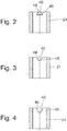
- FIGS. 2, 3 and 4 show a running on the guide bushing 21 recess 40, which at least partially obliquely to each other extending tangential edge portions 44; 45 has.
- the recess (40) formed on the guide bush 21 is at least partially parallel to one another extending tangential edge portions 44; 45, whereby a linear with the path of the control piston 9 change in the flow rate of the flowing through the connecting channel 41 Dämpffluides could be displayed.
- Fig. 5 Unlike the Fig. 1 includes in the Fig. 5 illustrated control assembly 3 a plurality of disc-shaped adjusting members 46 which additionally cover the connecting channel 41 at least partially.
- control assembly 3 realized as a preassemblable unit comprising a continuous inner sleeve 47 which penetrates all components of the control assembly 3 and holds together by a plastic deformation of the edge regions.
- the sleeve 47 takes over the task of the guide bushing 21 and the stopper member 18.
- the sleeve 47 includes one or more executed to form the connecting channel 41 transverse bores, which the recesses 40 in the Fig. 1 correspond functionally and which are closed when moving the control piston 9, as described above.
Landscapes
- Engineering & Computer Science (AREA)
- General Engineering & Computer Science (AREA)
- Mechanical Engineering (AREA)
- Physics & Mathematics (AREA)
- Fluid Mechanics (AREA)
- Fluid-Damping Devices (AREA)
Description
- Die Erfindung betrifft eine Dämpfventilanordnung mit einer frequenzabhängigen Dämpfkraftkennlinie, gemäß Patentanspruch 1.
- Die Aufgabe eines Schwingungsdämpfers in einem Kraftfahrzeug ist es die von dem unebenen Straßenbelag angeregten Schwingungen zu dämpfen. Dabei muss stets ein Kompromiss zwischen der Fahrsicherheit und dem Fahrkomfort gefunden werden. Ein Schwingungsdämpfer, dessen Dämpfventilanordnung hart abgestimmt ist und eine hohe Dämpfkraftkennlinie aufweist ist optimal für eine hohe Fahrsicherheit. Soll ein hoher Komfortanspruch erfüllt werden, so soll die Dämpfventilanordnung möglichst weich abgestimmt werden. Bei einem Schwingungsdämpfer mit einer konventionellen, nicht elektronisch mit Hilfe eines Aktuators verstellbaren Dämpfventilanordnung kann dieser Kompromiss nur sehr schwer gefunden werden.
- Aus dem Stand der Technik sind Dämpfventilanordnungen mit einer frequenzabhängigen Dämpfkraftkennlinie bekannt, welche mit einer zusätzlichen elektronischen und/oder Mechanischen Steuerung ausgerüstet sind und in Abhängigkeit von einer Einfederungs- und/oder Ausfederungsfrequenz des Schwingungsdämpfers eine zusätzliche Dämpfventilanordnung zuschalten oder abschalten.
- Beispielhaft dafür können die
DE 44 41 047 C1 ,US 2006 28 36 75 A oder dieUS 49 53 671 A genannt werden. - Es sind ebenfalls Lösungen bekannt, eine an der Kolbenstange, koaxial zu dem Dämpfkolben angebrachte Steueranordnung aufweisen, umfassend einen Steuertopf, sowie einen im Steuertopf angeordneten axial verschiebbaren Steuerkolben. Der Steuerkolben begrenzt axial einen im Steuertopf eingeschlossenen Steuerraum, welcher über eine Zulaufverbindung mit der Dämpfventilanordnung verbunden ist. Zwischen dem Steuerkolben und dem Dämpfventil ist ein Federelement angeordnet, welcher eine Federkraft in den Steuerkolben einerseits und in das Dämpfventil andererseits axial einleitet. Wird der Steuerraum mit dem Dämpffluid befüllt, so verschiebt sich der Steuerkolben in Richtung Dämpfventil und erhöht über das Federelement den Anpressdruck der Ventilscheiben des Dämpfventils, was die Dämpfkraft erhöht.
- Alle bekannten Dämpfventilanordnungen zeichnen sich jedoch durch eine hohe Komplexität aus, unter Anderem da diese eine hohe Abstimmungsgenauigkeit erfordern. Insbesondere ist es schwierig bei diesen Schwingungsdämpfern die weiche und die harte Dämpfkraftkennlinie ohne zusätzliche Steuerung einzustellen.
- Die Aufgabe dieser Erfindung ist daher, eine einfach aufgebaute und kostengünstige Dämpfventilanordnung anzugeben, welche eine frequenzabhängige Dämpfkraftkennlinie aufweist und eine einfache definierte Beeinflussung der harten Dämpfkraftkennlinie während des Betriebs ermöglicht.
- Diese Aufgabe wird durch eine Dämpfventilanordnung mit Merkmalen gemäß Patentanspruch 1 gelöst. Weitere vorteilhafte Ausführungen sind in den Figuren, sowie in den abhängigen Ansprüchen angegeben.
- Erfindungsgemäß weist die Dämpfventilanordnung einen Verbindungskanal auf, welcher den ersten Arbeitsraum mit dem zweiten Arbeitsraum verbindet, wobei der Verbindungskanal derart angeordnet ist, dass dieser bei einer axialen Verschiebung des Steuerkolben in Richtung des Dämpfkolbens von dem Steuerkolben zumindest teilweise verschlossen und bei einer axialen Verschiebung des Steuerkolbens in Richtung des Topfbodens wieder geöffnet wird.
- Dadurch wird die Durchflussmenge des Dämpffluides in den Steuerraum zusätzlich gesteuert und somit die harte Dämpfkraftkennlinie definiert beeinflusst.
- Anhand folgender Figurenbeschreibung soll die Erfindung näher erläutert werden. Es zeigen:
- Fig. 1:
- Eine Schnittdarstellung eines Ausführungsbeispiels einer Dämpfventilanordnung gemäß Patentanspruch 1;
- Fig. 2
- Eine Schnittdarstellung eines Ausführungsbeispiels einer Führungsbuchse;
- Fig. 3
- Eine Schnittdarstellung eines alternativen Ausführungsbeispiels einer Führungsbuchse;
- Fig. 4
- Eine Schnittdarstellung eines alternativen Ausführungsbeispiels einer Führungsbuchse;
- Fig. 5
- Eine Schnittdarstellung eines alternativen Ausführungsbeispiels einer Steueranordnung.
- Die
Fig. 1 zeigt eine beispielsweise Ausführungsvariante einer Dämpfventilanordnung gemäß Patentanspruch 1. - Die
Fig. 1 zeigt eine Kolbenstange 4, welche einen Kolbenstangenzapfen 5 aufweist. Bei dem Kolbenstangenzapfen 5 handelt es sich um einen im Durchmesser reduzierten Abschnitt der Kolbenstange 4. Die gesamte Dämpfventilanordnung 1 ist an dem Kolbenstangenzapfen 5 aufgefädelt und ist zwischen einem an dem Kolbenstangenzapfen 5 angrenzenden Abschnitt der Kolbenstange 4, welcher einen größeren Durchmesser aufweist als der Kolbenstangenzapfen 5, und einem Befestigungsmittel 23, welcher in derFig. 1 als eine Kolbenstangenmutter dargestellt ist, axial verspannt. - Wie in der
Fig. 1 dargestellt, umfasst die Dämpfventilanordnung 1 einen Dämpfkolben 2, welcher innerhalb eines mit einem Dämpffluid gefüllten Zylinders 31 angeordnet und an einer Kolbenstange 4 axial festgelegt ist. Der Dämpfkolben 2 ist mit einer Kolbendichtung 17 ausgestattet, welche diesen gegenüber dem Zylinder 31 radial abdichtet. Der an der Kolbenstange 4 festgelegte Dämpfkolben 2 ist innerhalb des Zylinders 31 gemeinsam mit der Kolbenstange 4 axial verschiebbar angeordnet und unterteilt den Zylinderinnenraum in einen ersten, kolbenstangenseitigen Arbeitsraum 32 und einen zweiten, von der Kolbenstange 4 abgewandten Arbeitsraum 33. - Der Dämpfkolben 2 ist mit jeweils einem Rückschlagventil in jeder Strömungsrichtung des Dämpffluides ausgestattet. Die Rückschlagventile umfassen dabei jeweils mindestens einen im Dämpfkolben 2 ausgeführten Strömungskanal 16, welcher mit mindestens einer Ventilscheibe 15 abgedeckt ist. Wie in den Figuren dargestellt, können die Strömungskanäle 16 durch mehrere übereinander gestapelte Ventilscheiben 15 - sogenannte Ventilscheibenpakete abgedeckt sein. Die Anzahl, die Größe und die Ausgestaltung der einzelnen Ventilscheiben; 15 in einem Ventilscheibenpaket definieren den Anpressdruck, sowie die Dämpfkennlinie, und das Dämpfverhalten eines Schwingungsdämpfers.
- An der Kolbenstange 4 ist eine Steueranordnung 3, koaxial zu dem Dämpfkolben 2 angebracht, wobei die Steueranordnung 3 einen dünnwandigen Steuertopf 8 und einen im Steuertopf 8 axial verschiebbaren Steuerkolben 9 umfasst. Der Steuertopf ist aus Blech ausgeformt. Der Steuerkolben 9 kann aus einem Metall, einem Keramikmaterial sowie auch aus einem geeigneten Kunststoff, mit oder auch ohne Faserverstärkung durch Kaltumformen, Warmumformen, Gießen, Spritzgießen, Drehen oder auch Sintern ausgeführt sein. Der Steuertopf 8 weist eine zylinderförmige Topfwand 29 und einen scheibenförmigen, an einem von dem Dämpfkolben 2 abgewandten Ende des Steuertopfes 8 angeordneten Topfboden 30 auf.
- Der im Steuertopf 8 angeordnete Steuerkolben 9 begrenzt auf der dem Rückschlagventil zugewandten Seite axial einen im Steuertopf 8 eingeschlossenen Steuerraum 11, sodass eine axiale Verschiebung des Steuerkolbens 9 innerhalb des Steuertopfes 8 das Volumen des Steuerraums 11 definiert verändert.
- Die Dämpfventilanordnung 1 weist des Weiteren eine Zulaufverbindung 36 auf, welche den ersten Arbeitsraum 32 mit dem Steuerraum 11 verbindet. Diese umfasst in der in
Fig. 1 abgebildeten Ausführungsvariante einen an der Kolbenstange 4 ausgeführten Bypass 6, sowie mindestens eine den Bypass 6 mit dem Steuerraum 11 verbindende Zulaufdrossel 20. Darüber hinaus kann die Zulaufverbindung 36 mindestens eine den Bypass 6 mit dem ersten Arbeitsraum 32 verbindende Strömungsausnehmung 13 umfassen. - Des Weiteren weist die Dämpfventilanordnung 1 eine Ablaufverbindung 37 auf, welche den Steuerraum 11 mit dem zweiten Arbeitsraum 33 verbindet.
- Die in den Figuren abgebildeten Ausführungsvarianten sehen vor, dass zwischen dem Dämpfkolben 2 und dem Topfboden 30 der Steueranordnung 3 ein Anschlagelement 18, sowie eine rohrförmige Führungsbuchse 21 angeordnet sind.
- Zwischen dem Steuerkolben 9 und dem Rückschlagventil ist eine Federanordnung 24 in Form mehrerer Federscheiben 10 angeordnet. Gemäß der in
Fig. 1 dargestellten Ausführungsvariante umfasst die Federanordnung 24 vier Federscheiben 10, welche in zwei Federscheibenpaare zusammengefasst sind, sowie ein äußeres Stützbauteil und ein inneres Stützbauteil, wobei es bei der dargestellten Federanordnung 24 auf die Position der Federscheibe in der Federanordnung 24 ankommt und die Anzahl der Federscheiben 10 eher eine untergeordnete Rolle Spielt. Wie in derFig. 1 dargestellt, stützt sich das eine, dem Steuerkolben 9 zugewandte Federscheibenpaar mit dessen äußerem Randbereich an dem Steuerkolben 9 axial ab. Dazu beabstandet ist das zweite Federscheibenpaar koaxial angeordnet, wobei der Innere Randbereich der beiden Federscheibenpaare sich axial an dem inneren Stützbauteil abstützen. Das zweite, der Ventilscheibe 15 zugewandte Federscheibenpaar wird in dessen äußerem Randbereich von dem äußeren Stützbauteil gestützt, welches an der gegenüberliegenden Seite zu der Ventilscheibe 15 zugewandt ist und sich an diese im Betriebszustand anlegt. - Die Federanordnung 24 beaufschlagt somit die Ventilscheibe 15 axial in Richtung des Strömungskanals 16 und den Steuerkolben 9 in Richtung des Topfbodens 30 mit einer definierten Federkraft.
- Der Steuerkolben 9 umgreift die Führungsbuchse 21 in Umfangsrichtung und gleitet axial an der äußeren Oberfläche der Führungsbuchse 21, während einer Volumenveränderung des Steuerraums 11. Ein Anschlagelement 18 ist zwischen der Führungsbuchse 21 und dem Dämpfkolben 4 verspannt und weist einen größeren Außendurchmesser als die Führungsbuchse 21 auf. Das Anschlagelement 18 dient als axialer Anschlag für den Steuerkolben 9, welcher die axiale Bewegung des Steuerkolbens 9 in Richtung Dämpfkolben 4 begrenzt und die harte Dämpfkraftkennlinie beeinflusst. Darüber hinaus übernimmt das Anschlagelement 18 die Funktion einer Führung für die Federanordnung 24, wobei die Federanordnung 24 das Anschlagelement 18 in Umfangsrichtung umgreift.
- Des Weiteren weist die Dämpfventilanordnung einen Verbindungskanal 41 auf, welcher in dem Bypass 6 mündet und den ersten Arbeitsraum 32 mit dem zweiten Arbeitsraum 33 verbindet. Die in
Fig. 1 abgebildete Ausführungsvariante sieht vor, dass an der Kolbenstange 4 eine Strömungsverbindung 39, an der Führungsbuchse 21 eine Ausnehmung 40 und an dem Steuerkolben 4 ein Durchbruch 43 ausgeführt ist. Diese sind derart angeordnet, dass sie einander zumindest teilweise überlagern, sodass schließlich der Verbindungskanal 41 gebildet wurde. - Es sei an dieser Stelle angemerkt, dass die in
Fig. 1 dargestellte Ausführungsvariante nicht als die einzig mögliche zu sehen ist und den Schutzumfang keineswegs einschränken soll. - Im Folgenden soll die Funktionsweise näher erläutert werden.
- Bei einer Bewegung der Kolbenstange 4 und der daran festgelegten Dämpfventilanordnung 1 in Zugrichtung Z wird das Dämpffluid über die Zulaufverbindung 36 aus dem Arbeitsraum 32 in den Steuerraum 11 und teilweise über den Verbindungskanal 41 in den Arbeitsraum 33 befördert. Der Steuerkolben 9 wird aufgrund des sich mit dem Dämpffluid füllenden Steuerraumes 11 in Richtung Dämpfkolben 2 verschoben und spannt dabei die sich an der Ventilscheibe 15 des Rückschlagventils axial abstützende Federanordnung 24 weiter vor. Dadurch wird die Dämpfkraft des Rückschlagventils erhöht.
- Der sich in Richtung Dämpfkolben 2 bewegende Steuerkolben 9 verschließt immer mehr den Verbindungskanal 41, wodurch die harte Dämpfkraftkennlinie definiert ansteigt.
- Bei schnellen, kleineren Axialbewegungen des Dämpfkolbens 2 innerhalb des Zylinders 31 wird der Steuerraum 11 gar nicht oder nur geringfügig befüllt, so dass die Federanordnung 24 nicht weiter vorgespannt wird und die Dämpfkraft auf einem definiertem niedrigem Niveau bleibt. Bei größeren, langsameren Axialbewegungen des Dämpfkolbens 2 innerhalb des Zylinders 31 jedoch ist das Integral aus der Dofferenz von Dämpffluiddruck auf die Ventilscheibe 15 zu Dämpffluiddruck im Steuerraum 11 über die Zeit, trotz des Drosselwiderstandes der Zulaufverbindung 36 groß genug, um dem Steuerraum 11 so viel Dämpffluid zuzuführen, dass der Steuerkolben 9 die Federanordnung 24 vorspannt, bis der Steuerkolben 9 auf ein zwischen der Führungsbuchse 21 und den Ventilscheiben 15 des Rückschlagventils angeordnete Anschlagelement 18 trifft. Das Anschlagelement 18 begrenzt die axiale Bewegung des Steuerkolbens 9 in Richtung Dämpfkolben 2, und begrenzt damit die maximale Vorspannung der Federanordnung 24 und damit auch die höchste Dämpfkraftkennlinie, da auch der Verbindungskanal 41 hier seinen kleinsten Durchlassquerschnitt und damit den größten Strömungswiderstand eingenommen hat.
- Sowohl die Höhe der auf die Ventilscheibe 15 wirkenden Vorspannung, als auch die Menge des durch den Verbindungskanal 41 strömenden Dämpffluides lassen sich bei der erfindungsgemäßen Konstruktion unabhängig voneinander beliebig innerhalb gewisser Grenzen einstellen. Die Vorspannung ist durch die Steifigkeit der Federanordnung 24 und den Weg des Steuerkolbens definiert. Die Menge des durch den Verbindungskanal 41 strömenden Dämpffluides über die tangentiale Breite und die Anzahl der Verbindungskanäle 41. Soll sich Die Menge des Dämpffluides nichtlinear mit dem Weg des Steuerkolbens 9 verändern, so lässt sich dies leicht realisieren, in dem die tangentialen Randabschnitte der Verbindungskanäle nicht parallel zueinander verlaufen, wie es beispielsweise in den
Figuren 2, 3 und 4 dargestellt ist. - Soll die Verstellung der Menge des durch den Verbindungskanal 41 strömenden Dämpffluides dominant sein, so wird man die Steifigkeit der Federanordnung 24 sehr weich ausführen. Dann kann beispielsweise eine in den Figuren nicht dargestellte zusätzliche Feder verwendet werden, die eine Kraft auf den Steuerkolben 9 ausübt, welche diesen in die Ausgangsstellung drückt. Diese Feder könnte sich beispielsweise nicht an der Ventilscheibe 15, sondern zumindest mittelbar an der Kolbenstange 4 abstützen, beispielweise an dem Anschlagelement 18.
- Die
Figuren 2, 3 und 4 zeigen eine an der Führungsbuchse 21 ausgeführte Ausnehmung 40, welche zumindest teilweise schräg zueinander verlaufende tangentialen Randabschnitte 44; 45 aufweist. Es kann aber auch vorgesehen sein, dass die an der Führungsbuchse 21 ausgeführte Ausnehmung (40) zumindest teilweise parallel zueinander verlaufende tangentialen Randabschnitte 44; 45 aufweist, wodurch eine mit dem Weg des Steuerkolbens 9 lineare Veränderung der Durchflussmenge des durch den Verbindungskanal 41 strömenden Dämpffluides darstellbar wäre. - Im Unterschied zu der
Fig. 1 umfasst die in derFig. 5 dargestellte Steueranordnung 3 mehrere scheibenförmige Einstellbauteile 46, welche den Verbindungskanal 41 zusätzlich zumindest teilweise verdecken. - Darüber hinaus ist die in der
Fig. 5 dargestellte Steueranordnung 3 als eine vormontierbare Einheit realisiert, welche eine durchgehende innere Hülse 47 umfasst, welche alle Komponenten der Steueranordnung 3 durchdringt und durch eine plastische Verformung der Randbereiche zusammenhält. Darüber hinaus übernimmt die Hülse 47 die Aufgabe der Führungsbuchse 21 und des Anschlagelements 18. Die Hülse 47 umfasst eine oder mehrere zur Bildung des Verbindungskanals 41 ausgeführte Querbohrungen, welche den Ausnehmungen 40 in derFig. 1 funktionell entsprechen und welche beim Verschieben des Steuerkolbens 9, wie vorstehend beschrieben, verschlossen werden. -
- 1
- Dämpfventilanordnung
- 2
- Dämpfkolben
- 3
- Steueranordnung
- 4
- Kolbenstange
- 5
- Kolbenstangenzapfen
- 6
- Bypass
- 7
- Stützscheibe
- 8
- Steuertopf
- 9
- Steuerkolben
- 10
- Federscheibe
- 11
- Steuerraum
- 12
- Kippscheibe
- 13
- radiale Strömungsausnehmung
- 14
- Ventilscheibe
- 15
- Ventilscheibe
- 16
- Strömungskanal
- 17
- Kolbendichtung
- 18
- Anschlagelement
- 19
- Anschlag
- 20
- Zulaufdrossel
- 21
- Führungsbuchse
- 22
- Scheibe
- 23
- Befestigungsmittel
- 24
- Federanordnung
- 29
- Topfwand
- 30
- Topfboden
- 31
- Zylinder
- 32
- erster Arbeitsraum
- 33
- zweiter Arbeitsraum
- 34
- erste Drosselausnehmung
- 35
- zweite Drosselausnehmung
- 36
- Zulaufverbindung
- 37
- Ablaufverbindung
- 38
- Ablaufdrossel
- 39
- Strömungsverbindung
- 40
- Ausnehmung
- 41
- Verbindungskanal
- 42
- Ringraum
- 43
- Durchbruch
- 44
- Randabschnitt
- 45
- Randabschnitt
- 46
- Einstellbauteil
- 47
- Hülse
- 48
- äußeres Stützbauteil
- 49
- inneres Stützbauteil
- 50
- Querbohrung
- L
- Längsachse
- Z
- Zugrichtung
Claims (9)
- Dämpfventilanordnung (1) für einen Schwingungsdämpfer, umfassend:- einen innerhalb eines mit einem Dämpffluid zumindest teilweise gefüllten Zylinders (31) angeordneten, an einer Kolbenstange (4) axial festgelegten, axial verschieblichen Dämpfkolben (2) welcher mindestens einen im Dämpfkolben (2) ausgeführten, mit mindestens einer Ventilscheibe (15) abgedeckten Strömungskanal (16) aufweist und welcher den Zylinder (31) in einen ersten, kolbenstangenseitigen Arbeitsraum (32) und einen zweiten, von der Kolbenstange (4) abgewandten Arbeitsraum (33) unterteilt,- eine an der Kolbenstange (4), koaxial zu dem Dämpfkolben (2) angebrachte Steueranordnung (3), umfassend einen Steuertopf (8) mit einer zylinderförmigen Topfwand (29) und einem scheibenförmigen, an einem von dem Dämpfkolben (2) abgewandten Ende des Steuertopfes (8) angeordneten Topfboden (30), sowie einen im Steuertopf (8) angeordneten axial verschiebbaren Steuerkolben (9), welcher einen im Steuertopf (8) eingeschlossenen Steuerraum (11) axial begrenzt und wobei die Dämpfventilanordnung (1) eine Zulaufverbindung (36) aufweist, welche den ersten Arbeitsraum (32) mit dem Steuerraum (11) verbindet, und wobei zwischen dem Steuerkolben (8) und dem Dämpfkolben (2) mindestens eine Federanordnung (24) angeordnet ist, welche die Ventilscheibe (15) axial in Richtung des Strömungskanals (16) und den Steuerkolben (9) in Richtung des Topfbodens (30) mit einer definierten Federkraft beaufschlagt, dadurch gekennzeichnet, dass die Dämpfventilanordnung einen Verbindungskanal (41) aufweist, welcher den ersten Arbeitsraum (32) mit dem zweiten Arbeitsraum (33) verbindet, wobei der Verbindungskanal (41) derart angeordnet ist, dass dieser bei einer axialen Verschiebung des Steuerkolbens (9) in Richtung des Dämpfkolbens (2) von dem Steuerkolben (9) zumindest teilweise verschlossen und bei einer axialen Verschiebung des Steuerkolbens (9) in Richtung des Topfbodens (30) wieder geöffnet wird.
- Dämpfventilanordnung (1) für einen Schwingungsdämpfer nach Anspruch 1, dadurch gekennzeichnet, dass der Verbindungskanal (41) eine an der Kolbenstange (4) ausgeführte Strömungsverbindung (39) umfasst.
- Dämpfventilanordnung (1) für einen Schwingungsdämpfer nach zumindest einem der Ansprüche 1 oder 2, dadurch gekennzeichnet, dass zwischen dem Dämpfkolben (2) und dem Topfboden (30) der Steueranordnung (3) eine rohrförmige Führungsbuchse (21) angeordnet ist, wobei der Steuerkolben (9) die Führungsbuchse (21) in Umfangsrichtung umgreift und axial an einer äußeren Oberfläche der Führungsbuchse (21) gleitet, und dass der Verbindungskanal (41) eine an der Führungsbuchse (21) ausgeführte Ausnehmung (40) umfasst.
- Dämpfventilanordnung (1) für einen Schwingungsdämpfer nach Anspruch 1, dadurch gekennzeichnet, dass der Verbindungskanal (41) einen an dem Steuerkolben (4) ausgeführten Durchbruch (43) umfasst.
- Dämpfventilanordnung (1) für einen Schwingungsdämpfer nach Anspruch 3, dadurch gekennzeichnet, dass die an der Führungsbuchse (21) ausgeführte Ausnehmung (40) zumindest teilweise parallel zueinander verlaufende tangentialen Randabschnitte (44; 45) aufweist.
- Dämpfventilanordnung (1) für einen Schwingungsdämpfer nach Anspruch 3, dadurch gekennzeichnet, dass die an der Führungsbuchse (21) ausgeführte Ausnehmung (40) zumindest teilweise schräg zueinander verlaufende tangentialen Randabschnitte (44; 45) aufweist.
- Dämpfventilanordnung (1) für einen Schwingungsdämpfer nach Anspruch 1, dadurch gekennzeichnet, dass die Steueranordnung (3) mindestens ein Einstellbauteil (46) umfasst, welches den Verbindungskanal (41) zumindest teilweise und zumindest zeitweise verdeckt.
- Dämpfventilanordnung (1) für einen Schwingungsdämpfer nach Anspruch 1, dadurch gekennzeichnet, dass die Steueranordnung (3) eine durchgehende innere Hülse (47) umfasst, welche alle Komponenten der Steueranordnung (3) durchdringt und durch eine plastische Verformung der Randbereiche zusammenhält.
- Dämpfventilanordnung (1) für einen Schwingungsdämpfer nach Anspruch 8, dadurch gekennzeichnet, dass die Hülse (47) umfasst mindestens eine zur Bildung des Verbindungskanals (41) ausgeführte Querbohrung (50) aufweist, welche bei einer axialen Verschiebung des Steuerkolbens (9) in Richtung der Federanordnung (24) von dem Steuerkolben (9) zumindest teilweise verschlossen und bei einer axialen Verschiebung des Steuerkolbens (9) in Richtung des Topfbodens (30) wieder geöffnet wird.
Applications Claiming Priority (2)
| Application Number | Priority Date | Filing Date | Title |
|---|---|---|---|
| DE102015211891.6A DE102015211891B4 (de) | 2015-06-26 | 2015-06-26 | Frequenzabhängige Dämpfventilanordnung |
| PCT/EP2016/061522 WO2016206880A1 (de) | 2015-06-26 | 2016-05-23 | Frequenzabhängige dämpfventilanordnung |
Publications (2)
| Publication Number | Publication Date |
|---|---|
| EP3314145A1 EP3314145A1 (de) | 2018-05-02 |
| EP3314145B1 true EP3314145B1 (de) | 2019-06-26 |
Family
ID=56098219
Family Applications (1)
| Application Number | Title | Priority Date | Filing Date |
|---|---|---|---|
| EP16726824.2A Active EP3314145B1 (de) | 2015-06-26 | 2016-05-23 | Frequenzabhängige dämpfventilanordnung |
Country Status (7)
| Country | Link |
|---|---|
| US (1) | US10473180B2 (de) |
| EP (1) | EP3314145B1 (de) |
| JP (1) | JP6633658B2 (de) |
| KR (1) | KR102427599B1 (de) |
| CN (1) | CN107810345B (de) |
| DE (1) | DE102015211891B4 (de) |
| WO (1) | WO2016206880A1 (de) |
Families Citing this family (13)
| Publication number | Priority date | Publication date | Assignee | Title |
|---|---|---|---|---|
| DE102016217114B4 (de) | 2016-09-08 | 2025-01-02 | Zf Friedrichshafen Ag | Frequenzabhängige Dämpfventilanordnung |
| DE102017200375B4 (de) * | 2017-01-11 | 2020-10-01 | Zf Friedrichshafen Ag | Dämpfventilanordnung |
| DE102017010876B4 (de) * | 2017-11-24 | 2023-06-01 | Günther Zimmer | Zylinder-Kolben-Einheit mit lastabhängiger Drossel |
| US11255399B2 (en) * | 2018-03-14 | 2022-02-22 | Zf Friedrichshafen Ag | Damping valve for a vibration damper |
| US10663027B2 (en) * | 2018-03-23 | 2020-05-26 | Tenneco Automotive Operating Company Inc. | Damper with valve preload limiter |
| US10570983B2 (en) | 2018-03-23 | 2020-02-25 | Tenneco Automotive Operating Company Inc. | Damper with floating piston bleed channel |
| DE102018211516A1 (de) | 2018-07-11 | 2020-01-16 | Zf Friedrichshafen Ag | Frequenzselektive Dämpfeinrichtung |
| ES2772349B2 (es) * | 2019-01-04 | 2022-03-21 | Kyb Europe Gmbh Sucursal En Navarra | Amortiguador con regulacion de carga hidraulica en funcion de la velocidad y de la frecuencia simultaneamente |
| CN110173535B (zh) * | 2019-06-10 | 2024-04-05 | 伯科姆汽车零部件系统(苏州)有限公司 | 一种频率自感应阻尼调节减振器复原阀总成 |
| DE102020000264A1 (de) | 2020-01-17 | 2021-07-22 | Zf Friedrichshafen Ag | Frequenzselektive Dämpfeinrichtung |
| CN113819296B (zh) * | 2020-06-19 | 2025-01-28 | 佛山市顺德区美的洗涤电器制造有限公司 | 阻尼开关、旋塞阀和燃气具 |
| CN112161015B (zh) | 2020-10-28 | 2022-05-06 | 北京京西重工有限公司 | 液压阻尼器组件和用于液压阻尼器组件的附加活塞 |
| DE102023209800A1 (de) * | 2023-10-09 | 2025-04-10 | Zf Friedrichshafen Ag | Steueranordnung für eine frequenzabhängige Dämpfventilvorrichtung eines Schwingungsdämpfers sowie Verfahren zur Herstellung der Steueranordnung |
Family Cites Families (33)
| Publication number | Priority date | Publication date | Assignee | Title |
|---|---|---|---|---|
| JPS6273136U (de) * | 1985-10-25 | 1987-05-11 | ||
| JPH0443633Y2 (de) * | 1986-09-17 | 1992-10-15 | ||
| JPH0251637A (ja) * | 1988-08-12 | 1990-02-21 | Tokico Ltd | 減衰力調整式油圧緩衝器 |
| JP2694465B2 (ja) * | 1989-05-19 | 1997-12-24 | トキコ株式会社 | 油圧緩衝器 |
| JP2918293B2 (ja) * | 1990-05-28 | 1999-07-12 | 株式会社ユニシアジェックス | 減衰力可変型緩衝器 |
| US5823305A (en) | 1992-10-08 | 1998-10-20 | Ricor Racing & Development, L.P. | Flow sensitive, acceleration sensitive shock absorber |
| JPH08105485A (ja) * | 1994-10-05 | 1996-04-23 | Unisia Jecs Corp | 周波数感応型液圧緩衝器 |
| JPH08135714A (ja) * | 1994-11-14 | 1996-05-31 | Toyota Motor Corp | 液圧緩衝装置 |
| US5810127A (en) * | 1994-11-18 | 1998-09-22 | August Bilstein Gmbh & Co. Kg | Proportional valve |
| DE4441047C1 (de) | 1994-11-18 | 1996-01-18 | Bilstein August Gmbh Co Kg | Proportionalventil |
| DE10258815A1 (de) * | 2002-12-17 | 2004-07-15 | Zf Sachs Ag | Schwingungsdämpfer mit amplitudenabhängiger Dämpfkraft |
| CN100526674C (zh) * | 2004-05-25 | 2009-08-12 | 日产自动车株式会社 | 液压缓冲器 |
| US7958981B2 (en) | 2005-06-06 | 2011-06-14 | Kayaba Industry Co., Ltd. | Shock absorber |
| JP4761474B2 (ja) * | 2007-09-06 | 2011-08-31 | カヤバ工業株式会社 | 緩衝器のバルブ構造 |
| JP2009079710A (ja) * | 2007-09-26 | 2009-04-16 | Showa Corp | 油圧緩衝器の減衰力調整構造 |
| JP2009085245A (ja) * | 2007-09-27 | 2009-04-23 | Showa Corp | 油圧緩衝器の減衰力調整構造 |
| JP5078574B2 (ja) | 2007-11-28 | 2012-11-21 | 株式会社ショーワ | 油圧緩衝器の減衰力調整構造 |
| US8794403B2 (en) * | 2008-02-13 | 2014-08-05 | Kayaba Industry Co., Ltd. | Damping force generating mechanism for hydraulic shock absorber |
| JP2011033125A (ja) * | 2009-07-31 | 2011-02-17 | Hitachi Automotive Systems Ltd | 緩衝器 |
| NL2003571C2 (nl) * | 2009-09-29 | 2011-03-30 | Koni Bv | Instelbare demper. |
| JP2011094691A (ja) * | 2009-10-29 | 2011-05-12 | Hitachi Automotive Systems Ltd | 緩衝器 |
| JP5584110B2 (ja) * | 2010-12-28 | 2014-09-03 | 日立オートモティブシステムズ株式会社 | 減衰力調整式緩衝器 |
| KR101288612B1 (ko) * | 2011-07-21 | 2013-07-22 | 주식회사 만도 | 쇽업소버의 밸브 구조 |
| KR101351590B1 (ko) * | 2012-03-13 | 2014-01-16 | 주식회사 만도 | 주파수 유닛 밸브 |
| KR101450309B1 (ko) | 2013-08-08 | 2014-10-22 | 주식회사 만도 | 쇽업소버의 피스톤 밸브 어셈블리 |
| KR101876915B1 (ko) * | 2013-10-28 | 2018-08-09 | 주식회사 만도 | 쇽업소버의 피스톤 밸브 어셈블리 |
| KR101671967B1 (ko) * | 2014-03-28 | 2016-11-03 | 주식회사 만도 | 쇽업소버의 피스톤 어셈블리 |
| DE102014210705A1 (de) * | 2014-06-05 | 2015-12-17 | Zf Friedrichshafen Ag | Frequenzabhängige Dämpfventilanordnung |
| DE102014210704B4 (de) * | 2014-06-05 | 2016-11-24 | Zf Friedrichshafen Ag | Frequenzabhängige Dämpfventilanordnung |
| KR102370708B1 (ko) * | 2015-05-11 | 2022-03-07 | 주식회사 만도 | 감쇠력 가변식 쇽업소버 |
| DE102015220707B4 (de) * | 2015-10-23 | 2022-06-02 | Zf Friedrichshafen Ag | Steueranordnung für eine frequenzabhängige Dämpfventileinrichtung eines Schwingungsdämpfers, sowie Verfahren zur plastischen Verformung des Topfbodens der Steueranordnung. |
| DE102016217112B4 (de) * | 2016-09-08 | 2022-10-06 | Zf Friedrichshafen Ag | Frequenzabhängige Dämpfventilanordnung |
| DE102016217113A1 (de) * | 2016-09-08 | 2016-12-01 | Zf Friedrichshafen Ag | Frequenzabhängige Dämpfventilanordnung |
-
2015
- 2015-06-26 DE DE102015211891.6A patent/DE102015211891B4/de active Active
-
2016
- 2016-05-23 JP JP2017564701A patent/JP6633658B2/ja active Active
- 2016-05-23 US US15/736,082 patent/US10473180B2/en active Active
- 2016-05-23 EP EP16726824.2A patent/EP3314145B1/de active Active
- 2016-05-23 WO PCT/EP2016/061522 patent/WO2016206880A1/de not_active Ceased
- 2016-05-23 KR KR1020187002096A patent/KR102427599B1/ko active Active
- 2016-05-23 CN CN201680037754.1A patent/CN107810345B/zh active Active
Non-Patent Citations (1)
| Title |
|---|
| None * |
Also Published As
| Publication number | Publication date |
|---|---|
| US10473180B2 (en) | 2019-11-12 |
| EP3314145A1 (de) | 2018-05-02 |
| CN107810345B (zh) | 2019-12-20 |
| US20180180134A1 (en) | 2018-06-28 |
| KR102427599B1 (ko) | 2022-08-01 |
| DE102015211891A1 (de) | 2016-12-29 |
| KR20180021109A (ko) | 2018-02-28 |
| JP2018518644A (ja) | 2018-07-12 |
| WO2016206880A1 (de) | 2016-12-29 |
| CN107810345A (zh) | 2018-03-16 |
| DE102015211891B4 (de) | 2021-10-14 |
| JP6633658B2 (ja) | 2020-01-22 |
Similar Documents
| Publication | Publication Date | Title |
|---|---|---|
| DE102015211891B4 (de) | Frequenzabhängige Dämpfventilanordnung | |
| EP0484648B1 (de) | Anschlag mit einer Dämpfungseinrichtung | |
| DE102014210704B4 (de) | Frequenzabhängige Dämpfventilanordnung | |
| EP3084259B1 (de) | Regelbarer schwingungsdämpfer für kraftfahrzeuge | |
| EP2255103B1 (de) | Schwingungsdämpfer mit rucksackventil | |
| EP1767810B1 (de) | Dämpfventileinrichtung mit progressivem Dämpfkraftverlauf | |
| DE102018201297B4 (de) | Schwingungsdämpfer für ein Fahrzeug | |
| WO2015185279A1 (de) | Frequenzabhängige dämpfventilanordnung | |
| WO2015165910A2 (de) | Schwingungsdämpfer eines fahrzeug-rads | |
| DE10326482A1 (de) | Dämpfer | |
| DE102019117233A1 (de) | Druckrückführkolben mit Ringschulter | |
| WO2015185274A1 (de) | Frequenzabhängige dämpfventilanordnung | |
| DE112021003611T5 (de) | Stossdämpfer | |
| EP3224498A1 (de) | Hydrolager sowie kraftfahrzeug mit einem derartigen hydrolager | |
| EP2327903A2 (de) | Dämpfventileinrichtung mit einer mehrstufigen Dämpfkraftkennlinie | |
| WO2015197213A1 (de) | Hydrolager sowie kraftfahrzeug mit einem derartigen hydrolager | |
| EP1719921A2 (de) | Zwischen einen Geber- und einen Nehmerzylinder eines hydraulischen Kraftübertragungssystems schaltbare Ventilanordnung zur Schwingungsentkopplung | |
| DE102019108070A1 (de) | Schwingungsdämpfer und Fahrzeug | |
| WO2003008836A1 (de) | Gasfeder-dämpfer-einheit | |
| EP3158218A1 (de) | Hydrolager sowie kraftfahrzeug mit einem derartigen hydrolager | |
| DE19851678C2 (de) | Hydraulische Servolenkung | |
| DE3625627A1 (de) | Vorrichtung zur hydraulischen steuerung von hubventilen | |
| DE1580775C (de) | Dämpfungszwischenwand für hydraulische Stoßdämpfer oder hydropneumatisch Federn für Kraftfahrzeuge | |
| DE102019003604A1 (de) | Schaltbares Hydrolager |
Legal Events
| Date | Code | Title | Description |
|---|---|---|---|
| STAA | Information on the status of an ep patent application or granted ep patent |
Free format text: STATUS: THE INTERNATIONAL PUBLICATION HAS BEEN MADE |
|
| PUAI | Public reference made under article 153(3) epc to a published international application that has entered the european phase |
Free format text: ORIGINAL CODE: 0009012 |
|
| STAA | Information on the status of an ep patent application or granted ep patent |
Free format text: STATUS: REQUEST FOR EXAMINATION WAS MADE |
|
| 17P | Request for examination filed |
Effective date: 20171128 |
|
| AK | Designated contracting states |
Kind code of ref document: A1 Designated state(s): AL AT BE BG CH CY CZ DE DK EE ES FI FR GB GR HR HU IE IS IT LI LT LU LV MC MK MT NL NO PL PT RO RS SE SI SK SM TR |
|
| AX | Request for extension of the european patent |
Extension state: BA ME |
|
| DAV | Request for validation of the european patent (deleted) | ||
| DAX | Request for extension of the european patent (deleted) | ||
| GRAP | Despatch of communication of intention to grant a patent |
Free format text: ORIGINAL CODE: EPIDOSNIGR1 |
|
| STAA | Information on the status of an ep patent application or granted ep patent |
Free format text: STATUS: GRANT OF PATENT IS INTENDED |
|
| INTG | Intention to grant announced |
Effective date: 20190118 |
|
| GRAS | Grant fee paid |
Free format text: ORIGINAL CODE: EPIDOSNIGR3 |
|
| GRAA | (expected) grant |
Free format text: ORIGINAL CODE: 0009210 |
|
| STAA | Information on the status of an ep patent application or granted ep patent |
Free format text: STATUS: THE PATENT HAS BEEN GRANTED |
|
| AK | Designated contracting states |
Kind code of ref document: B1 Designated state(s): AL AT BE BG CH CY CZ DE DK EE ES FI FR GB GR HR HU IE IS IT LI LT LU LV MC MK MT NL NO PL PT RO RS SE SI SK SM TR |
|
| REG | Reference to a national code |
Ref country code: GB Ref legal event code: FG4D Free format text: NOT ENGLISH |
|
| REG | Reference to a national code |
Ref country code: CH Ref legal event code: EP |
|
| REG | Reference to a national code |
Ref country code: AT Ref legal event code: REF Ref document number: 1148649 Country of ref document: AT Kind code of ref document: T Effective date: 20190715 |
|
| REG | Reference to a national code |
Ref country code: DE Ref legal event code: R096 Ref document number: 502016005273 Country of ref document: DE |
|
| REG | Reference to a national code |
Ref country code: IE Ref legal event code: FG4D Free format text: LANGUAGE OF EP DOCUMENT: GERMAN |
|
| REG | Reference to a national code |
Ref country code: NL Ref legal event code: MP Effective date: 20190626 |
|
| PG25 | Lapsed in a contracting state [announced via postgrant information from national office to epo] |
Ref country code: HR Free format text: LAPSE BECAUSE OF FAILURE TO SUBMIT A TRANSLATION OF THE DESCRIPTION OR TO PAY THE FEE WITHIN THE PRESCRIBED TIME-LIMIT Effective date: 20190626 Ref country code: LT Free format text: LAPSE BECAUSE OF FAILURE TO SUBMIT A TRANSLATION OF THE DESCRIPTION OR TO PAY THE FEE WITHIN THE PRESCRIBED TIME-LIMIT Effective date: 20190626 Ref country code: SE Free format text: LAPSE BECAUSE OF FAILURE TO SUBMIT A TRANSLATION OF THE DESCRIPTION OR TO PAY THE FEE WITHIN THE PRESCRIBED TIME-LIMIT Effective date: 20190626 Ref country code: NO Free format text: LAPSE BECAUSE OF FAILURE TO SUBMIT A TRANSLATION OF THE DESCRIPTION OR TO PAY THE FEE WITHIN THE PRESCRIBED TIME-LIMIT Effective date: 20190926 Ref country code: AL Free format text: LAPSE BECAUSE OF FAILURE TO SUBMIT A TRANSLATION OF THE DESCRIPTION OR TO PAY THE FEE WITHIN THE PRESCRIBED TIME-LIMIT Effective date: 20190626 Ref country code: FI Free format text: LAPSE BECAUSE OF FAILURE TO SUBMIT A TRANSLATION OF THE DESCRIPTION OR TO PAY THE FEE WITHIN THE PRESCRIBED TIME-LIMIT Effective date: 20190626 |
|
| REG | Reference to a national code |
Ref country code: LT Ref legal event code: MG4D |
|
| PG25 | Lapsed in a contracting state [announced via postgrant information from national office to epo] |
Ref country code: BG Free format text: LAPSE BECAUSE OF FAILURE TO SUBMIT A TRANSLATION OF THE DESCRIPTION OR TO PAY THE FEE WITHIN THE PRESCRIBED TIME-LIMIT Effective date: 20190926 Ref country code: GR Free format text: LAPSE BECAUSE OF FAILURE TO SUBMIT A TRANSLATION OF THE DESCRIPTION OR TO PAY THE FEE WITHIN THE PRESCRIBED TIME-LIMIT Effective date: 20190927 Ref country code: RS Free format text: LAPSE BECAUSE OF FAILURE TO SUBMIT A TRANSLATION OF THE DESCRIPTION OR TO PAY THE FEE WITHIN THE PRESCRIBED TIME-LIMIT Effective date: 20190626 Ref country code: LV Free format text: LAPSE BECAUSE OF FAILURE TO SUBMIT A TRANSLATION OF THE DESCRIPTION OR TO PAY THE FEE WITHIN THE PRESCRIBED TIME-LIMIT Effective date: 20190626 |
|
| PG25 | Lapsed in a contracting state [announced via postgrant information from national office to epo] |
Ref country code: EE Free format text: LAPSE BECAUSE OF FAILURE TO SUBMIT A TRANSLATION OF THE DESCRIPTION OR TO PAY THE FEE WITHIN THE PRESCRIBED TIME-LIMIT Effective date: 20190626 Ref country code: SK Free format text: LAPSE BECAUSE OF FAILURE TO SUBMIT A TRANSLATION OF THE DESCRIPTION OR TO PAY THE FEE WITHIN THE PRESCRIBED TIME-LIMIT Effective date: 20190626 Ref country code: PT Free format text: LAPSE BECAUSE OF FAILURE TO SUBMIT A TRANSLATION OF THE DESCRIPTION OR TO PAY THE FEE WITHIN THE PRESCRIBED TIME-LIMIT Effective date: 20191028 Ref country code: CZ Free format text: LAPSE BECAUSE OF FAILURE TO SUBMIT A TRANSLATION OF THE DESCRIPTION OR TO PAY THE FEE WITHIN THE PRESCRIBED TIME-LIMIT Effective date: 20190626 Ref country code: NL Free format text: LAPSE BECAUSE OF FAILURE TO SUBMIT A TRANSLATION OF THE DESCRIPTION OR TO PAY THE FEE WITHIN THE PRESCRIBED TIME-LIMIT Effective date: 20190626 Ref country code: RO Free format text: LAPSE BECAUSE OF FAILURE TO SUBMIT A TRANSLATION OF THE DESCRIPTION OR TO PAY THE FEE WITHIN THE PRESCRIBED TIME-LIMIT Effective date: 20190626 |
|
| PG25 | Lapsed in a contracting state [announced via postgrant information from national office to epo] |
Ref country code: ES Free format text: LAPSE BECAUSE OF FAILURE TO SUBMIT A TRANSLATION OF THE DESCRIPTION OR TO PAY THE FEE WITHIN THE PRESCRIBED TIME-LIMIT Effective date: 20190626 Ref country code: SM Free format text: LAPSE BECAUSE OF FAILURE TO SUBMIT A TRANSLATION OF THE DESCRIPTION OR TO PAY THE FEE WITHIN THE PRESCRIBED TIME-LIMIT Effective date: 20190626 Ref country code: IT Free format text: LAPSE BECAUSE OF FAILURE TO SUBMIT A TRANSLATION OF THE DESCRIPTION OR TO PAY THE FEE WITHIN THE PRESCRIBED TIME-LIMIT Effective date: 20190626 Ref country code: IS Free format text: LAPSE BECAUSE OF FAILURE TO SUBMIT A TRANSLATION OF THE DESCRIPTION OR TO PAY THE FEE WITHIN THE PRESCRIBED TIME-LIMIT Effective date: 20191026 |
|
| PG25 | Lapsed in a contracting state [announced via postgrant information from national office to epo] |
Ref country code: TR Free format text: LAPSE BECAUSE OF FAILURE TO SUBMIT A TRANSLATION OF THE DESCRIPTION OR TO PAY THE FEE WITHIN THE PRESCRIBED TIME-LIMIT Effective date: 20190626 |
|
| PG25 | Lapsed in a contracting state [announced via postgrant information from national office to epo] |
Ref country code: DK Free format text: LAPSE BECAUSE OF FAILURE TO SUBMIT A TRANSLATION OF THE DESCRIPTION OR TO PAY THE FEE WITHIN THE PRESCRIBED TIME-LIMIT Effective date: 20190626 Ref country code: PL Free format text: LAPSE BECAUSE OF FAILURE TO SUBMIT A TRANSLATION OF THE DESCRIPTION OR TO PAY THE FEE WITHIN THE PRESCRIBED TIME-LIMIT Effective date: 20190626 |
|
| PG25 | Lapsed in a contracting state [announced via postgrant information from national office to epo] |
Ref country code: IS Free format text: LAPSE BECAUSE OF FAILURE TO SUBMIT A TRANSLATION OF THE DESCRIPTION OR TO PAY THE FEE WITHIN THE PRESCRIBED TIME-LIMIT Effective date: 20200224 |
|
| REG | Reference to a national code |
Ref country code: DE Ref legal event code: R097 Ref document number: 502016005273 Country of ref document: DE |
|
| PLBE | No opposition filed within time limit |
Free format text: ORIGINAL CODE: 0009261 |
|
| STAA | Information on the status of an ep patent application or granted ep patent |
Free format text: STATUS: NO OPPOSITION FILED WITHIN TIME LIMIT |
|
| PG2D | Information on lapse in contracting state deleted |
Ref country code: IS |
|
| 26N | No opposition filed |
Effective date: 20200603 |
|
| PG25 | Lapsed in a contracting state [announced via postgrant information from national office to epo] |
Ref country code: SI Free format text: LAPSE BECAUSE OF FAILURE TO SUBMIT A TRANSLATION OF THE DESCRIPTION OR TO PAY THE FEE WITHIN THE PRESCRIBED TIME-LIMIT Effective date: 20190626 |
|
| PG25 | Lapsed in a contracting state [announced via postgrant information from national office to epo] |
Ref country code: CH Free format text: LAPSE BECAUSE OF NON-PAYMENT OF DUE FEES Effective date: 20200531 Ref country code: LI Free format text: LAPSE BECAUSE OF NON-PAYMENT OF DUE FEES Effective date: 20200531 Ref country code: MC Free format text: LAPSE BECAUSE OF FAILURE TO SUBMIT A TRANSLATION OF THE DESCRIPTION OR TO PAY THE FEE WITHIN THE PRESCRIBED TIME-LIMIT Effective date: 20190626 |
|
| REG | Reference to a national code |
Ref country code: BE Ref legal event code: MM Effective date: 20200531 |
|
| GBPC | Gb: european patent ceased through non-payment of renewal fee |
Effective date: 20200523 |
|
| PG25 | Lapsed in a contracting state [announced via postgrant information from national office to epo] |
Ref country code: LU Free format text: LAPSE BECAUSE OF NON-PAYMENT OF DUE FEES Effective date: 20200523 |
|
| PG25 | Lapsed in a contracting state [announced via postgrant information from national office to epo] |
Ref country code: IE Free format text: LAPSE BECAUSE OF NON-PAYMENT OF DUE FEES Effective date: 20200523 Ref country code: GB Free format text: LAPSE BECAUSE OF NON-PAYMENT OF DUE FEES Effective date: 20200523 Ref country code: FR Free format text: LAPSE BECAUSE OF NON-PAYMENT OF DUE FEES Effective date: 20200531 |
|
| PG25 | Lapsed in a contracting state [announced via postgrant information from national office to epo] |
Ref country code: BE Free format text: LAPSE BECAUSE OF NON-PAYMENT OF DUE FEES Effective date: 20200531 |
|
| PG25 | Lapsed in a contracting state [announced via postgrant information from national office to epo] |
Ref country code: MT Free format text: LAPSE BECAUSE OF FAILURE TO SUBMIT A TRANSLATION OF THE DESCRIPTION OR TO PAY THE FEE WITHIN THE PRESCRIBED TIME-LIMIT Effective date: 20190626 Ref country code: CY Free format text: LAPSE BECAUSE OF FAILURE TO SUBMIT A TRANSLATION OF THE DESCRIPTION OR TO PAY THE FEE WITHIN THE PRESCRIBED TIME-LIMIT Effective date: 20190626 |
|
| PG25 | Lapsed in a contracting state [announced via postgrant information from national office to epo] |
Ref country code: MK Free format text: LAPSE BECAUSE OF FAILURE TO SUBMIT A TRANSLATION OF THE DESCRIPTION OR TO PAY THE FEE WITHIN THE PRESCRIBED TIME-LIMIT Effective date: 20190626 |
|
| REG | Reference to a national code |
Ref country code: AT Ref legal event code: MM01 Ref document number: 1148649 Country of ref document: AT Kind code of ref document: T Effective date: 20210523 |
|
| PG25 | Lapsed in a contracting state [announced via postgrant information from national office to epo] |
Ref country code: AT Free format text: LAPSE BECAUSE OF NON-PAYMENT OF DUE FEES Effective date: 20210523 |
|
| P01 | Opt-out of the competence of the unified patent court (upc) registered |
Effective date: 20230528 |
|
| PGFP | Annual fee paid to national office [announced via postgrant information from national office to epo] |
Ref country code: DE Payment date: 20250325 Year of fee payment: 10 |