EP3314203B1 - Élément adapteur pour le montage d'un dispositif rotatif dans la chambre de mesure d'un appareil de mesure de coordonnées - Google Patents
Élément adapteur pour le montage d'un dispositif rotatif dans la chambre de mesure d'un appareil de mesure de coordonnées Download PDFInfo
- Publication number
- EP3314203B1 EP3314203B1 EP16731897.1A EP16731897A EP3314203B1 EP 3314203 B1 EP3314203 B1 EP 3314203B1 EP 16731897 A EP16731897 A EP 16731897A EP 3314203 B1 EP3314203 B1 EP 3314203B1
- Authority
- EP
- European Patent Office
- Prior art keywords
- adapter element
- axis
- coordinate
- measuring
- rotation
- Prior art date
- Legal status (The legal status is an assumption and is not a legal conclusion. Google has not performed a legal analysis and makes no representation as to the accuracy of the status listed.)
- Active
Links
Images


Classifications
-
- G—PHYSICS
- G01—MEASURING; TESTING
- G01B—MEASURING LENGTH, THICKNESS OR SIMILAR LINEAR DIMENSIONS; MEASURING ANGLES; MEASURING AREAS; MEASURING IRREGULARITIES OF SURFACES OR CONTOURS
- G01B5/00—Measuring arrangements characterised by the use of mechanical techniques
- G01B5/004—Measuring arrangements characterised by the use of mechanical techniques for measuring coordinates of points
- G01B5/008—Measuring arrangements characterised by the use of mechanical techniques for measuring coordinates of points using coordinate measuring machines
-
- G—PHYSICS
- G01—MEASURING; TESTING
- G01B—MEASURING LENGTH, THICKNESS OR SIMILAR LINEAR DIMENSIONS; MEASURING ANGLES; MEASURING AREAS; MEASURING IRREGULARITIES OF SURFACES OR CONTOURS
- G01B11/00—Measuring arrangements characterised by the use of optical techniques
- G01B11/002—Measuring arrangements characterised by the use of optical techniques for measuring two or more coordinates
- G01B11/005—Measuring arrangements characterised by the use of optical techniques for measuring two or more coordinates coordinate measuring machines
-
- G—PHYSICS
- G01—MEASURING; TESTING
- G01B—MEASURING LENGTH, THICKNESS OR SIMILAR LINEAR DIMENSIONS; MEASURING ANGLES; MEASURING AREAS; MEASURING IRREGULARITIES OF SURFACES OR CONTOURS
- G01B5/00—Measuring arrangements characterised by the use of mechanical techniques
- G01B5/0002—Arrangements for supporting, fixing or guiding the measuring instrument or the object to be measured
- G01B5/0004—Supports
Definitions
- the present invention relates to an adapter element for mounting a rotating device in the measuring space of a coordinate measuring machine, an arrangement comprising this adapter element, a coordinate measuring machine, comprising the adapter element or the arrangement and a method for determining the position of a rotation axis in a coordinate measuring machine.
- Coordinate measuring machines are often equipped with a turntable.
- the use of a turntable has application advantages. If, for example, the shape of a workpiece is measured with a turntable, a CMM gantry can remain stationary. This results in accuracy advantages in the (shape) measurement, since the movement errors of the CMM are not included in the measurement. Often, accessibility issues are also a reason for using a turntable, e.g. with internal undercuts that can not be scanned with a side-projecting button, which is attached to a CMM portal.
- the workpiece coordinates recorded by a probe are generated in the CMM coordinate system.
- the workpiece is on the turntable. Since the dimensional dimensions of a workpiece must be specified in the workpiece coordinate system, the detected workpiece coordinates are transformed into the workpiece coordinate system. For the transformation, the exact position and orientation (pose) of the turntable axis in the CMM coordinate system must be known.
- the pose of the turntable axis is not constant over time because, for example, the zero point of the CMM is drifting due to temperature fluctuations or self-heating. This problem is called "zero point drift”.
- Another possible source of error is a change in the probe vector, eg also due to temperature fluctuations.
- each drift in the measuring direction
- diameters can usually be better determined by scanning with the CMM portal. Users usually have no understanding for this because the measuring time is extended accordingly or the measuring task can not be solved due to accessibility problems.
- a measuring tool comprising: Means for coupling the measuring tool to a machine; a selectively rotatable stylus mount having on a portion of a base an axial bore and a branched arm portion extending from the portion of the base; a shaft extending between stylus support and said means for coupling the measuring tool and the machine and arranged along a central axis; and a substantially linear stylus extending from the stylus holder at an angle of 45 ° relative to the central axis, wherein said stylus is selectably adjustable along said 45 ° angle and is settable to terminate on the central axis such that a contact point for contacting the workpiece concentrically falls on the central axis.
- the publication US 2014/331510 A1 describes a measuring method for determining a reference point on a table center of an obliquely rotating table of a wire electric discharge machine using a measuring device.
- the WO 2013/156074 discloses an adapter plate for mounting an object on a measuring stage of a coordinate measuring machine or on a clamping surface of a machine tool, wherein the adapter plate is adapted to that an object on a mounting side of the adapter plate with one or more bearing surfaces and is fastened with one or more fasteners, and wherein the adapter plate is further adapted to be tightened by one or more clamping devices on the measuring table of a coordinate measuring machine or on the clamping surface of a machine tool, wherein on the opposite side of the fastening side of the adapter plate one or more projections are provided, wherein the one or more projections provided thereto is / are to be supported with his / her / its adapter plate opposite end against the measuring table or against the clamping surface, wherein the one or more projections are arranged substantially in areas that the b Said bearing surface or the said bearing surfaces are opposite and said clamping means or the said clamping means is / are / to clamp the adapter plate in the direction of the measuring table or the
- the DE 10159442 shows a calibration for coordinate measuring machines, wherein balls are connected by means of spacers to one, two or three-dimensional Kalibrormormalien firmly, the centers of the balls form predetermined calibration values, which can be calculated from the circumferential measurements of the balls.
- the known methods have the disadvantage of a long measuring time, insufficient accuracy and a high setup effort or space requirement on the measuring table.
- Backstops are required for long, slim workpieces, e.g. with steering spindles or crankshafts.
- an anvil When an anvil is used, the workpiece is usually clamped between a precisely centered stationary tip on the turntable and an opposing contiguous tip on the anvil.
- the follower tip on the anvil must be aligned as exactly as possible over the fixed tip on the turntable. The problem now is that the alignment of the anvil tip does not remain constant over time, i.a. because the material area of the measuring table between counterholder and turntable e.g. can drift when the temperature changes.
- a counter-holder represents a relatively large interference contour. Counterholds are therefore often built up and dismantled by the users. As described above, the counterholder must be aligned very closely to the turntable. This requires a lot of time.
- the object of the invention is to solve one or more of the problems identified above.
- the adapter element for example an adapter plate, for mounting a rotating device
- an additional coupling means which serves for coupling the additional device.
- an additional device can be coupled to the adapter element and also removed from the adapter element again.
- the additional device is in particular selected from a measuring body, for example for calibration purposes, a sensor holder and / or an accessory device for a likewise attached to the adapter element rotating device.
- a rotating device which is attached to the adapter element or can be arranged via the adapter element in a measuring space of a coordinate measuring machine, for example, be attached to a measuring table of a coordinate measuring machine.
- a rotating device can be provided with an additional device for various purposes.
- one or more measuring bodies for example, the position of a rotation axis of the rotating device can be determined or checked.
- the measuring bodies serve in this case as a reference for determining or checking the position of the axis of rotation.
- a device for holding a workpiece on or on the rotating device can be coupled to the adapter element as an accessory device.
- a counterholder can be coupled next to a turntable.
- both a rotating device and an additional device can be fastened or coupled to the same adapter element.
- the adapter element By the adapter element, a constant position and / or orientation of the rotating device and auxiliary device is achieved relative to each other.
- the position and / or orientation relative to each other is kept constant or substantially constant. For example, it may be assumed that the position and / or orientation of one or more measuring bodies does not change relative to a rotational axis of a rotating device or the position and / or orientation of a counter-holder does not change relative to a rotation axis of the rotary device.
- the coupling means for coupling an additional device is preferably arranged adjacent to an attachment point for the rotary device on the adapter element. This means that an auxiliary device in the coupled state adjacent to a rotating device, in other words, next to a rotating device, is positioned on the adapter element. A distance between the additional device and rotating device is preferably kept as low as possible.
- a coupling means for an additional device is preferably arranged on a same side of the adapter element as a fastening means and / or a fastening region for fastening the rotary device to the adapter element.
- a rotating device attached to the adapter element and an accessory device coupled to the adapter element are preferably fastened or coupled on the same side of the adapter element. This side of the adapter element is also referred to as attachment side or coupling side.
- the adapter element may have a plurality of coupling means, wherein each of the coupling means, or with each of the coupling means, an auxiliary device can be coupled to each.
- Type, number and composition of additional equipment can be freely selected in any combination, which will be discussed below special combinations.
- first and second coupling means are numbered for purposes of the following description for purposes of distinction, for example, referred to as “first” coupling means, “second” coupling means, etc.
- first, second,”third,” etc. mean numbering otherwise identically marked objects in order to be able to clearly distinguish the objects from one another.
- the numbering of otherwise identical items can be changed without departing from the spirit of the invention.
- the numbering may also be omitted in an alternative formulation and replaced by another unambiguous reference, for example, to another disclosed subject matter.
- a third coupling means it is not necessarily required that a first and a second coupling means also be present have to.
- a first coupling means for coupling a first measuring body may be present, a second coupling means for coupling a second measuring body, a third coupling means for coupling a third measuring body and a fourth coupling means for coupling an accessory device for the rotating device.
- the measuring space is a space in the CMM that is accessible for the purpose of measuring coordinates, in particular a space in which objects can be detected by a measuring system of the CMM for the purpose of measuring coordinates, in particular tactile or optical.
- a coupling means is in particular adapted to cooperate with one or more further coupling means to establish a coupling.
- a coupling means is a connecting means and serves to establish a connection, such as a connection to a said additional device.
- the connection can be positive and / or non-positive.
- the coupling means may be designed or arranged such that a coupling of the auxiliary device in a reproducible position and / or orientation is made possible.
- an additional device can be decoupled and coupled again in the same position and / or orientation.
- the adapter element may be formed in one piece or in several parts.
- the adapter element may have a first part, on which a fastening means or fastening area for fastening a rotary device is provided, and a second part, on which a coupling means for coupling an additional device is provided.
- Other parts third, fourth, etc. may be provided, each having a coupling means for coupling another attachment (second attachment, third attachment, etc.).
- a first part of an adapter element which may be referred to as a base part, can be extended by coupling possibilities for coupling one or more additional devices.
- an interface is preferably provided between a first part of an adapter element and a second part of an adapter element.
- the interface can enable a reproducible coupling of the parts, so that a specific position and / or orientation, preferably a specific position, of both parts can be reproducibly produced relative to one another.
- coupling means may be provided on the first part and the second part of an adapter element.
- Such coupling means can be designed to produce a reproducible coupling of the parts. In an analogous manner, this may apply to a third part, a fourth part, etc. of an adapter element.
- An adapter element can be designed in particular plate-shaped or angular, in the form of an adapter plate or an adapter bracket.
- a rotating device has in particular a rotor and a stator.
- a stator is preferably attached to an adapter element of the arrangement according to the invention and a rotor is rotatable relative to the adapter element.
- the rotor may be designed as a turntable.
- a rotor with a turntable or a face plate can be coupled.
- a workpiece can be positioned on a turntable or faceplate.
- the axis of rotation of the rotating device is to be understood in the sense of this invention as a virtual axis of rotation.
- the axis of rotation is a non-representational axis of rotation about which parts of the rotating device, in particular a rotor and a stator, are rotatable relative to each other.
- An additional device is in particular a calibration device, a measuring device or measuring auxiliary device or a device for holding a workpiece.
- the additional device may in particular be selected from a measuring body, a sensor holder and / or an accessory device for the rotating device.
- the coupling means for coupling an attachment may cooperate with another coupling means provided on the attachment.
- the coupling means on the adapter element and on the additional device can be designed to engage in one another in such a way that a unique relative position and / or orientation of the additional device can be produced relative to the adapter element.
- the connection can be secured from auxiliary device to adapter element by one or more further connection means in order to prevent release of the additional device from the adapter element.
- the coupling means may be formed on or attached to the adapter element.
- a coupling means may be formed in one piece or formed from several parts. Several parts of a coupling means may be individually attached to the adapter element. The same applies to a coupling agent which is provided on an additional device.
- Cooperating coupling means that is, for example, a coupling means on the adapter element and a coupling means on an additional device, in particular each have shape features, wherein the shape features of the two coupling means are complementary to one another.
- Two cooperating coupling means or coupling means provided for the interaction may be designed to form a positive and / or non-positive connection.
- a coupling means of an adapter element and a coupling means of an additional device can cooperate with one or more further coupling means, which can be a further, separate part, for establishing a coupling between the adapter element and the auxiliary device.
- adapter element and auxiliary device may each have a hole as a coupling means and as another coupling means may be added a screw which is passed through one of the holes and is screwed into an internal thread in the other of the holes.
- the coupling means on the adapter element and a cooperating coupling element are formed on an additional device for a plug connection or form a plug connection.
- an additional device may have a shaft which forms a coupling means of the additional device and the adapter element may have a recess into which the shaft can be inserted. The principle can be exactly the opposite.
- a coupling means on the adapter element may have at least one elevation (also referred to as a projection) and / or at least one depression.
- a coupling means on the additional device can have at least one elevation and / or at least one depression. The terms increase and deepening may be relative to each other. Elevations and / or depressions on the adapter element and on the additional device are preferably shaped complementary to each other. Examples of this are a crown and a counter-crown, which are preferably shaped complementary to each other. Further examples are plug connection elements, wherein a plug connection element is provided on the adapter element and a complementary plug connection element is provided on the additional device. Yet another example of interconnect coupling means is a screw and an internally threaded recess.
- first fastening means for fastening the adapter element in the measuring space in particular on a measuring table, can be attached to or formed on the adapter element.
- second fastening means for fastening the Turning device on the adapter element may be attached or formed on the adapter element. These fasteners may cooperate with other fasteners to provide attachment.
- the first attachment means is not limited.
- the first fastening means can cooperate with further fastening means for fastening the adapter element in the measuring space.
- Exemplary first fastening means are a plurality of holes, which are preferably in their arrangement congruent to a hole pattern in a measuring table. In holes of a perforated grid on the measuring table preferably threaded bushings are arranged.
- the adapter element with a screw which penetrates a hole in the adapter element are screwed onto the measuring table, wherein the screw is screwed into said threaded bushing.
- the hole in the adapter element is the mentioned first attachment means and the screw and the threaded bushing are further attachment means.
- the second attachment means is not limited. Examples include holes that can serve to produce a screw.
- the second fastening means may cooperate with other fastening means for establishing a connection between the rotary device and the adapter element.
- a first fastening region is in particular a structural region on the adapter element, which is suitable or designed for producing a fastening.
- a first attachment area may, for example, form a point of attachment or point of attack for another attachment means.
- the first attachment region may be an edge region of the adapter element, on which a clamp or clamping claw, as shown in FIG WO 2013/156074 known, can be applied.
- An analogous disclosure may apply to a second mounting area for mounting the rotary device.
- the adapter element preferably has an upper side and a lower side.
- the underside is the side with which the adapter element can be fastened in a measuring space, in particular can be fastened to a measuring table.
- the top is the side on which a turning device can be arranged.
- a second fastening means and / or a second fastening area is preferably arranged on the aforementioned upper side.
- a coupling means for coupling an additional device is preferably further arranged.
- An attachment of the adapter element in the measuring space of the CMM can be done in various ways. Mention was already the attachment to a measuring table. Usable are other components that can be arranged in or outside the measuring space and over which the adapter element can be mounted in the measuring space. Another component may for example be attached to a measuring table or another part of the CMM. For example, the adapter element will be attached to a frame surrounding the measuring table.
- a measuring body may be a tactile detectable measuring body or be an optically detectable measuring body.
- a tactile detectable measuring body is also referred to as probing body.
- a measuring body has a measuring body reference point, which can be determined by measuring the measuring body, or whose coordinates can be determined. Relative to the measuring body reference point, the position or change in position of another object, another spatial point or a spatial axis, in particular a rotation axis, can be determined.
- a probing body is a body which can be probed with a measuring system of a tactile measuring coordinate measuring machine.
- a tactile measuring system is known per se.
- a tactile measuring system has in particular a button.
- the probe can have a feeler element, for example a feeler ball or a differently shaped feeler element.
- a probing is done in particular with the button, more particularly with a probe element of the probe, as commonly known from tactile CMMs.
- a probe body has in particular a detectable by probing reference point, also called probing reference point.
- probing reference point also called probing reference point.
- at least one coordinate or the position or positional change of the axis of rotation, relative to one or more reference points can be determined by probing one or more probing bodies.
- One or more coordinates of a probing reference point may be known.
- a probing reference point may be positioned on a straight line parallel to a coordinate axis (CMM main axis) passing through a rotation axis and the reference point.
- CMS main axis coordinate axis
- the type of the impact body is not particularly limited as long as on or in the Antast redesign a time and relative to the body invariable reference point can be defined, which can be detected or determined reproducibly with the measuring system of the CMM.
- an impact body is selected from a ring, a disk, a cylinder, a hollow cylinder, a ball, a gauge block, an inner cone, a self-centering probe, or a combination thereof.
- An example of a ring is a blank ring that has a very small roundness deviation but may have any diameter.
- the CMM's measuring system can be touched at several points and the center of the ring, the disk, the cylinder or the ball can be determined from this.
- probing by scanning gives a higher measuring speed when determining a reference point, such as the ring or ball center.
- a circular scan can be performed, preferably in a constant Z height. Scanning means continuous, uninterrupted probing of a contour with continuous (dynamic) acquisition of the measured value, resulting in a density sequence.
- a measuring body can have a base, shaft or a connecting piece, via which the measuring body can be coupled. Furthermore, the measuring body may comprise the above-mentioned coupling means, which are attached or formed, for example, on a shaft, socket or connecting piece.
- the shape and configuration of a measuring body can be known or determined, for example with a measuring system of the CMM, which measuring body is currently used.
- measuring bodies with different heights shafts can be used. Whose length may be previously known or may be identifiable.
- measuring bodies of different shapes can be used, such as different geometric shapes in the case of probing bodies.
- the form may be previously known or determined.
- An accessory device for the rotary device is preferably a device for holding a workpiece.
- a workpiece, which is positioned on the rotating device, in particular on a rotor of the rotating device, can by means of a device for Holding a workpiece are held on the rotating device.
- Exemplary such devices are a counterholder mentioned at the beginning or a top block.
- the adapter element it is possible to couple a device for holding a workpiece to the adapter element.
- the coupling can be done in a reproducible manner, in particular, the device in position and / or orientation relative to a rotary device which is coupled to the adapter element, can be arranged reproducibly.
- the adapter element has a first coupling means for coupling a first measuring body and a second coupling means for coupling a second measuring body. Due to the possibility of coupling two measuring bodies, an even simpler and more accurate determination of the position of the axis of rotation can take place. In particular, two coordinates of a rotation axis in a device coordinate system of a CMM can be determined.
- the first coupling means and the second coupling means on the adapter element can be arranged and connectable first and second measuring bodies can be formed so that a first measuring body reference point (the first measuring body) and a second measuring body reference point (the second measuring body) on two different Coordinates of a rotation axis are positionable, such as an X and a Y coordinate of a rotation axis.
- the adapter element is as follows: when a rotating device is attached to the adapter element with a rotation axis and when a first measuring body and a second measuring body are coupled to the adapter element, a first virtual line extending from the axis of rotation of a rotating device attached to the adapter element closes extends to a measuring body reference point of the first measuring body and is perpendicular to the axis of rotation, and a second virtual line extending from the axis of rotation to a measuring body reference point of the second measuring body and perpendicular to the axis of rotation, an angle of 90 ° or Essentially 90 °. This will be discussed with reference to the inventive arrangement.
- the adapter element in addition to the above-mentioned first coupling means for coupling a first measuring body and the above-mentioned second coupling means for coupling a second measuring body, also has a third coupling means for coupling a third measuring body.
- a third measuring body reference point can be determined which defines a plane with a first measuring body reference point of the first measuring body and a second measuring body reference point of the second measuring body.
- a change in the position of the plane can be determined and from this a tilting of the adapter element, a rotating device or a rotation axis mounted therein, for example in a device coordinate system of a CMM.
- the adapter element comprises a fourth coupling means for coupling an accessory device for the rotating device, in particular a device for holding a workpiece, in particular a counter-holder or a top bracket.
- an accessory device for the rotating device in particular a device for holding a workpiece, in particular a counter-holder or a top bracket.
- the adapter element is made of a temperature-invariant material or has one or more regions of a temperature-invariant material.
- temperature-invariant means that the expansion coefficient of the material is less than or equal to 2.0 ⁇ 10 -6 K -1 in the temperature range of 20 ° C to 90 ° C.
- An exemplary such material is an iron-nickel alloy of 64% iron and 36% nickel, also known as Invar.
- Another temperature-invariant material is glass ceramic with extremely low thermal expansion, which is sold, for example, under the brand name Zerodur®.
- a particularly high constancy of the relative position and / or orientation of an attachment is achieved relative to the axis of rotation of a rotating device attached to the adapter plate. So remains for example the Position and / or orientation of a measuring body relative to the axis of rotation particularly constant.
- a region of temperature-invariant material extends from the location of the adapter element on which the coupling means is formed or attached to the location of the adapter element at which the axis of rotation of a rotating device attached to the adapter element strikes the adapter element.
- the latter location is a location of the center of a turntable.
- the adapter element has regions of a temperature-invariant material, such material regions can be embodied as inserts. Such inserts may have a defined attachment point for attachment to other parts of the adapter element.
- a first part of the adapter element made ofConditionm material and a second part, on which the coupling means is provided for an accessory, be made ofLanditionm material.
- This provides the advantage that the second part can be secured anywhere in the first part and the relative location of fastener or mounting area for a rotating device on the first part and the attachment means for the attachment on the second part is thermally invariant. With any attachment, the position and / or orientation of the attachment can be determined once relative to a rotational axis of a rotating device attached to the adapter element.
- the adapter element has a coupling means for coupling the rotary device to the adapter element, preferably for coupling in a reproducible position and / or orientation, for which purpose the coupling means can be designed accordingly.
- a coupling means for coupling means which have already been explained above with reference to a coupling means for an additional device.
- An analogous disclosure may also apply to a coupling means for a rotary device.
- On the rotating device may be formed a coupling means which cooperates with the coupling means on the adapter element, in particular cooperates such that a reproducible position and / or orientation of rotating device to adapter element can be produced.
- the adapter element may be configured such that the axis of rotation of a rotating device attached to the adapter element is aligned parallel to a measuring table surface when the adapter element is fastened to the measuring table.
- An example of this is an angular, in particular right-angled design of an adapter element.
- the adapter element can be attached to the measuring table with one leg and the rotating device can be fastened to the second, angled leg.
- a coupling means for coupling an attachment is also preferably provided on the angled leg.
- the adapter element may include one or more temperature sensors. With such a sensor, a temperature of the adapter element can be determined and from this a thermal expansion can be determined if, for example, the expansion coefficient of the selected material of the adapter element is known. It is possible to take account of a change in shape of the adapter element due to thermal influences during measurements, in particular to correct it mathematically.
- the rotating device attached to the adapter element is preferably coupled to coupling means.
- gauge reference points can be very well positioned on two different coordinates of a Cartesian coordinate system.
- Such an arrangement is particularly suitable for a method for determining the position of a rotation axis, which in WO 2013/164344 A1 is described.
- additional devices can each be provided with a recognition means.
- the additional device can be recognizable by a controller of a coordinate measuring machine.
- a distinction can be made between different additional devices, in particular ancillary devices with different geometries.
- it can be automatically determined whether an additional device is present or not.
- Exemplary detection means are ID chips.
- a recognition means can be set up for the contactless exchange of data by radio, an RFID tag being given as an example.
- the arrangement in particular an adapter element or an additional device, can have a memory in which data for the respective additional device are stored, for example calibration data.
- exemplary memory devices are memory chips.
- a memory device may be implemented with a detection means mentioned above in a structural unit, for example in a chip.
- a storage of data, in particular of calibration data, is particularly advantageous in the case of counter-holders, since counter-holders have appreciable differences in size due to usually large dimensions.
- a spatial relationship between a coupling means for the anvil to the adapter element and one or more, in particular two, coordinates of a Jacobhalterspitze be deposited, said spatial reference the position of the tip relative to the coupling means and / or other elements of the Expresses adapter element when the anvil is coupled to the adapter element.
- the spatial reference may be ambiguous or absent if the tip is movable along this coordinate.
- the invention in another aspect relates to a coordinate measuring machine according to claim 11, comprising a previously disclosed arrangement.
- An adapter element of the arrangement is mounted in a measuring space, in particular on a measuring table of the coordinate measuring machine.
- the arrangement is fastened in particular with an adapter element in a measuring space, in particular on the measuring table.
- the coordinate measuring machine can be a tactile coordinate measuring machine, comprising a previously described tactile measuring system.
- the coordinate measuring machine may be an optical coordinate measuring machine, i. a coordinate measuring machine with an optical measuring system.
- the coordinate measuring machine is a portal coordinate measuring machine or a horizontal-arm coordinate measuring machine.
- a measuring table is made for example of granite, glass or metal and preferably has a network-like distributed attachment points, such as threaded holes, also referred to as a breadboard. At such attachment points, an adapter element may be attached.
- the measuring system of the coordinate measuring machine used in the method may in particular be a tactile measuring system or an optical measuring system.
- the position of the axis of rotation can be determined or a change in the position of the axis of rotation can be determined. It is possible with the method to detect a temporal drift of the position of a rotation axis and preferably to correct, if desired.
- the method according to the invention provides an accurate and rapid method for determining the spatial position of an axis of rotation, which can be used universally for all CMMs with a turntable.
- the calibration of the axis of rotation can be done once, for example on the basis of test specimens mounted on the rotating device.
- Later determinations of the position of the axis of rotation can be made in a simplified manner on the basis of one or more measuring bodies, which are preferably positioned next to the rotating device on the adapter element.
- the measuring bodies can be positioned far enough away from the rotating device that a subsequent determination of the position of the axis of rotation is also possible if an object is placed on or on the rotating device, for example a workpiece on a turntable.
- standard sequences for determining the position of a rotation axis can be supplied, wherein in each case only one position of a measuring element in the coordinate system of the CMM has to be determined. The user does not have to make any further input. Since the measuring body is arranged in each case at least in one coordinate fixed to the axis of rotation, less inaccuracy arises in the drift correction.
- a drift is, for example, a zero-point drift mentioned at the outset, a change in a probe geometry of the CMM and / or a deformation of the measuring stage.
- CAA Computer Aided Accuracy
- constant conditions can be ensured in a simple manner since no changes have to be made on the turntable and on the CMM in order to determine the position of the axis of rotation at one or more later points in time. For example, it is not necessary to remove a workpiece from a turntable for re-measurement of a rotation axis.
- the method thus makes it possible in a simple manner to determine the position of the rotation axis during ongoing measurement operation.
- the first measuring body reference point is positioned on the X coordinate or close to the X coordinate of the axis of rotation.
- the second measuring body reference point is positioned on the Y-coordinate or close to the Y-coordinate of the axis of rotation.
- both the X and Y coordinates of the rotation axis can be determined in a simple manner become.
- the term "near the X / Y coordinate of the rotation axis" means a distance of the measuring body reference point of up to a maximum of 30 mm, preferably up to a maximum of 20 mm, most preferably up to a maximum of 10 mm, of the respective coordinate of axis of rotation. Further preferred distances are up to a maximum of 3 mm, preferably up to a maximum of 2 mm, most preferably up to a maximum of 1 mm
- the inventive method can be carried out in the case of two measuring bodies in an analogous manner as in WO 2013/164344 A1 be performed.
- the contents of this document are therefore incorporated in their entirety.
- the adapter element 1 consists of a base plate 2, on which a lateral extension 3 is formed.
- the fastening means for fastening the adapter element 1 to a measuring table 201 see Fig. 7 ) of a CMM.
- the edge region 4 can be used in addition or as an alternative to the fastening means 5a-5f as a fastening region.
- the edge region 4 is made less strong than an inner region 6. At the edge region 4 clamps or clamps can be attached, which in turn can be connected to the measuring table 201, so that a clamping attachment of the adapter element 1 takes place on the measuring table 201.
- a dashed bordered mounting area 7 is indicated, where a rotating device can be arranged.
- the fastening means 8a, 8b, 8c are provided in the form of holes which serve to fasten a rotating device.
- the holes 8a-8c are through holes. Through the through holes screws can be guided for attaching a turntable.
- a counter element such as a nut, may be provided on the underside of the adapter plate 1.
- the attachment of a rotating device can be done as for example in WO 2013/156074 in Fig. 3 . 4 and 5 shown.
- the holes 8a-8c can be provided with internal threads, so that a fastening screw can be screwed into a hole in each case.
- a blind hole is formed as a coupling means 9, in which a shaft 10 of a probe body 11 (see Fig. 2 ), which is a tactile detectable measuring body, can be introduced.
- a shaft 10 of a probe body 11 see Fig. 2
- the blind hole may alternatively have an internal thread and the shaft an external thread.
- a three-point bearing which has been explained in the general description part.
- Fig. 2 is an arrangement of the adapter element 1 from Fig. 1 , the rotating device 12, and the probe body 11, as an accessory shown.
- the rotary device 12 is a turntable with the stator 13 and the rotor or turntable 14.
- the stator 13 is mounted in the mounting portion 7 on the adapter element 1.
- fastening means 8a, 8b, 8c are in Fig. 2 obscured by the stator 13.
- the rotor 14 is rotatable about the virtual rotation axis D.
- the probing body 11 is spherical and connected to the shaft 10, which is inserted into the hole 9 of the adapter element 1.
- the ball 11 can be touched with the measuring system of a coordinate measuring machine.
- the measuring system of a CMM has the quill 15, the probe 16, the stylus 17 and the probe ball 18.
- the probing reference point M1 is the center of the ball 11.
- the probing reference point M can be determined by probing the ball 11 with the probe ball 18 of the coordinate measuring machine or its coordinates are determined.
- the ball 11 can be scanned, for example, with the probe ball 18.
- the position of the turntable axis D can be determined, for example, once based on test specimens, for example by a method as in WO 2013/164344 A1 and WO 02090879 A2 is described. From the position of the rotation axis D and the coordinates of the probe body reference point M1, a relative relationship between D and M1 can be established, in particular a shortest distance between D and M1 can be determined.
- the position of the rotation axis D relative to the point M1, in particular the distance can be checked.
- the position of the rotation axis D can be determined by determining the coordinates of M1 at any time.
- an origin of the device coordinate system may be set at the point M1 and may be determined by a method WO 02090879 the position of the rotation axis D in the device coordinate system can be determined with the aid of test specimens.
- the position of M1 and thus the position of a zero point of the device coordinate system can be redetermined. Due to the fixed relation of M1 to D in a spatial relation, the position of D in the Device coordinate system known at later times in certain but not necessarily all degrees of freedom.
- Fig. 3 shows a modified embodiment of an adapter element 20 in comparison to the adapter element of Fig. 1 , Same reference numerals as in Fig. 1 show same already in Fig. 1 explained features.
- the adapter plate 20 has further coupling means for coupling an additional device.
- Probe body with shaft analogous to a probing body 11 with the shaft 10 in Fig. 2 can be performed, can be coupled via the coupling means 22, 24 to the adapter plate 20 so that up to three probes can be coupled, as in Fig. 4 shown.
- the relative position of the coupling means 9, 22, 24 in Fig. 3 is shown by dashed lines.
- the point P denotes the position at which a rotation axis D of a rotating device 12 mounted on the adapter plate 20 pierces the adapter plate, as in FIG Fig. 2 shown.
- the coupling means 9, 22, 24 are arranged at right angles to each other, as shown by the dashed lines. This results in a Fig. 4 Position of probing reference points shown below.
- FIG. 4 shown arrangement shows the adapter plate 20 Fig. 2 with a rotating device 12 attached thereto and three via the coupling means 9, 22, 24 Fig. 3 coupled probing body 11, 25, 26, which are designed as balls and shanks 10, 27, 28 which are inserted into the recesses 9, 22, 24.
- the coupling means 9, 22, 24 Fig. 3 coupled probing body 11, 25, 26, which are designed as balls and shanks 10, 27, 28 which are inserted into the recesses 9, 22, 24.
- screw or magnetic connections can be provided.
- the probing body 11 has the probing reference point M1.
- the probing body 25 has the probing reference point M2, which, like the probing body 11, is a spherical center.
- a first virtual dashed line L1 extends from the rotation axis D of the turntable 12 to the touch body reference point M1 and is perpendicular the axis of rotation D.
- the line L2 extends from the reference point M2 of the second probe body 25 to the axis of rotation D and is perpendicular to the axis of rotation D.
- the lines L1 and L2 in turn enclose an angle of 90 °.
- the virtual line L3 extends to the rotation axis D and is perpendicular to the rotation axis D and perpendicular to the line L2.
- the touch body reference point M2 may be positioned relatively stationary to an X coordinate of the turntable axis D, and the touch body reference point M1 may be stationarily positioned relative to the Y coordinate of the turntable axis D.
- the X-coordinate and the Y-coordinate of the turntable axis D can be determined in the device coordinate system by measuring the turntable axis, such as in WO 02090879 A2 and WO 2013/164344 A1 described. There, the position of the turntable axis is revealed by means of a test piece positioned on the turntable 14.
- the X-coordinate and the Y-coordinate of the turntable axis from the X-coordinate of the reference point M2 and from the Y-coordinate of the reference point M1 can be determined without a re-measurement of the axis of rotation D with a test piece located on the turntable 14 must occur.
- Such a method is in WO 2013/164344 A1 described in detail and the arrangement shown here can be used advantageously for such a method.
- a reference plane can be determined in the Cartesian coordinate system, for example the coordinate measuring machine.
- the position of the axis of rotation D is preferably perpendicular to this reference plane and is assumed to be constant to this reference plane.
- a change in the position of the plane can be determined and thus a change in the position of the rotation axis D (tilt) in the coordinate system can be determined.
- Fig. 5 shows an adapter element 30, which is designed angularly.
- the adapter element 30 has the leg 31, on which fastening means 32a, 32b, 32c and 32d are provided in the form of through-holes. With the aid of these fastening means 32, the leg 31 can be fastened on a measuring table 201 of a coordinate measuring machine.
- the rotating device 12 is fixed, which is designed analogous to that shown in previous figures Rotating device.
- the coupling means 34 is provided, which is designed analogously as the coupling means 9, 22 and 24 in Fig. 1 to 3 ,
- the shaft 35 of the spherical probe body 36 is coupled, in an analogous manner as in Fig. 2 and 4 ,
- a rotating device can be introduced into the measuring space of a coordinate measuring machine, that the axis of rotation D is located in the XY plane of a device coordinate system.
- Fig. 6 shows a development of the adapter element 1 Fig. 1 , wherein identical reference numerals have the same meaning as in FIG Fig. 1 ,
- a further coupling means 42 is provided, to which an accessory device can be coupled, as in the following Fig. 7 still shown.
- the coupling means 42 is configured in the form of three recesses 43a-43c which are formed in the projection 41.
- the array of recesses 43a-43c may cooperate with an array of complementary shaped and relatively raised ridges forming another coupling means to connect to an accessory device.
- the aforementioned three increases are provided accordingly.
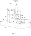
- Fig. 7 shows the adapter element 40 with a rotating device 44 which is mounted on the adapter plate 40.
- the rotating device 44 has the stator 45 and the turntable 46.
- a tip 47 is fixed for holding a workpiece. This is a centered on the axis of rotation D, fixed tip on the turntable 46 (fixed relative to the turntable 46, but rotatable about the axis D).
- a counter-holder 48 is coupled via the coupling means 42.
- the column 49 of the counter-holder is shown transparent, so that the coupling means 42 in Fig. 7 is visible.
- a coupling means 42 complementary coupling means is provided, which has been previously explained and is not shown here.
- the anvil 48 further comprises the cross member or gallows 50, at the end of the rotatable tip 51 is mounted, which points downward. Between the tip 47 on the turntable 46 and the tip 51, a workpiece can be clamped.
- the gallows is slidable in the direction of the axis of rotation D, so that the distance between the tip 47 and the tip 51 is variable.
- the displacement mechanism is not shown in detail.
- both tips 47 and 51 it is necessary for both tips 47 and 51 to lie on the axis of rotation D or to be collinear with respect to the axis of rotation D. At the tip 47 this is achieved by exact positioning on the turntable 46. In the exact positioning of the tip 51 on the axis of rotation D, the adapter element 40 with the coupling means 42 is helpful. For example, the turntable 44 is fixed immovably on the adapter plate 40. Subsequently, the counter-holder 48 can be coupled via the coupling means 42 (and a not shown complementary coupling means on the anvil itself). Thereafter, the anvil tip 51 can be positioned accurately on the rotation axis D of the turntable 44.
- the tip 51 on the anvil 48 is adjustable in position and / or orientation relative to the counter column 49, which may be done in a variety of ways not discussed further herein.
- the coupling means 42 By means of the coupling means 42, a reproducible coupling of the counter-holder 48 to the adapter plate 40 is achieved.
- the counter-holder 48 can be removed and coupled in a reproducible manner at a later arbitrary point in time, wherein the position of the tip 51 is exactly restored on the axis of rotation. It can thus be decided in the measuring operation of the turntable 44, whether a counter-holder should be present as an accessory device or not. If the anvil is not needed, it can, since it can represent a relatively large interference contour and impede the measuring operation, can be removed. At a later date, the counter-holder 48 can be coupled again.
- Fig. 8 shows a two-piece adapter plate 60, which is similar in shape to the adapter plate Fig. 1 ,
- the first part 61 has the fastening means 5a-5e for fixing the plate 60 on a measuring table 201 of a coordinate measuring machine 211 (see FIG Fig. 9 ) on.
- the second part 62 is inserted accurately into a recess 63 in the first part 61.
- the second part 62 may be separable from the first part or permanently connected to the first part. Between the two parts 61, 62 connecting means may be provided. The connection is carried out appropriately.
- a Extension of the part 61 may be possible without causing stress.
- 62 is fixed in a single place, eg in the middle of the turntable.
- the second part 62 is made of a temperature-invariant material and has a lower coefficient of expansion than the material of the first part 61.
- the part 62 is made of an iron-nickel alloy with 64% iron and 36% nickel.
- the coupling means 9 is provided, which has already been described with reference to previous figures. Further, fastening means 8a, 8b, 8c are provided on the part 61, which serve for fastening a turntable and have already been explained with reference to previous figures.
- the adapter plate 60 on the second part 62 of temperature-invariant material also has a coupling means 64 for coupling a rotating device.
- the coupling means 64 is designed analogously to a coupling means 42 in FIG Fig. 6 and has recesses 65a, 65b and 65c. In these recesses may complementarily configured and relatively arranged elevations engage, which are provided on the underside of a rotating device. As a result, a rotating device can be arranged on the adapter plate 60, in the formation of this coupling means also in a reproducible position and / or orientation.
- the second part 62 which forms a portion of the adapter element 60, extends from the location where the coupling means 9 is formed to the location where the rotation axis D of a rotating device attached to the adapter plate 60 strikes the adapter element. This place is designated by the point P.
- a rotation axis D intersects the adapter plate 60 at point P.
- fasteners 8a-8c and coupling means 64 for a rotary device are provided in the temperature invariant region 62.
- This in Fig. 5 gantry type CMM 211 has a measuring stage 201 above which columns 202, 203 are movably arranged in the Y direction of a Cartesian coordinate system.
- the columns 202, 203 together with a cross member 204 form a gantry of the CMM 211.
- the cross member 204 is connected at its opposite ends to the columns 202 and 203, respectively.
- Electric motors not shown cause the linear movement of the columns 202, 203 in the Y direction, along the Y-motion axis. It is z. B. each of the two columns 202, 203 associated with an electric motor.
- the cross member 204 is combined with a cross slide 207, which is air bearing along the cross member 204 in the X direction of the Cartesian coordinate system movable.
- the instantaneous position of the cross slide 207 relative to the cross member 204 can be determined on the basis of a scale graduation 206.
- the movement of the cross member 204 in the X direction, ie along the X-movement axis, is driven by a further electric motor.
- On the cross slide 207 a vertically movable quill 208 is mounted, which is connected at its lower end via a mounting device 210 and a rotating device 205 with a coordinate measuring device 209.
- the coordinate measuring device 209 has an angled probe head 215 on which a stylus 111 with probe ball 121 is detachably arranged.
- the coordinate measuring device 209 may be driven by a further electric motor relative to the cross slide 207 in the Z direction, along the Z motion axis, of the Cartesian coordinate system.
- the electric motors of the CMM, the probe 209 can be moved in the area below the cross member 204 in almost any position.
- the rotary device 205 can rotate the probe 215 about the Z axis so that the stylus 111 can be oriented in different directions.
- a controller that controls the movement of the moving parts of the CMM along the axes of motion.
- the controller is arranged to perform one or more of the steps described in the general description part.
- each adapter element can be attached to the coordinate measuring device 211 or its measuring table 201 to each arrangement, which has already been explained above by way of example and in the general description part.
- step S1 first of all a coordinate of a probing reference point M1 with the measuring system of the coordinate measuring machine 211 is determined. This can be based on Fig. 9 be explained: With the feeler ball 121 is the ball 11 and the ball center M1 (see Fig. 2 ) as the reference point. The coordinates X, Y and Z of the point M1 can thus be determined by touching the ball 11.
- a further step S2 at least one coordinate of the rotation axis D is determined, for example the X and Y coordinates of the rotation axis D at Z height of the touch body reference point M1, ie the center point of the ball 11.
- the coordinates of the reference point M1 and the rotation axis D are known at the level of the reference point M1, the distance of the point M1 from the rotation axis D is known (shortest distance).
- a method can be used which in itself WO 2013/164344 A1 and WO 02090879 A2 is known. In this case, a test specimen is positioned on the turntable of the turntable for positional determination of the axis of rotation and measured in different rotational positions. For details, reference is made to the cited documents.
- Steps S1 and S2 may be performed in any order.
- step S3 step S1 is repeated, ie the position of the reference point M1 determined by touching the ball 11 again. Since the relative position of the reference point M1 and the axis of rotation D, here the distance between the two, is known, at the later time by touching the ball 11 and determining the position of the reference point M1 at the same time the position of the rotation axis D can be determined, which here the X and Y position is equal to the reference point M1. It is therefore no longer necessary at later times to re-measure a rotation axis with a separate test specimen, as explained above at step S2 with reference to cited documents.
- step S4 another probing reference point M2 is determined.
- the relative position or, in this case, the shortest distance from M2 to the axis of rotation D, which was measured in step S2 is also known. This represents additional information for determining the position of the rotation axis D.
- the reference point M2 can be determined again in step S5 by touching the ball 25 and from this information about the position of the rotation axis D can be obtained.
- step S4 is positioned so that the point M1 is positioned on the X-coordinate of the rotation axis D and the point M2 on the Y-coordinate of the rotation axis D.
- steps S3 and S5 the X coordinate and the Y coordinate of the rotation axis D can be directly detected at any later time, as in FIG WO 2013/164344 A1 described.
Landscapes
- Physics & Mathematics (AREA)
- General Physics & Mathematics (AREA)
- A Measuring Device Byusing Mechanical Method (AREA)
- Length Measuring Devices With Unspecified Measuring Means (AREA)
Claims (15)
- Agencement comportant
un élément adaptateur (1 ; 20 ; 30 ; 40) destiné au montage d'un dispositif rotatif (12 ; 44) possédant un axe de rotation (D) dans la chambre de mesure d'un appareil de mesure de coordonnées (211), comportant- au moins un premier moyen de fixation (5a, 5b, 5c, 5d, 5e, 5f ; 32a, 32b, 32c, 32d) et/ou une première zone de fixation (4) pour fixer l'élément adaptateur dans la chambre de mesure,- au moins un deuxième moyen de fixation (8a, 8b, 8c) et/ou une deuxième zone de fixation (7) pour fixer le dispositif rotatif à l'élément adaptateur,dans lequel l'élément adaptateur comporte au moins un moyen d'accouplement (9, 22, 24, 42) pour accoupler un dispositif auxiliaire (12, 25, 26, 48),
dans lequel le moyen d'accouplement est disposé sur l'élément adaptateur de manière adjacente au deuxième moyen de fixation et/ou à la deuxième zone de fixation du dispositif rotatif de manière à ce que le dispositif auxiliaire puisse être positionné à l'état accouplé sur l'élément adaptateur à côté du dispositif rotatif,
un dispositif rotatif (12 ; 44) fixé à l'élément adaptateur,
au moins un dispositif auxiliaire (11, 25, 26, 48), qui est accouplé à l'élément adaptateur et positionné à côté du dispositif rotatif, et qui est sélectionné parmi un corps de mesure (11, 25, 26), un support de capteur ou un dispositif accessoire (48) destiné au dispositif rotatif (12 ; 44). - Agencement selon la revendication 1, dans lequel le dispositif auxiliaire est sélectionné parmi un corps de mesure (11, 25, 26), un support de capteur et/ou un dispositif accessoire (48) destiné au dispositif rotatif.
- Agencement selon la revendication 1 ou 2, dans lequel l'élément adaptateur comporte en tant que moyen d'accouplement :un premier moyen d'accouplement (9) pour accoupler un premier corps de mesure,un deuxième moyen d'accouplement (22) pour accoupler un deuxième corps de mesure.
- Agencement selon la revendication 3, dans lequel l'élément adaptateur comprend en tant que moyen d'accouplement :
un troisième moyen d'accouplement (24) pour accoupler un troisième corps de mesure. - Agencement selon l'une des revendications précédentes, dans lequel l'élément adaptateur comprend en tant que moyen d'accouplement :
un quatrième moyen d'accouplement (42) pour accoupler un dispositif accessoire destiné au dispositif rotatif. - Agencement selon l'une des revendications précédentes, dans lequel le dispositif accessoire est un dispositif (48) destiné à maintenir une pièce à usiner.
- Agencement selon l'une des revendications précédentes, dans lequel l'élément adaptateur (60) est constitué d'un matériau insensible à la température ou comporte une ou plusieurs régions (62) composées d'un matériau insensible à la température.
- Agencement selon l'une des revendications précédentes, dans lequel l'élément adaptateur (60) comprend un moyen d'accouplement (64) pour accoupler le dispositif rotatif à l'élément adaptateur dans une position et/ou une orientation reproductible.
- Agencement selon l'une des revendications 1 à 8, comportant, en tant qu'équipements supplémentaires,- un premier corps de mesure (11) et- un deuxième corps de mesure (25),dans lequel une première ligne virtuelle (L1) s'étendant depuis l'axe de rotation (D) d'un dispositif rotatif (12) fixé à l'élément adaptateur jusqu'à un point de référence de corps de mesure (M1) du premier corps de mesure (11) est perpendiculaire à l'axe de rotation (D), et
une deuxième ligne virtuelle (L2) s'étendant depuis l'axe de rotation (D) jusqu'à un point de référence de corps de mesure (M2) du deuxième corps de mesure (25) et perpendiculaire à l'axe de rotation (D),
forment entre elles un angle de 90° ou sensiblement de 90°. - Agencement selon l'une des revendications précédentes, dans lequel le dispositif rotatif est un plateau rotatif uniaxial, biaxial ou n-axial, où n est un nombre entier, une articulation tournante possédant un axe de rotation, ou une articulation tournante et pivotante possédant deux axes de rotation ou plus.
- Appareil de mesure de coordonnées comprenant un agencement selon l'une des revendications 1-10.
- Procédé de détermination de la position d'un axe de rotation dans le système de coordonnées d'appareil d'un appareil de mesure de coordonnées (211), dans lequel un agencement selon l'une des revendications 1-10 est prévu dans un appareil de mesure de coordonnées (211), dans lequel- l'élément adaptateur (20) de l'agencement est fixé dans l'espace de mesure de l'appareil de mesure de coordonnées (211),- un premier corps de mesure (11), qui possède un premier point de référence de corps de mesure (M1) positionné de manière stationnaire par rapport à l'axe de rotation du dispositif rotatif, est accouplé à l'élément adaptateur en tant que dispositif auxiliaire de l'agencement,et le procédé comprend les étapes suivantes :a) déterminer (S1) au moins une coordonnée du premier point de référence du corps de mesure (M1) au moyen d'un système de mesure (215, 111, 121) de l'appareil de mesure de coordonnées (211),b) déterminer (S2) au moins une coordonnée de l'axe de rotation (D),c) répéter l'étape a) à au moins un instant ultérieur et déterminer ladite au moins une coordonnée de l'axe de rotation (D) audit instant ultérieur à partir de ladite au moins une coordonnée du premier point de référence de corps de mesure (M1).
- Procédé selon la revendication 12, dans lequel le premier point de référence de corps de mesure (M1) est positionné sur la coordonnée X ou à proximité de la coordonnée X de l'axe de rotation (D).
- Procédé selon la revendication 12 ou 13, dans lequel l'agencement comprend :- un deuxième corps de mesure (25) qui possède un deuxième point de référence de corps de mesure (M2) positionné de manière fixe par rapport à l'axe de rotation (D) du dispositif rotatif (12) et qui est accouplé à l'élément adaptateur (20),et le procédé comprend les étapes suivantes :d) déterminer (S4) au moins une coordonnée du deuxième point de référence de corps de mesure (M2) au moyen d'un système de mesure (215, 111, 121) de l'appareil de mesure de coordonnées (211),e) répéter (S5) l'étape d) à au moins un instant ultérieur et déterminer ladite au moins une autre coordonnée de l'axe de rotation (D) audit instant ultérieur à partir de ladite au moins une coordonnée du deuxième point de référence de corps de mesure (M2).
- Procédé selon la revendication 14, dans lequel le deuxième point de référence de corps de mesure (M2) est positionné sur la coordonnée Y ou à proximité de la coordonnée Y de l'axe de rotation (D).
Applications Claiming Priority (2)
| Application Number | Priority Date | Filing Date | Title |
|---|---|---|---|
| DE102015211951 | 2015-06-26 | ||
| PCT/EP2016/064585 WO2016207303A1 (fr) | 2015-06-26 | 2016-06-23 | Élément adapteur pour le montage d'un dispositif rotatif dans la chambre de mesure d'un appareil de mesure de coordonnées |
Publications (2)
| Publication Number | Publication Date |
|---|---|
| EP3314203A1 EP3314203A1 (fr) | 2018-05-02 |
| EP3314203B1 true EP3314203B1 (fr) | 2019-08-07 |
Family
ID=56203385
Family Applications (1)
| Application Number | Title | Priority Date | Filing Date |
|---|---|---|---|
| EP16731897.1A Active EP3314203B1 (fr) | 2015-06-26 | 2016-06-23 | Élément adapteur pour le montage d'un dispositif rotatif dans la chambre de mesure d'un appareil de mesure de coordonnées |
Country Status (5)
| Country | Link |
|---|---|
| US (1) | US10801825B2 (fr) |
| EP (1) | EP3314203B1 (fr) |
| CN (1) | CN107810382B (fr) |
| DE (1) | DE102016211278A1 (fr) |
| WO (1) | WO2016207303A1 (fr) |
Families Citing this family (5)
| Publication number | Priority date | Publication date | Assignee | Title |
|---|---|---|---|---|
| CN107810382B (zh) * | 2015-06-26 | 2020-12-22 | 卡尔蔡司工业测量技术有限公司 | 用于在坐标测量机的测量空间中组装旋转设备的适配器元件 |
| DE102019208946A1 (de) * | 2019-06-19 | 2020-12-24 | Carl Zeiss Industrielle Messtechnik Gmbh | Verfahren und Vorrichtung zur Bestimmung einer Lage einer Drehachse eines Drehtisches sowie Drehtisch und Koordinatenmessgerät |
| DE102020105870B4 (de) | 2020-03-04 | 2023-12-07 | Carl Zeiss Industrielle Messtechnik Gmbh | Koordinatenmessgerät mit einer überwachungseinrichtung sowie verfahren zum betrieb derselben |
| DE102020105871B4 (de) | 2020-03-04 | 2023-01-26 | Carl Zeiss Industrielle Messtechnik Gmbh | Drehtischmodul und koordinatenmessgerät mit drehtischmodul und verfahren zum betrieb derselben |
| EP3954966A1 (fr) | 2020-08-14 | 2022-02-16 | Hexagon Technology Center GmbH | Compensation de table rotative |
Family Cites Families (23)
| Publication number | Priority date | Publication date | Assignee | Title |
|---|---|---|---|---|
| DE2940633C2 (de) * | 1979-10-06 | 1986-01-02 | Ernst Leitz Wetzlar Gmbh, 6330 Wetzlar | Verfahren zur Bestimmung der Drehachse eines Rundtisches in Mehrkoordinaten-Meßgeräten |
| US5410817A (en) * | 1993-05-18 | 1995-05-02 | Budd Co | Measuring tool with concentric point |
| US5832416A (en) * | 1995-09-01 | 1998-11-03 | Brown & Sharpe Manufacturing Company | Calibration system for coordinate measuring machine |
| DE29822001U1 (de) | 1998-12-09 | 1999-03-25 | Fa. Carl Zeiss, 89518 Heidenheim | Prüfkörper zur Kalibrierung eines Koordinatenmeßgerätes |
| DE10159442B4 (de) * | 2000-12-22 | 2006-11-02 | Schott Ag | Kalibrierkörper für ein Koordinatenmessgerät |
| DE10122080A1 (de) | 2001-05-07 | 2002-11-14 | Carl Zeiss 3D Metrology Servic | Verfahren zum Bestimmen von Eigenschaften eines Koordinatenmeßgeräts sowie Testobjekt hierzu |
| EP1478863B1 (fr) * | 2002-02-26 | 2006-07-19 | Faro Technologies Inc. | Adaptateur a vide stable |
| DE202004014884U1 (de) | 2004-09-22 | 2004-12-09 | Klingelnberg Gmbh | Vorrichtung zum Vermessen eines rotationssymmetrischen Präzisionsteiles und Spannvorrichtung |
| US7395607B1 (en) * | 2005-06-14 | 2008-07-08 | Discovery Technology International, Lllp | Rotational and translational microposition apparatus and method |
| US8402668B2 (en) * | 2008-01-07 | 2013-03-26 | Q-Mark Manufacturing, Inc. | Coordinate measuring apparatus |
| CN100562707C (zh) * | 2008-01-11 | 2009-11-25 | 天津大学 | 双目视觉转轴标定方法 |
| JP5448634B2 (ja) | 2009-08-11 | 2014-03-19 | オークマ株式会社 | 機械の誤差同定方法およびプログラム |
| EP2347854A1 (fr) | 2010-01-25 | 2011-07-27 | Peter Lehmann AG | Agencement de table rotative bi-axiale |
| DE102010043798A1 (de) | 2010-01-28 | 2011-09-15 | Carl Zeiss Smt Gmbh | Verfahren zur Ermittlung systematischer geometrischer Abweichungen in einen technischen Mehrkörpersystem |
| DE102010037352B4 (de) | 2010-09-06 | 2012-05-03 | Hexagon Metrology Gmbh | Haltevorrichtung für ein Werkstück |
| WO2013007286A1 (fr) * | 2011-07-08 | 2013-01-17 | Carl Zeiss Industrielle Messtechnik Gmbh | Étalonnage et utilisation de dispositifs rotatifs, en particulier pour faire tourner des boutons et/ou des palpeurs d'appareils de mesure de coordonnées |
| EP2795244B1 (fr) * | 2011-12-21 | 2018-02-07 | Carl Zeiss Industrielle Messtechnik GmbH | Procédé de couplage de deux composants de système d'un appareil de mesure, en particulier d'un appareil de mesure de coordonnées |
| EP2839236B1 (fr) * | 2012-04-19 | 2016-03-30 | Carl Zeiss Industrielle Messtechnik GmbH | Plaque adaptatrice |
| DE102012008296A1 (de) | 2012-04-26 | 2013-10-31 | Klingelnberg Gmbh | Vorrichtung und Verfahren zum Erzeugen, Bearbeiten und/oder Prüfen profiltragender Segmente |
| DE102012207336A1 (de) * | 2012-05-03 | 2013-11-07 | Carl Zeiss Industrielle Messtechnik Gmbh | Verfahren zur Bestimmung der Achse eines Drehtisches bei einem Koordinatenmessgerät. |
| JP6126359B2 (ja) | 2012-11-15 | 2017-05-10 | 株式会社ミツトヨ | 球体形状測定装置 |
| JP5674858B2 (ja) * | 2013-05-10 | 2015-02-25 | ファナック株式会社 | ワイヤ放電加工機の傾斜した回転軸の基準点測定方法および測定治具 |
| CN107810382B (zh) * | 2015-06-26 | 2020-12-22 | 卡尔蔡司工业测量技术有限公司 | 用于在坐标测量机的测量空间中组装旋转设备的适配器元件 |
-
2016
- 2016-06-23 CN CN201680037742.9A patent/CN107810382B/zh active Active
- 2016-06-23 DE DE102016211278.3A patent/DE102016211278A1/de not_active Withdrawn
- 2016-06-23 EP EP16731897.1A patent/EP3314203B1/fr active Active
- 2016-06-23 WO PCT/EP2016/064585 patent/WO2016207303A1/fr not_active Ceased
-
2017
- 2017-12-06 US US15/833,397 patent/US10801825B2/en active Active
Non-Patent Citations (1)
| Title |
|---|
| None * |
Also Published As
| Publication number | Publication date |
|---|---|
| DE102016211278A1 (de) | 2016-12-29 |
| CN107810382A (zh) | 2018-03-16 |
| EP3314203A1 (fr) | 2018-05-02 |
| WO2016207303A1 (fr) | 2016-12-29 |
| US20180100729A1 (en) | 2018-04-12 |
| US10801825B2 (en) | 2020-10-13 |
| CN107810382B (zh) | 2020-12-22 |
Similar Documents
| Publication | Publication Date | Title |
|---|---|---|
| EP2844953B1 (fr) | Procédé de détermination d'un axe d'une table tournante dans un appareil de mesure de coordonnées | |
| DE102013216093B4 (de) | Reduzieren von Fehlern einer Drehvorrichtung, insbesondere für die Bestimmung von Koordinaten eines Werkstücks oder die Bearbeitung eines Werkstücks | |
| EP2834595B1 (fr) | Méthode et appareil pour la réduction des erreurs associées à un dispositif de rotation lors de la détermination des coordonnées d'une pièce ou lors de l'usinage d'une pièce | |
| EP2807447B1 (fr) | Procédé de détermination d'une valeur de correction pour un contrôle d'un palier à fluide, et machine présentant au moins un palier à fluide | |
| EP3274655B1 (fr) | Calibrage d'un dispositif de rotation installé sur une partie mobile d'un appareil de mesure de coordonnées | |
| EP3314203B1 (fr) | Élément adapteur pour le montage d'un dispositif rotatif dans la chambre de mesure d'un appareil de mesure de coordonnées | |
| EP3049758A1 (fr) | Réduction d'erreurs d'un dispositif de rotation qui est utilisée lors de la détermination de coordonnées d'une pièce ou lors de l'usinage d'une pièce | |
| EP2729763A1 (fr) | Correction et/ou prévention d'erreurs lors de la mesure de coordonnées d'une pièce | |
| WO2016015775A1 (fr) | Sonde pour dispositif de mesure de coordonnées | |
| EP3559594A1 (fr) | Dispositif destiné à être utilisé dans une machine-outil à commande numérique conçue pour être employée dans un procédé pour mesurer la machine-outil à commande numérique | |
| DE602005004092T2 (de) | Gerät zum Messen der Oberflächenrauhigkeit oder der Kontur eines Objektes | |
| DE102009024752B4 (de) | Verfahren zum Vermessen und/oder Kalibrieren einer numerisch gesteuerten Werkzeugmaschine | |
| DE102015205569B4 (de) | Kalibrierung eines beweglichen Teils eines Koordinatenmessgeräts oder eines daran angebrachten taktilen Tasters | |
| DE102013208397B4 (de) | Koordinatenmessgerät mit einem zusätzlichen, berührungslos messenden Oberflächenvermessungsgerät | |
| DE10123496A1 (de) | Verzahnungsmessmaschine | |
| EP3265756B1 (fr) | Système permettant de déterminer une erreur de mouvement d'un dispositif de rotation | |
| DE60032635T2 (de) | Verfahren und vorrichtung zum testen von werkzeugmaschinen | |
| DE10319711B4 (de) | Verfahren zur hochgenauen dimensionalen Messung an Messobjekten | |
| DE102015205566A1 (de) | Kalibrierung eines an einem beweglichen Teil eines Koordinatenmessgeräts angebrachten taktilen Tasters | |
| DE102015211950B4 (de) | Adaptereinrichtung zur Montage eines Objekts auf dem Messtisch eines Koordinatenmessgeräts | |
| DE10203002A1 (de) | Vorrichtung und Verfahren zum Kalibrieren eines Roboters | |
| DE102015201582B4 (de) | Ermittlung und Korrektur eines Fehlers einer Drehvorrichtung für ein Koordinatenmessgerät | |
| DE102015226385A1 (de) | Verfahren zur Ermittlung eines Messfehlers und zum Vermessen eines Werkstücks mit einem Koordinatenmessgerät | |
| DE19640674C2 (de) | Verfahren zur Ermittlung und Korrektur der maschinenbedingten Meßfehler eines Koordinatenmeßgerätes von nicht kartesischem und/oder nichtstarrem Aufbau | |
| DE102012207388B4 (de) | Verfahren und Anordnung zur Ermittlung von geometrischen Fehlern eines Koordinatenmessgeräts |
Legal Events
| Date | Code | Title | Description |
|---|---|---|---|
| STAA | Information on the status of an ep patent application or granted ep patent |
Free format text: STATUS: THE INTERNATIONAL PUBLICATION HAS BEEN MADE |
|
| PUAI | Public reference made under article 153(3) epc to a published international application that has entered the european phase |
Free format text: ORIGINAL CODE: 0009012 |
|
| STAA | Information on the status of an ep patent application or granted ep patent |
Free format text: STATUS: REQUEST FOR EXAMINATION WAS MADE |
|
| 17P | Request for examination filed |
Effective date: 20171121 |
|
| AK | Designated contracting states |
Kind code of ref document: A1 Designated state(s): AL AT BE BG CH CY CZ DE DK EE ES FI FR GB GR HR HU IE IS IT LI LT LU LV MC MK MT NL NO PL PT RO RS SE SI SK SM TR |
|
| AX | Request for extension of the european patent |
Extension state: BA ME |
|
| DAV | Request for validation of the european patent (deleted) | ||
| DAX | Request for extension of the european patent (deleted) | ||
| GRAP | Despatch of communication of intention to grant a patent |
Free format text: ORIGINAL CODE: EPIDOSNIGR1 |
|
| STAA | Information on the status of an ep patent application or granted ep patent |
Free format text: STATUS: GRANT OF PATENT IS INTENDED |
|
| INTG | Intention to grant announced |
Effective date: 20190207 |
|
| GRAS | Grant fee paid |
Free format text: ORIGINAL CODE: EPIDOSNIGR3 |
|
| GRAA | (expected) grant |
Free format text: ORIGINAL CODE: 0009210 |
|
| STAA | Information on the status of an ep patent application or granted ep patent |
Free format text: STATUS: THE PATENT HAS BEEN GRANTED |
|
| AK | Designated contracting states |
Kind code of ref document: B1 Designated state(s): AL AT BE BG CH CY CZ DE DK EE ES FI FR GB GR HR HU IE IS IT LI LT LU LV MC MK MT NL NO PL PT RO RS SE SI SK SM TR |
|
| REG | Reference to a national code |
Ref country code: GB Ref legal event code: FG4D Free format text: NOT ENGLISH |
|
| REG | Reference to a national code |
Ref country code: CH Ref legal event code: EP Ref country code: AT Ref legal event code: REF Ref document number: 1164555 Country of ref document: AT Kind code of ref document: T Effective date: 20190815 |
|
| REG | Reference to a national code |
Ref country code: DE Ref legal event code: R096 Ref document number: 502016005970 Country of ref document: DE |
|
| REG | Reference to a national code |
Ref country code: IE Ref legal event code: FG4D Free format text: LANGUAGE OF EP DOCUMENT: GERMAN |
|
| REG | Reference to a national code |
Ref country code: NL Ref legal event code: MP Effective date: 20190807 |
|
| REG | Reference to a national code |
Ref country code: LT Ref legal event code: MG4D |
|
| PG25 | Lapsed in a contracting state [announced via postgrant information from national office to epo] |
Ref country code: FI Free format text: LAPSE BECAUSE OF FAILURE TO SUBMIT A TRANSLATION OF THE DESCRIPTION OR TO PAY THE FEE WITHIN THE PRESCRIBED TIME-LIMIT Effective date: 20190807 Ref country code: SE Free format text: LAPSE BECAUSE OF FAILURE TO SUBMIT A TRANSLATION OF THE DESCRIPTION OR TO PAY THE FEE WITHIN THE PRESCRIBED TIME-LIMIT Effective date: 20190807 Ref country code: BG Free format text: LAPSE BECAUSE OF FAILURE TO SUBMIT A TRANSLATION OF THE DESCRIPTION OR TO PAY THE FEE WITHIN THE PRESCRIBED TIME-LIMIT Effective date: 20191107 Ref country code: NO Free format text: LAPSE BECAUSE OF FAILURE TO SUBMIT A TRANSLATION OF THE DESCRIPTION OR TO PAY THE FEE WITHIN THE PRESCRIBED TIME-LIMIT Effective date: 20191107 Ref country code: PT Free format text: LAPSE BECAUSE OF FAILURE TO SUBMIT A TRANSLATION OF THE DESCRIPTION OR TO PAY THE FEE WITHIN THE PRESCRIBED TIME-LIMIT Effective date: 20191209 Ref country code: HR Free format text: LAPSE BECAUSE OF FAILURE TO SUBMIT A TRANSLATION OF THE DESCRIPTION OR TO PAY THE FEE WITHIN THE PRESCRIBED TIME-LIMIT Effective date: 20190807 Ref country code: NL Free format text: LAPSE BECAUSE OF FAILURE TO SUBMIT A TRANSLATION OF THE DESCRIPTION OR TO PAY THE FEE WITHIN THE PRESCRIBED TIME-LIMIT Effective date: 20190807 Ref country code: LT Free format text: LAPSE BECAUSE OF FAILURE TO SUBMIT A TRANSLATION OF THE DESCRIPTION OR TO PAY THE FEE WITHIN THE PRESCRIBED TIME-LIMIT Effective date: 20190807 |
|
| PG25 | Lapsed in a contracting state [announced via postgrant information from national office to epo] |
Ref country code: RS Free format text: LAPSE BECAUSE OF FAILURE TO SUBMIT A TRANSLATION OF THE DESCRIPTION OR TO PAY THE FEE WITHIN THE PRESCRIBED TIME-LIMIT Effective date: 20190807 Ref country code: LV Free format text: LAPSE BECAUSE OF FAILURE TO SUBMIT A TRANSLATION OF THE DESCRIPTION OR TO PAY THE FEE WITHIN THE PRESCRIBED TIME-LIMIT Effective date: 20190807 Ref country code: AL Free format text: LAPSE BECAUSE OF FAILURE TO SUBMIT A TRANSLATION OF THE DESCRIPTION OR TO PAY THE FEE WITHIN THE PRESCRIBED TIME-LIMIT Effective date: 20190807 Ref country code: ES Free format text: LAPSE BECAUSE OF FAILURE TO SUBMIT A TRANSLATION OF THE DESCRIPTION OR TO PAY THE FEE WITHIN THE PRESCRIBED TIME-LIMIT Effective date: 20190807 Ref country code: GR Free format text: LAPSE BECAUSE OF FAILURE TO SUBMIT A TRANSLATION OF THE DESCRIPTION OR TO PAY THE FEE WITHIN THE PRESCRIBED TIME-LIMIT Effective date: 20191108 Ref country code: IS Free format text: LAPSE BECAUSE OF FAILURE TO SUBMIT A TRANSLATION OF THE DESCRIPTION OR TO PAY THE FEE WITHIN THE PRESCRIBED TIME-LIMIT Effective date: 20191207 |
|
| PG25 | Lapsed in a contracting state [announced via postgrant information from national office to epo] |
Ref country code: TR Free format text: LAPSE BECAUSE OF FAILURE TO SUBMIT A TRANSLATION OF THE DESCRIPTION OR TO PAY THE FEE WITHIN THE PRESCRIBED TIME-LIMIT Effective date: 20190807 |
|
| PG25 | Lapsed in a contracting state [announced via postgrant information from national office to epo] |
Ref country code: PL Free format text: LAPSE BECAUSE OF FAILURE TO SUBMIT A TRANSLATION OF THE DESCRIPTION OR TO PAY THE FEE WITHIN THE PRESCRIBED TIME-LIMIT Effective date: 20190807 Ref country code: RO Free format text: LAPSE BECAUSE OF FAILURE TO SUBMIT A TRANSLATION OF THE DESCRIPTION OR TO PAY THE FEE WITHIN THE PRESCRIBED TIME-LIMIT Effective date: 20190807 Ref country code: IT Free format text: LAPSE BECAUSE OF FAILURE TO SUBMIT A TRANSLATION OF THE DESCRIPTION OR TO PAY THE FEE WITHIN THE PRESCRIBED TIME-LIMIT Effective date: 20190807 Ref country code: DK Free format text: LAPSE BECAUSE OF FAILURE TO SUBMIT A TRANSLATION OF THE DESCRIPTION OR TO PAY THE FEE WITHIN THE PRESCRIBED TIME-LIMIT Effective date: 20190807 Ref country code: EE Free format text: LAPSE BECAUSE OF FAILURE TO SUBMIT A TRANSLATION OF THE DESCRIPTION OR TO PAY THE FEE WITHIN THE PRESCRIBED TIME-LIMIT Effective date: 20190807 |
|
| PG25 | Lapsed in a contracting state [announced via postgrant information from national office to epo] |
Ref country code: CZ Free format text: LAPSE BECAUSE OF FAILURE TO SUBMIT A TRANSLATION OF THE DESCRIPTION OR TO PAY THE FEE WITHIN THE PRESCRIBED TIME-LIMIT Effective date: 20190807 Ref country code: SM Free format text: LAPSE BECAUSE OF FAILURE TO SUBMIT A TRANSLATION OF THE DESCRIPTION OR TO PAY THE FEE WITHIN THE PRESCRIBED TIME-LIMIT Effective date: 20190807 Ref country code: IS Free format text: LAPSE BECAUSE OF FAILURE TO SUBMIT A TRANSLATION OF THE DESCRIPTION OR TO PAY THE FEE WITHIN THE PRESCRIBED TIME-LIMIT Effective date: 20200224 Ref country code: SK Free format text: LAPSE BECAUSE OF FAILURE TO SUBMIT A TRANSLATION OF THE DESCRIPTION OR TO PAY THE FEE WITHIN THE PRESCRIBED TIME-LIMIT Effective date: 20190807 |
|
| REG | Reference to a national code |
Ref country code: DE Ref legal event code: R097 Ref document number: 502016005970 Country of ref document: DE |
|
| PLBE | No opposition filed within time limit |
Free format text: ORIGINAL CODE: 0009261 |
|
| STAA | Information on the status of an ep patent application or granted ep patent |
Free format text: STATUS: NO OPPOSITION FILED WITHIN TIME LIMIT |
|
| PG2D | Information on lapse in contracting state deleted |
Ref country code: IS |
|
| 26N | No opposition filed |
Effective date: 20200603 |
|
| PG25 | Lapsed in a contracting state [announced via postgrant information from national office to epo] |
Ref country code: SI Free format text: LAPSE BECAUSE OF FAILURE TO SUBMIT A TRANSLATION OF THE DESCRIPTION OR TO PAY THE FEE WITHIN THE PRESCRIBED TIME-LIMIT Effective date: 20190807 |
|
| PG25 | Lapsed in a contracting state [announced via postgrant information from national office to epo] |
Ref country code: MC Free format text: LAPSE BECAUSE OF FAILURE TO SUBMIT A TRANSLATION OF THE DESCRIPTION OR TO PAY THE FEE WITHIN THE PRESCRIBED TIME-LIMIT Effective date: 20190807 |
|
| REG | Reference to a national code |
Ref country code: CH Ref legal event code: PL |
|
| GBPC | Gb: european patent ceased through non-payment of renewal fee |
Effective date: 20200623 |
|
| PG25 | Lapsed in a contracting state [announced via postgrant information from national office to epo] |
Ref country code: LU Free format text: LAPSE BECAUSE OF NON-PAYMENT OF DUE FEES Effective date: 20200623 |
|
| REG | Reference to a national code |
Ref country code: BE Ref legal event code: MM Effective date: 20200630 |
|
| PG25 | Lapsed in a contracting state [announced via postgrant information from national office to epo] |
Ref country code: FR Free format text: LAPSE BECAUSE OF NON-PAYMENT OF DUE FEES Effective date: 20200630 Ref country code: IE Free format text: LAPSE BECAUSE OF NON-PAYMENT OF DUE FEES Effective date: 20200623 Ref country code: GB Free format text: LAPSE BECAUSE OF NON-PAYMENT OF DUE FEES Effective date: 20200623 Ref country code: LI Free format text: LAPSE BECAUSE OF NON-PAYMENT OF DUE FEES Effective date: 20200630 Ref country code: CH Free format text: LAPSE BECAUSE OF NON-PAYMENT OF DUE FEES Effective date: 20200630 |
|
| PG25 | Lapsed in a contracting state [announced via postgrant information from national office to epo] |
Ref country code: BE Free format text: LAPSE BECAUSE OF NON-PAYMENT OF DUE FEES Effective date: 20200630 |
|
| PG25 | Lapsed in a contracting state [announced via postgrant information from national office to epo] |
Ref country code: MT Free format text: LAPSE BECAUSE OF FAILURE TO SUBMIT A TRANSLATION OF THE DESCRIPTION OR TO PAY THE FEE WITHIN THE PRESCRIBED TIME-LIMIT Effective date: 20190807 Ref country code: CY Free format text: LAPSE BECAUSE OF FAILURE TO SUBMIT A TRANSLATION OF THE DESCRIPTION OR TO PAY THE FEE WITHIN THE PRESCRIBED TIME-LIMIT Effective date: 20190807 |
|
| PG25 | Lapsed in a contracting state [announced via postgrant information from national office to epo] |
Ref country code: MK Free format text: LAPSE BECAUSE OF FAILURE TO SUBMIT A TRANSLATION OF THE DESCRIPTION OR TO PAY THE FEE WITHIN THE PRESCRIBED TIME-LIMIT Effective date: 20190807 |
|
| REG | Reference to a national code |
Ref country code: AT Ref legal event code: MM01 Ref document number: 1164555 Country of ref document: AT Kind code of ref document: T Effective date: 20210623 |
|
| PG25 | Lapsed in a contracting state [announced via postgrant information from national office to epo] |
Ref country code: AT Free format text: LAPSE BECAUSE OF NON-PAYMENT OF DUE FEES Effective date: 20210623 |
|
| P01 | Opt-out of the competence of the unified patent court (upc) registered |
Effective date: 20230525 |
|
| PGFP | Annual fee paid to national office [announced via postgrant information from national office to epo] |
Ref country code: DE Payment date: 20250618 Year of fee payment: 10 |