EP3314663B1 - Transistors à haute mobilité d'électrons avec isolation sous-ailette localisée - Google Patents
Transistors à haute mobilité d'électrons avec isolation sous-ailette localisée Download PDFInfo
- Publication number
- EP3314663B1 EP3314663B1 EP15896564.0A EP15896564A EP3314663B1 EP 3314663 B1 EP3314663 B1 EP 3314663B1 EP 15896564 A EP15896564 A EP 15896564A EP 3314663 B1 EP3314663 B1 EP 3314663B1
- Authority
- EP
- European Patent Office
- Prior art keywords
- fin
- sub
- crystalline
- iii
- trench
- Prior art date
- Legal status (The legal status is an assumption and is not a legal conclusion. Google has not performed a legal analysis and makes no representation as to the accuracy of the status listed.)
- Active
Links
Images



Classifications
-
- H—ELECTRICITY
- H10—SEMICONDUCTOR DEVICES; ELECTRIC SOLID-STATE DEVICES NOT OTHERWISE PROVIDED FOR
- H10D—INORGANIC ELECTRIC SEMICONDUCTOR DEVICES
- H10D30/00—Field-effect transistors [FET]
- H10D30/60—Insulated-gate field-effect transistors [IGFET]
- H10D30/67—Thin-film transistors [TFT]
- H10D30/6704—Thin-film transistors [TFT] having supplementary regions or layers in the thin films or in the insulated bulk substrates for controlling properties of the device
- H10D30/6706—Thin-film transistors [TFT] having supplementary regions or layers in the thin films or in the insulated bulk substrates for controlling properties of the device for preventing leakage current
-
- H—ELECTRICITY
- H10—SEMICONDUCTOR DEVICES; ELECTRIC SOLID-STATE DEVICES NOT OTHERWISE PROVIDED FOR
- H10D—INORGANIC ELECTRIC SEMICONDUCTOR DEVICES
- H10D30/00—Field-effect transistors [FET]
- H10D30/40—FETs having zero-dimensional [0D], one-dimensional [1D] or two-dimensional [2D] charge carrier gas channels
- H10D30/47—FETs having zero-dimensional [0D], one-dimensional [1D] or two-dimensional [2D] charge carrier gas channels having two-dimensional [2D] charge carrier gas channels, e.g. nanoribbon FETs or high electron mobility transistors [HEMT]
-
- H—ELECTRICITY
- H10—SEMICONDUCTOR DEVICES; ELECTRIC SOLID-STATE DEVICES NOT OTHERWISE PROVIDED FOR
- H10D—INORGANIC ELECTRIC SEMICONDUCTOR DEVICES
- H10D30/00—Field-effect transistors [FET]
- H10D30/01—Manufacture or treatment
- H10D30/015—Manufacture or treatment of FETs having heterojunction interface channels or heterojunction gate electrodes, e.g. HEMT
-
- H—ELECTRICITY
- H10—SEMICONDUCTOR DEVICES; ELECTRIC SOLID-STATE DEVICES NOT OTHERWISE PROVIDED FOR
- H10D—INORGANIC ELECTRIC SEMICONDUCTOR DEVICES
- H10D30/00—Field-effect transistors [FET]
- H10D30/01—Manufacture or treatment
- H10D30/021—Manufacture or treatment of FETs having insulated gates [IGFET]
-
- H—ELECTRICITY
- H10—SEMICONDUCTOR DEVICES; ELECTRIC SOLID-STATE DEVICES NOT OTHERWISE PROVIDED FOR
- H10D—INORGANIC ELECTRIC SEMICONDUCTOR DEVICES
- H10D30/00—Field-effect transistors [FET]
- H10D30/01—Manufacture or treatment
- H10D30/021—Manufacture or treatment of FETs having insulated gates [IGFET]
- H10D30/024—Manufacture or treatment of FETs having insulated gates [IGFET] of fin field-effect transistors [FinFET]
-
- H—ELECTRICITY
- H10—SEMICONDUCTOR DEVICES; ELECTRIC SOLID-STATE DEVICES NOT OTHERWISE PROVIDED FOR
- H10D—INORGANIC ELECTRIC SEMICONDUCTOR DEVICES
- H10D30/00—Field-effect transistors [FET]
- H10D30/01—Manufacture or treatment
- H10D30/021—Manufacture or treatment of FETs having insulated gates [IGFET]
- H10D30/031—Manufacture or treatment of FETs having insulated gates [IGFET] of thin-film transistors [TFT]
-
- H—ELECTRICITY
- H10—SEMICONDUCTOR DEVICES; ELECTRIC SOLID-STATE DEVICES NOT OTHERWISE PROVIDED FOR
- H10D—INORGANIC ELECTRIC SEMICONDUCTOR DEVICES
- H10D30/00—Field-effect transistors [FET]
- H10D30/60—Insulated-gate field-effect transistors [IGFET]
- H10D30/62—Fin field-effect transistors [FinFET]
-
- H—ELECTRICITY
- H10—SEMICONDUCTOR DEVICES; ELECTRIC SOLID-STATE DEVICES NOT OTHERWISE PROVIDED FOR
- H10D—INORGANIC ELECTRIC SEMICONDUCTOR DEVICES
- H10D30/00—Field-effect transistors [FET]
- H10D30/60—Insulated-gate field-effect transistors [IGFET]
- H10D30/67—Thin-film transistors [TFT]
- H10D30/6729—Thin-film transistors [TFT] characterised by the electrodes
- H10D30/673—Thin-film transistors [TFT] characterised by the electrodes characterised by the shapes, relative sizes or dispositions of the gate electrodes
- H10D30/6735—Thin-film transistors [TFT] characterised by the electrodes characterised by the shapes, relative sizes or dispositions of the gate electrodes having gates fully surrounding the channels, e.g. gate-all-around
-
- H—ELECTRICITY
- H10—SEMICONDUCTOR DEVICES; ELECTRIC SOLID-STATE DEVICES NOT OTHERWISE PROVIDED FOR
- H10D—INORGANIC ELECTRIC SEMICONDUCTOR DEVICES
- H10D30/00—Field-effect transistors [FET]
- H10D30/60—Insulated-gate field-effect transistors [IGFET]
- H10D30/67—Thin-film transistors [TFT]
- H10D30/674—Thin-film transistors [TFT] characterised by the active materials
- H10D30/675—Group III-V materials, Group II-VI materials, Group IV-VI materials, selenium or tellurium
-
- H—ELECTRICITY
- H10—SEMICONDUCTOR DEVICES; ELECTRIC SOLID-STATE DEVICES NOT OTHERWISE PROVIDED FOR
- H10D—INORGANIC ELECTRIC SEMICONDUCTOR DEVICES
- H10D30/00—Field-effect transistors [FET]
- H10D30/60—Insulated-gate field-effect transistors [IGFET]
- H10D30/67—Thin-film transistors [TFT]
- H10D30/6757—Thin-film transistors [TFT] characterised by the structure of the channel, e.g. transverse or longitudinal shape or doping profile
-
- H—ELECTRICITY
- H10—SEMICONDUCTOR DEVICES; ELECTRIC SOLID-STATE DEVICES NOT OTHERWISE PROVIDED FOR
- H10D—INORGANIC ELECTRIC SEMICONDUCTOR DEVICES
- H10D62/00—Semiconductor bodies, or regions thereof, of devices having potential barriers
- H10D62/10—Shapes, relative sizes or dispositions of the regions of the semiconductor bodies; Shapes of the semiconductor bodies
- H10D62/117—Shapes of semiconductor bodies
- H10D62/118—Nanostructure semiconductor bodies
- H10D62/119—Nanowire, nanosheet or nanotube semiconductor bodies
- H10D62/121—Nanowire, nanosheet or nanotube semiconductor bodies oriented parallel to substrates
Definitions
- Non-silicon semiconductor materials including compound semiconductor materials (e.g., GaAs, InP, InGaAs, InAs, and III-N materials). These non-silicon material systems may be employed in high electron mobility transistors (HEMT), some of which may be metal oxide semiconductor field effect transistors (MOSFET).
- HEMT high electron mobility transistors
- MOSFET metal oxide semiconductor field effect transistors
- One technique for fabricating high electron mobility transistors includes forming a non-silicon crystalline device region (e.g., a transistor channel region) over an intermediate supporting structure comprising a material distinct from that of the channel device region and the substrate.
- Materials for the device region and an underlying sub-structure may form a heterostructure.
- the heterostructure demarks a boundary between complementary semiconductor materials (e.g., an n-type channel region disposed on a p-type sub-channel region), transistors utilizing the channel region may exhibit relatively poor short channel effect (SCE). Device architectures that further reduced SCE in such devices are therefore desirable.
- SCE short channel effect
- Coupled may be used to indicate that two or more elements are in direct physical, optical, or electrical contact with each other.
- Connected may be used to indicate that two or more elements are in direct physical, optical, or electrical contact with each other.
- Coupled may be used to indicated that two or more elements are in either direct or indirect (with other intervening elements between them) physical or electrical contact with each other, and/or that the two or more elements co-operate or interact with each other (e.g., as in a cause an effect relationship).
- one material or material disposed over or under another may be directly in contact or may have one or more intervening materials.
- one material disposed between two materials or materials may be directly in contact with the two layers or may have one or more intervening layers.
- a first material or material "on” a second material or material is in direct contact with that second material/material. Similar distinctions are to be made in the context of component assemblies.
- heteroepitaxial structures including an elevated crystalline fin structure extending from a crystalline sub-fin structure over a crystalline substrate.
- non-silicon devices e.g., III-V channel field effect transistors
- Silicon devices e.g., silicon channel field effect transistors
- a sub-fin isolation material is formed in a manner localized to below a non-silicon transistor channel region of the fin structure. This isolation material may reduce leakage current between source and drain that would otherwise pass through the crystalline sub-fin material. Greater electrical isolation between source and drain ends of the fin structure may improve the SCE of a non-silicon transistor utilizing fin material as a gate electrode-coupled conduction channel.
- some embodiments of the highly localized sub-fin isolation structures described herein may be more manufacturable than less-localized isolation structures, such as silicon-on-insulator (SOI) substrates that may require layer transfer and/or wafer bonding.
- SOI silicon-on-insulator
- Embodiments of the sub-fin isolation material structures described herein also have advantages over junction isolation structures, which generally require implants that are difficult to control for current transistor architectures, and also typically introduce significant parasitic capacitance.
- a portion of crystalline sub-fin material may be laterally etched, undercutting crystalline fin material subsequent to heteroepitaxially forming the crystalline fin material from a seeding surface of the sub-fin.
- the undercut may be backfilled with the sub-fin isolation material.
- a gate stack may then be formed over the fin, landing on the sub-fin isolation material or a surrounding field dielectric material.
- formation of the sub-fin isolation is integrated into a self-aligned gate stack replacement process to improve non-silicon transistor performance with little additional fabrication complexity.
- FIG. 1A is a plan view of a System-on-Chip (SoC) 10 including a pair of non-silicon transistors 101 and 102 with sub-fin isolation 130, in accordance with some embodiments.
- Non-silicon transistors 101 and 102 are N-type (NMOS) and disposed over a silicon substrate 105.
- SoC 10 may further include P-type (and N-type) silicon-based MOSFETs (not depicted) disposed over a second substrate surface region.
- Each transistor 101, 102 includes a non-silicon monocrystalline heteroepitaxial fin (hetero-fin) structure 103 having a shortest length in a first dimension (e.g., x ) and a longest length in a second dimension (e.g. y ).
- hetero-fin structure 103 includes a device layer, referred to herein as the "fin,” disposed on a support, referred to herein as the "sub-fin.”
- transistors 101 and 102 are substantially identical structures configured into electrical parallel for greater current carrying capacity.
- a single gate electrode stack 170 forms a first stripe extending in the x -dimension over a channel region of the fin in hetero-fin structures 103.
- Source/drain contact metallization 150 forms second stripes extending in the x -dimension to couple to source and drain ends of the fin in hetero-fin structures 103.
- a sub-fin isolation material has a lateral dimension parallel to a source-drain length of the hetero-fin structure that is at least as large as a length of the fin channel region over which the gate electrode stack is disposed.
- hetero-fin structures 103 are illustrated in thin dashed line to indicate they are substantially covered by an overlying interlayer dielectric material 180, gate stack 170, and source/drain contact metallization 150.
- Sub-fin isolation 130 is illustrated in thick dashed line. As visible from the plan view, sub-fin isolation 130 is localized to a channel region of hetero-fins 103 that is electrostatically coupled to gate electrode stack 170.
- Sub-fin isolation material 130 may be considered a sub-fin "source/drain" isolation structure localized to only a portion of the sub-fin structure sufficient to reduce a source-drain conduction path through the sub-fin portion of hetero-fins 103.
- sub-fin isolation material 130 has a lateral length L 1 in the y- dimension that is larger than a length L 2 of gate stack 170.
- a region of hetero-fin 103 referred to herein as the "channel region" is located where the gate stack length L 2 contacts underlying fin material.
- sub-fin isolation material has a lateral dimension orthogonal to the source-drain length of the fin ( x -dimension) that is substantially equal to a width of the fin.
- hetero-fin 103 has a fin width W 1 and sub-fin isolation material 130 has a lateral width W 2 that is substantially equal to fin width W 1 .
- lateral width W 2 may be controlled as a function of how sub-fin isolation material 130 is integrated with the fabrication of other transistor components, such as gate electrode stack 170.
- Sub-fin isolation structures in accordance with some embodiments, for example, may be readily integrated into a gate replacement process such that edges of a sub-fin isolation structure may be self-aligned to sidewalls of a hetero-fin, or may be self-aligned to sidewalls of a gate electrode stack.
- FIG. 1B is a plan view of a System-on-Chip (SoC) 20 including a pair of non-silicon transistors 101 and 102 with sub-fin isolation 130, again disposed over a substrate 105.
- SoC System-on-Chip
- sub-fin isolation 130 has a lateral width W 2 that is significantly larger than fin width W 1 with a portion of sub-fin isolation material 130 extending beyond opposite sidewalls of hetero-fin 103.
- sub-fin isolation material 130 extends beyond opposite sidewalls of hetero-fin 103 by substantially the same amount as does gate electrode stack 170.
- gate electrode stack edge 171 is aligned with sub-fin isolation material edge 131.
- sub-fin isolation structure 130 comprises a continuous stripe of amorphous isolation material intersecting the plurality of fin structures to separate each fin channel region from a crystalline sub-fin material that might otherwise conduct significant leakage current.
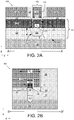
- FIG. 2A illustrates a cross-sectional view through a length of a channel region and source/drain regions of transistor 101 along the A-A' line depicted in FIG. 1A , in accordance with some embodiments.
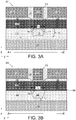
- FIG. 2B illustrates a cross-sectional view through a width of a channel region and a gate electrode of transistor 101 along the B-B' line depicted in FIG. 1A , in accordance with some embodiments.
- a length of hetero-fin 103 is disposed on a monocrystalline substrate 105.
- Hetero-fin 103 includes a monocrystalline sub-fin material 110 that is disposed on substrate 105, and a monocrystalline fin material 120 that is disposed on sub-fin material 110.
- raised doped source/drain material 140 is disposed on crystalline fin material 120.
- raised doped source/drain material 140 is disposed on fin material 110 (e.g., where ends of fin material 120 has been removed and regrown).
- Raised doped source/drain material 140 may be any material suitable for ohmic contact to fin material 120, such as, but not limited to, InAs.
- raised doped source/drain material 140 is single crystalline.
- Contact metallization 150 is in contact with raised doped source/drain material 140 and is electrically isolated from gate stack 170 by interlayer dielectric 180 and/or lateral spacers of gate dielectric 172.
- substrate 105 is silicon (Si), which is advantageous for monolithic integration of III-V MOS transistor 101 with conventional silicon-channeled MOSFETs, for example with the III-V MOS transistor 101 being an NMOS device and the silicon MOSFET being a PMOS device to enable CMOS integrated circuitry.
- Crystallographic orientation of a substantially monocrystalline substrate 105 in exemplary embodiments is (100), (111), or (110). However, other crystallographic orientations are also possible.
- the substrate working surface may be miscut, or offcut 2-10° toward [110], to facilitate nucleation of heteroepitaxial sub-fin material 110.
- Sub-fin material 110 may help to accommodate lattice mismatch between the materials selected for fin material 120 and substrate 105, and/or provide junction isolation fin material 120 and substrate 105.
- sub-fin material 110 is a material other than that of the substrate, with the interface between them being a first heterojunction associated with hetero-fin 103.
- Sub-fin material 110 a first group III-V compound semiconductor material (e.g., GaAs, InP, InAs, InGaAs, AlGaAs, GaP, AlAs, InGaP).
- fin material 120 is to serve as a device layer, for example including the carrier conduction channel region denoted in FIG. 2A by dashed lines 205.
- Channel region 205 is to be modulated through the field effect applied by an overlying gate electrode 173.
- Fin material 120 comprises a material other than that of the sub-fin material 110, with the interface between them being a second heterojunction associated with hetero-fin 103.
- fin material 120 is a second group III-V compound semiconductor material (e.g., GaAs, InP, InAs, InGaAs, AlGaAs, GaP, AlAs, InGaP).
- the two hetero-fin materials may also be of complementary dopant type (e.g., a p-type III-V sub-fin and an n-type III-V fin).
- III-V fin structures and finFET embodiments are employed consistently herein for the sake of clarity of discussion, it is expected one of skill in the art familiar with the characteristics of alternate semiconductor material systems will be able to successfully apply the techniques described herein to other heteroepitaxial fin structures absent some specific a priori knowledge of a salient incompatibility between the exemplary III-V embodiments and the alternate material systems.
- alternative non-silicon material systems such as but not limited to, the III-N material system (e.g., AlN, GaN, AlGaN, InAlGaN) may also be amenable to the techniques and architectures described herein.
- sub-fin isolation material 130 is disposed immediately below channel region 205, occupying a recess in sub-fin material 110 that extends across the hetero-fin width.
- sub-fin isolation material 130 has a lateral width that is at least equal to fin width W 1 .
- Channel region 205 is therefore completely separated from the sub-fin material 110 by sub-fin isolation material 130.
- sub-fin isolation material 130 has opposite sidewalls or edges substantially aligned with sidewalls or edges of fin material 120 (and sub-fin material 110). In other embodiments also illustrated by FIG.
- sub-fin isolation material 130 has a sidewall or edge substantially aligned with sidewall or edge of gate stack 170 (e.g., aligned with gate dielectric 172 and/or gate electrode 173 depending on technique employed to form gate stack 170).
- sub-fin isolation material 130 forms an interface 260 with dielectric trench material 115.
- both sub-fin material 110 and sub-fin isolation material 130 may be embedded within dielectric trench material 115.
- sub-fin material 110 may be bifurcated by sub-fin isolation material 130 such that fin material 120 is essentially disposed on two distinct crystalline sub-fin portions (not depicted).
- sub-fin material 110 remains continuous over the length of fin material 120 with sub-fin isolation material 130 having a maximum z-thickness of T 1 while sub-fin material 110 necks-down to a minimum z-thickness of T 2 .
- thickness T 1 /T 2 may be selected to achieve any desired reduction in sub-fin source/drain current.
- T 1 is at least equal to T 2 , and more advantageously greater than T 2 .
- the introduction of sub-fin isolation material 130 contacting crystalline fin surface 135 of fin material 120 may render surface leakage the dominant mode of source/drain leakage.
- length L 1 of the surface 135 contacting sub-fin isolation material 130 is at least equal to channel region length L 2 , and is advantageously greater than L 2 .
- sub-fin isolation material 130 may therefore be selected to best passivate crystalline fin surface 135.
- sub-fin isolation material 130 is a dielectric, such as, but not limited to silicon oxides (e.g., SiO 2 , or siloxane derivatives), or polymer dielectrics(e.g., benzocyclobutene, porous methyl silsesquioxane).
- sub-fin isolation material 130 comprises a composite dielectric film stack including more than one material layer.
- sub-fin isolation material 130 includes both gate dielectric material 172 and a bulk-fill dielectric material 132.
- Gate dielectric material 172 forms a low-leakage interface 135 with crystalline fin material 120.
- Bulk-fill dielectric material 132 backfills any remain recess in crystalline sub-fin material 110.
- Gate dielectric material 172 may be any known to be suitable for the composition of fin material 120, such as, but not limited to a metal oxide (e.g., Al 2 O 3 , HFO 2 , etc.).
- Bulk-fill dielectric material 132 may be any conventional material, or a low-k material having a relative dielectric constant less than 2.5.
- bulk-fill dielectric material 132 may be any of silicon oxides (e.g., SiO 2 , or siloxane derivatives), polymer dielectrics (e.g., benzocyclobutene, porous methyl silsesquioxane), or the like.
- gate metal 173 does not back fill the sub-fin recess
- gate dielectric 172 is employed merely as a surface passivation.
- the presence of bulk-fill dielectric material 132 ensures low gate electrode fringe capacitance, in part by ensuring gate metal 173 does not backfill any recess not sealed by gate dielectric 172.
- a hetero-fin structure further includes a monocrystalline interfacial material between the device layer and sub-fin.
- This interfacial material may be selected to facilitate forming a low leakage interface with a sub-fin isolation material.
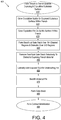
- FIG. 3B illustrates a cross-sectional view through a length of a transistor channel region and source/drain regions of transistor 202 along the A-A' line substantially as depicted in FIG. 1A (or FIG. 1B ), in accordance with some embodiments.
- monocrystalline interfacial material 380 is retained as part of crystalline fin material 120.
- the composition of interfacial material 380 may be selected to have a large carrier band offset from that of the crystalline fin material.
- interfacial material 380 may be AlAs, AlGaAs, or GaP. Interfacial material 380 may further have a z-thickness significantly less than the z-thickness of sub-fin material 110, and in some embodiments is significantly less than even minimum sub-fin z-thickness T 2 . Source/drain leakage through interfacial material 380 may then be insignificant. Indeed, interfacial material 380 may be so thin (e.g., only 1-3 nm) as to be carrier depleted. Leakage at fin/isolation interface 335 may then be insignificant.
- sub-fin isolation dielectric may be any conventional or low-k material, such as but not limited to silicon oxides (e.g., SiO 2 , or siloxane derivatives), or polymer dielectrics(e.g., benzocyclobutene, porous methyl silsesquioxane), and/or metal oxides as a function of other integration choices.
- silicon oxides e.g., SiO 2 , or siloxane derivatives
- polymer dielectrics e.g., benzocyclobutene, porous methyl silsesquioxane
- metal oxides as a function of other integration choices.
- sub-fin isolation 130 forms an interface with one or more sub-fin crystallographic facets 210.
- sub-fin crystallographic facets 210 are indicative of a highly chemical etchant capable of undercutting fin material 120.
- sub-fin material 110 is further recessed below a level of dielectric trench material 115 surrounding sub-fin material 110, for example functioning as field isolation.
- sub-fin isolation material 130 extends beyond fin material width W 1
- sub-fin isolation material has a greater z-thickness below fin material 120 than where sub-fin isolation material 130 extends beyond fin material 120.
- this feature along with the gate stack edge alignment, is indicative of recess etching sub-fin material 110 and backfilling the recess with sub-fin isolation material 130 during a gate-replacement process.
- FIG. 4 is a flow diagram illustrating a method 401 for fabricating a non-silicon field effect transistor with localized sub-fin isolation, in accordance with some embodiments.
- Method 401 may be utilized to form the transistors 101, 102 ( FIG. 1A ), for example.
- FIG. 5A, 6A, 7A , 8A, 9A, 10A , 11A, 12A, 13A , 14A, 15A, and 16A are cross-sectional views depicting a length of a channel region and source/drain regions of a transistor with localized sub-fin isolation evolving as the method illustrated in FIG.
- FIG. 5B, 6B, 7B , 8B, 9B, 10B , 11B, 12B, 13B , 14B, 15B, and 16B are cross-sectional views depicting a corresponding width of the channel region and gate electrode of a transistor with localized sub-fin isolation evolving as the method illustrated in FIG. 4 is performed, in accordance with some embodiments.
- Method 401 begins with forming a heteroepitaxial fin structure.
- aspect ratio trapping (ART) is utilized to achieve acceptable crystal quality in the heteroepitaxial fin material.
- the ART technique described herein in the context of operations 410, 420 and 430 is an example of additive heteroepitaxial fin fabrication, which may advantageously reduce the effects of thermal mismatch across various heterojunctions.
- a conventional subtractive technique may be employed in which a blanket epitaxial film stack grown over the substrate or bonded/transferred to the substrate is etched into fin structures similarly amenable to subsequent operations of method 401 where localized sub-fin isolation material is introduced.
- the ART process begins at operation 410 where a trench is formed in a trench material disposed over a substrate.
- the trench may be etched completely through a z-thickness of the trench material, exposing a crystalline substrate surface that is to seed a subsequent epitaxial growth.
- a trench 510 is anistropically etched into trench material 115, exposing a portion of substrate 105 at the bottom of trench 510.
- the exposed portion of substrate 105 is recessed etched.
- a recess with positively sloped sidewalls is etched into substrate 105, which may further enhance trapping of crystalline defects (e.g., dislocations) in a subsequently grown crystalline sub-fin material.
- Trench material 115 may be any dielectric material known suitable as a field isolation or shallow trench isolation material, such as, but not limited, to silicon dioxide.
- the aspect ratio (z-depth : y-dimension) is advantageously at least 2:1 and more advantageously 3:1, or more.
- trench 510 has a CD of between 10 and 200 nm.
- trench material z-thickness and CD may be scaled as needed to maintain a workable aspect ratio for a predetermine fin height selected for a desired transistor current carrying width.
- method 401 continues at operation 420 where the monocrystalline sub-fin is epitaxially grown from the substrate surface exposed at the bottom of the trench formed at operation 410.
- Any epitaxial growth technique such as, but not limited to, metal-organic chemical vapor deposition (MOCVD), molecular beam epitaxy (MBE), or hydride vapor phase epitaxy (HVPE) may be utilized at operation 410.
- MOCVD metal-organic chemical vapor deposition
- MBE molecular beam epitaxy
- HVPE hydride vapor phase epitaxy
- sub-fin material 110 is epitaxially grown selectively to the substrate seeding surface to partially back fill trench 510.
- feed gases and other epitaxial process control parameters are changed to epitaxially grow fin material from the sub-fin surface still contained within the trench.
- Operations 420 and 430 may be performed in a continuous manner with an in-situ change in growth parameters.
- operation 420 may further include multiple growth parameter/feed gas changes following any known technique.
- the surrounding trench material may be recessed to a desired level to expose sidewalls of the fin material. In the exemplary embodiment illustrated in FIG.
- trench material 115 is recess etched (e.g., with a blanket timed etch). More or less of hetero-fin103 may be exposed during recess etch of trench material 115. In the illustrative embodiment, trench material 115 is recessed sufficiently to fully expose fin material 120 without exposing sub-fin material 110 in preparation for a raised source/drain regrowth.
- a gate stack mandrel is formed over a fin channel region.
- Any known sacrificial gate structure and fabrication techniques may be employed at operation 440.
- operation 440 entails dielectric deposition and planarization, as well as patterning an opening in the dielectric exposing the fin structure, and backfilling the opening with a sacrificial gate.
- sacrificial gate material is blanket deposited and patterned into gate mandrel stripes.
- a gate stack mandrel including sacrificial gate material 870 is formed over fin material 120 using any conventional technique.
- Sacrificial gate material 870 is formed on at least two sidewalls of fin material 120 and lands on trench material 115. Spacer dielectric 871 may also be formed using any conventional technique. For the embodiment depicted in FIG. 8B , sacrificial gate material 870 does not cover any portion of sidewalls of sub-fin material 110, but it may as function of how much trench material 115 is recessed. Subsequent to forming the gate mandrel, doped regions are formed at the source/drain ends of fin material 120. In some embodiments, a raised source/drain region is formed by depositing a heavily-doped semiconductor of any composition suitable for fin material 120. In the exemplary embodiment illustrated in FIG.
- an epitaxial process is employed to form monocrystalline raised source/drain regions 140.
- An interlayer dielectric (ILD) 180 is then deposited over raised source/drain regions 140 and planarized with the gate mandrel, as further depicted in FIG. 10A, 10B .
- method 401 continues at operation 450 where the gate mandrel is removed selectively relative to the surrounding dielectric material, exposing fin material and trench material. Any conventional technique may be used at operation 450 to remove the sacrificial gate material(s). Following gate mandrel removal, exposed trench material may be further recessed, if necessary, to expose at least a portion of sub-fin material. In the example further illustrated in FIG. 11A, 11B , trench material 115 is recessed to expose portion of sub-fin material 110. This recess is self-aligned to the dimensions of the extracted gate mandrel.
- Exposed sub-fin material is laterally etched at operation 460 ( FIG. 4 ) to undercut the exposed fin region.
- the sub-fin etch is advantageously self-aligned to the dimensions of the extracted gate mandrel.
- a crystallographic etchant having selectivity to sub-fin material 110 over fin material 120 is employed at operation 460.
- a chemical etchant selective to InP over InGaAs e.g., hydrochloric acid/water, etc.
- undercuts exposed InGaAs fin material and form one or more etch facets in an InP sub-fin material As further illustrated in FIG.
- the etchant laterally undercuts the fin material 120 forming recess 1230.
- the etchant further recesses a portion of the sub-fin material 110 below surrounding trench material 115.
- the etchant further laterally undercuts a length of sub-fin 110 that is greater than a length L 3 of the gate mandrel.
- the undercut fin material is backfilled with sub-fin isolation material.
- the composition of the sub-fin isolation material is distinct from the trench material, facilitating a subsequent selective recessing of the selective sub-fin isolation material.
- operation 470 entails depositing metal oxide by ALD or CVD.
- operation 470 entails depositing a silicon oxide by CVD.
- operation 470 entails a CVD dielectric deposition and reflow process.
- sub-fin isolation material 130 completely backfills the recessed sub-fin material 110 and is planarized to a level covering over interlayer dielectric 180.
- Method 401 proceeds to operation 480 where a gate stack is formed over at least two sidewalls of the fin material.
- operation 480 entails recessing the sub-fin isolation dielectric material selectively to the surrounding interlayer dielectric to expose a desired portion of the fin material.
- isolation material 130 is etched to form a gate stack recess 1470.
- isolation material 130 is only partially recessed to the dashed line 1471, exposing only fin material 120.
- isolation material 130 is more completely removed with any anisotropic etch process known to stop on trench material 115, thereby forming sidewalls of isolation material 130 self-aligned to fin material 120.
- a gate stack 170 is deposited into recess 1470. While any known gate stack materials may be utilized, in one exemplary embodiment gate dielectric 172 is a high-k material with a bulk relative dielectric constant of 9, or more. Gate electrode 173 may include any metal with a work function suitable for fin material 120. Any gate stack backfilling process known to be suitable for replacement gate applications may be performed. For the exemplary embodiment where recess 1470 is stopped on trench material 115, gate stack 170 extends passed sidewalls of sub-fin isolation material 130. Because gate stack 170 is self-aligned to sub-fin isolation material 130, the channel region of fin 120 is self-aligned to sub-fin isolation material 130. Gate stack 170 should not significantly couple to sub-fin 110 for at least the reasons that isolation material 130 has a lateral length L 1 exceeding length L 2 of gate stack 170, and sub-fin material 110 is recessed below trench material 115.
- Method 401 completes transistor fabrication at operation 490 where contact metallization is deposited onto the source/drain ends of the fin.
- Operation 490 may entail any conventional metallization processes, for example to form contact metallization 150 on raised source/drain regions 140, as illustrated in FIG. 16A, 16B .
- Any conventional backend interconnect metallization may then be employed to form SOC integrated circuitry including a non-silicon transistor with localized sub-fin isolation described above.
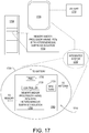
- FIG. 17 illustrates a mobile computing platform and a data server machine employing an SoC including a transistor with localized sub-fin isolation, in accordance with embodiments of the present invention.
- the server machine 1706 may be any commercial server, for example including any number of high-performance computing platforms disposed within a rack and networked together for electronic data processing, which in the exemplary embodiment includes a packaged monolithic SoC 1750.
- the mobile computing platform 1705 may be any portable device configured for each of electronic data display, electronic data processing, wireless electronic data transmission, or the like.
- the mobile computing platform 1705 may be any of a tablet, a smart phone, laptop computer, etc., and may include a display screen (e.g., a capacitive, inductive, resistive, or optical touchscreen), a chip-level or package-level integrated system 1710, and a battery 1715.
- a display screen e.g., a capacitive, inductive, resistive, or optical touchscreen
- a chip-level or package-level integrated system 1710 e.g., a battery 1715.
- packaged monolithic SoC 1750 includes a memory block (e.g., RAM), a processor block (e.g., a microprocessor, a multi-core microprocessor, graphics processor, or the like) including at least one non-silicon channeled FET (e.g., a III-V channeled FET) with a channel region disposed over a localized isolation material, for example as describe elsewhere herein.
- a memory block e.g., RAM
- processor block e.g., a microprocessor, a multi-core microprocessor, graphics processor, or the like
- non-silicon channeled FET e.g., a III-V channeled FET
- the monolithic SoC 1750 may be further coupled to a board, a substrate, or an interposer 1760 along with, one or more of a power management integrated circuit (PMIC) 1730, RF (wireless) integrated circuit (RFIC) 1725 including a wideband RF (wireless) transmitter and/or receiver (TX/RX) (e.g., including a digital baseband and an analog front end module further comprises a power amplifier on a transmit path and a low noise amplifier on a receive path), and a controller 1735.
- PMIC power management integrated circuit
- RFIC wireless) integrated circuit
- TX/RX wideband RF (wireless) transmitter and/or receiver
- PMIC 1730 may perform battery power regulation, DC-to-DC conversion, etc., and so has an input coupled to battery 1715 and with an output providing a current supply to other functional modules.
- RFIC 1725 has an output coupled to an antenna (not shown) to implement any of a number of wireless standards or protocols, including but not limited to Wi-Fi (IEEE 802.11 family), WiMAX (IEEE 802.16 family), IEEE 802.20, long term evolution (LTE), Ev-DO, HSPA+, HSDPA+, HSUPA+, EDGE, GSM, GPRS, CDMA, TDMA, DECT, Bluetooth, derivatives thereof, as well as any other wireless protocols that are designated as 3G, 4G, 5G, and beyond.
- each of these board-level modules may be integrated onto separate ICs or integrated into monolithic SoC 1750.
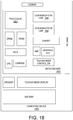
- FIG. 18 is a functional block diagram of an electronic computing device, in accordance with an embodiment of the present invention.
- Computing device 1800 may be found inside platform 1705 or server machine 1706, for example.
- Device 1800 further includes a motherboard 1802 hosting a number of components, such as, but not limited to, a processor 1804 (e.g., an applications processor), which may further incorporate at least one non-silicon (e.g., III-V) channeled FET disposed over a localized isolation material, in accordance with embodiments of the present invention.
- Processor 1804 may be physically and/or electrically coupled to motherboard 1802.
- processor 1804 includes an integrated circuit die packaged within the processor 1804.
- the term "processor” or "microprocessor” may refer to any device or portion of a device that processes electronic data from registers and/or memory to transform that electronic data into other electronic data that may be further stored in registers and/or memory.
- one or more communication chips 1806 may also be physically and/or electrically coupled to the motherboard 1802. In further implementations, communication chips 1806 may be part of processor 1804. Depending on its applications, computing device 1800 may include other components that may or may not be physically and electrically coupled to motherboard 1802.
- volatile memory e.g., DRAM
- non-volatile memory e.g., ROM
- flash memory e.g., a graphics processor, a digital signal processor, a crypto processor, a chipset, an antenna, touchscreen display, touchscreen controller, battery, audio codec, video codec, power amplifier, global positioning system (GPS) device, compass, accelerometer, gyroscope, speaker, camera, and mass storage device (such as hard disk drive, solid-state drive (SSD), compact disk (CD), digital versatile disk (DVD), and so forth), or the like.
- volatile memory e.g., DRAM
- non-volatile memory e.g., ROM
- flash memory e.g., a graphics processor, a digital signal processor, a crypto processor, a chipset, an antenna, touchscreen display, touchscreen controller, battery, audio codec, video codec, power amplifier, global positioning system (GPS) device, compass, accelerometer, gyroscope, speaker, camera
- Communication chips 1806 may enable wireless communications for the transfer of data to and from the computing device 1800.
- the term "wireless” and its derivatives may be used to describe circuits, devices, systems, methods, techniques, communications channels, etc., that may communicate data through the use of modulated electromagnetic radiation through a non-solid medium. The term does not imply that the associated devices do not contain any wires, although in some embodiments they might not.
- Communication chips 1806 may implement any of a number of wireless standards or protocols, including but not limited to those described elsewhere herein. As discussed, computing device 1800 may include a plurality of communication chips 1806.
- a first communication chip may be dedicated to shorter-range wireless communications, such as Wi-Fi and Bluetooth, and a second communication chip may be dedicated to longer-range wireless communications such as GPS, EDGE, GPRS, CDMA, WiMAX, LTE, Ev-DO, and others.
- a field effect transistor comprises a sub-fin structure comprising a first crystalline material disposed over a substrate of a second crystalline material, and an amorphous sub-fin isolation material extending through at least a portion of the crystalline material.
- the FET further comprises a fin structure comprising a third crystalline material and including a pair of source/drain ends on opposite sides of a channel region, the fin structure extending from the sub-fin structure with the channel region separated from the first crystalline material by the sub-fin isolation material.
- the FET further comprises a gate electrode stack disposed over the channel, and a pair of source/drain contacts coupled to the pair of source/drain ends of the fin structure.
- the sub-fin isolation material has a lateral dimension parallel to a source-drain length of the fin structure that is larger than a length of the channel region over which the gate electrode stack is disposed.
- the sub-fin isolation material occupies a recess in the sub-fin defined by one or more crystallographic facets in the first crystalline material.
- the sub-fin structure comprises a fin of the first crystalline material disposed on a surface of the substrate and surrounded by a dielectric trench material disposed over the substrate.
- the sub-fin isolation material has a first lateral dimension orthogonal to a longest length of the fin that is equal to a width of the fin and a second lateral dimension parallel to the longest length of the fin that is at least equal to a length of the gate electrode stack disposed over the channel region.
- the sub-fin structure comprises a fin of the first crystalline material disposed on a surface of the substrate and surrounded by a dielectric trench material disposed over the substrate.
- the sub-fin isolation material has a first lateral dimension orthogonal to a longest length of the fin that is greater than a width of the fin with a portion of the sub-fin isolation material extending beyond both opposite sidewalls of the fin embedded within the trench material.
- the gate electrode stack has a second lateral dimension orthogonal to the longest length of the fin structure that is greater than the width of the fin structure with a portion of the gate electrode stack disposed over the sub-fin isolation material.
- the first and second lateral dimensions are equal with edges of the portion of the gate electrode stack disposed over the sub-fin isolation material aligned with edges of the sub-fin isolation material interfacing with the trench material.
- the sub-fin isolation material has a greater thickness within a region below the fin than in a region extending beyond sidewalls of the fin.
- the sub-fin isolation material further comprises the gate dielectric material in contact with the third crystalline material.
- the fin structure further comprises a fourth crystalline material disposed between the third and first crystalline materials.
- the fourth crystalline material is in contact with the first crystalline material at the source/drain ends and in contact with the sub-fin isolation material at the channel region.
- the first crystalline material is a first III-V material
- the second crystalline material is silicon
- the third crystalline material is a second III-V material.
- the sub-fin structure comprises a fin of the first crystalline material disposed on a surface of the substrate silicon and disposed within a trench extending through a dielectric trench material disposed over the substrate silicon.
- the sub-fin isolation material is embedded within the trench material.
- the transistor further comprises a raised doped source/drain material in contact with the contact metallization and disposed on one or more sidewalls of the fin structure at the source/drain ends.
- the first crystalline material comprises a first of GaAs, InP, InAs, InGaAs, AlGaAs, GaP, AlAs, or InGaP
- the second crystalline material is Si
- the third crystalline material comprises a second of GaAs, InP, InAs, InGaAs, AlGaAs, GaP, AlAs, or InGaP
- the sub-fin isolation material is a dielectric selected from the group consisting of a metal oxide, a silicon oxide, and an polymer dielectric.
- a microelectronic device comprises a plurality of crystalline sub-fin structures disposed over a crystalline silicon substrate, each sub-fin structure comprising a fin of a first III-V material.
- the microelectronic device comprises a plurality of crystalline fin structures aligned with the sub-fin structures, each fin structure comprising a second III-V material and including a pair of source/drain ends on opposite sides of a channel region, wherein the second III-V material of one fin structure is in contact with the first III-V material of one sub-fin structure at the source/drain ends.
- the microelectronic device comprises an amorphous sub-fin isolation material stripe intersecting the plurality of sub-fin structures and fin structures, wherein the sub-fin isolation material stripe separates the second III-V material of each fin structure from the first III-V material at the channel regions.
- the microelectronic device further comprises a gate electrode stack stripe disposed over, and aligned with, the sub-fin isolation material stripe, wherein the gate electrode stack comprises at least a gate dielectric material and an overlying gate metal, and wherein the gate electrode stack stripe is disposed over the channel region and in contact with at least two sidewalls of each of the fin structures.
- the microelectronic device further comprises source/drain metallization disposed on opposite sides of the gate electrode stack stripe and coupled to one or more of the source/drain ends.
- sub-fin isolation material stripe contacts the silicon substrate within a region where the sub-fin isolation material stripe intersects the fin structure, the sub-fin isolation material stripe separating pairs of the plurality of crystalline sub-fin structures.
- the fin structure further comprises a third III-V material disposed over the second III-V material, and the gate electrode stack is in contact with at least two sidewalls of third III-V material with the channel region.
- a method of forming a field effect transistor comprises receiving a crystalline fin comprising a first III-V material disposed on a crystalline sub-fin comprising a second III-V material.
- the method comprises removing a width of the sub-fin to undercut the fin within a channel region of the fin.
- the method comprises backfilling the undercut fin channel region with a sub-fin isolation material.
- the method comprises forming a gate stack over the channel region of the fin.
- the method comprises forming contact metallization coupled to source/drain ends of the fin.
- the method further comprises forming a trench in a trench material, the trench exposing a crystalline substrate surface, heteroepitaxially growing the crystalline sub-fin on an exposed substrate surface within the trench, and heteroepitaxially growing the crystalline fin on a sub-fin surface within the trench.
- removing a width of the sub-fin to undercut the fin within a channel region of the fin further comprises forming a gate stack mandrel over the channel region of the fin and a mask material over the source/drain ends of the fin, removing the gate stack mandrel while retaining the mask material, and isotropically etching the sub-fin while the source/drain ends are protected by the mask material.
- forming the gate stack mandrel further comprises depositing a mandrel material over a sidewall of both the fin and at least a portion of a sidewall of the sub-fin.
- isotropically etching the sub-fin further comprises forming etch facets in the sub-fin by exposing the sub-fin to a crystallographic etchant.
- backfilling the undercut fin channel region with the sub-fin isolation material further comprises at least one of spinning on a polymer dielectric, depositing a metal oxide with an atomic layer deposition process, or depositing a silicon oxide with a chemical vapor deposition and reflow process.
- forming the gate stack over the channel region of the fin further comprises planarizing the sub-fin isolation material, recessing the sub-fin isolation material to expose sidewalls of the fin while the source/drain ends are protected by the mask material, depositing the gate dielectric material and the gate metal over the recessed sub-fin isolation material and over the exposed fin sidewalls, and planarizing the gate metal with the mask material.
Landscapes
- Insulated Gate Type Field-Effect Transistor (AREA)
- Chemical & Material Sciences (AREA)
- Engineering & Computer Science (AREA)
- Materials Engineering (AREA)
- Thin Film Transistor (AREA)
Claims (15)
- Transistor à effet de champ (FET), comprenant :une structure de sous-ailette comprenant un premier matériau cristallin (110) disposé par-dessus un substrat (105) d'un deuxième matériau cristallin, et un matériau d'isolation de sous-ailette amorphe (130) s'étendant à travers au moins une partie du premier matériau cristallin (110) ;une structure d'ailette (103) comprenant un troisième matériau cristallin (120) et comportant une paire d'extrémités de source/drain sur des côtés opposés d'une région de canal (205), la structure d'ailette (103) s'étendant depuis la structure de sous-ailette avec la région de canal (205) séparée du premier matériau cristallin (110) par le matériau d'isolation de sous-ailette (130),dans lequel le premier matériau cristallin (110) est un premier matériau III-V ;dans lequel le deuxième matériau cristallin (105) est du silicium ; etdans lequel le troisième matériau cristallin (120) est un second matériau III-V, l'interface entre le premier matériau cristallin et le troisième matériau cristallin étant une hétérojonction ;un empilement d'électrode grille (170) disposé par-dessus la région de canal (205) ; etune paire de contacts de source/drain (150) couplée à la paire d'extrémités de source/drain de la structure d'ailette.
- Transistor selon la revendication 1, dans lequel le matériau d'isolation de sous-ailette (130) présente une dimension latérale (L1) parallèle à la longueur source-drain de la structure d'ailette supérieure à une longueur (L2) de la région de canal par-dessus laquelle est disposé l'empilement d'électrode grille (170).
- Transistor selon la revendication 2, dans lequel le matériau d'isolation de sous-ailette (130) occupe un renfoncement dans la structure de sous-ailette défini par une ou plusieurs facettes cristallographiques dans le premier matériau cristallin.
- Transistor selon la revendication l, dans lequel :la structure de sous-ailette comprend une ailette du premier matériau cristallin (110) disposée sur une surface du substrat (105) et entourée par un matériau de tranchée diélectrique (115) disposé par-dessus le substrat (105) ; etle matériau d'isolation de sous-ailette (130) présente une première dimension latérale (W2) orthogonale à une plus longue longueur de l'ailette qui est égale à une largeur de l'ailette (W1) et une seconde dimension latérale (L1) parallèle à la plus longue longueur de l'ailette qui est au moins égale à une longueur (L2) de l'empilement d'électrode grille disposé par-dessus la région de canal.
- Transistor selon la revendication 1, dans lequel :la structure de sous-ailette comprend une ailette du premier matériau cristallin (110) disposée sur une surface du substrat et entourée par un matériau de tranchée diélectrique (115) disposé par-dessus le substrat ;le matériau d'isolation de sous-ailette (130) présente une première dimension latérale (W2) orthogonale à une plus longue longueur de l'ailette qui est supérieure à une largeur (W1) de l'ailette avec une partie du matériau d'isolation de sous-ailette (130) s'étendant au-delà des deux parois latérales opposées de l'ailette noyées dans le matériau de tranchée (115) ;l'empilement d'électrode grille (170) présente une seconde dimension latérale orthogonale à la plus longue longueur de la structure d'ailette qui est supérieure à la largeur de la structure d'ailette avec une partie de l'empilement d'électrode grille disposé par-dessus le matériau d'isolation de sous-ailette ; etles première et seconde dimensions latérales sont égales avec des bords de la partie de l'empilement d'électrode grille disposé par-dessus le matériau d'isolation de sous-ailette alignés avec des bords du matériau d'isolation de sous-ailette s'interfaçant avec le matériau de tranchée.
- Transistor selon la revendication 5, dans lequel le matériau d'isolation de sous-ailette (130) présente une épaisseur plus importante dans une région en-dessous de l'ailette que dans une région s'étendant au-delà de parois latérales de l'ailette.
- Transistor selon la revendication 1, dans lequel le matériau d'isolation de sous-ailette (130) comprend en outre un matériau diélectrique de grille (172) en contact avec le troisième matériau cristallin (120).
- Transistor selon la revendication l, dans lequel :la structure d'ailette comprend en outre un quatrième matériau cristallin (380) disposé entre les troisième (120) et premier (110) matériaux cristallins, le quatrième matériau cristallin (380) présentant une bande de porteurs décalée de celle du premier matériau cristallin ;dans lequel le quatrième matériau cristallin (380) est en contact avec le premier matériau cristallin (110) au niveau des extrémités de source/drain et en contact avec le matériau d'isolation de sous-ailette (130) au niveau de la région de canal (205).
- Transistor selon la revendication 1, dans lequel :la structure de sous-ailette (110) comprend une ailette du premier matériau cristallin disposée sur une surface du substrat semi-conducteur (105) et disposée au sein d'une tranchée s'étendant à travers un matériau de tranchée diélectrique disposé par-dessus le substrat à semi-conducteur (105) ; etle matériau d'isolation de sous-ailette est noyé au sein du matériau de tranchée.
- Transistor selon la revendication l, comprenant en outre un matériau de source/drain dopé surélevé (140) en contact avec la métallisation de contact (150) et disposé sur une ou plusieurs parois latérales de la structure d'ailette au niveau des extrémités de source/drain.
- Transistor selon la revendication l, dans lequel :le premier matériau cristallin (110) comprend un premier GaAs, InP, InAs, InGaAs, AlGaAs, GaP, AlAs, ou InGaP ;le troisième matériau cristallin (120) comprend un second GaAs, InP, InAs, InGaAs, AlGaAs, GaP, AlAs, ou InGaP ; etle matériau d'isolation de sous-ailette (130) est un diélectrique sélectionné dans le groupe consistant en un oxyde métallique, un oxyde de silicium, et un diélectrique polymère.
- Dispositif micro-électronique (101, 102), comprenant:une pluralité de structures de sous-ailettes cristallines disposée par-dessus un substrat de silicium cristallin (105), chaque structure de sous-ailette comprenant une ailette d'un premier matériau III-V (110) ;une pluralité de structures d'ailettes cristallines alignées avec les structures de sous-ailettes, chaque structure d'ailette comprenant un second matériau III-V (120) et comportant une paire d'extrémités de source/drain sur des côtés opposés d'une région de canal (205), dans lequel le second matériau III-V (120) d'une structure d'ailette est en contact avec le premier matériau III-V (110) d'une structure de sous-ailette au niveau des extrémités de source/drain, et une interface entre le premier matériau III-V (110) et le second matériau III-V (120) étant une hétérojonction ;un bande de matériau d'isolation de sous-ailette amorphe (130) entrecoupant la pluralité de structures de sous-ailettes et de structures d'ailettes, la bande de matériau d'isolation de sous-ailette (130) séparant le second matériau III-V (120) de chaque structure d'ailette du premier matériau III-V (110) au niveau des régions de canal ;une bande d'empilement d'électrode grille (170) disposée par-dessus la bande de matériau d'isolation de sous-ailette (130) et alignée avec celle-ci, la bande d'empilement d'électrode grille (170) comprenant au moins un matériau diélectrique de grille (172) et un métal de grille de recouvrement (173), et la bande d'empilement d'électrode grille étant disposée par-dessus la région de canal (205) et en contact avec au moins deux parois latérales de chacune des structures d'ailettes ; etune métallisation de source/drain (150) disposée sur des côtés opposés de la bande d'empilement d'électrode grille et couplée à une ou plusieurs des extrémités de source/drain.
- Dispositif selon la revendication 12, dans lequel une bande de matériau d'isolation de sous-ailette (130) fait contact avec le substrat de silicium (105) dans une région où la bande de matériau d'isolation de sous-ailette entrecoupe la structure d'ailette, la bande de matériau d'isolation de sous-ailette séparant des paires de la pluralité de structures de sous-ailettes cristallines.
- Procédé (401) de formation d'un transistor à effet de champ, le procédé comprenant :la réception (420, 430) d'une ailette cristalline comprenant un premier matériau III-V disposée sur une sous-ailette cristalline comprenant un second matériau III-V, une interface entre le premier matériau III-V et le second matériau III-V étant une hétérojonction ;l'élimination (460) d'une largeur de la sous-ailette pour contre-dépouiller l'ailette dans une région de canal de l'ailette ;le remblayage (470) de la région de canal d'ailette contre-dépouillée avec un matériau d'isolation de sous-ailette amorphe ;la formation (480) d'un empilement de grille par-dessus la région de canal de l'ailette ; etla formation (490) d'une métallisation de contact couplée aux extrémités de source/drain de l'ailette.
- Procédé selon la revendication 14, comprenant en outre :la formation (410) d'une tranchée dans un matériau de tranchée, la tranchée exposant une surface de substrat cristallin ;la croissance hétéroépitaxiale (420) de la sous-ailette cristalline sur une surface de substrat exposée au sein de la tranchée ; etla croissance hétéroépitaxiale (430) de l'ailette cristalline sur une surface de sous-ailette au sein de la tranchée.
Applications Claiming Priority (1)
| Application Number | Priority Date | Filing Date | Title |
|---|---|---|---|
| PCT/US2015/038069 WO2016209278A1 (fr) | 2015-06-26 | 2015-06-26 | Transistors à haute mobilité d'électrons avec isolation sous-ailette localisée |
Publications (3)
| Publication Number | Publication Date |
|---|---|
| EP3314663A1 EP3314663A1 (fr) | 2018-05-02 |
| EP3314663A4 EP3314663A4 (fr) | 2019-02-20 |
| EP3314663B1 true EP3314663B1 (fr) | 2020-12-16 |
Family
ID=57586438
Family Applications (1)
| Application Number | Title | Priority Date | Filing Date |
|---|---|---|---|
| EP15896564.0A Active EP3314663B1 (fr) | 2015-06-26 | 2015-06-26 | Transistors à haute mobilité d'électrons avec isolation sous-ailette localisée |
Country Status (6)
| Country | Link |
|---|---|
| US (1) | US10431690B2 (fr) |
| EP (1) | EP3314663B1 (fr) |
| KR (1) | KR102358303B1 (fr) |
| CN (1) | CN107636837B (fr) |
| TW (1) | TW201712873A (fr) |
| WO (1) | WO2016209278A1 (fr) |
Families Citing this family (14)
| Publication number | Priority date | Publication date | Assignee | Title |
|---|---|---|---|---|
| CN108258033B (zh) * | 2016-12-29 | 2020-12-22 | 中芯国际集成电路制造(上海)有限公司 | 半导体器件及其形成方法 |
| CN108987476B (zh) * | 2017-06-01 | 2021-05-11 | 中芯国际集成电路制造(上海)有限公司 | 半导体结构及其形成方法 |
| US10510840B2 (en) | 2017-06-20 | 2019-12-17 | Taiwan Semiconductor Manufacturing Co., Ltd. | GAA FET with u-shaped channel |
| US10867866B2 (en) * | 2017-10-30 | 2020-12-15 | Taiwan Semiconductor Manufacturing Co., Ltd. | Semiconductor device and manufacturing method thereof |
| US11557658B2 (en) * | 2017-12-27 | 2023-01-17 | Intel Corporation | Transistors with high density channel semiconductor over dielectric material |
| WO2019139626A1 (fr) * | 2018-01-12 | 2019-07-18 | Intel Corporation | Dispositif semi-conducteur non plan comprenant une structure de canal de remplacement |
| US10727352B2 (en) * | 2018-01-26 | 2020-07-28 | International Business Machines Corporation | Long-channel fin field effect transistors |
| WO2019164509A1 (fr) * | 2018-02-23 | 2019-08-29 | Intel Corporation | Mise en forme d'ailette à l'aide de modèles et structures de circuit intégré résultant de celle-ci |
| WO2019168541A1 (fr) * | 2018-03-02 | 2019-09-06 | Intel Corporation | Transistors empilés de type n et de type p sans silicium pour dispositifs à circuits intégrés |
| US11127747B2 (en) * | 2019-08-23 | 2021-09-21 | Micron Technology, Inc. | Transistors including two-dimensional materials |
| EP3913655A1 (fr) | 2020-05-18 | 2021-11-24 | IMEC vzw | Intégration d'une construction iii-v sur un substrat de groupe iv |
| US11462632B2 (en) | 2020-12-22 | 2022-10-04 | Globalfoundries U.S. Inc. | Lateral bipolar junction transistor device and method of making such a device |
| US11424349B1 (en) | 2021-02-17 | 2022-08-23 | Globalfoundries U.S. Inc. | Extended shallow trench isolation for ultra-low leakage in fin-type lateral bipolar junction transistor devices |
| KR20220166971A (ko) | 2021-06-11 | 2022-12-20 | 삼성전자주식회사 | 반도체 집적회로 소자 및 이의 제조 방법 |
Family Cites Families (16)
| Publication number | Priority date | Publication date | Assignee | Title |
|---|---|---|---|---|
| KR100712543B1 (ko) * | 2005-12-31 | 2007-04-30 | 삼성전자주식회사 | 다중채널을 갖는 반도체소자 및 그 제조방법 |
| US20090206405A1 (en) * | 2008-02-15 | 2009-08-20 | Doyle Brian S | Fin field effect transistor structures having two dielectric thicknesses |
| US8912602B2 (en) | 2009-04-14 | 2014-12-16 | Taiwan Semiconductor Manufacturing Company, Ltd. | FinFETs and methods for forming the same |
| US8471344B2 (en) | 2009-09-21 | 2013-06-25 | International Business Machines Corporation | Integrated circuit device with series-connected fin-type field effect transistors and integrated voltage equalization and method of forming the device |
| CN102117829B (zh) * | 2009-12-30 | 2012-11-21 | 中国科学院微电子研究所 | 鳍式晶体管结构及其制作方法 |
| CN102543668B (zh) * | 2010-12-08 | 2014-05-07 | 中国科学院微电子研究所 | 悬空鳍片的制备方法 |
| US8492235B2 (en) * | 2010-12-29 | 2013-07-23 | Globalfoundries Singapore Pte. Ltd. | FinFET with stressors |
| CN102651321B (zh) * | 2011-02-25 | 2015-03-04 | 中国科学院微电子研究所 | 一种半导体器件的制备方法 |
| US8779554B2 (en) * | 2012-03-30 | 2014-07-15 | Taiwan Semiconductor Manufacturing Company, Ltd. | MOSFETs with channels on nothing and methods for forming the same |
| CN103855011B (zh) * | 2012-11-30 | 2017-10-17 | 中国科学院微电子研究所 | FinFET及其制造方法 |
| US8759874B1 (en) * | 2012-11-30 | 2014-06-24 | Stmicroelectronics, Inc. | FinFET device with isolated channel |
| US8956942B2 (en) * | 2012-12-21 | 2015-02-17 | Stmicroelectronics, Inc. | Method of forming a fully substrate-isolated FinFET transistor |
| US8896101B2 (en) * | 2012-12-21 | 2014-11-25 | Intel Corporation | Nonplanar III-N transistors with compositionally graded semiconductor channels |
| US9000522B2 (en) | 2013-01-09 | 2015-04-07 | International Business Machines Corporation | FinFET with dielectric isolation by silicon-on-nothing and method of fabrication |
| US9735255B2 (en) * | 2013-01-18 | 2017-08-15 | Taiwan Semiconductor Manufacturing Company, Ltd. | Method for fabricating a finFET device including a stem region of a fin element |
| US9786765B2 (en) * | 2016-02-16 | 2017-10-10 | Globalfoundries Inc. | FINFET having notched fins and method of forming same |
-
2015
- 2015-06-26 KR KR1020187002245A patent/KR102358303B1/ko active Active
- 2015-06-26 US US15/575,111 patent/US10431690B2/en active Active
- 2015-06-26 CN CN201580080351.0A patent/CN107636837B/zh active Active
- 2015-06-26 EP EP15896564.0A patent/EP3314663B1/fr active Active
- 2015-06-26 WO PCT/US2015/038069 patent/WO2016209278A1/fr not_active Ceased
-
2016
- 2016-05-19 TW TW105115538A patent/TW201712873A/zh unknown
Non-Patent Citations (1)
| Title |
|---|
| None * |
Also Published As
| Publication number | Publication date |
|---|---|
| US20180158957A1 (en) | 2018-06-07 |
| EP3314663A1 (fr) | 2018-05-02 |
| KR102358303B1 (ko) | 2022-02-07 |
| TW201712873A (en) | 2017-04-01 |
| EP3314663A4 (fr) | 2019-02-20 |
| WO2016209278A1 (fr) | 2016-12-29 |
| CN107636837A (zh) | 2018-01-26 |
| US10431690B2 (en) | 2019-10-01 |
| CN107636837B (zh) | 2021-11-30 |
| KR20180020288A (ko) | 2018-02-27 |
Similar Documents
| Publication | Publication Date | Title |
|---|---|---|
| EP3314663B1 (fr) | Transistors à haute mobilité d'électrons avec isolation sous-ailette localisée | |
| US11417655B2 (en) | High-mobility semiconductor source/drain spacer | |
| US10665708B2 (en) | Semiconductor devices with raised doped crystalline structures | |
| US10453679B2 (en) | Methods and devices integrating III-N transistor circuitry with Si transistor circuitry | |
| US10411007B2 (en) | High mobility field effect transistors with a band-offset semiconductor source/drain spacer | |
| US10461082B2 (en) | Well-based integration of heteroepitaxial N-type transistors with P-type transistors | |
| US20190096917A1 (en) | Semiconductor diodes employing back-side seimconductor or metal | |
| WO2017052619A1 (fr) | Transistors à effet de champ à mobilité élevée dotés d'une source et d'un drain de semi-conducteur rétrogradés | |
| US11996447B2 (en) | Field effect transistors with gate electrode self-aligned to semiconductor fin | |
| US10546858B2 (en) | Low damage self-aligned amphoteric FINFET tip doping | |
| WO2017003414A1 (fr) | Dopage amphotère auto-aligné à faible endommagement de pointe de finfet |
Legal Events
| Date | Code | Title | Description |
|---|---|---|---|
| STAA | Information on the status of an ep patent application or granted ep patent |
Free format text: STATUS: THE INTERNATIONAL PUBLICATION HAS BEEN MADE |
|
| PUAI | Public reference made under article 153(3) epc to a published international application that has entered the european phase |
Free format text: ORIGINAL CODE: 0009012 |
|
| STAA | Information on the status of an ep patent application or granted ep patent |
Free format text: STATUS: REQUEST FOR EXAMINATION WAS MADE |
|
| 17P | Request for examination filed |
Effective date: 20171121 |
|
| AK | Designated contracting states |
Kind code of ref document: A1 Designated state(s): AL AT BE BG CH CY CZ DE DK EE ES FI FR GB GR HR HU IE IS IT LI LT LU LV MC MK MT NL NO PL PT RO RS SE SI SK SM TR |
|
| AX | Request for extension of the european patent |
Extension state: BA ME |
|
| DAV | Request for validation of the european patent (deleted) | ||
| DAX | Request for extension of the european patent (deleted) | ||
| A4 | Supplementary search report drawn up and despatched |
Effective date: 20190122 |
|
| RIC1 | Information provided on ipc code assigned before grant |
Ipc: H01L 29/78 20060101AFI20190117BHEP Ipc: H01L 29/66 20060101ALI20190117BHEP |
|
| RIC1 | Information provided on ipc code assigned before grant |
Ipc: H01L 29/78 20060101AFI20200525BHEP Ipc: H01L 29/06 20060101ALI20200525BHEP Ipc: H01L 29/66 20060101ALI20200525BHEP |
|
| GRAP | Despatch of communication of intention to grant a patent |
Free format text: ORIGINAL CODE: EPIDOSNIGR1 |
|
| STAA | Information on the status of an ep patent application or granted ep patent |
Free format text: STATUS: GRANT OF PATENT IS INTENDED |
|
| INTG | Intention to grant announced |
Effective date: 20200707 |
|
| GRAS | Grant fee paid |
Free format text: ORIGINAL CODE: EPIDOSNIGR3 |
|
| GRAA | (expected) grant |
Free format text: ORIGINAL CODE: 0009210 |
|
| STAA | Information on the status of an ep patent application or granted ep patent |
Free format text: STATUS: THE PATENT HAS BEEN GRANTED |
|
| AK | Designated contracting states |
Kind code of ref document: B1 Designated state(s): AL AT BE BG CH CY CZ DE DK EE ES FI FR GB GR HR HU IE IS IT LI LT LU LV MC MK MT NL NO PL PT RO RS SE SI SK SM TR |
|
| REG | Reference to a national code |
Ref country code: GB Ref legal event code: FG4D |
|
| REG | Reference to a national code |
Ref country code: IE Ref legal event code: FG4D |
|
| REG | Reference to a national code |
Ref country code: DE Ref legal event code: R096 Ref document number: 602015063708 Country of ref document: DE |
|
| REG | Reference to a national code |
Ref country code: AT Ref legal event code: REF Ref document number: 1346367 Country of ref document: AT Kind code of ref document: T Effective date: 20210115 |
|
| PG25 | Lapsed in a contracting state [announced via postgrant information from national office to epo] |
Ref country code: GR Free format text: LAPSE BECAUSE OF FAILURE TO SUBMIT A TRANSLATION OF THE DESCRIPTION OR TO PAY THE FEE WITHIN THE PRESCRIBED TIME-LIMIT Effective date: 20210317 Ref country code: FI Free format text: LAPSE BECAUSE OF FAILURE TO SUBMIT A TRANSLATION OF THE DESCRIPTION OR TO PAY THE FEE WITHIN THE PRESCRIBED TIME-LIMIT Effective date: 20201216 Ref country code: RS Free format text: LAPSE BECAUSE OF FAILURE TO SUBMIT A TRANSLATION OF THE DESCRIPTION OR TO PAY THE FEE WITHIN THE PRESCRIBED TIME-LIMIT Effective date: 20201216 Ref country code: NO Free format text: LAPSE BECAUSE OF FAILURE TO SUBMIT A TRANSLATION OF THE DESCRIPTION OR TO PAY THE FEE WITHIN THE PRESCRIBED TIME-LIMIT Effective date: 20210316 |
|
| REG | Reference to a national code |
Ref country code: AT Ref legal event code: MK05 Ref document number: 1346367 Country of ref document: AT Kind code of ref document: T Effective date: 20201216 |
|
| REG | Reference to a national code |
Ref country code: NL Ref legal event code: MP Effective date: 20201216 |
|
| PG25 | Lapsed in a contracting state [announced via postgrant information from national office to epo] |
Ref country code: BG Free format text: LAPSE BECAUSE OF FAILURE TO SUBMIT A TRANSLATION OF THE DESCRIPTION OR TO PAY THE FEE WITHIN THE PRESCRIBED TIME-LIMIT Effective date: 20210316 Ref country code: LV Free format text: LAPSE BECAUSE OF FAILURE TO SUBMIT A TRANSLATION OF THE DESCRIPTION OR TO PAY THE FEE WITHIN THE PRESCRIBED TIME-LIMIT Effective date: 20201216 Ref country code: SE Free format text: LAPSE BECAUSE OF FAILURE TO SUBMIT A TRANSLATION OF THE DESCRIPTION OR TO PAY THE FEE WITHIN THE PRESCRIBED TIME-LIMIT Effective date: 20201216 |
|
| PG25 | Lapsed in a contracting state [announced via postgrant information from national office to epo] |
Ref country code: NL Free format text: LAPSE BECAUSE OF FAILURE TO SUBMIT A TRANSLATION OF THE DESCRIPTION OR TO PAY THE FEE WITHIN THE PRESCRIBED TIME-LIMIT Effective date: 20201216 Ref country code: HR Free format text: LAPSE BECAUSE OF FAILURE TO SUBMIT A TRANSLATION OF THE DESCRIPTION OR TO PAY THE FEE WITHIN THE PRESCRIBED TIME-LIMIT Effective date: 20201216 |
|
| REG | Reference to a national code |
Ref country code: LT Ref legal event code: MG9D |
|
| PG25 | Lapsed in a contracting state [announced via postgrant information from national office to epo] |
Ref country code: EE Free format text: LAPSE BECAUSE OF FAILURE TO SUBMIT A TRANSLATION OF THE DESCRIPTION OR TO PAY THE FEE WITHIN THE PRESCRIBED TIME-LIMIT Effective date: 20201216 Ref country code: CZ Free format text: LAPSE BECAUSE OF FAILURE TO SUBMIT A TRANSLATION OF THE DESCRIPTION OR TO PAY THE FEE WITHIN THE PRESCRIBED TIME-LIMIT Effective date: 20201216 Ref country code: SM Free format text: LAPSE BECAUSE OF FAILURE TO SUBMIT A TRANSLATION OF THE DESCRIPTION OR TO PAY THE FEE WITHIN THE PRESCRIBED TIME-LIMIT Effective date: 20201216 Ref country code: LT Free format text: LAPSE BECAUSE OF FAILURE TO SUBMIT A TRANSLATION OF THE DESCRIPTION OR TO PAY THE FEE WITHIN THE PRESCRIBED TIME-LIMIT Effective date: 20201216 Ref country code: PT Free format text: LAPSE BECAUSE OF FAILURE TO SUBMIT A TRANSLATION OF THE DESCRIPTION OR TO PAY THE FEE WITHIN THE PRESCRIBED TIME-LIMIT Effective date: 20210416 Ref country code: SK Free format text: LAPSE BECAUSE OF FAILURE TO SUBMIT A TRANSLATION OF THE DESCRIPTION OR TO PAY THE FEE WITHIN THE PRESCRIBED TIME-LIMIT Effective date: 20201216 Ref country code: RO Free format text: LAPSE BECAUSE OF FAILURE TO SUBMIT A TRANSLATION OF THE DESCRIPTION OR TO PAY THE FEE WITHIN THE PRESCRIBED TIME-LIMIT Effective date: 20201216 |
|
| PG25 | Lapsed in a contracting state [announced via postgrant information from national office to epo] |
Ref country code: AT Free format text: LAPSE BECAUSE OF FAILURE TO SUBMIT A TRANSLATION OF THE DESCRIPTION OR TO PAY THE FEE WITHIN THE PRESCRIBED TIME-LIMIT Effective date: 20201216 Ref country code: PL Free format text: LAPSE BECAUSE OF FAILURE TO SUBMIT A TRANSLATION OF THE DESCRIPTION OR TO PAY THE FEE WITHIN THE PRESCRIBED TIME-LIMIT Effective date: 20201216 |
|
| REG | Reference to a national code |
Ref country code: DE Ref legal event code: R097 Ref document number: 602015063708 Country of ref document: DE |
|
| PG25 | Lapsed in a contracting state [announced via postgrant information from national office to epo] |
Ref country code: IS Free format text: LAPSE BECAUSE OF FAILURE TO SUBMIT A TRANSLATION OF THE DESCRIPTION OR TO PAY THE FEE WITHIN THE PRESCRIBED TIME-LIMIT Effective date: 20210416 |
|
| PLBE | No opposition filed within time limit |
Free format text: ORIGINAL CODE: 0009261 |
|
| STAA | Information on the status of an ep patent application or granted ep patent |
Free format text: STATUS: NO OPPOSITION FILED WITHIN TIME LIMIT |
|
| PG25 | Lapsed in a contracting state [announced via postgrant information from national office to epo] |
Ref country code: IT Free format text: LAPSE BECAUSE OF FAILURE TO SUBMIT A TRANSLATION OF THE DESCRIPTION OR TO PAY THE FEE WITHIN THE PRESCRIBED TIME-LIMIT Effective date: 20201216 Ref country code: AL Free format text: LAPSE BECAUSE OF FAILURE TO SUBMIT A TRANSLATION OF THE DESCRIPTION OR TO PAY THE FEE WITHIN THE PRESCRIBED TIME-LIMIT Effective date: 20201216 |
|
| 26N | No opposition filed |
Effective date: 20210917 |
|
| PG25 | Lapsed in a contracting state [announced via postgrant information from national office to epo] |
Ref country code: DK Free format text: LAPSE BECAUSE OF FAILURE TO SUBMIT A TRANSLATION OF THE DESCRIPTION OR TO PAY THE FEE WITHIN THE PRESCRIBED TIME-LIMIT Effective date: 20201216 |
|
| PG25 | Lapsed in a contracting state [announced via postgrant information from national office to epo] |
Ref country code: ES Free format text: LAPSE BECAUSE OF FAILURE TO SUBMIT A TRANSLATION OF THE DESCRIPTION OR TO PAY THE FEE WITHIN THE PRESCRIBED TIME-LIMIT Effective date: 20201216 Ref country code: MC Free format text: LAPSE BECAUSE OF FAILURE TO SUBMIT A TRANSLATION OF THE DESCRIPTION OR TO PAY THE FEE WITHIN THE PRESCRIBED TIME-LIMIT Effective date: 20201216 |
|
| REG | Reference to a national code |
Ref country code: CH Ref legal event code: PL |
|
| GBPC | Gb: european patent ceased through non-payment of renewal fee |
Effective date: 20210626 |
|
| PG25 | Lapsed in a contracting state [announced via postgrant information from national office to epo] |
Ref country code: SI Free format text: LAPSE BECAUSE OF FAILURE TO SUBMIT A TRANSLATION OF THE DESCRIPTION OR TO PAY THE FEE WITHIN THE PRESCRIBED TIME-LIMIT Effective date: 20201216 |
|
| REG | Reference to a national code |
Ref country code: BE Ref legal event code: MM Effective date: 20210630 |
|
| PG25 | Lapsed in a contracting state [announced via postgrant information from national office to epo] |
Ref country code: LU Free format text: LAPSE BECAUSE OF NON-PAYMENT OF DUE FEES Effective date: 20210626 |
|
| PG25 | Lapsed in a contracting state [announced via postgrant information from national office to epo] |
Ref country code: LI Free format text: LAPSE BECAUSE OF NON-PAYMENT OF DUE FEES Effective date: 20210630 Ref country code: IE Free format text: LAPSE BECAUSE OF NON-PAYMENT OF DUE FEES Effective date: 20210626 Ref country code: GB Free format text: LAPSE BECAUSE OF NON-PAYMENT OF DUE FEES Effective date: 20210626 Ref country code: CH Free format text: LAPSE BECAUSE OF NON-PAYMENT OF DUE FEES Effective date: 20210630 |
|
| PG25 | Lapsed in a contracting state [announced via postgrant information from national office to epo] |
Ref country code: IS Free format text: LAPSE BECAUSE OF FAILURE TO SUBMIT A TRANSLATION OF THE DESCRIPTION OR TO PAY THE FEE WITHIN THE PRESCRIBED TIME-LIMIT Effective date: 20210416 Ref country code: FR Free format text: LAPSE BECAUSE OF NON-PAYMENT OF DUE FEES Effective date: 20210630 |
|
| PG25 | Lapsed in a contracting state [announced via postgrant information from national office to epo] |
Ref country code: BE Free format text: LAPSE BECAUSE OF NON-PAYMENT OF DUE FEES Effective date: 20210630 |
|
| P01 | Opt-out of the competence of the unified patent court (upc) registered |
Effective date: 20230518 |
|
| PG25 | Lapsed in a contracting state [announced via postgrant information from national office to epo] |
Ref country code: CY Free format text: LAPSE BECAUSE OF FAILURE TO SUBMIT A TRANSLATION OF THE DESCRIPTION OR TO PAY THE FEE WITHIN THE PRESCRIBED TIME-LIMIT Effective date: 20201216 |
|
| PG25 | Lapsed in a contracting state [announced via postgrant information from national office to epo] |
Ref country code: HU Free format text: LAPSE BECAUSE OF FAILURE TO SUBMIT A TRANSLATION OF THE DESCRIPTION OR TO PAY THE FEE WITHIN THE PRESCRIBED TIME-LIMIT; INVALID AB INITIO Effective date: 20150626 |
|
| PG25 | Lapsed in a contracting state [announced via postgrant information from national office to epo] |
Ref country code: MK Free format text: LAPSE BECAUSE OF FAILURE TO SUBMIT A TRANSLATION OF THE DESCRIPTION OR TO PAY THE FEE WITHIN THE PRESCRIBED TIME-LIMIT Effective date: 20201216 |
|
| PG25 | Lapsed in a contracting state [announced via postgrant information from national office to epo] |
Ref country code: TR Free format text: LAPSE BECAUSE OF FAILURE TO SUBMIT A TRANSLATION OF THE DESCRIPTION OR TO PAY THE FEE WITHIN THE PRESCRIBED TIME-LIMIT Effective date: 20201216 |
|
| PG25 | Lapsed in a contracting state [announced via postgrant information from national office to epo] |
Ref country code: MT Free format text: LAPSE BECAUSE OF FAILURE TO SUBMIT A TRANSLATION OF THE DESCRIPTION OR TO PAY THE FEE WITHIN THE PRESCRIBED TIME-LIMIT Effective date: 20201216 |
|
| REG | Reference to a national code |
Ref country code: DE Ref legal event code: R079 Ref document number: 602015063708 Country of ref document: DE Free format text: PREVIOUS MAIN CLASS: H01L0029780000 Ipc: H10D0030600000 |
|
| PGFP | Annual fee paid to national office [announced via postgrant information from national office to epo] |
Ref country code: DE Payment date: 20250521 Year of fee payment: 11 |