EP3314972B1 - Procédé pour accéder à un réseau au moyen d'un schéma d'ue virtuel et ue correspondant - Google Patents
Procédé pour accéder à un réseau au moyen d'un schéma d'ue virtuel et ue correspondant Download PDFInfo
- Publication number
- EP3314972B1 EP3314972B1 EP16814550.6A EP16814550A EP3314972B1 EP 3314972 B1 EP3314972 B1 EP 3314972B1 EP 16814550 A EP16814550 A EP 16814550A EP 3314972 B1 EP3314972 B1 EP 3314972B1
- Authority
- EP
- European Patent Office
- Prior art keywords
- cell
- access
- enb
- access requests
- vues
- Prior art date
- Legal status (The legal status is an assumption and is not a legal conclusion. Google has not performed a legal analysis and makes no representation as to the accuracy of the status listed.)
- Active
Links
Images





Classifications
-
- H—ELECTRICITY
- H04—ELECTRIC COMMUNICATION TECHNIQUE
- H04W—WIRELESS COMMUNICATION NETWORKS
- H04W74/00—Wireless channel access
- H04W74/08—Non-scheduled access, e.g. ALOHA
- H04W74/0833—Random access procedures, e.g. with 4-step access
-
- H—ELECTRICITY
- H04—ELECTRIC COMMUNICATION TECHNIQUE
- H04L—TRANSMISSION OF DIGITAL INFORMATION, e.g. TELEGRAPHIC COMMUNICATION
- H04L41/00—Arrangements for maintenance, administration or management of data switching networks, e.g. of packet switching networks
- H04L41/08—Configuration management of networks or network elements
- H04L41/0866—Checking the configuration
-
- H—ELECTRICITY
- H04—ELECTRIC COMMUNICATION TECHNIQUE
- H04W—WIRELESS COMMUNICATION NETWORKS
- H04W4/00—Services specially adapted for wireless communication networks; Facilities therefor
- H04W4/06—Selective distribution of broadcast services, e.g. multimedia broadcast multicast service [MBMS]; Services to user groups; One-way selective calling services
-
- H—ELECTRICITY
- H04—ELECTRIC COMMUNICATION TECHNIQUE
- H04W—WIRELESS COMMUNICATION NETWORKS
- H04W48/00—Access restriction; Network selection; Access point selection
- H04W48/08—Access restriction or access information delivery, e.g. discovery data delivery
- H04W48/14—Access restriction or access information delivery, e.g. discovery data delivery using user query or user detection
-
- H—ELECTRICITY
- H04—ELECTRIC COMMUNICATION TECHNIQUE
- H04W—WIRELESS COMMUNICATION NETWORKS
- H04W48/00—Access restriction; Network selection; Access point selection
- H04W48/16—Discovering, processing access restriction or access information
-
- H—ELECTRICITY
- H04—ELECTRIC COMMUNICATION TECHNIQUE
- H04W—WIRELESS COMMUNICATION NETWORKS
- H04W72/00—Local resource management
- H04W72/20—Control channels or signalling for resource management
- H04W72/21—Control channels or signalling for resource management in the uplink direction of a wireless link, i.e. towards the network
-
- H—ELECTRICITY
- H04—ELECTRIC COMMUNICATION TECHNIQUE
- H04W—WIRELESS COMMUNICATION NETWORKS
- H04W76/00—Connection management
- H04W76/10—Connection setup
- H04W76/15—Setup of multiple wireless link connections
-
- H—ELECTRICITY
- H04—ELECTRIC COMMUNICATION TECHNIQUE
- H04W—WIRELESS COMMUNICATION NETWORKS
- H04W76/00—Connection management
- H04W76/20—Manipulation of established connections
- H04W76/25—Maintenance of established connections
-
- H—ELECTRICITY
- H04—ELECTRIC COMMUNICATION TECHNIQUE
- H04L—TRANSMISSION OF DIGITAL INFORMATION, e.g. TELEGRAPHIC COMMUNICATION
- H04L41/00—Arrangements for maintenance, administration or management of data switching networks, e.g. of packet switching networks
- H04L41/08—Configuration management of networks or network elements
- H04L41/0895—Configuration of virtualised networks or elements, e.g. virtualised network function or OpenFlow elements
-
- H—ELECTRICITY
- H04—ELECTRIC COMMUNICATION TECHNIQUE
- H04W—WIRELESS COMMUNICATION NETWORKS
- H04W4/00—Services specially adapted for wireless communication networks; Facilities therefor
- H04W4/30—Services specially adapted for particular environments, situations or purposes
- H04W4/40—Services specially adapted for particular environments, situations or purposes for vehicles, e.g. vehicle-to-pedestrians [V2P]
-
- H—ELECTRICITY
- H04—ELECTRIC COMMUNICATION TECHNIQUE
- H04W—WIRELESS COMMUNICATION NETWORKS
- H04W8/00—Network data management
- H04W8/26—Network addressing or numbering for mobility support
-
- H—ELECTRICITY
- H04—ELECTRIC COMMUNICATION TECHNIQUE
- H04W—WIRELESS COMMUNICATION NETWORKS
- H04W84/00—Network topologies
- H04W84/005—Moving wireless networks
-
- H—ELECTRICITY
- H04—ELECTRIC COMMUNICATION TECHNIQUE
- H04W—WIRELESS COMMUNICATION NETWORKS
- H04W88/00—Devices specially adapted for wireless communication networks, e.g. terminals, base stations or access point devices
- H04W88/02—Terminal devices
- H04W88/06—Terminal devices adapted for operation in multiple networks or having at least two operational modes, e.g. multi-mode terminals
-
- H—ELECTRICITY
- H04—ELECTRIC COMMUNICATION TECHNIQUE
- H04W—WIRELESS COMMUNICATION NETWORKS
- H04W88/00—Devices specially adapted for wireless communication networks, e.g. terminals, base stations or access point devices
- H04W88/08—Access point devices
-
- Y—GENERAL TAGGING OF NEW TECHNOLOGICAL DEVELOPMENTS; GENERAL TAGGING OF CROSS-SECTIONAL TECHNOLOGIES SPANNING OVER SEVERAL SECTIONS OF THE IPC; TECHNICAL SUBJECTS COVERED BY FORMER USPC CROSS-REFERENCE ART COLLECTIONS [XRACs] AND DIGESTS
- Y02—TECHNOLOGIES OR APPLICATIONS FOR MITIGATION OR ADAPTATION AGAINST CLIMATE CHANGE
- Y02D—CLIMATE CHANGE MITIGATION TECHNOLOGIES IN INFORMATION AND COMMUNICATION TECHNOLOGIES [ICT], I.E. INFORMATION AND COMMUNICATION TECHNOLOGIES AIMING AT THE REDUCTION OF THEIR OWN ENERGY USE
- Y02D30/00—Reducing energy consumption in communication networks
- Y02D30/70—Reducing energy consumption in communication networks in wireless communication networks
Definitions
- the present invention relates to a method for accessing a network of a device by using a virtual UE scheme and a device thereto. Specifically, network access procedure of a device is disclosed in a system of distributed antenna system (DAS).
- DAS distributed antenna system
- V2X Vehicle to Infra/Vehicle/Nomadic communication technic to support efficient communication for users in vehicles.
- V2X includes a communication between vehicle to infrastructure (V2I) and a communication between vehicle to vehicle (V2V).
- GB2484922 (A ) discloses each communications device of a group including the same common identifier used to establish a communications bearer.
- US 2014/153534 A1 discusses a terminal apparatus and a method for controlling uplink signal transmission power.
- the present invention is devised to solve the aforementioned general technical problem.
- One object of the present invention is to provide high throughput in vehicle communication system.
- Another object of the present invention is to enhance communication efficiency without deteriorating design value and/or aerodynamic performance of a vehicle.
- the other object of the present invention is to adaptively control network connections of the distributed antennas while maintaining compatibility with a current communication system standards.
- the invention provides the methods of communicating with a cell by a user equipment and the user equipment as described by the appended claims.
- the invention is defined by the appended claims.
- the present invention provides the following effects or advantages.
- terminologies used in the present specification are selected from general terminologies used currently and widely in consideration of functions, they may be changed in accordance with intentions of technicians engaged in the corresponding fields, customs, advents of new technologies and the like. Occasionally, some terminologies may be arbitrarily selected by the applicant(s). In this case, the meanings of the arbitrarily selected terminologies shall be described in the corresponding part of the detailed description of the specification. Therefore, terminologies used in the present specification need to be construed based on the substantial meanings of the corresponding terminologies and the overall matters disclosed in the present specification rather than construed as simple names of the terminologies.
- the following embodiments may correspond to combinations of elements and features of the present invention in prescribed forms. And, it may be able to consider that the respective elements or features may be selective unless they are explicitly mentioned. Each of the elements or features may be implemented in a form failing to be combined with other elements or features. Moreover, it may be able to implement an embodiment of the present invention by combining elements and/or features together in part. A sequence of operations explained for each embodiment of the present invention may be modified. Some configurations or features of one embodiment may be included in another embodiment or can be substituted for corresponding configurations or features of another embodiment.
- such a terminology as 'comprise', 'include' or the like should be construed not as excluding a different component but as further including the different component unless there is a special citation.
- such a terminology as '...unit', '...device', 'module' or the like means a unit for processing at least one function or an operation and can be implemented by a hardware, a software, or a combination thereof.
- the embodiments of the present invention are explained in a manner of mainly concerning data transmission and reception between a base station and a mobile station.
- the base station has a meaning of a terminal node of a network performing a direct communication with the mobile station.
- a specific operation which is explained as performed by the base station, may be performed by an upper node of the base station in some cases.
- BS Base station
- eNB eNode B
- ABS advanced base station
- AP access point
- a mobile station may be substituted with such a terminology as a user equipment (UE), a subscriber station (SS), a mobile station subscriber station (MSS), a mobile terminal (MT), an advanced mobile station (AMS), a terminal, and the like.
- UE user equipment
- SS subscriber station
- MSS mobile station subscriber station
- MT mobile terminal
- AMS advanced mobile station
- a transmitting end corresponds to a fixed and/or mobile node providing a data service or an audio service
- a receiving end corresponds to a fixed and/or mobile node receiving the data service or the audio service.
- a mobile station becomes the transmitting end and a base station may become the receiving end in uplink.
- the mobile station becomes the receiving end and the base station may become the transmitting end in downlink.
- a device when a device performs communication with a 'cell', it may indicate that the device transceives a signal with a base station of the cell.
- the device actually transmits and receives a signal with a specific base station, for clarity, it may be represented as the device transmits and receives a signal with a cell formed by the specific base station.
- a 'macro cell' and/or 'small cell' may indicate a specific coverage, respectively.
- the 'macro cell' and/or the 'small cell' may indicate a 'macro base station supporting the macro cell' and a 'small cell base station supporting the small cell', respectively.
- the embodiments of the present invention can be supported by standard documents disclosed in at least one of IEEE 802.xx system, 3GPP system, 3GPP LTE system and 3GPP2 system.
- standard documents disclosed in at least one of IEEE 802.xx system, 3GPP system, 3GPP LTE system and 3GPP2 system In particular, unmentioned clear steps or parts of the embodiments of the present invention can be explained with reference to the aforementioned standard documents
- embodiments of the present invention can be supported by at least one of a standard document of IEEE 802.16 including P802.16e-2004, P802.16e-2005, P802.16.1, P802.16p, and P802.16.1b.
- DAS Distributed Antenna System
- Vehicular MIMO Multi-Input Multi-Output
- Vehicular MIMO Multi-Input Multi-Output
- the large size array antenna When the large size array antenna is installed outside vehicle, a reduction in communication performance can be prevented which has an average value about 20dB due to penetration loss. Further, large array gain can be obtained by using more antennas than personal portable communication devices, and Rx diversity can also be easily obtained since the antennas exists with large distances.
- FIG. 1 illustrates a structure of a shark antenna.
- a shark antenna consists of 4 or more antennas supporting different bandwidth/services. But, the shark antenna is not enough to provide high quality communications, since the shark antenna has worse performance than single antenna, as said before.
- embodiments of the present invention consider distributed antenna array system (DAS) which implements arrayed antenna system with a plurality of antennas, not a single antenna to solve the problem of shark antenna and the space constraints of large antenna array.
- DAS distributed antenna array system
- FIG. 2 illustrates a distributed antenna system (DAS) considered in the present invention.
- DAS distributed antenna system
- the antennas with radiation patterns in accordance with the variety of shapes and their mounted positions are distributed throughout the vehicle.
- a central unit (CU) can be installed to integrally control transceiving signals through the antennas.
- Rx diversity can be maximized by using antenna arrays.
- radio connection between the base station (or eNB) and the vehicle can be prevented from being cut off in situations with a high-speed mobile communication environment changes rapidly, through a cooperation among the receiving antennas with a different radiation patterns.
- the antenna unit which is deployed in a distributed way like FIG. 2 can be called distributed unit (DU).
- a 'DU' refers to an antenna sub-array or an antenna unit.
- FIG. 3 illustrates advantages of the distributed antenna system when ray-blocks are present.
- FIG. 3 shows the reason why the DAS has advantageous in preventing link failures compared to traditional antenna array.
- an obstacle e.g., large size vehicle, such as a truck
- Rx signal is received from the obstacle-presenting side
- Rx signals received from the network can have a plurality of different paths, thereby communication failure problem caused by the obstacle can be solved.
- network end device which transmits signals to UEs in vehicles can be an eNB of conventional communication system, a roadside device installed to support vehicle communication. And, as shown in FIG. 3 , the signal from network end device can be transmitted to the UEs in vehicles directly, or in a reflected-way by certain objects.
- DAS has advantageous in securing link stability and thus DAS is very proper to be applied in vehicle to support high data rate.
- DAS structure should be installed with lossless cable between the antennas and the CU.
- DU distributed antennas or sub-array antenna
- high frequency band cable which can share RF band signals should be installed between the DUs and CU.
- a cost for the high frequency band cable is high and sensitive to physical stimulation, such as movement, shock. Further, it is very complex and hard to restore the cable when a failure occurs in the cable.
- independently operating modems can be installed with each of the DUs, or a part of receiving procedures can be independently performed in each of the DUs and baseband signal, soft values, digitally processed signals can be shared between the DUs and the CU.
- DAS is a proper array solution for a communication system for vehicles to overcome communication performance reduction in case of a ray-block and link failure occurrence. And, receiving power gain can be enhanced through large array antenna in DAS.
- proper access management method should also be applied.
- Conventional access managing scheme using a single antenna array in personal communication device is a scheme that selecting the best eNB by comparing received power of cell search reference signals from each of eNBs. Richness of rays to prevent degradation in performance due to ray-blocks and comparing received diversity gains cannot be provided in the conventional access managing scheme.
- FIG. 4 illustrates a diagram of Radio Resource Monitoring (RRM) measurement scheme for selecting eNB/cell.
- RRM Radio Resource Monitoring
- 'event' notifying the eNB/cell change is needed should be triggered.
- the 'event' is triggered when 1) received power of cell search reference signal from the serving cell is lower than a predetermined value and access point change to another eNB/cell is required to be considered, 2) cell search reference signal from another cell is received with higher power than the signal from the serving cell for a predetermined time period and thus it is determined that an eNB/cell which is more proper than the serving eNB/cell exists, or 3) the case 1) and the case 2) simultaneously and/or sequentially occur.
- the network or the serving cell When the 'event' is triggered, the network or the serving cell requests to the UE for more detailed channel situation measurements and report, performs/commands serving cell change, or maintains the current state due to various network factors which is not recognized by the UE (e.g., traffic balancing).
- FIG. 5 illustrates a problem of traditional cell selection method based on Rx power and also illustrates a cell selection method according to the present invention.
- vehicle performs measurement for a cell search reference signal from a cell 1 (c0) and reports a result to the c0, since the vehicle is close to the c0.
- a link failure may happen since only one ray is received from the c0.
- a cell 2 (c1) can support a communication with various rays, even though the c1 cannot provide signals to the vehicle with high receiving power since the vehicle is far away from the c1.
- link between the vehicle can be stably maintained even the obstacle is present.
- a cell selection should be performed by considering information with regard to the 'ray distribution'.
- channel information should be identified and a gain when generated beams are used should also be specifically measured.
- the channel information can be obtained by transmitting additional pilot signal from the Tx end to the Rx end.
- the Rx end measures channel and reports it back to Tx end in a format of Channel State Information (CSI).
- CSI Channel State Information
- the channel information can be defined as a combination of sub-channels generated among a plurality of Tx/Rx antennas, and thus the Channel information gets more complex as the number of Tx/Rx antennas in MIMO system is increased.
- method for reporting the channel information can be divided into 1) explicit CSI reporting and 2) implicit CSI reporting.
- Explicit CSI reporting is a scheme that Rx end reports information as close as possible to the measured value without any interpreting the measured channel.
- quantization for the MIMO channel and/or SVD (Singular Value Decomposition) operation are also applied to reduce signaling overhead.
- Implicit CSI reporting is a scheme that Rx end reports information needed to generate beams at the Tx end instead of the measured channel, by interpreting the measured channel information itself.
- the implicit CSI reporting scheme is used in current mobile communication system because of the small signaling overhead required in CSI reporting.
- the vehicle can obtain high link stability and high data rate since high rank downlink transmission occurs with high probability than conventional personal mobile communication device.
- a plurality of transmission beams should be precisely controlled when the plurality of transmission beams are simultaneously transmitted. Since traditional standards are focused on transmission beam control with low rank transmission, there is a burden of correcting the current standard specifications.
- new codebook should be newly defined, and structural of a downlink MIMIO transmission end should also be changed to increase the number of codewords simultaneously transmitted. And, when a structure of a codebook which is used for CSI measurement for high rank transmission is changed, resources for CSI reporting are also increased. Thus, feedback overhead of other devices which do not need to perform high rank transmission also increases. Reduce on overall spectral efficiency or lack on capacity of uplink control channel should also be considered.
- Each of DUs of in-vehicle DAS structure is physically distributed apart from each other, and is designed to possess different radiation patterns according to its position of the vehicle due to a metal surface characteristics of the vehicle. And, by a reflect and a propagation at the metal surface, channels between eNB and each of the DUs have low correlation and are relatively independent than channels of conventional linear antenna array structure.
- each of DUs or a part of DUs can be grouped so that grouped DUs operate as if they are one user equipment (or device) independent from other not-grouped DUs. That is, DUs belonging to one vehicle are reported to network entry as if they are one single independent UE, and high rank transmission/reception is performed through the one single independent UE.
- the above-mentioned scheme is called 'virtual UE scheme'
- the one single independent UE which consists of one or more DUs is called 'virtual UE (VUE)'.
- FIG. 6 is a diagram of detailed Tx beam control by introducing virtual User Equipment (VUE).
- VUE virtual User Equipment
- DU0, DU1, DU2, and DU3 are designated as 4 VUEs of UE0, UE1, UE2, and UE3, respectively.
- the vehicle is considered as one single UE by the eNB and only 8 different Tx beams can be used since only one rank 8 precoder is defined in codebook.
- 2 Tx beams can be allocated for each of 4 VUEs and one of 16 different Tx beam combinations can be selected and used for each of 4 VUEs.
- FIG. 7 shows a definition of a plurality of virtual UEs and corresponding UE IDs.
- FIG. 7 shows a case that a vehicle is configured with 4 DUs and one CU connecting the 4 DUs.
- the vehicle defines a VUE with a combination of one or more DUs.
- Each of the VUEs is configured with different combination of DUs and physical characteristics of each of the VUE are configured differently each other.
- each of VUEs can be configured to share one or more DUs so that Multiple Access Interference (MAI) caused by MU-MIMO access can be efficiently controlled.
- each of VUEs can be configured to include different number of DUs, thereby Rx performance/complexity can be set differently for the each of VUEs.
- specific combinations of DUs i.e., specific VUE
- one VUE can be differed from other VUEs in at least one of physical layer ID, cell specific UE ID (RNTI), and Rx antenna indication, etc. That is, different indication is allocated for each of VUEs so that eNB or a part of entry of a network recognizes the differences between target (or, destination) of data transmission.
- RNTI cell specific UE ID
- Rx antenna indication etc. That is, different indication is allocated for each of VUEs so that eNB or a part of entry of a network recognizes the differences between target (or, destination) of data transmission.
- the 'SUE' can be defined as one of the followings:
- 'VUE' should be understood as one combination including one or more DUs and establishing a connection with eNB through additional accessing process (e.g., random access procedure or RACH procedure).
- additional accessing process e.g., random access procedure or RACH procedure.
- FIG. 8 is a block diagram of a device supporting a virtual UE scheme.
- the device (or, user equipment) consists of one CU determining control information to be transmitted to eNB and way to transmit the control information and a plurality of DUs receiving downlink signal from the eNB.
- the device may include one or more modem which firstly demodulate the received downlink signal by the DUs, and a connection between the DUs and the modem can be fixed (e.g., left side of FIG. 8 ) or floating (e.g., right side of FIG. 8 ).
- Each of DUs are not mere antenna, but may perform decoding process, MIMO process, and CSI measurement/reporting process, etc.
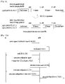
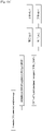
- FIG. 9 and 10 show methods for accessing a network by using a virtual UE scheme of a device.
- Fig.9 shows a claimed embodiment.
- UE of FIG. 9 requests access of a plurality of users to eNB, by performing multiple RACH procedures (or random access procedures).
- the UE firstly requesting access of itself to the eNB should be considered as 'SUE', and any additional UE requesting access to the eNB hereafter should be considered as 'VUE'.
- the UE receives cell search reference signal (RS) from the eNB (S910), the UE performs cell search (or, cell detection) (S920). After the cell search process, the UE synchronizes with the eNB and performs measurement to the eNB by using received channel estimation RS (S930), so that the UE is ready to receive system information from the eNB which is a provisionally selected serving cell for the UE. And, as the UE acknowledges characteristics of the eNB (or cell) by receiving system information from the eNB (S940), the UE determines the number of access requests to be performed to the eNB by using the virtual UE scheme (S950). The number of access requests to be performed is determined when multiple access procedures are required for cell connection, for reasons such as lack of the number of transmission antennas.
- RS cell search reference signal
- S920 cell detection
- the UE synchronizes with the eNB and performs measurement to the eNB by using received channel estimation RS (S930), so that the
- the UE performs access request procedures for the number determined in S950 (S960 to S990). For example, when the UE confirms that the eNB is a legacy eNB by receiving the system information and two access procedures are required to support high rank transmission and multiple codeword Tx/Rx, the UE performs two access request procedures to establish two different connections with the eNB.
- one user establishing a connection with the eNB firstly through the first access request procedure (S960, S970) is called SUE
- another user establishing another connection with the eNB through the second access request procedure (S980, S990) is called VUE. That is, two different DU groups establish connections with the eNB independent from each other.
- the access procedures should be performed in a way to avoid contention. For example, for a case that access procedures are performed by using RACH (Random Access CHannel) processes, two RACH processes should be distinguished to each other to avoid potential contentions.
- the UE may identify RACH preamble sequences which are available to the eNB. And, the UE may select two RACH preamble sequences from the available sequences and allocate the two sequences for each of the two RACH processes respectively.
- the UE may randomly select the two sequences or an index for one sequence can be obtained by adding certain factor 'i' to an index for another randomly-selected sequence.
- the procedure for selecting the sequences may be understood as allocating physical resources used in RACH process. That is, selecting two different sequences may be understood as allocating two different physical resources for each of two RACH processes.
- the eNB detects resources (sequence, time slot) used for RACH processes and recognizes the two different access requests from the UE.
- the eNB allocates unique UE ID, which is C-RNTI (Cell Radio Network Temporary Identifier) for example, for each of the UE (SUE/VUE). Since the RACH processes were performed by using different RACH preamble sequences and/or resources, no contention is occurred and the eNB can identify the two different RACH processes.
- C-RNTI Cell Radio Network Temporary Identifier
- the UE may perform any additional access request procedure while the UE is connected with the eNB. That is, the UE may determine that additional connection is needed to be added to support higher rank transmission, increased simultaneous codewords transmission, etc. Then, the UE may perform additional access request procedures to add connections with the eNB. In other words, SUE may request the eNB to establish additional connection with one or more VUEs.
- the UE may transmit multiple access requests to the eNB, not only for initial access but also after the initial access and/or while communicating with the eNB.
- uplink transmission power may also be considered while determining the number of additional connections.
- the eNB may allocate new UE IDs for the additional connections via VUEs.
- the UE may perform the multiple access request procedures simultaneously.
- the UE may perform RACH processes by transmitting two different RACH preamble sequences 1, 2 to the eNB at the same time (S1010, S1020).
- the UE should use different RACH preamble sequences for the two different access request procedures, and the UE should also use different RACH resources to avoid any contentions.
- the eNB allocates two different UE IDs for the two different RACH processes (S1030), and notifies the UE with the allocated two UE IDs (S1040). In this case, one identified UE ID is allocated for SUE and another identified UE ID is allocated for VUE, since two RACH procedures are simultaneously performed.
- FIG. 11 is a diagram for a bearer configuration when the virtual UE scheme is applied.
- network entries including eNB recognize the UE requesting for connection establishment is a VUE under virtual UE scheme
- the VUE is connected with the network through preconfigured connection of a SUE while not requesting a new bearer configuration for the VUE to the upper network entries. That is, the bearer which is already configured for the SUE is shared with the VUE.
- each of network entries sets up logical paths for the SUE.
- This scheme supporting data flow through organized configuration is called 'packet define network'.
- eNB among the network entries distinguish SUE/VUE independently to control radio links of the SUE/VUE.
- the eNB recognize the SUE/VUE as one single UE.
- the eNB shares preconfigured bearer of the SUE.
- a global ID is common between the SUE and the VUE, while the UE ID is different between the SUE and the VUE.
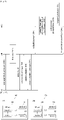
- FIG. 12A and 12B show methods for accessing a network by using a virtual UE scheme of a device.
- UE When virtual UE scheme is applied, UE notifies the eNB and corresponding network entries that the UE itself requesting a access request procedure is a VUE. To provide common QoS management by sharing same bearer between SUE and VUEs, specific network entry should be able to distinguish the VUEs from the SUE. As mentioned before, the specific network entry might be eNB. Thus, when a connection establishment is requested, the requesting SUE notifies the specific network entry that the connection establishment is for a VUE. Or, to avoid influencing current mobile communication system, the notification procedure may be performed by the VUE requesting the connection establishment.
- an initial access request is performed between UE and eNB (S1210, S1215, S1220).
- the UE notifies the eNB that the UE itself is a VUE and no additional bearer is need to be configured for the UE (S1225).
- This notifying procedure may be performed through connection (RRC) configuration request procedure.
- the eNB identifies the VUE and determines to share the bearer of the SUE with the VUE (S1230).
- the eNB directly share preconfigured bearer for the VUE (S1245).
- procedure for configuring a new bearer is omitted in here.
- the UE notifies that the UE itself is a VUE to the eNB, after a new connection is configured (S1275).
- Other procedures may be operated similarly to the procedures of FIG. 12A .
- FIG. 13A , 13B , 13C and 14D show message configurations when a virtual UE scheme is applied.
- exemplary embodiments for notifying the virtual UE scheme to network entries are described.
- a cause/reason for the access request may be notified to the network by indicating that the access request is for a virtual UE scheme. Specifically, it can be implemented by transmitting information indicating 'virtual UE scheme' included in 'establishment cause' field of the access/connection request message of the current communication system.
- UE ID e.g., C-RNTI, MME unique ID, global ID, etc.
- SUE may be reported to indicate whose bearer is requested to be share with the VUE.
- FIG. 13A shows an embodiment of a message configuration used in access/connection request procedures. It can be seen from FIG. 13A that 'establishment cause' field of a connection request message includes information indicating 'virtual UE comunication' (S1310). Also, 'UE ID' field of the message includes UE ID information of one or more grouped DUs consisting the VUE.
- FIG. 13B shows another embodiment of a message configuration transmitted to the eNB.
- 'UE ID of UEs which share bearer' field (S1320) is added to the structure of FIG. 13A . That is, by transmitting UE ID of a SUE whose bearer is requested to be shared, the VUE is also able to notify the eNB that virtual UE scheme is applied.
- the SUE's UE ID is transmitted to the eNB, the information indicating the 'virtual UE scheme' of the 'establishment cause' field (1330) may be omitted.
- FIG. 13C and FIG. 13D show configurations of another message transmitted from the VUE to the eNB.
- the messages structures of FIG. 13C and FIG. 13D may correspond to the message S1275 of FIG. 12B .
- the notification of the virtual UE scheme may be transmitted to the eNB after the connection has been established between the VUE and the eNB, since it is not essential for the eNB and corresponding network entries to know that proceeding connection request is for a VUE.
- the notification (S1340) may be performed through a upper layer signaling that identifing a complete of the connection establishment. For example, RRC connection complete message of the current communication system may be used for this embodiment.
- the notification process is performed to upper network entry, not to the eNB. That is, upper network entry which is directly involved with a bearer configuration may be notified that the connection establishment process has been performed for a VUE through a virtual UE process, since the eNB is not directly involved to a configuration of a bearer.
- a message which is not targeted to an eNB but is targeted to a upper network entry is used, for example NAS message of the current communication system. That is, higher entry information field of the message may include information indicating virtual UE scheme is applied (S1350).
- FIG. 14 shows a method for accessing a network by using virtual UE scheme of a device.
- a virtual UE scheme which requires no addigional signaling for the UE may be applied to reduce impact on the UE.
- the UE does not transmit any information with regard to the virtual UE scheme to the eNB.
- upper network entry which collects and analyzes UE IDs recognizes the UE ID of the VUE and identifies the applied virtual UE scheme.
- bearer sharing may be configured by the upper network entry.
- the eNB reports the UE ID to MME which possessing information of UE IDs and UE characteristics and requests identification and authentication to the MME (S1440).
- the MME (or other upper network entry) checks the UE ID of the VUE and corresponding network characteristics and identifies whether the VUE supports virtual UE scheme or not (S1445).
- the MME checks any preconfigured bearer which can be shared with the VUE (S1450). If there is any available preconfigured bearer, the MME applies the preconfigured bearer for the VUE without generating any new bearer (S1455), and notifies the eNB of PDN connection has been completed (S1460).
- FIG. 15 is a block diagram for a user equipment and an eNB in accordance with the present invention.
- a user equipment 100 and an eNB 200 can include a radio frequency (RF) unit 110/210, a processor 120/220 and a memory 130/230, respectively.
- FIG. 15 shows one-to-one communication environment between the user equipment 100 and the eNB 200, communication environment can be constructed between a plurality of user equipment and the eNB 200.
- the eNB 200 depicted in FIG. 15 can be applied to both a macro cell eNB and a small cell eNB.
- Each of the RF units 110/210 can include a transmission unit 111/211 and a reception unit 112/212, respectively.
- the transmission unit 111 and the reception unit 112 of the user equipment 100 are configured to transmit and receive a signal with the eNB 200 and different user equipments.
- the processor 120 is functionally connected with the transmission unit 111 and the reception unit 112 and is configured to control the transmission unit 111 and the reception unit 112 to transmit and receive signal with different devices. And, the processor 120 performs various processing on a signal to be transmitted and transmits the signal to the transmission unit 111.
- the processor performs processing on a signal received by the reception unit 112.
- the processor 120 can store information included in an exchanged message in the memory 130.
- the user equipment 100 can perform the aforementioned various embodiments of the present invention with the above-mentioned structure.
- the transmission unit 211 and the reception unit 212 of the eNB 200 are configured to transmit and receive a signal with a different eNB and user equipments.
- the processor 220 is functionally connected with the transmission unit 211 and the reception unit 212 and is configured to control the transmission unit 211 and the reception unit 211 to transmit and receive signal with different devices. And, the processor 220 performs various processing on a signal to be transmitted and transmits the signal to the transmission unit 211.
- the processor performs processing on a signal received by the reception unit 212. If necessary, the processor 220 can store information included in an exchanged message in the memory 230.
- the eNB 200 can perform the aforementioned various embodiments of the present invention with the above-mentioned structure.
- Each of the processors 120/220 of the user equipment 100 and the eNB 200 indicates (e.g., control, adjust, manage) operations in the user equipment 100 and the eNB 200.
- Each of the processors 120/220 can be connected with the memory 130/230 storing program codes and data.
- the memory 130/230 is connected with the processor 120/220 and stores an operating system, an application, and general files.
- the processor 120/220 of the present invention can be named by such a terminology as a controller, a microcontroller, a microprocessor, a microcomputer and the like. Meanwhile, the processor can be implemented by hardware, firmware, software and a combination thereof. In the implementation by hardware, ASICs (application specific integrated circuits), DSPs (digital signal processors), DSPDs (digital signal processing devices), PLDs (programmable logic devices), FPGAs (field programmable gate arrays) and the like configured to perform the present invention can be installed in the processor 120/220.
- ASICs application specific integrated circuits
- DSPs digital signal processors
- DSPDs digital signal processing devices
- PLDs programmable logic devices
- FPGAs field programmable gate arrays
- the aforementioned method can be written by a program executable in a computer and can be implemented by a general digital computer capable of operating the program using a computer readable medium. And, data structure used for the aforementioned method can be recorded in the computer readable medium in various means.
- Program storing devices usable for explaining a storing device including an executable computer code to perform various methods of the present invention should not be comprehended as temporary objects such as carrier waves and signals.
- the computer readable medium includes such a storing medium as a magnetic storing medium (e.g., a ROM, a floppy disk, a hard disk and the like) and an optical reading medium (e.g., a CD-ROM, a DVD and the like).
- Embodiments of the present invention are applicable to various wireless access systems including a 3GPP system, a 3GPP2 system, and/or an IEEE 802.xx system. In addition to these wireless access systems, the embodiments of the present invention are applicable to all technical fields in which the wireless access systems find their applications.
Landscapes
- Engineering & Computer Science (AREA)
- Computer Networks & Wireless Communication (AREA)
- Signal Processing (AREA)
- Computer Security & Cryptography (AREA)
- Multimedia (AREA)
- Mobile Radio Communication Systems (AREA)
Claims (10)
- Procédé de communication avec une cellule par un équipement d'utilisateur, UE (100), le procédé comprenant :recevoir (S940) des informations de système sur la cellule en mettant en œuvre (S920) un processus de recherche de cellule ;déterminer (S950) un nombre de requêtes d'accès à la cellule en utilisant un ou plusieurs UE virtuels, VUE, sur la base des informations de système sur la cellule, quand il est déterminé qu'une pluralité de procédures d'accès sont nécessaires en raison du manque d'un nombre d'antennes d'émission de l'UE nécessaires pour prendre en charge une émission de rang élevé et une émission/réception, Tx/Rx, de multiples mots de code, dans lequel chacun des un ou plusieurs VUE est configuré avec une combinaison différente d'unités d'antenne distribuées de l'UE ;mettre en œuvre (S960, S970, S980, S990), respectivement, le nombre de requêtes d'accès à la cellule, dans lequel chacune du nombre des requêtes d'accès est mise en œuvre en utilisant des ressources d'accès aléatoire différentes, dans lequel une première requête d'accès parmi le nombre de requêtes d'accès est considérée comme devant être mise en œuvre par un UE substantif, SUE, requérant une connexion initiale, et dans lequel une ou plusieurs secondes requêtes d'accès après la première requête d'accès sont considérées comme devant être mises en œuvre par les un ou plusieurs VUE requérant des connexions additionnelles ;recevoir, respectivement, un identificateur différent pour chacune du nombre des requêtes d'accès ; etcommuniquer avec la cellule via la connexion initiale et les connexions additionnelles.
- Procédé selon la revendication 1, dans lequel le nombre des requêtes d'accès sont mises en œuvre respectivement sur la base de différentes séquences de préambule d'accès aléatoire.
- Procédé selon la revendication 2, dans lequel les différentes séquences de préambule d'accès aléatoire sont sélectionnées aléatoirement parmi une pluralité de séquences disponibles.
- Procédé selon la revendication 1, comprenant en outre l'émission d'un signal informant que le nombre des requêtes d'accès sont associées à l'UE.
- Procédé selon la revendication 1, dans lequel les unités d'antenne distribuées sont distribuées l'une par rapport à l'autre sur un véhicule et sont connectées à une unité centrale, CU.
- Équipement d'utilisateur, UE (100), configuré pour communiquer avec une cellule, l'UE (100) comprenant :un émetteur (112) ;un récepteur (114) ; etun processeur (120) configuré pour contrôler l'émetteur (112) et le récepteur (114),dans lequel le processeur (120) est configuré pour :recevoir des informations de système sur la cellule en mettant en œuvre un processus de recherche de cellule ;déterminer un nombre de requêtes d'accès à la cellule en utilisant un ou plusieurs UE virtuels, VUE, sur la base des informations de système sur la cellule, quand il est déterminé qu'une pluralité de procédures d'accès sont nécessaires en raison du manque d'un nombre d'antennes d'émission de l'UE nécessaires pour prendre en charge une émission de rang élevé et une émission/réception, Tx/Rx, de multiples mots de code, dans lequel chacun des un ou plusieurs VUE est configuré avec une combinaison différente d'unités d'antenne distribuées de l'UE ;mettre en œuvre respectivement le nombre de requêtes d'accès à la cellule, dans lequel chacune du nombre des requêtes d'accès est mise en œuvre en utilisant des ressources d'accès aléatoire différentes, dans lequel une première requête d'accès parmi le nombre des requêtes d'accès est considérée comme devant mise en œuvre par un UE substantif, SUE, requérant une connexion initiale, et dans lequel une ou plusieurs secondes requêtes d'accès après la première requête d'accès sont considérées comme devant être mises en œuvre par les un ou plusieurs VUE requérant des connexions additionnelles ;recevoir respectivement un identificateur différent pour chacune du nombre des requêtes d'accès ; etcommuniquer avec la cellule via la connexion initiale et les connexions additionnelles.
- UE (100) selon la revendication 6, dans lequel le nombre des requêtes d'accès sont mises en œuvre respectivement sur la base de différentes séquences de préambule d'accès aléatoire.
- UE (100) selon la revendication 7, dans lequel les différentes séquences de préambule d'accès aléatoire sont sélectionnées aléatoirement parmi une pluralité de séquences disponibles.
- UE (100) selon la revendication 6, dans lequel le processeur (120) est configuré en outre pour :
émettre un signal informant que le nombre des requêtes d'accès sont associées à l'UE. - UE (100) selon la revendication 6, dans lequel les unités d'antenne distribuées sont distribuées l'une par rapport à l'autre sur un véhicule et sont connectées à une unité centrale, CU.
Applications Claiming Priority (2)
| Application Number | Priority Date | Filing Date | Title |
|---|---|---|---|
| US201562184912P | 2015-06-26 | 2015-06-26 | |
| PCT/KR2016/000729 WO2016208837A1 (fr) | 2015-06-26 | 2016-01-22 | Procédé pour accéder à un réseau au moyen d'un schéma d'ue virtuel |
Publications (3)
| Publication Number | Publication Date |
|---|---|
| EP3314972A1 EP3314972A1 (fr) | 2018-05-02 |
| EP3314972A4 EP3314972A4 (fr) | 2019-01-09 |
| EP3314972B1 true EP3314972B1 (fr) | 2022-11-30 |
Family
ID=57585056
Family Applications (1)
| Application Number | Title | Priority Date | Filing Date |
|---|---|---|---|
| EP16814550.6A Active EP3314972B1 (fr) | 2015-06-26 | 2016-01-22 | Procédé pour accéder à un réseau au moyen d'un schéma d'ue virtuel et ue correspondant |
Country Status (5)
| Country | Link |
|---|---|
| US (2) | US10555363B2 (fr) |
| EP (1) | EP3314972B1 (fr) |
| JP (1) | JP6783803B2 (fr) |
| CN (1) | CN107810657B (fr) |
| WO (2) | WO2016208836A1 (fr) |
Families Citing this family (12)
| Publication number | Priority date | Publication date | Assignee | Title |
|---|---|---|---|---|
| CN107979402B (zh) * | 2016-10-25 | 2020-09-08 | 华为技术有限公司 | 一种信道状态信息测量方法及装置 |
| WO2018083624A1 (fr) | 2016-11-04 | 2018-05-11 | Telefonaktiebolaget Lm Ericsson (Publ) | Procédés et appareils pour gérer une défaillance de faisceau |
| WO2018143595A1 (fr) * | 2017-02-02 | 2018-08-09 | 엘지전자 주식회사 | Procédé d'émission et de réception de signal entre une station de base et un terminal de véhicule dans un système de communication à antennes réparties, et appareil associé |
| CN116506079A (zh) * | 2017-04-27 | 2023-07-28 | 三菱电机株式会社 | 通信系统 |
| WO2019074242A1 (fr) * | 2017-10-12 | 2019-04-18 | 한국전자통신연구원 | Procédé et dispositif de communication pour un véhicule à vitesse ultra-élevée |
| WO2020014973A1 (fr) * | 2018-07-20 | 2020-01-23 | 北京小米移动软件有限公司 | Procédé de détermination de niveau mcs, dispositif, terminal et support d'informations |
| CN113169442A (zh) * | 2018-12-10 | 2021-07-23 | Lg电子株式会社 | 搭载于车辆的天线系统 |
| EP3783932B1 (fr) * | 2019-08-23 | 2022-09-21 | Nokia Solutions and Networks Oy | Réception de messages de communication de véhicule |
| WO2021172631A1 (fr) * | 2020-02-28 | 2021-09-02 | 엘지전자 주식회사 | Procédé de réalisation, par un ue, d'un accès initial à une station de base dans un système de communication sans fil, et dispositif associé |
| US11072310B1 (en) * | 2020-04-15 | 2021-07-27 | GM Global Technology Operations LLC | Method and system to mitigate smart phone battery drainage while using a virtual key to access a vehicle |
| CN112332935B (zh) * | 2020-11-27 | 2023-01-31 | 中咨数据有限公司 | 一种基于无线通信的信道状态监测方法 |
| US12368463B2 (en) * | 2021-07-21 | 2025-07-22 | Molex, Llc | Vehicular systems including distributed active antennas, adaptive cellphone evolution, and/or integrated access and backhaul |
Family Cites Families (19)
| Publication number | Priority date | Publication date | Assignee | Title |
|---|---|---|---|---|
| KR101424258B1 (ko) | 2006-08-23 | 2014-08-13 | 엘지전자 주식회사 | 무선통신 시스템에서 랜덤 액세스 과정을 수행하는 방법 |
| US8194694B2 (en) | 2007-10-24 | 2012-06-05 | Sharp Kabushiki Kaisha | Mobile communications system, base station apparatus, mobile station apparatus and mobile communications method |
| US8553590B2 (en) | 2007-12-12 | 2013-10-08 | Telefonaktiebolaget Lm Ericsson (Publ) | Methods and devices for communicating on a radio channel based on jointly encoding a preamble format with random access configuration |
| US8780816B2 (en) * | 2008-08-12 | 2014-07-15 | Qualcomm Incorporated | Handling uplink grant in random access response |
| US20100234071A1 (en) | 2009-03-12 | 2010-09-16 | Comsys Communication & Signal Processing Ltd. | Vehicle integrated communications system |
| KR20110033030A (ko) | 2009-09-24 | 2011-03-30 | 엘지전자 주식회사 | 무선 통신 시스템에서 소정의 프레임 구조를 이용하여 신호를 송수신하는 장치 및 방법 |
| CN102550117A (zh) | 2009-09-28 | 2012-07-04 | 诺基亚公司 | 蜂窝辅助d2d网络中的d2d探测的随机接入过程再用 |
| GB2484922B (en) * | 2010-10-25 | 2014-10-08 | Sca Ipla Holdings Inc | Infrastructure equipment and method |
| GB2487908B (en) * | 2011-02-04 | 2015-06-17 | Sca Ipla Holdings Inc | Telecommunications method and system |
| WO2012122670A1 (fr) | 2011-03-14 | 2012-09-20 | Telefonaktiebolaget L M Ericsson (Publ) | Procédé et dispositif relatifs à une technique de relais |
| WO2012134155A2 (fr) | 2011-03-28 | 2012-10-04 | 엘지전자 주식회사 | Procédé et dispositif pour accès aléatoire dans un système de communication mobile |
| CN102739708B (zh) * | 2011-04-07 | 2015-02-04 | 腾讯科技(深圳)有限公司 | 一种基于云平台访问第三方应用的系统及方法 |
| GB2493703C (en) * | 2011-08-11 | 2020-03-04 | Sca Ipla Holdings Inc | OFDM subcarrier allocations in wireless telecommunications systems |
| CN103765966B (zh) | 2011-09-05 | 2018-02-23 | Lg电子株式会社 | 控制上行链路信号传输功率的终端设备及其方法 |
| US9137841B2 (en) * | 2011-10-03 | 2015-09-15 | Mediatek Inc. | Enhancement for scheduling request triggering based on traffic condition |
| US9185690B2 (en) * | 2012-02-29 | 2015-11-10 | Sharp Kabushiki Kaisha | Allocating and determining resources for a device-to-device link |
| US8682283B2 (en) | 2012-06-09 | 2014-03-25 | Apple Inc. | Adjusting connection states of a mobile wireless device |
| CN103974446B (zh) | 2013-01-30 | 2018-07-31 | 华为技术有限公司 | 一种随机接入方法及用户设备 |
| EP2984902B1 (fr) | 2013-04-11 | 2018-07-11 | Nec Corporation | Procédé et structure de réseau pour assurer une connectivité de dispositifs à un réseau d'accès radio |
-
2016
- 2016-01-20 WO PCT/KR2016/000596 patent/WO2016208836A1/fr not_active Ceased
- 2016-01-20 US US15/738,429 patent/US10555363B2/en not_active Expired - Fee Related
- 2016-01-22 US US15/738,765 patent/US10477612B2/en active Active
- 2016-01-22 JP JP2017563621A patent/JP6783803B2/ja active Active
- 2016-01-22 EP EP16814550.6A patent/EP3314972B1/fr active Active
- 2016-01-22 CN CN201680036815.2A patent/CN107810657B/zh active Active
- 2016-01-22 WO PCT/KR2016/000729 patent/WO2016208837A1/fr not_active Ceased
Also Published As
| Publication number | Publication date |
|---|---|
| US20180184473A1 (en) | 2018-06-28 |
| US20180192466A1 (en) | 2018-07-05 |
| WO2016208837A1 (fr) | 2016-12-29 |
| WO2016208836A1 (fr) | 2016-12-29 |
| JP2018518902A (ja) | 2018-07-12 |
| CN107810657A (zh) | 2018-03-16 |
| US10477612B2 (en) | 2019-11-12 |
| EP3314972A4 (fr) | 2019-01-09 |
| EP3314972A1 (fr) | 2018-05-02 |
| JP6783803B2 (ja) | 2020-11-11 |
| CN107810657B (zh) | 2021-05-11 |
| US10555363B2 (en) | 2020-02-04 |
Similar Documents
| Publication | Publication Date | Title |
|---|---|---|
| US10477612B2 (en) | Method for accessing a network by using a virtual UE scheme | |
| CN109845129B (zh) | 针对新无线电在弹性帧结构中进行波束成形扫描和训练 | |
| US12401412B2 (en) | Iterative transmit refinement | |
| KR20230006489A (ko) | 업링크 기준 신호에 기초하여 빔 관리를 수행하는 방법 및 장치 | |
| US10554343B2 (en) | Method by which terminal receives retransmitted data when virtual terminal scheme is applied | |
| US11006459B2 (en) | Random access technique in mobile communication system using beamforming | |
| US12342183B2 (en) | Method for transmitting and receiving data repeatedly transmitted based on a transmission configuration indication (TCI) field in wireless communication system, and device for same | |
| WO2019214682A1 (fr) | Procédé et dispositif de communication | |
| US12375246B2 (en) | Techniques for indicating sounding reference signal resources | |
| US11323945B2 (en) | Method for performing random access and handover | |
| US20250133416A1 (en) | Wireless relay device and communication method | |
| EP4229946B1 (fr) | Allocation des ressources inter-user equipment | |
| US20250039685A1 (en) | Wireless relay device and communication method | |
| US20250365044A1 (en) | Orbital angular momentum data channels configuration | |
| KR20220102613A (ko) | 초기 사이드링크 제어 정보 통신을 통한 후속 사이드링크 송신들을 위한 자원들의 예비 | |
| KR20230015012A (ko) | 무선 통신 시스템에서 xdd 단말을 위한 통신 방법 및 장치 | |
| WO2021227055A1 (fr) | Affinement de faisceau ul demandé par un ue | |
| WO2024042866A1 (fr) | Terminal, procédé de communication sans fil, et station de base | |
| US20250048125A1 (en) | Wireless relay device and communication method | |
| KR102956502B1 (ko) | 무선 통신을 위한 방법 및 장치 | |
| EP4468768A1 (fr) | Dispositif de relais radio et procédé de communication | |
| US20250048124A1 (en) | Wireless relay device and communication method | |
| US20240267954A1 (en) | Communication method and device implementing a network communication procedure with early channel state information acquisition | |
| WO2025083901A1 (fr) | Dispositif de communication sans fil et procédé de communication sans fil | |
| WO2025083904A1 (fr) | Dispositif de communications sans fil, et procédé de communications sans fil |
Legal Events
| Date | Code | Title | Description |
|---|---|---|---|
| STAA | Information on the status of an ep patent application or granted ep patent |
Free format text: STATUS: THE INTERNATIONAL PUBLICATION HAS BEEN MADE |
|
| PUAI | Public reference made under article 153(3) epc to a published international application that has entered the european phase |
Free format text: ORIGINAL CODE: 0009012 |
|
| STAA | Information on the status of an ep patent application or granted ep patent |
Free format text: STATUS: REQUEST FOR EXAMINATION WAS MADE |
|
| 17P | Request for examination filed |
Effective date: 20180115 |
|
| AK | Designated contracting states |
Kind code of ref document: A1 Designated state(s): AL AT BE BG CH CY CZ DE DK EE ES FI FR GB GR HR HU IE IS IT LI LT LU LV MC MK MT NL NO PL PT RO RS SE SI SK SM TR |
|
| AX | Request for extension of the european patent |
Extension state: BA ME |
|
| DAV | Request for validation of the european patent (deleted) | ||
| DAX | Request for extension of the european patent (deleted) | ||
| A4 | Supplementary search report drawn up and despatched |
Effective date: 20181212 |
|
| RIC1 | Information provided on ipc code assigned before grant |
Ipc: H04W 8/26 20090101ALI20181206BHEP Ipc: H04W 74/08 20090101AFI20181206BHEP Ipc: H04W 68/00 20090101ALI20181206BHEP |
|
| STAA | Information on the status of an ep patent application or granted ep patent |
Free format text: STATUS: EXAMINATION IS IN PROGRESS |
|
| 17Q | First examination report despatched |
Effective date: 20200213 |
|
| GRAP | Despatch of communication of intention to grant a patent |
Free format text: ORIGINAL CODE: EPIDOSNIGR1 |
|
| STAA | Information on the status of an ep patent application or granted ep patent |
Free format text: STATUS: GRANT OF PATENT IS INTENDED |
|
| INTG | Intention to grant announced |
Effective date: 20220713 |
|
| GRAS | Grant fee paid |
Free format text: ORIGINAL CODE: EPIDOSNIGR3 |
|
| GRAA | (expected) grant |
Free format text: ORIGINAL CODE: 0009210 |
|
| STAA | Information on the status of an ep patent application or granted ep patent |
Free format text: STATUS: THE PATENT HAS BEEN GRANTED |
|
| AK | Designated contracting states |
Kind code of ref document: B1 Designated state(s): AL AT BE BG CH CY CZ DE DK EE ES FI FR GB GR HR HU IE IS IT LI LT LU LV MC MK MT NL NO PL PT RO RS SE SI SK SM TR |
|
| REG | Reference to a national code |
Ref country code: CH Ref legal event code: EP Ref country code: GB Ref legal event code: FG4D |
|
| REG | Reference to a national code |
Ref country code: AT Ref legal event code: REF Ref document number: 1535688 Country of ref document: AT Kind code of ref document: T Effective date: 20221215 Ref country code: DE Ref legal event code: R096 Ref document number: 602016076653 Country of ref document: DE |
|
| REG | Reference to a national code |
Ref country code: IE Ref legal event code: FG4D |
|
| REG | Reference to a national code |
Ref country code: LT Ref legal event code: MG9D |
|
| REG | Reference to a national code |
Ref country code: NL Ref legal event code: MP Effective date: 20221130 |
|
| PG25 | Lapsed in a contracting state [announced via postgrant information from national office to epo] |
Ref country code: SE Free format text: LAPSE BECAUSE OF FAILURE TO SUBMIT A TRANSLATION OF THE DESCRIPTION OR TO PAY THE FEE WITHIN THE PRESCRIBED TIME-LIMIT Effective date: 20221130 Ref country code: PT Free format text: LAPSE BECAUSE OF FAILURE TO SUBMIT A TRANSLATION OF THE DESCRIPTION OR TO PAY THE FEE WITHIN THE PRESCRIBED TIME-LIMIT Effective date: 20230331 Ref country code: NO Free format text: LAPSE BECAUSE OF FAILURE TO SUBMIT A TRANSLATION OF THE DESCRIPTION OR TO PAY THE FEE WITHIN THE PRESCRIBED TIME-LIMIT Effective date: 20230228 Ref country code: LT Free format text: LAPSE BECAUSE OF FAILURE TO SUBMIT A TRANSLATION OF THE DESCRIPTION OR TO PAY THE FEE WITHIN THE PRESCRIBED TIME-LIMIT Effective date: 20221130 Ref country code: FI Free format text: LAPSE BECAUSE OF FAILURE TO SUBMIT A TRANSLATION OF THE DESCRIPTION OR TO PAY THE FEE WITHIN THE PRESCRIBED TIME-LIMIT Effective date: 20221130 Ref country code: ES Free format text: LAPSE BECAUSE OF FAILURE TO SUBMIT A TRANSLATION OF THE DESCRIPTION OR TO PAY THE FEE WITHIN THE PRESCRIBED TIME-LIMIT Effective date: 20221130 |
|
| REG | Reference to a national code |
Ref country code: AT Ref legal event code: MK05 Ref document number: 1535688 Country of ref document: AT Kind code of ref document: T Effective date: 20221130 |
|
| PG25 | Lapsed in a contracting state [announced via postgrant information from national office to epo] |
Ref country code: RS Free format text: LAPSE BECAUSE OF FAILURE TO SUBMIT A TRANSLATION OF THE DESCRIPTION OR TO PAY THE FEE WITHIN THE PRESCRIBED TIME-LIMIT Effective date: 20221130 Ref country code: PL Free format text: LAPSE BECAUSE OF FAILURE TO SUBMIT A TRANSLATION OF THE DESCRIPTION OR TO PAY THE FEE WITHIN THE PRESCRIBED TIME-LIMIT Effective date: 20221130 Ref country code: LV Free format text: LAPSE BECAUSE OF FAILURE TO SUBMIT A TRANSLATION OF THE DESCRIPTION OR TO PAY THE FEE WITHIN THE PRESCRIBED TIME-LIMIT Effective date: 20221130 Ref country code: IS Free format text: LAPSE BECAUSE OF FAILURE TO SUBMIT A TRANSLATION OF THE DESCRIPTION OR TO PAY THE FEE WITHIN THE PRESCRIBED TIME-LIMIT Effective date: 20230330 Ref country code: HR Free format text: LAPSE BECAUSE OF FAILURE TO SUBMIT A TRANSLATION OF THE DESCRIPTION OR TO PAY THE FEE WITHIN THE PRESCRIBED TIME-LIMIT Effective date: 20221130 Ref country code: GR Free format text: LAPSE BECAUSE OF FAILURE TO SUBMIT A TRANSLATION OF THE DESCRIPTION OR TO PAY THE FEE WITHIN THE PRESCRIBED TIME-LIMIT Effective date: 20230301 |
|
| PG25 | Lapsed in a contracting state [announced via postgrant information from national office to epo] |
Ref country code: NL Free format text: LAPSE BECAUSE OF FAILURE TO SUBMIT A TRANSLATION OF THE DESCRIPTION OR TO PAY THE FEE WITHIN THE PRESCRIBED TIME-LIMIT Effective date: 20221130 |
|
| PG25 | Lapsed in a contracting state [announced via postgrant information from national office to epo] |
Ref country code: SM Free format text: LAPSE BECAUSE OF FAILURE TO SUBMIT A TRANSLATION OF THE DESCRIPTION OR TO PAY THE FEE WITHIN THE PRESCRIBED TIME-LIMIT Effective date: 20221130 Ref country code: RO Free format text: LAPSE BECAUSE OF FAILURE TO SUBMIT A TRANSLATION OF THE DESCRIPTION OR TO PAY THE FEE WITHIN THE PRESCRIBED TIME-LIMIT Effective date: 20221130 Ref country code: EE Free format text: LAPSE BECAUSE OF FAILURE TO SUBMIT A TRANSLATION OF THE DESCRIPTION OR TO PAY THE FEE WITHIN THE PRESCRIBED TIME-LIMIT Effective date: 20221130 Ref country code: DK Free format text: LAPSE BECAUSE OF FAILURE TO SUBMIT A TRANSLATION OF THE DESCRIPTION OR TO PAY THE FEE WITHIN THE PRESCRIBED TIME-LIMIT Effective date: 20221130 Ref country code: CZ Free format text: LAPSE BECAUSE OF FAILURE TO SUBMIT A TRANSLATION OF THE DESCRIPTION OR TO PAY THE FEE WITHIN THE PRESCRIBED TIME-LIMIT Effective date: 20221130 Ref country code: AT Free format text: LAPSE BECAUSE OF FAILURE TO SUBMIT A TRANSLATION OF THE DESCRIPTION OR TO PAY THE FEE WITHIN THE PRESCRIBED TIME-LIMIT Effective date: 20221130 |
|
| PG25 | Lapsed in a contracting state [announced via postgrant information from national office to epo] |
Ref country code: SK Free format text: LAPSE BECAUSE OF FAILURE TO SUBMIT A TRANSLATION OF THE DESCRIPTION OR TO PAY THE FEE WITHIN THE PRESCRIBED TIME-LIMIT Effective date: 20221130 Ref country code: AL Free format text: LAPSE BECAUSE OF FAILURE TO SUBMIT A TRANSLATION OF THE DESCRIPTION OR TO PAY THE FEE WITHIN THE PRESCRIBED TIME-LIMIT Effective date: 20221130 |
|
| REG | Reference to a national code |
Ref country code: DE Ref legal event code: R097 Ref document number: 602016076653 Country of ref document: DE Ref country code: CH Ref legal event code: PL |
|
| PG25 | Lapsed in a contracting state [announced via postgrant information from national office to epo] |
Ref country code: LU Free format text: LAPSE BECAUSE OF NON-PAYMENT OF DUE FEES Effective date: 20230122 |
|
| REG | Reference to a national code |
Ref country code: BE Ref legal event code: MM Effective date: 20230131 |
|
| PLBE | No opposition filed within time limit |
Free format text: ORIGINAL CODE: 0009261 |
|
| STAA | Information on the status of an ep patent application or granted ep patent |
Free format text: STATUS: NO OPPOSITION FILED WITHIN TIME LIMIT |
|
| GBPC | Gb: european patent ceased through non-payment of renewal fee |
Effective date: 20230228 |
|
| PG25 | Lapsed in a contracting state [announced via postgrant information from national office to epo] |
Ref country code: LI Free format text: LAPSE BECAUSE OF NON-PAYMENT OF DUE FEES Effective date: 20230131 Ref country code: CH Free format text: LAPSE BECAUSE OF NON-PAYMENT OF DUE FEES Effective date: 20230131 |
|
| 26N | No opposition filed |
Effective date: 20230831 |
|
| PG25 | Lapsed in a contracting state [announced via postgrant information from national office to epo] |
Ref country code: SI Free format text: LAPSE BECAUSE OF FAILURE TO SUBMIT A TRANSLATION OF THE DESCRIPTION OR TO PAY THE FEE WITHIN THE PRESCRIBED TIME-LIMIT Effective date: 20221130 Ref country code: FR Free format text: LAPSE BECAUSE OF NON-PAYMENT OF DUE FEES Effective date: 20230130 Ref country code: BE Free format text: LAPSE BECAUSE OF NON-PAYMENT OF DUE FEES Effective date: 20230131 |
|
| PG25 | Lapsed in a contracting state [announced via postgrant information from national office to epo] |
Ref country code: GB Free format text: LAPSE BECAUSE OF NON-PAYMENT OF DUE FEES Effective date: 20230228 |
|
| PG25 | Lapsed in a contracting state [announced via postgrant information from national office to epo] |
Ref country code: IE Free format text: LAPSE BECAUSE OF NON-PAYMENT OF DUE FEES Effective date: 20230122 Ref country code: GB Free format text: LAPSE BECAUSE OF NON-PAYMENT OF DUE FEES Effective date: 20230228 |
|
| PG25 | Lapsed in a contracting state [announced via postgrant information from national office to epo] |
Ref country code: IT Free format text: LAPSE BECAUSE OF FAILURE TO SUBMIT A TRANSLATION OF THE DESCRIPTION OR TO PAY THE FEE WITHIN THE PRESCRIBED TIME-LIMIT Effective date: 20221130 |
|
| PG25 | Lapsed in a contracting state [announced via postgrant information from national office to epo] |
Ref country code: MC Free format text: LAPSE BECAUSE OF FAILURE TO SUBMIT A TRANSLATION OF THE DESCRIPTION OR TO PAY THE FEE WITHIN THE PRESCRIBED TIME-LIMIT Effective date: 20221130 |
|
| PG25 | Lapsed in a contracting state [announced via postgrant information from national office to epo] |
Ref country code: MC Free format text: LAPSE BECAUSE OF FAILURE TO SUBMIT A TRANSLATION OF THE DESCRIPTION OR TO PAY THE FEE WITHIN THE PRESCRIBED TIME-LIMIT Effective date: 20221130 |
|
| PG25 | Lapsed in a contracting state [announced via postgrant information from national office to epo] |
Ref country code: BG Free format text: LAPSE BECAUSE OF FAILURE TO SUBMIT A TRANSLATION OF THE DESCRIPTION OR TO PAY THE FEE WITHIN THE PRESCRIBED TIME-LIMIT Effective date: 20221130 |
|
| PG25 | Lapsed in a contracting state [announced via postgrant information from national office to epo] |
Ref country code: BG Free format text: LAPSE BECAUSE OF FAILURE TO SUBMIT A TRANSLATION OF THE DESCRIPTION OR TO PAY THE FEE WITHIN THE PRESCRIBED TIME-LIMIT Effective date: 20221130 |
|
| PG25 | Lapsed in a contracting state [announced via postgrant information from national office to epo] |
Ref country code: CY Free format text: LAPSE BECAUSE OF FAILURE TO SUBMIT A TRANSLATION OF THE DESCRIPTION OR TO PAY THE FEE WITHIN THE PRESCRIBED TIME-LIMIT; INVALID AB INITIO Effective date: 20160122 |
|
| PG25 | Lapsed in a contracting state [announced via postgrant information from national office to epo] |
Ref country code: HU Free format text: LAPSE BECAUSE OF FAILURE TO SUBMIT A TRANSLATION OF THE DESCRIPTION OR TO PAY THE FEE WITHIN THE PRESCRIBED TIME-LIMIT; INVALID AB INITIO Effective date: 20160122 |
|
| PG25 | Lapsed in a contracting state [announced via postgrant information from national office to epo] |
Ref country code: TR Free format text: LAPSE BECAUSE OF FAILURE TO SUBMIT A TRANSLATION OF THE DESCRIPTION OR TO PAY THE FEE WITHIN THE PRESCRIBED TIME-LIMIT Effective date: 20221130 |
|
| PGFP | Annual fee paid to national office [announced via postgrant information from national office to epo] |
Ref country code: DE Payment date: 20251208 Year of fee payment: 11 |