EP3315076A1 - Appareil de biopsie et son procédé de fonctionnement - Google Patents
Appareil de biopsie et son procédé de fonctionnement Download PDFInfo
- Publication number
- EP3315076A1 EP3315076A1 EP17198878.5A EP17198878A EP3315076A1 EP 3315076 A1 EP3315076 A1 EP 3315076A1 EP 17198878 A EP17198878 A EP 17198878A EP 3315076 A1 EP3315076 A1 EP 3315076A1
- Authority
- EP
- European Patent Office
- Prior art keywords
- biopsy
- biopsy needle
- image
- ultrasound
- mode
- Prior art date
- Legal status (The legal status is an assumption and is not a legal conclusion. Google has not performed a legal analysis and makes no representation as to the accuracy of the status listed.)
- Granted
Links
Images



Classifications
-
- A—HUMAN NECESSITIES
- A61—MEDICAL OR VETERINARY SCIENCE; HYGIENE
- A61B—DIAGNOSIS; SURGERY; IDENTIFICATION
- A61B10/00—Instruments for taking body samples for diagnostic purposes; Other methods or instruments for diagnosis, e.g. for vaccination diagnosis, sex determination or ovulation-period determination; Throat striking implements
- A61B10/02—Instruments for taking cell samples or for biopsy
- A61B10/0233—Pointed or sharp biopsy instruments
-
- A—HUMAN NECESSITIES
- A61—MEDICAL OR VETERINARY SCIENCE; HYGIENE
- A61B—DIAGNOSIS; SURGERY; IDENTIFICATION
- A61B8/00—Diagnosis using ultrasonic, sonic or infrasonic waves
- A61B8/08—Clinical applications
- A61B8/0833—Clinical applications involving detecting or locating foreign bodies or organic structures
-
- A—HUMAN NECESSITIES
- A61—MEDICAL OR VETERINARY SCIENCE; HYGIENE
- A61B—DIAGNOSIS; SURGERY; IDENTIFICATION
- A61B8/00—Diagnosis using ultrasonic, sonic or infrasonic waves
- A61B8/08—Clinical applications
-
- A—HUMAN NECESSITIES
- A61—MEDICAL OR VETERINARY SCIENCE; HYGIENE
- A61B—DIAGNOSIS; SURGERY; IDENTIFICATION
- A61B8/00—Diagnosis using ultrasonic, sonic or infrasonic waves
- A61B8/08—Clinical applications
- A61B8/0833—Clinical applications involving detecting or locating foreign bodies or organic structures
- A61B8/0841—Clinical applications involving detecting or locating foreign bodies or organic structures for locating instruments
-
- A—HUMAN NECESSITIES
- A61—MEDICAL OR VETERINARY SCIENCE; HYGIENE
- A61B—DIAGNOSIS; SURGERY; IDENTIFICATION
- A61B8/00—Diagnosis using ultrasonic, sonic or infrasonic waves
- A61B8/42—Details of probe positioning or probe attachment to the patient
- A61B8/4245—Details of probe positioning or probe attachment to the patient involving determining the position of the probe, e.g. with respect to an external reference frame or to the patient
- A61B8/4254—Details of probe positioning or probe attachment to the patient involving determining the position of the probe, e.g. with respect to an external reference frame or to the patient using sensors mounted on the probe
-
- A—HUMAN NECESSITIES
- A61—MEDICAL OR VETERINARY SCIENCE; HYGIENE
- A61B—DIAGNOSIS; SURGERY; IDENTIFICATION
- A61B8/00—Diagnosis using ultrasonic, sonic or infrasonic waves
- A61B8/44—Constructional features of the ultrasonic, sonic or infrasonic diagnostic device
- A61B8/4416—Constructional features of the ultrasonic, sonic or infrasonic diagnostic device related to combined acquisition of different diagnostic modalities, e.g. combination of ultrasound and X-ray acquisitions
-
- A—HUMAN NECESSITIES
- A61—MEDICAL OR VETERINARY SCIENCE; HYGIENE
- A61B—DIAGNOSIS; SURGERY; IDENTIFICATION
- A61B8/00—Diagnosis using ultrasonic, sonic or infrasonic waves
- A61B8/52—Devices using data or image processing specially adapted for diagnosis using ultrasonic, sonic or infrasonic waves
- A61B8/5207—Devices using data or image processing specially adapted for diagnosis using ultrasonic, sonic or infrasonic waves involving processing of raw data to produce diagnostic data, e.g. for generating an image
-
- A—HUMAN NECESSITIES
- A61—MEDICAL OR VETERINARY SCIENCE; HYGIENE
- A61B—DIAGNOSIS; SURGERY; IDENTIFICATION
- A61B10/00—Instruments for taking body samples for diagnostic purposes; Other methods or instruments for diagnosis, e.g. for vaccination diagnosis, sex determination or ovulation-period determination; Throat striking implements
- A61B10/02—Instruments for taking cell samples or for biopsy
- A61B2010/0208—Biopsy devices with actuators, e.g. with triggered spring mechanisms
-
- A—HUMAN NECESSITIES
- A61—MEDICAL OR VETERINARY SCIENCE; HYGIENE
- A61B—DIAGNOSIS; SURGERY; IDENTIFICATION
- A61B17/00—Surgical instruments, devices or methods
- A61B17/34—Trocars; Puncturing needles
- A61B17/3403—Needle locating or guiding means
- A61B2017/3413—Needle locating or guiding means guided by ultrasound
-
- A—HUMAN NECESSITIES
- A61—MEDICAL OR VETERINARY SCIENCE; HYGIENE
- A61B—DIAGNOSIS; SURGERY; IDENTIFICATION
- A61B8/00—Diagnosis using ultrasonic, sonic or infrasonic waves
- A61B8/08—Clinical applications
- A61B8/0825—Clinical applications for diagnosis of the breast, e.g. mammography
-
- A—HUMAN NECESSITIES
- A61—MEDICAL OR VETERINARY SCIENCE; HYGIENE
- A61B—DIAGNOSIS; SURGERY; IDENTIFICATION
- A61B8/00—Diagnosis using ultrasonic, sonic or infrasonic waves
- A61B8/08—Clinical applications
- A61B8/0833—Clinical applications involving detecting or locating foreign bodies or organic structures
- A61B8/085—Clinical applications involving detecting or locating foreign bodies or organic structures for locating body or organic structures, e.g. tumours, calculi, blood vessels, nodules
-
- A—HUMAN NECESSITIES
- A61—MEDICAL OR VETERINARY SCIENCE; HYGIENE
- A61B—DIAGNOSIS; SURGERY; IDENTIFICATION
- A61B8/00—Diagnosis using ultrasonic, sonic or infrasonic waves
- A61B8/44—Constructional features of the ultrasonic, sonic or infrasonic diagnostic device
- A61B8/4405—Device being mounted on a trolley
-
- A—HUMAN NECESSITIES
- A61—MEDICAL OR VETERINARY SCIENCE; HYGIENE
- A61B—DIAGNOSIS; SURGERY; IDENTIFICATION
- A61B8/00—Diagnosis using ultrasonic, sonic or infrasonic waves
- A61B8/44—Constructional features of the ultrasonic, sonic or infrasonic diagnostic device
- A61B8/4427—Device being portable or laptop-like
-
- A—HUMAN NECESSITIES
- A61—MEDICAL OR VETERINARY SCIENCE; HYGIENE
- A61B—DIAGNOSIS; SURGERY; IDENTIFICATION
- A61B8/00—Diagnosis using ultrasonic, sonic or infrasonic waves
- A61B8/46—Ultrasonic, sonic or infrasonic diagnostic devices with special arrangements for interfacing with the operator or the patient
- A61B8/467—Ultrasonic, sonic or infrasonic diagnostic devices with special arrangements for interfacing with the operator or the patient characterised by special input means
Definitions
- the present disclosure generally relates to a biopsy apparatus and a method of operating the biopsy apparatus. More particularly, the present disclosure relates to an apparatus including a biopsy needle attached to an ultrasound probe and a method of registering and correcting ultrasound images and images of other modalities.
- a typical ultrasound diagnosis apparatus transmits an ultrasound signal generated by a transducer of an ultrasound probe to a subject for diagnosis, such as a human body, and may receive a signal reflected from the subject. After processing the received signal, the ultrasound diagnosis apparatus can generate images of a region (e.g., soft tissue or blood stream) inside the subject.
- a region e.g., soft tissue or blood stream
- These ultrasound diagnosis apparatuses may also take biopsies by inserting a medical needle such as a biopsy needle into a lesion region of the subject body. While the biopsy operation is underway, the medical technician or operator may use the ultrasound features of the apparatus to observe the inside of the subject's body.
- the biopsy feature may be used to diagnose cancer or other diseases.
- tumors or inflammatory masses may grow on various organs such as livers, kidneys, pancreases, breasts, etc., and biopsies may be utilized in order to distinguish a malignant tumor requiring surgery or administration of anticancer drugs from a benign tumor or an inflammatory mass.
- the biopsy needle includes a position tracking sensor.
- the ultrasound probe need to be redesigned to have a groove such that a bracket or a guide jig can be mounted in the body of the ultrasound probe.
- a biopsy apparatus that includes a biopsy needle which includes a sensor, and a method of operating the biopsy apparatus for registering an ultrasound image and an image of another modality and performing a biopsy function, whereby the structure of the body of the ultrasound probe need not be changed.
- a biopsy apparatus includes an ultrasound probe configured to transmit an ultrasound signal to an object and to receive an echo signal reflected from the object, to thereby obtain an ultrasound image; a biopsy needle located at a side of the ultrasound probe, and including an electromagnetic (EM) sensor; a tracker configured to obtain position and movement direction information of the biopsy needle; and a controller configured to receive, from the tracker, the position and movement direction information of the biopsy needle, and to determine an operation mode based on the position and movement direction information, wherein the operation mode is selected from an image registration mode where image registration is performed between the ultrasound image and an image of another modality, and a biopsy mode where a biopsy is performed using the biopsy needle.
- EM electromagnetic
- a method includes obtaining position and movement direction information of the biopsy needle using an electromagnetic (EM) sensor included in the biopsy needle; determining an operation mode based on the position and movement direction information, wherein the operation mode is selected from an image registration mode where image registration is performed between an ultrasound image and an image of another modality, and a biopsy mode where a biopsy is performed using the biopsy needle; and when the operation mode is the biopsy mode, correcting the image of another modality for registration with the ultrasound image.
- EM electromagnetic
- a computer-readable recording medium includes a program for implementing the above method using a computer.
- image may refer medical images obtained by a medical imaging apparatus such as an ultrasound imaging apparatus, a magnetic resonance imaging (MRI) apparatus, a computed tomography (CT) apparatus, an X-ray apparatus, or the like.
- MRI magnetic resonance imaging
- CT computed tomography
- X-ray apparatus or the like.
- object may be a target to be imaged such as a human body, an animal body, or a part of the human or animal.
- the object may be a body part (such as an organ) or a phantom.
- ultrasound image may refer to images of an object generated from ultrasound signals transmitted to the object and ultrasound echo signals reflected from the object.
- registration may refer to the process of one-to-one matching medical images of different modalities.
- the term "and/or" includes any and all combinations of one or more of the associated listed items. Expressions such as “at least one of,” when preceding a list of elements, modify the entire list of elements and do not modify the individual elements of the list.
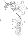
- FIG. 1 is a schematic diagram illustrating a biopsy apparatus 100 and a method of operating the biopsy apparatus 100, according to an embodiment.
- the biopsy apparatus 100 may be a medical apparatus for obtaining ultrasound images of the object 10, and for performing biopsies and medical treatments.
- the biopsy apparatus 100 may include an ultrasound imaging apparatus 110, an ultrasound probe 120, a biopsy needle 130, a guide cover 132, a tracker 140, and an electromagnetic field generator 150.
- the ultrasound probe 120 may transmit an ultrasound signal to the object 10, and may receive an ultrasound echo signal reflected from the object 10.
- the ultrasound probe 120 is connected to the ultrasound imaging apparatus 110 via a wire, but the present disclosure is so limited.
- the ultrasound probe 120 may be wirelessly connected to the ultrasound imaging apparatus 110.
- the ultrasound imaging apparatus 110 may receive the ultrasound echo signal from the ultrasound probe 120, and may perform image-processing on the ultrasound echo signal to generate ultrasound images of a region inside the object 10.
- the ultrasound imaging apparatus 110 may include a display 114 to display the ultrasound images.
- the biopsy needle 130 may be a medical needle that is inserted into a lesion region of the object 10 through a hole in the object body.
- the biopsy needle 130 may Clear TrackTM or Virtual TrackTM needles.
- the biopsy needle 130 may be located at one side of the ultrasound probe 120.
- the biopsy needle 130 may be located in the guide cover 132 attached to one side of the ultrasound probe 120.
- the biopsy needle 130 may be enveloped by the guide cover 132 and may extend from the guide cover 132 or retract into the guide cover 132.
- the biopsy needle 130 enveloped by the guide cover 132 may be inserted toward the inside of the object 10.
- the electromagnetic field generator 150 may be located near the ultrasound probe 120 and the biopsy needle 130, and may generate an electromagnetic field within a preset range.
- the electromagnetic field generated by the electromagnetic field generator 150 can be used to detect the positions of the ultrasound probe 120 and the biopsy needle 130 in a three-dimensional (3D) coordinates system.
- the biopsy needle 130 may include an electromagnetic sensor (EM sensor) to detect the electromagnetic field.
- EM sensor electromagnetic sensor
- the tracker 140 may obtain position and movement direction information regarding the biopsy needle 130 when it is inserted into the object 10 for biopsy.
- the tracker 140 may track the movement direction of the biopsy needle 130 using the EM sensor and record the movement direction as a direction vector in a 3D coordinates system.
- the ultrasound imaging apparatus 110 may receive the position and movement direction information regarding the biopsy needle 130 from the tracker 140. In turn, the ultrasound imaging apparatus 110 may determine an operation mode based on the received position and movement direction information.
- the operation modes may include an image registration mode where ultrasound images are registered with images of other modalities, and a biopsy mode using the biopsy needle 130.
- the ultrasound imaging apparatus 110 may pause images of other modalities so that the images of other modalities can be properly registered with the ultrasound images.
- the image may include, but is not limited to, at least one of a CT image, an MRI image, and an X-ray image.
- the ultrasound imaging apparatus 110 may pause the images of other modalities so that they can be properly registered with the ultrasound images.
- the biopsy needle 130 including a position tracking sensor such as the EM sensor In order to attach the biopsy needle 130 including a position tracking sensor such as the EM sensor to the ultrasound probe 120, it is required to re-design the ultrasound probe 120 by making a groove for attaching a member such as a bracket to the body of the ultrasound probe 120.
- the biopsy apparatus 100 according to the embodiment of FIG. 1 may perform both image registration and biopsy by using the biopsy needle 130 with an EM sensor. Thus, there is no need to re-design the ultrasound probe 120 and therefore the design and manufacturing costs of the biopsy apparatus may be reduced.
- FIG. 2 is a block diagram illustrating a biopsy apparatus 200, according to an embodiment.
- the biopsy apparatus 200 may include an ultrasound imaging apparatus 210, an ultrasound probe 220, a biopsy needle 230, a tracker 240, and an electromagnetic field generator 250.
- the ultrasound imaging apparatus 210 may receive an ultrasound echo signal from the ultrasound probe 220 and may perform image processing on the received ultrasound echo signal, in order to generate ultrasound images of a region inside an object.
- the ultrasound imaging apparatus 210 may be, but is not limited to, a cart-type apparatus.
- the ultrasound imaging apparatus 210 may be a portable-type ultrasound imaging apparatus implemented by systems such as Picture Archiving and Communication System (PACS) viewers, smartphones, laptop computers, tablet personal computers (tablet PCs), personal digital assistants (PDAs), etc.
- PACS Picture Archiving and Communication System
- smartphones smartphones, laptop computers, tablet personal computers (tablet PCs), personal digital assistants (PDAs), etc.
- PDAs personal digital assistants
- the ultrasound imaging apparatus 210 may include a controller 212 and a display 214. Although not illustrated in FIG. 2 , the ultrasound imaging apparatus 210 may further include a user input unit to receive user input from the operator of the ultrasound imaging apparatus 210.
- the user input unit may be implemented as a button, a keypad, a mouse, a trackball, a touchscreen, etc. For example, the user input may select an operation mode of the ultrasound imaging apparatus 210.
- the ultrasound probe 220, the tracker 240, and the electromagnetic field generator 250 may be connected to the ultrasound imaging apparatus 210 via wires or may be connected wirelessly.
- the controller 212 may control the operations of the ultrasound probe 220, the tracker 240, and the electromagnetic field generator 250, and manage the signal flow between components in the ultrasound imaging apparatus 210.
- the controller 212 may be a hardware unit including a memory to store programs, algorithms, data, etc. for performing operations of the ultrasound imaging apparatus 210.
- the hardware unit may also include a processor to process the program, algorithms, and data stored in the memory.
- the processor may include a microprocessor or any suitable type of processing circuitry, such as one or more general-purpose processors (e.g., ARM-based processors), a Digital Signal Processor (DSP), a Programmable Logic Device (PLD), an Application-Specific Integrated Circuit (ASIC), a Field-Programmable Gate Array (FPGA), a Graphical Processing Unit (GPU), a video card controller, etc.
- general-purpose processors e.g., ARM-based processors
- DSP Digital Signal Processor
- PLD Programmable Logic Device
- ASIC Application-Specific Integrated Circuit
- FPGA Field-Programmable Gate Array
- GPU Graphical Processing Unit
- the controller 212 may determine an operation mode based on position and movement direction information of the biopsy needle 230 which is obtained from the tracker 240. Operation modes includes image registration mode where ultrasound images are properly registered with images of other modalities, and a biopsy mode.
- the memory of the controller 212 may store the algorithm for determining the operation mode using position coordinate values and the movement direction vector value of the biopsy needle 230. Further, the processor of the controller 212 may execute the algorithm to automatically switch between the image registration mode and the biopsy mode.
- the controller 212 may determine the operation mode based on the user input. For example, the user input may select the image registration mode or the biopsy mode.
- the display 214 may display the ultrasound images generated by the ultrasound imaging apparatus 210.
- the display 214 may be implemented as a cathode ray tube (CRT) display, a liquid crystal display (LCD), a plasma display panel (PDP), an organic light emitting diode (OLED) display, a field emission display (FED), a light emitting diode (LED) display, a vacuum fluorescent display (VFD), a digital light processing (DLP) display, a flat panel display (FPD), a 3D display, a transparent display, etc.
- the display 214 may be a touchscreen.
- the ultrasound probe 220 may include a transducer capable of transmitting ultrasound signals to the object and receiving ultrasound echo signals reflected from the object.
- the ultrasound probe 220 may be a probe that is separate from the ultrasound imaging apparatus 210 and is capable of independent operation.
- the biopsy needle 230 may include an EM sensor 232.
- the electromagnetic field generator 250 may generate an electromagnetic field within a preset range from an area where the biopsy needle 230 to be inserted into the object is positioned.
- the EM sensor 232 may detect the electromagnetic field generated by the electromagnetic field generator 250, and may provide position information as information in a 3D coordinates system to the tracker 240.
- the tracker 240 may obtain 3D position coordinate values and the direction vector value of the biopsy needle 230 using the position information from the EM sensor 232.
- the tracker 240 may obtain first coordinate values that are the initial 3D position coordinate values of the biopsy needle 230.
- the biopsy needle 230 may obtain second coordinate values which are different from the initial 3D position coordinate values.
- the direction vector value of the biopsy needle 230 may be calculated from the first and second coordinate values.
- FIG. 3 is a diagram illustrating a configuration of the components of a biopsy apparatus, according to an embodiment.
- the biopsy apparatus may include an ultrasound probe 300, a biopsy needle 310, a guide cover 320, a tracker 340, and an electromagnetic field generator 350.
- the ultrasound probe 300, the tracker 340, and the electromagnetic field generator 350 are respectively same components as the ultrasound probe 220, the tracker 240, and the electromagnetic field generator 250 described with reference to FIG. 2 . Thus, redundant descriptions thereof are omitted here.
- the biopsy needle 310 and the guide cover 320 in FIG. 3 are shown in cross section.
- the biopsy needle 310 may include an EM sensor 312, a connecting member 314, and a connecting line 316.
- the EM sensor 312 may be embedded into a first portion of the biopsy needle 310, i.e., an end of a body of the biopsy needle 310.
- the EM sensor 312 may detect the electromagnetic field generated by the electromagnetic field generator 350.
- the connecting member 314 may cover an opening formed for the EM sensor 312 and the connecting line 316 in the biopsy needle 310.
- the connecting member 314 may be movable so that it can be opened or closed.
- the connecting line 316 may electrically and/or physically connect the EM sensor 312 with the tracker 340.
- the EM sensor 312 may generate 3D position coordinate values.
- the EM sensor 312 may then transmit the 3D position coordinate values to the tracker 340 via the connecting line 316.
- the EM sensor 312 and the tracker 340 may be wirelessly connected to each other.
- the guide cover 320 may be attached to one side of the ultrasound probe 300.
- the guide cover 320 may envelope the biopsy needle 310 to house the biopsy needle 310.
- the biopsy needle 310 may be extend from the guide cover 320 towards the object or retract into the guide cover 320.
- the biopsy needle 310 may extend from the guide cover 320 in the biopsy mode and may retract into the guide cover 320 in the image registration mode.
- FIG. 4 is a flowchart illustrating a method of operating a biopsy apparatus, according to an embodiment.
- the biopsy apparatus obtains position and movement direction information of the biopsy needle using the EM sensor of the biopsy needle.
- the EM sensor of the biopsy needle may detect an electromagnetic field generated by an electromagnetic field generator, and may obtain first 3D position coordinate values of an initial position of the biopsy needle.
- the first position coordinate values may be coordinate values of the EM sensor in a 3D coordinates system.
- the biopsy apparatus may store the obtained first position coordinate values in a memory.
- the EM sensor in the biopsy needle may detect changes in the electromagnetic field, and may obtain second 3D position coordinate values corresponding to the changed position of the biopsy needle.
- the biopsy apparatus may calculate a direction vector value for the biopsy needle.
- the biopsy apparatus may store the second position coordinate values and the direction vector value in the memory.
- the biopsy apparatus determines the operation mode based on the position and movement direction information of the biopsy needle.
- the operation modes of the biopsy apparatus may include a biopsy mode in which the biopsy needle is moved into the object to obtain biopsies, and an image registration mode in which ultrasound images and image of other modalities are registered with each other.
- Images of other modalities may refer to medical images obtained using methods other than ultrasound.
- image of other modalities may include CT images, MRI images, X-ray images, etc.
- the biopsy apparatus may calculate the position value and direction vector value of the biopsy needle, based on the difference between the second position coordinate values and the first position coordinate values which are obtained in operation S410.
- the biopsy apparatus may perform an algorithm of determining an operation mode by using the calculated position value and direction vector value of the biopsy needle. Detailed descriptions about the algorithm will be provided in detail with reference to FIG. 6 .
- the biopsy apparatus corrects the images of other modalities to be registered with the ultrasound image, according to the determined operation mode.
- the ultrasound probe is fixed at a specific position on the object and the biopsy needle is inserted into the object.
- Images of other modalities e.g., an MRI image
- the MRI apparatus may be capturing MRI images according to the location and/or movement of the biopsy needle. This causes the ultrasound image and the MRI image to show different parts of the object, because the ultrasound probe has remained stationary while the biopsy needle has moved. In this case, registration between the ultrasound image and the MRI image is not appropriately achieved.
- the correction in operation S430 may be performed by stopping the stopping the MRI apparatus prior to extending the biopsy needle into the object so that the MRI apparatus and the ultrasound probe captures images of the same region of the object.
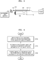
- FIGS. 5A and 5B are diagrams illustrating a method of obtaining position and movement direction information based on a movement of a biopsy needle 510 attached to an ultrasound probe 500, according to an embodiment.
- a guide cover 520 may be attached to one side of the ultrasound probe 500, and a biopsy needle 510 may be I enveloped by the guide cover 520.
- An EM sensor embedded in the biopsy needle 510 may detect the electromagnetic field generated by an electromagnetic field generator and generate position information based on the electromagnetic field.
- the position information may be transmitted to a tracker, and the tracker may generate 3D position coordinate values X R , Y R , and Z R of the first position P R of the EM sensor.
- the 3D position coordinate values X R , Y R , and Z R may be the initial position or the starting point of the biopsy needle 510.
- the first position P R may also reflect the location of the ultrasound probe 500.
- first position P R may also be the position of a first end 500-1 of the ultrasound probe 500.
- the first position P R may refer to a position of the biopsy needle 510 when it is retracted in the guide cover 520, and the 3D position coordinate values X R , Y R , and Z R of the first position P R may be equal to 3D position coordinate values of the first end 500-1 of the ultrasound probe 500.
- the biopsy apparatus may set the 3D position coordinate values X R , Y R , and Z R of the first position P R as a reference value and may store them in a memory.
- FIG. 5B illustrates an instance where an operator of the biopsy apparatus (e.g., a doctor) pushes the biopsy needle 510 to extend the biopsy needle 510 into the object.
- an operator of the biopsy apparatus e.g., a doctor
- the biopsy needle 510 may move to extend from the guide cover 520. After the movement, the EM sensor is now located at a second position P N .
- the second position P N may be different from the first position P R .
- 3D position coordinate values X N , Y N , and Z N of the second position P N may be different from the 3D position coordinate values X R , Y R , and Z R of the first position P R in FIG. 5A .
- the biopsy apparatus may store the 3D position coordinate values X N , Y N , and Z N of the second position P N in the memory.
- the biopsy needle 510 may be moved in a first direction Z 1 and a second direction Z 2 in the guide cover 520, based on operator manipulation.
- the first direction Z 1 may refer to the direction in which the biopsy needle 510 extends from the guide cover 520 and is inserted into the object.
- the second direction Z 2 may refer to the direction in which the biopsy needle 510 retracts into the guide cover 520 and is withdrawn from the object.
- the biopsy apparatus may recognize whether or not the biopsy needle 510 is moved, by determining that the second position P N and the first position P R have different position coordinate values. In addition, the biopsy apparatus may obtain a movement direction vector value of the biopsy needle 510 using the difference between the second position P N and the first position P R .
- the biopsy apparatus may determine the operation mode by (1) calculating the difference in value between the first position P R of the biopsy needle 510 and the moved second position P N and (2) calculating a dot-product between the direction vector value Z R at the first position P R and the direction vector value Z N at the moved second position P N .
- the biopsy apparatus may perform registration correction between ultrasound images and images of other modalities in the appropriate mode.
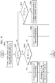
- FIG. 6 is a flowchart illustrating a method, performed by a biopsy apparatus, of determining an operation mode, registering images, and performing correction, based on a position and movement direction of a biopsy needle, according to an embodiment.
- the biopsy apparatus obtains changed position coordinate values and a changed direction vector value of the biopsy needle.
- An EM sensor embedded in the biopsy needle may detect the electromagnetic field generated by an electromagnetic field generator and may transmit 3D position coordinate values generated based on the electromagnetic field to the biopsy apparatus.
- the biopsy apparatus may obtain the 3D position coordinate values X R , Y R , and Z R of the first position P R of the biopsy needle 510 and the 3D position coordinate values X N , Y N , and Z N of the second position P N of the biopsy needle 510 when the biopsy needle 510 is moved by the operator (e.g., a doctor) to obtain a biopsy.
- the biopsy apparatus may also obtain the direction vector Z R at the first position P R and the direction vector Z N that correspond to the direction of the biopsy needle 510's movement.
- the direction vector Z N may indicate movements in the first direction Z 1 or the second direction Z 2 .
- the biopsy apparatus may recognize whether or not the biopsy needle has moved.
- the biopsy apparatus may calculate a distance between the 3D position coordinate values X R , Y R , and Z R of the first position P R and the 3D position coordinate values X N , Y N , and Z N of the second position P N .
- the biopsy apparatus may determine whether the biopsy needle 510 has been moved by using Inequality 1 below.
- may be the Euclidean distance between the first position P R and the second position P N .
- the value of ⁇ 1 may be a random positive number that is greater than 0 but is close to 0. If Inequality 1 indicates True, i.e., if the square of the Euclidean distance between the first position P R and the second position P N is greater than ⁇ 1, the biopsy apparatus may determine that the biopsy needle has been moved. On the other hand, if Inequality 1 indicates False, the biopsy apparatus may determine that the biopsy needle is not moved.
- the biopsy apparatus determines whether the movement direction of the biopsy needle is equal to the direction of the ultrasound probe.
- the direction of the ultrasound probe may be the direction vector Z R at the first position P R and the movement direction of the biopsy needle may be the direction vector Z N of the second position P N of the biopsy needle which are obtained in operation S610.
- the biopsy apparatus may recognize the movement direction of the biopsy needle by using Inequality 2 below. Z R ⁇ ⁇ Z N ⁇ > 1 ⁇ ⁇ 2
- a value of ⁇ 2 may be a predetermined positive number that is greater than 0 but is close to 0. If Inequality 2 indicates True, i.e., if the dot-product between the direction vector Z R at the first position P R and the direction vector Z N of the second position P N is greater than (1- ⁇ 2 ), it may mean that the biopsy needle is being inserted into the object. Because the biopsy needle can move only in the first direction or the second direction that is opposite to the first direction in the guide cover, when the dot-product between the direction vector Z R and the direction vector Z N is greater than (1- ⁇ 2 ), the biopsy apparatus may recognize that the movement direction of the biopsy needle indicates a direction in which the biopsy needle is being inserted into the object.
- the biopsy apparatus may recognize that the biopsy needle is being retracted into the guide cover.
- the biopsy apparatus may determine the operation mode to be the biopsy mode.
- the biopsy needle In the biopsy mode, the biopsy needle may be inserted into the object. That is, if both Inequality 1 in operation S620 and Inequality 2 in operation S630 indicate True, the biopsy apparatus may recognize that the biopsy needle is moved by the operator (e.g. a doctor) to extend into the object. Accordingly, the biopsy apparatus may determine the operation mode to be the biopsy mode.
- the biopsy apparatus performs correction on the images of other modalities the images of other modalities are paused at a point in time immediately prior to when the biopsy needle starts moving.
- the biopsy apparatus may display the images of other modalities that are registered with the ultrasound images.
- the ultrasound probe stops moving.
- apparatus of other modalities such as the CT apparatus or the MRI apparatus, may continue to move to follow the movement of the biopsy needle.
- the ultrasound imaging apparatus and the apparatuses of other modalities may be obtaining images from different areas of the object.
- the biopsy apparatus may pause the movement of the apparatuses so that still images at the first position P R are obtained by both the ultrasound imaging apparatus and the apparatuses of other modalities.
- the biopsy apparatus displays an alarm message or a confirmation message on a display.
- Inequality 1 indicates True in operation S620 and Inequality 2 indicates False in operation S630, i.e., when the biopsy needle is determined to have been moved but the movement direction is not towards the object, the biopsy apparatus may determine that the movement of the biopsy needle is wrong.
- the biopsy apparatus may output an error message or the alarm message to the display.
- the biopsy apparatus may output to the display a confirmation message asking the operator to check the movement direction of the biopsy needle.
- the biopsy apparatus determines whether the dot-product between the direction vector Z R at the first position P R and the direction vector Z N of the second position P N is 0. If so, the biopsy apparatus may determine that the operator did not move the biopsy needle.
- the biopsy apparatus determines the operation mode to be the image registration mode.
- the biopsy apparatus may determine that the biopsy needle may be bent or deformed in the guide cover. In this case, the biopsy apparatus may cease operation.
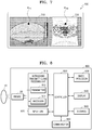
- FIG. 7 is a diagram illustrating image registration between an ultrasound image and an image of another modality, according to an embodiment.
- the display 700 of the biopsy apparatus may display both an ultrasound image 710 and an image of another modality 720.
- the image 720 may refer to, but is not limited to, a CT image, an MRI image, an X-ray image, etc.
- the image 720 may refer to a medical diagnostic image that is not an ultrasound image.
- the biopsy apparatus may perform registration between the ultrasound image 710 and the image 720.
- the biopsy apparatus may perform point-to-point registration where specific regions of the object are matched in both the ultrasound image 710 and the image of another modality 720. For example, as shown in FIG. 7 , a first point P 710 displayed on the ultrasound image 710 may correspond to a specific region of the object. That region may also be shown in the image of another modality 720 at second point P 720 .
- the point-to-point registration is well-known in the art to one of ordinary skill. Thus, detailed descriptions thereof are omitted here.
- FIG. 7 illustrates only the point-to-point registration
- the image registration performed by the biopsy apparatus is not limited to the point-to-point registration.
- the biopsy apparatus may perform the image registration between the ultrasound image 710 and the image 720 by using all known image registration methods in the art.
- the biopsy apparatus may perform correction on the image of another modality 720 so that the image 720 is paused at a point in time immediately prior to when the biopsy needle starts moving.
- the operator of the biopsy apparatus e.g., a doctor
- the ultrasound probe may not move, but the apparatus of the other modality (e.g. a CT apparatus) may continue to move to follow the biopsy needle.
- the biopsy apparatus may pause the image 720 at a point in time immediately prior to when the biopsy needle starts moving.
- FIG. 8 is a block diagram illustrating an ultrasound imaging apparatus 800 included in a biopsy apparatus, according to an embodiment.
- the ultrasound imaging apparatus 800 may include a probe 20, an ultrasound transmitting and receiving unit 810, a controller 820, an image processor 830, a display 840, a storage 850, a communicator 860, and an input unit 870.
- the ultrasound imaging apparatus 800 may be a cart-type ultrasound imaging apparatus or a portable-type ultrasound imaging apparatus.
- Examples of the portable-type ultrasound imaging apparatuses may include systems implemented with smartphones, laptop computers, personal digital assistants (PDAs), and tablet personal computers (PCs), each of which may include a probe and a software application.
- PDAs personal digital assistants
- PCs tablet personal computers
- the probe 20 may include a plurality of transducers.
- the plurality of transducers may transmit ultrasound signals to the object 10 in response to transmission signals from the transmitter 812.
- the plurality of transducers may receive ultrasound echo signals reflected from the object 10 and generate reception signals from the received echo signals.
- the probe 20 and the ultrasound imaging apparatus 800 integrated into one body, or the probe 20 may be a separate probe that is connected to the ultrasound imaging apparatus 800 via a wire or wirelessly.
- the ultrasound imaging apparatus 800 may include the probe 20 or a plurality of the probes 20.
- the controller 820 controls the transmitter 812 to generate the transmission signals to be transmitted to the plurality of transducers.
- the transmission signals may take into account the positions and focal points of the plurality of transducers in the probe 20.
- the controller 820 controls the receiver 814, which may perform analog-to-digital conversion of the reception signals from the probe 20, and then to generate ultrasound data.
- the image processor 830 generates ultrasound images by using the ultrasound data generated by the receiver 814.
- the display 840 may display the generated ultrasound images and various types of information processed by the ultrasound imaging apparatus 800.
- the ultrasound imaging apparatus 800 may include the display 840 or a plurality of the displays 840.
- the display 840 may be combined with a touch panel so that it is a touchscreen.
- the controller 820 may control the operations of the ultrasound imaging apparatus 800, and manage the signal flow between components in the ultrasound imaging apparatus 800.
- the controller 820 may include a memory to store programs or data for the operations of the ultrasound imaging apparatus 800, and a processor to process the programs or the data.
- the controller 820 may receive a control signal from the input unit 870, so that the operator of the ultrasound imaging apparatus 800 may control the ultrasound imaging apparatus 800 via the input unit 870.
- the ultrasound imaging apparatus 800 may include the communicator 860 and may be in communication with an external apparatus (e.g., servers, medical apparatuses, portable devices (smartphones, tablet PCs, wearable devices, etc.), or the like) via the communicator 860.
- an external apparatus e.g., servers, medical apparatuses, portable devices (smartphones, tablet PCs, wearable devices, etc.), or the like.
- the communicator 860 may include a component for communication with the external apparatus.
- the communicator 860 may include a short-range communication module, a wired communication module, a wireless communication module, etc.
- the communicator 860 may receive a control signal and data from the external apparatus and may deliver the received control signal to the controller 820, such that the controller 820 may control the ultrasound imaging apparatus 800 in response to the received control signal.
- the controller 820 may transmit a control signal to the external apparatus via the communicator 860, such that the external apparatus may be controlled in response to the control signal of the controller 820.
- the external apparatus may process data in response to a control signal transmitted from the controller 820 via the communicator 860.
- Programs for controlling the ultrasound imaging apparatus 800 may be installed in the external apparatus. These programs may include instructions for performing some or all operations of the controller 820.
- the programs may be preinstalled on the external apparatus, or the user of the external apparatus may download the programs from servers.
- the servers may include a recording medium having the program recorded thereon.
- the storage 850 may store various types of data or programs for driving and controlling the ultrasound imaging apparatus 800, such as ultrasound data, obtained ultrasound images, or the like.
- the input unit 870 may receive a user input of controlling the ultrasound imaging apparatus 800.
- the user input may include inputs generated by the manipulation of buttons, keypads, mice, trackballs, jog switches, knobs, touch inputs, voice inputs, motion inputs, bio-information inputs (for example, iris recognition or fingerprint recognition), etc.
- Examples of the ultrasound imaging apparatus 800 are described below with reference to FIG. 9A, 9B, and 9C .
- FIG. 9A, 9B, and 9C illustrate ultrasound imaging apparatuses 900a, 900b, and 900c, each including a biopsy apparatus.
- the ultrasound imaging apparatuses 900a and 900b may each include a main display 922 and a sub-display 924.
- One of the main display 922 and the sub-display 924 may be a touchscreen.
- the main display 922 and the sub-display 924 may display ultrasound images or various types of information processed by the ultrasound imaging apparatuses 900a and 900b.
- the main display 922 and the sub-display 924 when implemented as touchscreens, may provide graphical user interfaces (GUI) that allows the operator to enter inputs for controlling the ultrasound imaging apparatuses 900a and 900b.
- GUI graphical user interfaces
- the main display 922 may display ultrasound images
- the sub-display 924 may display a GUI control panel for controlling the ultrasound image.
- the ultrasound imaging apparatus 900b may further include a physical control panel 960 in addition to the main display 922 and the sub-display 924.
- the control panel 960 may include buttons, trackballs, jog switches, knobs, or the like, and may receive user input from the operator for controlling the ultrasound imaging apparatus 900b.
- the control panel 960 may include a time gain compensation (TGC) button 972, a freeze button 974, or the like.
- TGC button 972 is a button for setting TGC values for adjusting the depths of ultrasound images.
- the freeze button 974 allows the operator to pause the currently displayed ultrasound image.
- buttons, the trackballs, the jog switches, the knobs, or the like included in the control panel 960 may be provided as software user interface elements in a GUI displayed on the main display 922 or the sub-display 924.
- the ultrasound imaging apparatus 900c may be implemented as a portable-type ultrasound imaging apparatus 900c.
- the ultrasound imaging apparatus 900c may include a probe 20 and a body 930, and the probe 20 may be connected to one side of the body 930 via a wire. Alternatively, the probe 20 may be connected to the body 930 wirelessly.
- the body 930 may include a touchscreen 940.
- the touchscreen 940 may display ultrasound images, various types of information processed by the ultrasound imaging apparatus 900c, GUIs, or the like.
- Embodiments may be implemented through non-transitory computer-readable recording media having recorded thereon computer-executable instructions and data.
- the instructions may be program codes, and when the instructions are executed by a processor, the instructions may generate a preset program module to perform preset operations. Furthermore, when the instructions are executed by the processor, the instructions may perform specific operations according to the embodiments.
- a recording medium such as a CD ROM, a Digital Versatile Disc (DVD), a magnetic tape, a RAM, a floppy disk, a hard disk, or a magneto-optical disk or computer code downloaded over a network originally stored on a remote recording medium or a non-transitory machine readable medium and to be stored on a local recording medium, so that the methods described herein can be rendered via such software that is stored on the recording medium using a general purpose computer, or a special processor or in programmable or dedicated hardware, such as an ASIC or FPGA.
- a recording medium such as a CD ROM, a Digital Versatile Disc (DVD), a magnetic tape, a RAM, a floppy disk, a hard disk, or a magneto-optical disk or computer code downloaded over a network originally stored on a remote recording medium or a non-transitory machine readable medium and to be stored on a local recording medium, so that the methods described herein can be rendered via such software that is stored
- the computer, the processor, microprocessor controller or the programmable hardware include memory components, e.g., RAM, ROM, Flash, etc. that may store or receive software or computer code that when accessed and executed by the computer, processor or hardware implement the processing methods described herein.
- memory components e.g., RAM, ROM, Flash, etc. that may store or receive software or computer code that when accessed and executed by the computer, processor or hardware implement the processing methods described herein.
Landscapes
- Health & Medical Sciences (AREA)
- Life Sciences & Earth Sciences (AREA)
- Engineering & Computer Science (AREA)
- Surgery (AREA)
- Animal Behavior & Ethology (AREA)
- Pathology (AREA)
- Veterinary Medicine (AREA)
- Public Health (AREA)
- Biomedical Technology (AREA)
- Heart & Thoracic Surgery (AREA)
- Medical Informatics (AREA)
- Molecular Biology (AREA)
- General Health & Medical Sciences (AREA)
- Nuclear Medicine, Radiotherapy & Molecular Imaging (AREA)
- Physics & Mathematics (AREA)
- Biophysics (AREA)
- Radiology & Medical Imaging (AREA)
- Computer Vision & Pattern Recognition (AREA)
- Ultra Sonic Daignosis Equipment (AREA)
Applications Claiming Priority (1)
| Application Number | Priority Date | Filing Date | Title |
|---|---|---|---|
| KR1020160142147A KR101931747B1 (ko) | 2016-10-28 | 2016-10-28 | 생체 검사 장치 및 동작 방법 |
Publications (2)
| Publication Number | Publication Date |
|---|---|
| EP3315076A1 true EP3315076A1 (fr) | 2018-05-02 |
| EP3315076B1 EP3315076B1 (fr) | 2021-06-02 |
Family
ID=60190725
Family Applications (1)
| Application Number | Title | Priority Date | Filing Date |
|---|---|---|---|
| EP17198878.5A Active EP3315076B1 (fr) | 2016-10-28 | 2017-10-27 | Appareil de biopsie |
Country Status (3)
| Country | Link |
|---|---|
| US (1) | US11331086B2 (fr) |
| EP (1) | EP3315076B1 (fr) |
| KR (1) | KR101931747B1 (fr) |
Cited By (1)
| Publication number | Priority date | Publication date | Assignee | Title |
|---|---|---|---|---|
| CN116269768A (zh) * | 2023-05-22 | 2023-06-23 | 北京迈迪斯医疗技术有限公司 | 基于电磁定位的取卵系统 |
Families Citing this family (4)
| Publication number | Priority date | Publication date | Assignee | Title |
|---|---|---|---|---|
| KR102747176B1 (ko) | 2018-12-11 | 2024-12-27 | 삼성메디슨 주식회사 | 초음파 영상 장치, 그 제어 방법, 및 컴퓨터 프로그램 제품 |
| CN110946552B (zh) * | 2019-10-30 | 2022-04-08 | 南京航空航天大学 | 一种结合光谱和图像的宫颈癌前病变筛查方法 |
| CN119365135A (zh) | 2022-06-17 | 2025-01-24 | 波士顿科学医学有限公司 | 医疗装置位置感测组件 |
| KR102921912B1 (ko) * | 2022-09-20 | 2026-02-04 | 주식회사 덴티움 | 실시간 임플란트 식립 진행 가이드 방법 및 시스템 |
Citations (7)
| Publication number | Priority date | Publication date | Assignee | Title |
|---|---|---|---|---|
| US20070232882A1 (en) * | 2006-03-31 | 2007-10-04 | Glossop Neil D | System, Methods, and Instrumentation for Image Guided Prostate Treatment |
| WO2009153723A1 (fr) * | 2008-06-20 | 2009-12-23 | Koninklijke Philips Electronics, N.V. | Méthode et système permettant d'effectuer des biopsies |
| US20100081920A1 (en) * | 2008-09-29 | 2010-04-01 | Civco Medical Instruments Co., Inc. | Em tracking systems for use with ultrasound and other imaging modalities |
| WO2013111133A1 (fr) * | 2012-01-26 | 2013-08-01 | Uc-Care Ltd. | Système intégré destiné au traitement ciblé et procédés associés |
| US20130324841A1 (en) * | 2012-05-31 | 2013-12-05 | Ali Kamen | System and Method for Real-Time Ultrasound Guided Prostate Needle Biopsy Based on Biomechanical Model of the Prostate from Magnetic Resonance Imaging Data |
| KR20160089687A (ko) * | 2015-01-20 | 2016-07-28 | 삼성전자주식회사 | 휴대용 초음파 진단장치, 및 그 제어방법 |
| KR20160142147A (ko) | 2015-06-02 | 2016-12-12 | 주식회사 엘지화학 | 헤테로고리 화합물 및 이를 포함하는 유기 발광 소자 |
Family Cites Families (22)
| Publication number | Priority date | Publication date | Assignee | Title |
|---|---|---|---|---|
| EP1815796A4 (fr) * | 2004-11-17 | 2009-10-28 | Hitachi Medical Corp | Ultrasonographe et méthode d'affichage d'image par ultrason |
| KR20070110965A (ko) | 2006-05-16 | 2007-11-21 | 주식회사 메디슨 | 초음파 영상과 외부 의료영상의 합성 영상을디스플레이하기 위한 초음파 시스템 |
| KR100971417B1 (ko) * | 2006-10-17 | 2010-07-21 | 주식회사 메디슨 | 초음파 영상과 외부 의료영상의 합성 영상 상에 의료용바늘을 디스플레이하기 위한 초음파 시스템 |
| FR2920961B1 (fr) | 2007-09-18 | 2017-06-02 | Koelis | Systeme et procede d'imagerie et de localisation de ponctions sous echographie prostatique |
| US20100063400A1 (en) * | 2008-09-05 | 2010-03-11 | Anne Lindsay Hall | Method and apparatus for catheter guidance using a combination of ultrasound and x-ray imaging |
| US8556815B2 (en) * | 2009-05-20 | 2013-10-15 | Laurent Pelissier | Freehand ultrasound imaging systems and methods for guiding fine elongate instruments |
| RU2558521C2 (ru) | 2009-06-05 | 2015-08-10 | Кониклейке Филипс Электроникс, Н.В. | Система и способ интегрированной биопсии и лечения |
| US10264947B2 (en) * | 2010-08-20 | 2019-04-23 | Veran Medical Technologies, Inc. | Apparatus and method for airway registration and navigation |
| EP2478855B1 (fr) * | 2011-01-24 | 2016-09-07 | Samsung Medison Co., Ltd. | Dispositif de traitement |
| EP2478856B1 (fr) | 2011-01-24 | 2016-10-12 | Samsung Medison Co., Ltd. | Dispositif de traitement |
| KR101938807B1 (ko) | 2011-02-15 | 2019-04-10 | 가톨릭대학교 산학협력단 | 초음파 시술용 바늘의 위치 가이드 장치 |
| KR20130063790A (ko) | 2011-12-07 | 2013-06-17 | 한국과학기술원 | 초음파 프로브의 위치 및 방향 추정 시스템 및 방법 |
| JP2013118998A (ja) * | 2011-12-08 | 2013-06-17 | Toshiba Corp | 医用画像診断装置、超音波診断装置及びプログラム |
| WO2014156973A1 (fr) * | 2013-03-29 | 2014-10-02 | 日立アロカメディカル株式会社 | Procédé d'affichage d'alignement d'image et dispositif de diagnostic par ultrasons |
| WO2014199799A1 (fr) * | 2013-06-11 | 2014-12-18 | 株式会社 東芝 | Dispositif de diagnostic par ultrasons, et dispositif de diagnostic par imagerie médicale |
| WO2015039302A1 (fr) * | 2013-09-18 | 2015-03-26 | Shenzhen Mindray Bio-Medical Electronics Co., Ltd | Procédé et système pour une acquisition d'image ultrasonore guidée |
| CN106413565B (zh) * | 2013-12-20 | 2019-12-17 | 皇家飞利浦有限公司 | 自动超声波束操纵和探针伪影抑制 |
| JP6309282B2 (ja) * | 2014-01-22 | 2018-04-11 | キヤノンメディカルシステムズ株式会社 | 医用画像診断装置 |
| JP2015139576A (ja) | 2014-01-29 | 2015-08-03 | ジーイー・メディカル・システムズ・グローバル・テクノロジー・カンパニー・エルエルシー | 超音波診断装置及びプログラム |
| US20160151039A1 (en) * | 2014-11-28 | 2016-06-02 | Kabushiki Kaisha Toshiba | Ultrasound diagnosis apparatus |
| US11026750B2 (en) * | 2015-01-23 | 2021-06-08 | Queen's University At Kingston | Real-time surgical navigation |
| EP3282997B1 (fr) * | 2015-04-15 | 2021-06-16 | Mobius Imaging, LLC | Système robotique chirurgical et d'imagerie médicale intégré |
-
2016
- 2016-10-28 KR KR1020160142147A patent/KR101931747B1/ko active Active
-
2017
- 2017-10-27 EP EP17198878.5A patent/EP3315076B1/fr active Active
- 2017-10-27 US US15/795,566 patent/US11331086B2/en active Active
Patent Citations (7)
| Publication number | Priority date | Publication date | Assignee | Title |
|---|---|---|---|---|
| US20070232882A1 (en) * | 2006-03-31 | 2007-10-04 | Glossop Neil D | System, Methods, and Instrumentation for Image Guided Prostate Treatment |
| WO2009153723A1 (fr) * | 2008-06-20 | 2009-12-23 | Koninklijke Philips Electronics, N.V. | Méthode et système permettant d'effectuer des biopsies |
| US20100081920A1 (en) * | 2008-09-29 | 2010-04-01 | Civco Medical Instruments Co., Inc. | Em tracking systems for use with ultrasound and other imaging modalities |
| WO2013111133A1 (fr) * | 2012-01-26 | 2013-08-01 | Uc-Care Ltd. | Système intégré destiné au traitement ciblé et procédés associés |
| US20130324841A1 (en) * | 2012-05-31 | 2013-12-05 | Ali Kamen | System and Method for Real-Time Ultrasound Guided Prostate Needle Biopsy Based on Biomechanical Model of the Prostate from Magnetic Resonance Imaging Data |
| KR20160089687A (ko) * | 2015-01-20 | 2016-07-28 | 삼성전자주식회사 | 휴대용 초음파 진단장치, 및 그 제어방법 |
| KR20160142147A (ko) | 2015-06-02 | 2016-12-12 | 주식회사 엘지화학 | 헤테로고리 화합물 및 이를 포함하는 유기 발광 소자 |
Cited By (2)
| Publication number | Priority date | Publication date | Assignee | Title |
|---|---|---|---|---|
| CN116269768A (zh) * | 2023-05-22 | 2023-06-23 | 北京迈迪斯医疗技术有限公司 | 基于电磁定位的取卵系统 |
| CN116269768B (zh) * | 2023-05-22 | 2023-07-21 | 北京迈迪斯医疗技术有限公司 | 基于电磁定位的取卵系统 |
Also Published As
| Publication number | Publication date |
|---|---|
| EP3315076B1 (fr) | 2021-06-02 |
| KR20180046675A (ko) | 2018-05-09 |
| US20180116643A1 (en) | 2018-05-03 |
| KR101931747B1 (ko) | 2019-03-13 |
| US11331086B2 (en) | 2022-05-17 |
Similar Documents
| Publication | Publication Date | Title |
|---|---|---|
| EP3315076B1 (fr) | Appareil de biopsie | |
| US7074185B2 (en) | Ultrasonic diagnostic apparatus, ultrasonic probe and navigation method for acquisition of ultrasonic image | |
| CN106659474B (zh) | 用于自诊断和远程诊断的超声诊断设备以及操作超声诊断设备的方法 | |
| US10695032B2 (en) | Medical image display apparatus and method therefor | |
| US11766236B2 (en) | Method and apparatus for displaying ultrasound image providing orientation of fetus and computer program product | |
| US10788964B1 (en) | Method and system for presenting function data associated with a user input device at a main display in response to a presence signal provided via the user input device | |
| CN106983521B (zh) | 超声成像设备 | |
| US11419574B2 (en) | Ultrasound imaging apparatus, method of controlling the same, and computer program product | |
| US20150065867A1 (en) | Ultrasound diagnostic apparatus and method of operating the same | |
| EP3292820A1 (fr) | Appareil d'imagerie ultrasonore et son procédé de commande | |
| US20180228473A1 (en) | Ultrasonic diagnostic apparatus and control method of ultrasonic diagnostic apparatus | |
| EP3666196B1 (fr) | Appareil d'imagerie à ultrasons et produit programme informatique | |
| KR102593439B1 (ko) | 초음파 진단 장치의 제어 방법 및 초음파 진단 장치 | |
| US20160066887A1 (en) | Image indicator provision in ultrasound system | |
| US11779308B2 (en) | Ultrasound diagnosis apparatus and method of managing ultrasound image obtained thereby | |
| US11439366B2 (en) | Image processing apparatus, ultrasound diagnosis system, operation method of image processing apparatus, and computer-readable recording medium | |
| US10470824B2 (en) | Imaging apparatus and interventional instrument event mapper | |
| KR102852593B1 (ko) | 초음파 영상 장치, 그 제어 방법, 및 컴퓨터 프로그램 | |
| EP3656312B1 (fr) | Appareil d'imagerie ultrasonore et procédé de commande correspondant | |
| US11607191B2 (en) | Ultrasound diagnosis apparatus and method of acquiring shear wave elasticity data with respect to object cross-section in 3D |
Legal Events
| Date | Code | Title | Description |
|---|---|---|---|
| PUAI | Public reference made under article 153(3) epc to a published international application that has entered the european phase |
Free format text: ORIGINAL CODE: 0009012 |
|
| STAA | Information on the status of an ep patent application or granted ep patent |
Free format text: STATUS: REQUEST FOR EXAMINATION WAS MADE |
|
| 17P | Request for examination filed |
Effective date: 20171027 |
|
| AK | Designated contracting states |
Kind code of ref document: A1 Designated state(s): AL AT BE BG CH CY CZ DE DK EE ES FI FR GB GR HR HU IE IS IT LI LT LU LV MC MK MT NL NO PL PT RO RS SE SI SK SM TR |
|
| AX | Request for extension of the european patent |
Extension state: BA ME |
|
| RAP1 | Party data changed (applicant data changed or rights of an application transferred) |
Owner name: SAMSUNG MEDISON CO., LTD. |
|
| STAA | Information on the status of an ep patent application or granted ep patent |
Free format text: STATUS: EXAMINATION IS IN PROGRESS |
|
| 17Q | First examination report despatched |
Effective date: 20190709 |
|
| GRAP | Despatch of communication of intention to grant a patent |
Free format text: ORIGINAL CODE: EPIDOSNIGR1 |
|
| STAA | Information on the status of an ep patent application or granted ep patent |
Free format text: STATUS: GRANT OF PATENT IS INTENDED |
|
| INTG | Intention to grant announced |
Effective date: 20201216 |
|
| GRAS | Grant fee paid |
Free format text: ORIGINAL CODE: EPIDOSNIGR3 |
|
| GRAA | (expected) grant |
Free format text: ORIGINAL CODE: 0009210 |
|
| STAA | Information on the status of an ep patent application or granted ep patent |
Free format text: STATUS: THE PATENT HAS BEEN GRANTED |
|
| REG | Reference to a national code |
Ref country code: CH Ref legal event code: EP |
|
| AK | Designated contracting states |
Kind code of ref document: B1 Designated state(s): AL AT BE BG CH CY CZ DE DK EE ES FI FR GB GR HR HU IE IS IT LI LT LU LV MC MK MT NL NO PL PT RO RS SE SI SK SM TR |
|
| REG | Reference to a national code |
Ref country code: GB Ref legal event code: FG4D |
|
| REG | Reference to a national code |
Ref country code: AT Ref legal event code: REF Ref document number: 1397695 Country of ref document: AT Kind code of ref document: T Effective date: 20210615 |
|
| REG | Reference to a national code |
Ref country code: IE Ref legal event code: FG4D |
|
| REG | Reference to a national code |
Ref country code: DE Ref legal event code: R096 Ref document number: 602017039586 Country of ref document: DE |
|
| REG | Reference to a national code |
Ref country code: LT Ref legal event code: MG9D |
|
| PG25 | Lapsed in a contracting state [announced via postgrant information from national office to epo] |
Ref country code: FI Free format text: LAPSE BECAUSE OF FAILURE TO SUBMIT A TRANSLATION OF THE DESCRIPTION OR TO PAY THE FEE WITHIN THE PRESCRIBED TIME-LIMIT Effective date: 20210602 Ref country code: LT Free format text: LAPSE BECAUSE OF FAILURE TO SUBMIT A TRANSLATION OF THE DESCRIPTION OR TO PAY THE FEE WITHIN THE PRESCRIBED TIME-LIMIT Effective date: 20210602 Ref country code: BG Free format text: LAPSE BECAUSE OF FAILURE TO SUBMIT A TRANSLATION OF THE DESCRIPTION OR TO PAY THE FEE WITHIN THE PRESCRIBED TIME-LIMIT Effective date: 20210902 Ref country code: HR Free format text: LAPSE BECAUSE OF FAILURE TO SUBMIT A TRANSLATION OF THE DESCRIPTION OR TO PAY THE FEE WITHIN THE PRESCRIBED TIME-LIMIT Effective date: 20210602 |
|
| REG | Reference to a national code |
Ref country code: NL Ref legal event code: MP Effective date: 20210602 |
|
| REG | Reference to a national code |
Ref country code: AT Ref legal event code: MK05 Ref document number: 1397695 Country of ref document: AT Kind code of ref document: T Effective date: 20210602 |
|
| PG25 | Lapsed in a contracting state [announced via postgrant information from national office to epo] |
Ref country code: LV Free format text: LAPSE BECAUSE OF FAILURE TO SUBMIT A TRANSLATION OF THE DESCRIPTION OR TO PAY THE FEE WITHIN THE PRESCRIBED TIME-LIMIT Effective date: 20210602 Ref country code: GR Free format text: LAPSE BECAUSE OF FAILURE TO SUBMIT A TRANSLATION OF THE DESCRIPTION OR TO PAY THE FEE WITHIN THE PRESCRIBED TIME-LIMIT Effective date: 20210903 Ref country code: PL Free format text: LAPSE BECAUSE OF FAILURE TO SUBMIT A TRANSLATION OF THE DESCRIPTION OR TO PAY THE FEE WITHIN THE PRESCRIBED TIME-LIMIT Effective date: 20210602 Ref country code: NO Free format text: LAPSE BECAUSE OF FAILURE TO SUBMIT A TRANSLATION OF THE DESCRIPTION OR TO PAY THE FEE WITHIN THE PRESCRIBED TIME-LIMIT Effective date: 20210902 Ref country code: SE Free format text: LAPSE BECAUSE OF FAILURE TO SUBMIT A TRANSLATION OF THE DESCRIPTION OR TO PAY THE FEE WITHIN THE PRESCRIBED TIME-LIMIT Effective date: 20210602 Ref country code: RS Free format text: LAPSE BECAUSE OF FAILURE TO SUBMIT A TRANSLATION OF THE DESCRIPTION OR TO PAY THE FEE WITHIN THE PRESCRIBED TIME-LIMIT Effective date: 20210602 |
|
| PG25 | Lapsed in a contracting state [announced via postgrant information from national office to epo] |
Ref country code: SM Free format text: LAPSE BECAUSE OF FAILURE TO SUBMIT A TRANSLATION OF THE DESCRIPTION OR TO PAY THE FEE WITHIN THE PRESCRIBED TIME-LIMIT Effective date: 20210602 Ref country code: SK Free format text: LAPSE BECAUSE OF FAILURE TO SUBMIT A TRANSLATION OF THE DESCRIPTION OR TO PAY THE FEE WITHIN THE PRESCRIBED TIME-LIMIT Effective date: 20210602 Ref country code: EE Free format text: LAPSE BECAUSE OF FAILURE TO SUBMIT A TRANSLATION OF THE DESCRIPTION OR TO PAY THE FEE WITHIN THE PRESCRIBED TIME-LIMIT Effective date: 20210602 Ref country code: CZ Free format text: LAPSE BECAUSE OF FAILURE TO SUBMIT A TRANSLATION OF THE DESCRIPTION OR TO PAY THE FEE WITHIN THE PRESCRIBED TIME-LIMIT Effective date: 20210602 Ref country code: AT Free format text: LAPSE BECAUSE OF FAILURE TO SUBMIT A TRANSLATION OF THE DESCRIPTION OR TO PAY THE FEE WITHIN THE PRESCRIBED TIME-LIMIT Effective date: 20210602 Ref country code: PT Free format text: LAPSE BECAUSE OF FAILURE TO SUBMIT A TRANSLATION OF THE DESCRIPTION OR TO PAY THE FEE WITHIN THE PRESCRIBED TIME-LIMIT Effective date: 20211004 Ref country code: NL Free format text: LAPSE BECAUSE OF FAILURE TO SUBMIT A TRANSLATION OF THE DESCRIPTION OR TO PAY THE FEE WITHIN THE PRESCRIBED TIME-LIMIT Effective date: 20210602 Ref country code: RO Free format text: LAPSE BECAUSE OF FAILURE TO SUBMIT A TRANSLATION OF THE DESCRIPTION OR TO PAY THE FEE WITHIN THE PRESCRIBED TIME-LIMIT Effective date: 20210602 Ref country code: ES Free format text: LAPSE BECAUSE OF FAILURE TO SUBMIT A TRANSLATION OF THE DESCRIPTION OR TO PAY THE FEE WITHIN THE PRESCRIBED TIME-LIMIT Effective date: 20210602 |
|
| REG | Reference to a national code |
Ref country code: DE Ref legal event code: R097 Ref document number: 602017039586 Country of ref document: DE |
|
| PLBE | No opposition filed within time limit |
Free format text: ORIGINAL CODE: 0009261 |
|
| STAA | Information on the status of an ep patent application or granted ep patent |
Free format text: STATUS: NO OPPOSITION FILED WITHIN TIME LIMIT |
|
| PG25 | Lapsed in a contracting state [announced via postgrant information from national office to epo] |
Ref country code: DK Free format text: LAPSE BECAUSE OF FAILURE TO SUBMIT A TRANSLATION OF THE DESCRIPTION OR TO PAY THE FEE WITHIN THE PRESCRIBED TIME-LIMIT Effective date: 20210602 |
|
| 26N | No opposition filed |
Effective date: 20220303 |
|
| PG25 | Lapsed in a contracting state [announced via postgrant information from national office to epo] |
Ref country code: AL Free format text: LAPSE BECAUSE OF FAILURE TO SUBMIT A TRANSLATION OF THE DESCRIPTION OR TO PAY THE FEE WITHIN THE PRESCRIBED TIME-LIMIT Effective date: 20210602 |
|
| REG | Reference to a national code |
Ref country code: CH Ref legal event code: PL |
|
| REG | Reference to a national code |
Ref country code: BE Ref legal event code: MM Effective date: 20211031 |
|
| GBPC | Gb: european patent ceased through non-payment of renewal fee |
Effective date: 20211027 |
|
| PG25 | Lapsed in a contracting state [announced via postgrant information from national office to epo] |
Ref country code: MC Free format text: LAPSE BECAUSE OF FAILURE TO SUBMIT A TRANSLATION OF THE DESCRIPTION OR TO PAY THE FEE WITHIN THE PRESCRIBED TIME-LIMIT Effective date: 20210602 |
|
| PG25 | Lapsed in a contracting state [announced via postgrant information from national office to epo] |
Ref country code: LU Free format text: LAPSE BECAUSE OF NON-PAYMENT OF DUE FEES Effective date: 20211027 Ref country code: GB Free format text: LAPSE BECAUSE OF NON-PAYMENT OF DUE FEES Effective date: 20211027 Ref country code: BE Free format text: LAPSE BECAUSE OF NON-PAYMENT OF DUE FEES Effective date: 20211031 |
|
| PG25 | Lapsed in a contracting state [announced via postgrant information from national office to epo] |
Ref country code: LI Free format text: LAPSE BECAUSE OF NON-PAYMENT OF DUE FEES Effective date: 20211031 Ref country code: CH Free format text: LAPSE BECAUSE OF NON-PAYMENT OF DUE FEES Effective date: 20211031 |
|
| PG25 | Lapsed in a contracting state [announced via postgrant information from national office to epo] |
Ref country code: IE Free format text: LAPSE BECAUSE OF NON-PAYMENT OF DUE FEES Effective date: 20211027 |
|
| PG25 | Lapsed in a contracting state [announced via postgrant information from national office to epo] |
Ref country code: HU Free format text: LAPSE BECAUSE OF FAILURE TO SUBMIT A TRANSLATION OF THE DESCRIPTION OR TO PAY THE FEE WITHIN THE PRESCRIBED TIME-LIMIT; INVALID AB INITIO Effective date: 20171027 |
|
| PG25 | Lapsed in a contracting state [announced via postgrant information from national office to epo] |
Ref country code: CY Free format text: LAPSE BECAUSE OF FAILURE TO SUBMIT A TRANSLATION OF THE DESCRIPTION OR TO PAY THE FEE WITHIN THE PRESCRIBED TIME-LIMIT Effective date: 20210602 |
|
| PG25 | Lapsed in a contracting state [announced via postgrant information from national office to epo] |
Ref country code: MK Free format text: LAPSE BECAUSE OF FAILURE TO SUBMIT A TRANSLATION OF THE DESCRIPTION OR TO PAY THE FEE WITHIN THE PRESCRIBED TIME-LIMIT Effective date: 20210602 |
|
| PG25 | Lapsed in a contracting state [announced via postgrant information from national office to epo] |
Ref country code: TR Free format text: LAPSE BECAUSE OF FAILURE TO SUBMIT A TRANSLATION OF THE DESCRIPTION OR TO PAY THE FEE WITHIN THE PRESCRIBED TIME-LIMIT Effective date: 20210602 |
|
| PG25 | Lapsed in a contracting state [announced via postgrant information from national office to epo] |
Ref country code: MT Free format text: LAPSE BECAUSE OF FAILURE TO SUBMIT A TRANSLATION OF THE DESCRIPTION OR TO PAY THE FEE WITHIN THE PRESCRIBED TIME-LIMIT Effective date: 20210602 |
|
| PGFP | Annual fee paid to national office [announced via postgrant information from national office to epo] |
Ref country code: IT Payment date: 20250909 Year of fee payment: 9 |
|
| PGFP | Annual fee paid to national office [announced via postgrant information from national office to epo] |
Ref country code: FR Payment date: 20250909 Year of fee payment: 9 |
|
| PGFP | Annual fee paid to national office [announced via postgrant information from national office to epo] |
Ref country code: DE Payment date: 20250908 Year of fee payment: 9 |