EP3315330B1 - Vorrichtung zur erkennung eines reifenzustandes - Google Patents
Vorrichtung zur erkennung eines reifenzustandes Download PDFInfo
- Publication number
- EP3315330B1 EP3315330B1 EP16817552.9A EP16817552A EP3315330B1 EP 3315330 B1 EP3315330 B1 EP 3315330B1 EP 16817552 A EP16817552 A EP 16817552A EP 3315330 B1 EP3315330 B1 EP 3315330B1
- Authority
- EP
- European Patent Office
- Prior art keywords
- detection device
- state
- condition detection
- tire
- tire condition
- Prior art date
- Legal status (The legal status is an assumption and is not a legal conclusion. Google has not performed a legal analysis and makes no representation as to the accuracy of the status listed.)
- Active
Links
Images


Classifications
-
- B—PERFORMING OPERATIONS; TRANSPORTING
- B60—VEHICLES IN GENERAL
- B60C—VEHICLE TYRES; TYRE INFLATION; TYRE CHANGING; CONNECTING VALVES TO INFLATABLE ELASTIC BODIES IN GENERAL; DEVICES OR ARRANGEMENTS RELATED TO TYRES
- B60C23/00—Devices for measuring, signalling, controlling, or distributing tyre pressure or temperature, specially adapted for mounting on vehicles; Arrangement of tyre inflating devices on vehicles, e.g. of pumps or of tanks; Tyre cooling arrangements
- B60C23/02—Signalling devices actuated by tyre pressure
- B60C23/04—Signalling devices actuated by tyre pressure mounted on the wheel or tyre
- B60C23/0408—Signalling devices actuated by tyre pressure mounted on the wheel or tyre transmitting the signals by non-mechanical means from the wheel or tyre to a vehicle body mounted receiver
- B60C23/0422—Signalling devices actuated by tyre pressure mounted on the wheel or tyre transmitting the signals by non-mechanical means from the wheel or tyre to a vehicle body mounted receiver characterised by the type of signal transmission means
- B60C23/0433—Radio signals
- B60C23/0447—Wheel or tyre mounted circuits
- B60C23/0454—Means for changing operation mode, e.g. sleep mode, factory mode or energy save mode
-
- B—PERFORMING OPERATIONS; TRANSPORTING
- B60—VEHICLES IN GENERAL
- B60C—VEHICLE TYRES; TYRE INFLATION; TYRE CHANGING; CONNECTING VALVES TO INFLATABLE ELASTIC BODIES IN GENERAL; DEVICES OR ARRANGEMENTS RELATED TO TYRES
- B60C23/00—Devices for measuring, signalling, controlling, or distributing tyre pressure or temperature, specially adapted for mounting on vehicles; Arrangement of tyre inflating devices on vehicles, e.g. of pumps or of tanks; Tyre cooling arrangements
- B60C23/02—Signalling devices actuated by tyre pressure
- B60C23/04—Signalling devices actuated by tyre pressure mounted on the wheel or tyre
-
- G—PHYSICS
- G01—MEASURING; TESTING
- G01L—MEASURING FORCE, STRESS, TORQUE, WORK, MECHANICAL POWER, MECHANICAL EFFICIENCY, OR FLUID PRESSURE
- G01L17/00—Devices or apparatus for measuring tyre pressure or the pressure in other inflated bodies
-
- H—ELECTRICITY
- H04—ELECTRIC COMMUNICATION TECHNIQUE
- H04B—TRANSMISSION
- H04B1/00—Details of transmission systems, not covered by a single one of groups H04B3/00 - H04B13/00; Details of transmission systems not characterised by the medium used for transmission
- H04B1/38—Transceivers, i.e. devices in which transmitter and receiver form a structural unit and in which at least one part is used for functions of transmitting and receiving
- H04B1/40—Circuits
- H04B1/401—Circuits for selecting or indicating operating mode
Definitions
- the present invention relates to a tire condition detection device.
- Patent Document 1 discloses one example of a tire condition monitoring apparatus installed in a vehicle equipped with wheel assemblies.
- the tire condition monitoring apparatus of Patent Document 1 includes a receiver and tire condition detection devices, which are respectively installed in the wheel assemblies.
- Each tire condition detection device includes a condition detecting section that detects the condition of the tire and a transmitting section that transmits information indicating the condition of the tire detected by the condition detecting section to the receiver.
- the transmitting section is driven by the battery of the tire condition detection device.
- the receiver receives the information transmitted from the tire condition detection devices in the wheel assemblies and monitors the condition of each tire.
- Patent Document 1 Japanese Laid-Open Patent Publication No. 2014-91344
- Patent Document 2 WO 02/07993 A2 relates as prior art to a tire condition detection device configured to be installed in a tire of each wheel assembly of a vehicle.
- the device comprising: a condition detecting section configured to detect a condition of the tire; a transmitting section configured to wirelessly transmit information detected by the condition detecting section; a receiving section configured to be capable of receiving information wirelessly transmitted from an external device; a control section configured to control the transmitting section and the receiving section, wherein the control section is further configured to be capable of switching a state of the tire condition detection device between a responsive state (awake) and a non-responsive state (sleep).
- a tire condition detection device has not only a condition detection (measurement) function of obtaining the condition inside the tire and a function of transmitting the detected information to the receiver, but also a reception function of determining the timing of measurement and transmission from the outside.
- the reception function of a tire condition detection device is used, for example, when inspecting whether the tire condition detection device is operating properly at a factory or a dealer, when checking whether the tire air pressure is adequate at a factory or a dealer, and when registering the ID of the tire condition detection device attached to the vehicle to the receiver.
- the reception function can be used for wireless writing to update the software of the tire condition detection device.
- a tire condition detection device configured to be installed in a tire of each wheel assembly of a vehicle.
- the device includes a condition detecting section configured to detect a condition of the tire, a transmitting section configured to wirelessly transmit information detected by the condition detecting section, a receiving section configured to be capable of receiving information wirelessly transmitted from an external device, a control section configured to control the transmitting section and the receiving section, and a battery, which is a power source for the tire condition detection device.
- the control section is configured to be capable of switching a state of the tire condition detection device between a responsive state and a non-responsive state.
- the receiving section In the responsive state, the receiving section is maintained in a standby state, in which the receiving section is capable of receiving the information wirelessly transmitted from the external device.
- the control section performs a reception response when the information is received.
- the receiving section In the non-responsive state, the receiving section does not receive the information.
- the tire condition detection device does not receive wireless signals in the non-responsive state. Therefore, since the reception response is not performed in the non-responsive state, the power consumed for the reception response and the power consumed for receiving wireless transmission are reduced as compared with that in the responsive state. Since the tire condition detection device can be switched between the responsive state and the non-responsive state, the power consumption is reduced and the battery life is extended as compared with the case in which the tire condition detection device is always maintained in the responsive state.
- a tire condition detection device configured to be installed in a tire of each wheel assembly of a vehicle.
- the device includes a condition detecting section configured to detect a condition of the tire, a transmitting section configured to wirelessly transmit information detected by the condition detecting section, a receiving section configured to be capable of receiving information wirelessly transmitted from an external device, a control section configured to control the transmitting section and the receiving section, and a battery, which is a power source for the tire condition detection device.
- the control section is configured to be capable of switching a state of the tire condition detection device between a responsive state and a non-responsive state.
- the receiving section In the responsive state, the receiving section is maintained in a standby state, in which the receiving section is capable of receiving the information wirelessly transmitted from the external device.
- the control section performs a reception response when the information is received.
- the reception response In the non-responsive state, the reception response is harder to perform than in the responsive state regardless of whether the receiving section is maintained in the standby state.
- the reception response is less likely to be performed in the non-responsive state than in the responsive state
- the power consumed for the reception response and the power consumed for receiving wireless transmission are reduced as compared with that in the responsive state. Since the tire condition detection device can be switched between the responsive state and the non-responsive state, the power consumption is reduced and the battery life is extended as compared with the case in which the tire condition detection device is always maintained in the responsive state.
- the above-described tire condition detection devices may be configured such that, when the receiving section has received the same information from the external device multiple times or when the receiving section has continually received the information from the external device, the control section switches the state of the tire condition detection device from the responsive state to the non-responsive state.
- the receiving section may erroneously receive, for example, the wireless power outputted by the charging facility for charging electric vehicles or wireless information for detecting vehicles outputted in parking lots.
- the tire condition detection device may continue performing the erroneous reception and the accompanying operations (for example, transmission) during the stopped state of the vehicle. This may cause the tire condition detection device to consume significantly more power than it would maintain the standby state of the receiving section.
- the tire condition detection device When receiving information from an external device while being in the responsive state, the tire condition detection device performs a reception response (for example, responsive transmission).
- a reception response for example, responsive transmission
- the external device that has transmitted the information is an external device designed to transmit information to the tire condition detection device (an intended external device)
- the external device stops transmitting information when it receives the responsive transmission of the tire condition detection device or when a predetermined time has elapsed, so that the external device will semipermanently refrain from providing a response command to the tire condition detection device.
- the external device that has transmitted the information is an unintended external device, the external device continues wireless transmission regardless of a response of the tire condition detection device.
- the above-described tire condition detection devices may be configured such that the condition detecting section includes a sensor that detects traveling/stopping of the vehicle, and the control section is configured to switch the state of the tire condition detection device from the non-responsive state to the responsive state when traveling of the vehicle is detected.
- the state of the tire condition detection device in a case in which the state of the tire condition detection device is switched from the responsive state to the non-responsive state at an erroneous reception of information from an unintended external device, if it is detected that it is no longer the state of continual erroneous reception of external signals, that is, if traveling of the vehicle is detected, the state of the tire condition detection device is returned to the responsive state.
- the inclusion of such control allows the tire condition detection device to be switched to the responsive state in response to traveling of the vehicle.
- the tire condition can be checked with an external device at a dealer or the like.
- the above-described tire condition detection devices may be configured such that the condition detecting section includes a pressure sensor that detects an air pressure of the tire, and the control section switches the state of the tire condition detection device from the non-responsive state to the responsive state when the air pressure detected by the pressure sensor has changed by an amount greater than a change threshold or when the air pressure detected by the pressure sensor becomes lower than or equal to a low-pressure threshold.
- This configuration is designed to be used in an inspection at a dealer. Specifically, when the tire condition detection device detects a change in the tire air pressure or a low pressure, in other words, when the operator removes the tire air pressure from the valve, the state of the tire condition detection device is switched from the non-responsive state to the responsive state.
- a tire condition detection device configured to be installed in a tire of each wheel assembly of a vehicle.
- the device includes a condition detecting section configured to detect a condition of the tire, a transmitting section configured to wirelessly transmit information detected by the condition detecting section, a receiving section configured to be capable of receiving information wirelessly transmitted from an external device, a control section configured to control the transmitting section and the receiving section, and a battery, which is a power source for the tire condition detection device.
- the control section is configured switch a state of the tire condition detection device between a bidirectional communication state and a unidirectional communication state.
- the transmitting section is caused to perform wireless transmission, and the receiving section is maintained in a standby state, in which the receiving section is capable of receiving the information wirelessly transmitted from the external device.
- the standby state of the receiving section is maintained less frequently than in the bidirectional communication state, and consequently transmission is performed unilaterally.
- the standby state of the receiving section is maintained less frequently in the unidirectional communication state than in the bidirectional communication state.
- the power consumption for maintaining the receiving section in the standby state is reduced as compared to the bidirectional communication state. Therefore, as compared to the case in which the tire condition detection device is maintained in the bidirectional communication state even when information is not transmitted from an external device, the power consumption for maintaining the receiving section in the standby state, in which the receiving section is capable of receiving information from the external device, is reduced.
- the receiving section receives signals less frequently in the unidirectional communication state, the power consumption for erroneous reception and the associated operation (for example, transmission) is also reduced. These contents extend the life of the battery.
- the above-described tire condition detection device may be configured such that the condition detecting section includes a pressure sensor that detects an air pressure of the tire, and the control section is configured to switch the state of the tire condition detection device from the bidirectional communication state to the unidirectional communication state when a state in which the air pressure detected by the pressure sensor exceeds a low-pressure threshold has continued for a predetermined time or a longer period.
- the state of the tire condition detection device is switched from the bidirectional communication state to the unidirectional communication state.
- the low-pressure threshold is set to 200 kPa
- the tire air pressure exceeds 200 kPa
- the time for completion of inspection a predetermined time
- the state of the tire condition detection device is switched to the unidirectional communication state. This reduces the consumption of the power of the battery and extends the life of the battery.
- the above-described tire condition detection device may be configured such that the condition detecting section includes a pressure sensor that detects an air pressure of the tire, and the control section switches the state of the tire condition detection device from the unidirectional communication state to the bidirectional communication state when the air pressure detected by the pressure sensor has changed by an amount greater than a change threshold or when the air pressure detected by the pressure sensor becomes lower than or equal to a low-pressure threshold.
- This configuration is designed to be used in an inspection at a dealer. Specifically, when the tire condition detection device detects a change in the tire air pressure or a low pressure, in other words, when the operator removes the tire air pressure from the valve, the state of the tire condition detection device is switched to the bidirectional communication state.
- the present invention extends the life of the battery.
- a tire condition detection device according to a first embodiment will now be described.
- a vehicle 10 is equipped with a tire condition monitoring apparatus 20.
- the tire condition monitoring apparatus 20 includes four tire condition detection devices 21 and a receiver 30.
- Each tire condition detection device 21 is attached to one of four wheel assemblies 11.
- the receiver 30 is mounted in the body of the vehicle 10.
- Each wheel assembly 11 includes a wheel 12 and a tire 13 attached to the wheel 12.
- Each tire condition detection device 21 is installed so as to be located in the internal space of the tire 13.
- Each tire condition detection device 21 detects the corresponding tire condition (tire air pressure and the temperature inside the tire) and wirelessly transmits information including data indicating the detected tire condition.
- each tire condition detection device 21 includes a pressure sensor 22, a temperature sensor 23, an acceleration sensor 24, a controller 25 as a control section, a transmission circuit 26 as a transmitting section, a reception circuit 29 as a receiving section, and a battery 27 serving as a power source for the tire condition detection device 21.
- the controller 25 is configured to comprehensively control the operation of the tire condition detection device 21.
- the pressure sensor 22 detects the pressure in the associated tire 13 (tire air pressure).
- the temperature sensor 23 detects the temperature in the associated tire 13 (tire internal temperature).
- the acceleration sensor 24 detects acceleration (centrifugal force) acting on itself.
- the controller 25 obtains, at an adequate obtainment frequency, the tire pressure detected by the pressure sensor 22, the tire internal temperature detected by the temperature sensor 23, and the acceleration of the tire condition detection device 21 detected by the acceleration sensor 24.
- the adequate frequency is determined by factors such as the maximum capacity of the battery 27, the desired frequency of monitoring, and the like.
- the pressure sensor 22, the temperature sensor 23, and the acceleration sensor 24 constitute a condition detecting section and are configured to detect the condition of the tire 13.
- the controller 25 is configured by circuitry such as a microcomputer, that is, a processor.
- the controller 25 is configured to perform various kinds of control as will be described below. That is, the controller 25 is programmed to perform various kinds of control.
- an ID code is registered, which is identification information unique to each tire condition detection device 21.
- the ID code is information used to identify each tire condition detection device 21 at the receiver 30.
- the controller 25 outputs data containing the tire air pressure data, the tire internal temperature data, and the ID code to the transmission circuit 26.
- the transmission circuit 26 is configured to wirelessly transmit information including data from the controller 25 via an antenna (not shown).
- the information transmitted from the transmission circuit 26 is delivered as a radio frequency (RF) signal (for example, 315 MHz band or 434 MHz band signal).
- RF radio frequency
- the information from an external device received by the reception circuit 29 can be received as a low frequency (LF) signal (for example, 125 kHz band signal) via an antenna (not shown).
- LF low frequency
- an external device that is designed to transmit information to the tire condition detection device 21 (an intended external device) is, for example, a trigger device.
- a wireless signal transmitted from the external device includes a state switching command, measurement for inspection, responsive transmission command, wireless write command used for software update, wireless write information, and the like.
- the controller 25 determines that the vehicle 10 is traveling when the acceleration (centrifugal force) detected by the acceleration sensor 24 exceeds a travel determination threshold. That is, traveling/stopping of the vehicle 10 is detected based on whether the acceleration detected by the acceleration sensor 24 exceeds the threshold for travel determination.
- the acceleration acting on the acceleration sensor 24 increases as the speed of the vehicle 10 increases.
- the receiver 30 includes a receiver controller 31 and a reception circuit 32.
- the receiver controller 31 of the receiver 30 is connected to a display 33.
- the receiver controller 31 is configured by circuitry such as a microcomputer, that is, a processor.
- the receiver controller 31 is configured to control the reception circuit 32. That is, the receiver controller 31 is programmed to control the reception circuit 32.
- the reception circuit 32 receives wireless information from each tire condition detection device 21 via an antenna (not shown).
- the reception circuit 32 delivers the received information to the receiver controller 31.
- the receiver controller 31 Based on the delivered information, the receiver controller 31 obtains the tire condition (the tire air pressure and tire internal temperature) corresponding to the tire condition detection device 21 of the transmission source. The receiver controller 31 causes the display 33 to show information regarding the condition of the tire.
- the unintended external device is a vehicle detection device that is installed in a parking lot and capable of detecting entry and exit of vehicles into and out of the parking lot.
- the vehicle detection device is installed in the vicinity of the entrance/exit of the parking lot and performs wireless transmission for detecting vehicles.
- the parking lot thus has a function of detecting vehicles.
- the controller 25 of the tire condition detection device 21 causes the transmission circuit 26 to transmit the information on the tire condition detected by the sensors to the receiver 30 at regular time intervals.
- the controller 25 of the tire condition detection device 21 is in a standby state for detecting whether information from the external device is transmitted to the tire condition detection device 21 at regular time intervals. In the standby state, the controller 25 detects information from the external device by turning on the reception circuit 29 at regular time intervals so that the information can be received.
- the frequency of turning on the reception circuit 29 is desired to be as high as possible.
- the LF signal is used, of which the received power is significantly low. This allows the frequency of turning on the reception circuit 29 to be set to a high frequency.
- the reception circuit 29 in the standby state can receive the trigger information.
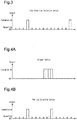
- the controller 25 responds to this and performs reception response as shown in Fig. 4A .
- the transmission circuit 26 performs responsive transmission as a reception response.
- This state is referred to as a responsive state, in which the reception circuit 29 is maintained in the standby state and a reception response is performed when trigger information is received.
- the trigger device does not perform the trigger transmission until it receives a responsive transmission or when it cannot receive a responsive transmission for a certain period of time.
- the controller 25 performs responsive transmission even when the reception circuit 29 receives information transmitted from the vehicle detection device. It is now assumed that a tire condition detection device that is always maintained in a responsive state as shown in Fig. 5B is employed. In this case, since the vehicle detection device operates regardless of responsive transmission of the tire condition detection device, the tire condition detection device may continually transmit information. Thus, the tire condition detection device that is always maintained in the responsive state continues to consume power for performing the responsive transmission.
- the controller 25 cancels the standby state of the reception circuit 29 to stop maintaining the standby state.
- the reception circuit 29 cannot receive wireless transmission from the vehicle detection device, so that no responsive transmission is performed in response to wireless transmission from the vehicle detection device. Therefore, when the reception circuit 29 is not maintained in the standby state, the tire condition detection device 21 is put in a non-responsive state, in which no responsive transmission is performed. In the non-responsive state, responsive transmission is not performed, so it can be said that responsive transmission is harder to perform than in the responsive state.
- the controller 25 switches the state of the tire condition detection device 21 from the responsive state to the non-responsive state on condition that information from the vehicle detection device is received continually.
- the trigger information transmitted from the trigger device and the information from the external device transmitted from the vehicle detection device are distinguished from each other in Figs. 4 and 5 .
- the controller 25 cannot determine whether the device that transmitted the information is the trigger device or the vehicle detection device. Therefore, even when the reception circuit 29 continually receives the trigger information, the controller 25 switches from the responsive state to the non-responsive state in the same manner.
- Switching from the non-responsive state to the responsive state is performed based on the acceleration detected by the acceleration sensor 24.
- the acceleration detected by the acceleration sensor 24 exceeds the traveling determination threshold, that is, when the controller 25 determines that the vehicle 10 is traveling, there is no possibility of continually receiving information from the vehicle detection device. In this case, the state of the tire condition detection device 21 is switched from the non-responsive state to the responsive state.
- the vehicle 10 is parked in a parking lot having the above-described vehicle detection device for 10 hours and then moved to a dealer, where the tire pressure is inspected. It is also assumed that the tire condition detection device erroneously receives wireless transmission of the vehicle detection device.
- a tire condition detection device that operates only in the responsive state.
- the tire condition detection device starts to erroneously receive the wireless transmission.
- the tire condition detection device performs responsive transmission.
- the tire condition detection device will continually perform erroneous reception and erroneous transmission (responsive transmission) for as long as 10 hours.
- the tire condition detection device continually uses power, the consumption of the power of the battery 27 increases.
- the vehicle 10 is moved to the dealer.
- the battery 27 has consumed power to perform the responsive transmission for 10 hours.
- the tire condition detection device will be incapable of wireless transmission to the receiver 30 earlier than predicted with the life of the battery.
- a tire condition detection device that can be switched from the responsive state to the non-responsive state.
- the tire condition detection device starts to erroneously receive the wireless transmission of the vehicle detection device.
- the tire condition detection device performs responsive transmission.
- the tire condition detection device is switched to the non-responsive state and will no longer use the reception function. In this case, the tire condition detection device does not even consume standby power for reception.
- the power of the battery 27 is consumed by the amount equivalent to the power that would be consumed if the vehicle did not go to the parking lot with the vehicle detection device (the power to be used for erroneous reception for four times and the power used for erroneous transmission - the reception standby power for 10 hours). Since less power of the battery 27 is consumed, the tire condition detection device can operate normally when the vehicle 10 is moved to the dealer. However, since the tire condition detection device is in the non-responsive state, no response signal is returned when the trigger device is used to inspect the tire pressure at the dealer. The dealer thus cannot inspect the tire pressure.
- the tire condition detection device 21 is employed, which can be switched from the responsive state to the non-responsive state and from the non-responsive state to the responsive state.
- the tire condition detection device 21 starts to erroneously receive the wireless transmission of the vehicle detection device.
- the tire condition detection device 21 performs responsive transmission.
- the tire condition detection device 21 is switched to the non-responsive state and will not use the reception function for as long as 10 hours. At this time, the tire condition detection device 21 does not even consume standby power for reception for as long as 10 hours.
- the power of the battery 27 is consumed by the amount equivalent to the power that would be consumed if the vehicle did not go to the parking lot with the vehicle detection device (the power to be used for erroneous reception for four times and the power used for erroneous transmission - the reception standby power for 10 hours). Since less power of the battery 27 is consumed, the tire condition detection device 21 can operate normally when the vehicle 10 is moved to the dealer. Also, when moving the vehicle 10 to the dealer, the acceleration detected by the acceleration sensor 24 exceeds the traveling determination threshold and the tire condition detection device is in the responsive state. Thus, when using the trigger device to inspect the tire pressure at the dealer, the response signal is returned and the dealer can inspect the tire pressure.
- the reception function (the reception circuit 29) of the tire condition detection device 21 is mostly used under limited circumstances such as factories and dealers. Moreover, since the vehicle user rarely uses the reception circuit 29, there is little risk of giving a disadvantage to the vehicle user.
- a tire condition detection device according to a second embodiment will now be described.
- parts that are different from the tire condition detection device of the first embodiment will be described, and the same parts as those of the first embodiment will be denoted by the same reference numerals as those of the first embodiment, and description thereof will be omitted.
- the controller 25 of the tire condition detection device 21 of the present embodiment performs the process shown in Fig. 6 at a predetermined control cycle.
- the controller 25 performs periodic measurement in step S11.
- the controller 25 obtains the condition of the tire 13 by periodically acquiring the detection results of the pressure sensor 22, the temperature sensor 23, and the acceleration sensor 24 in the periodic measurement.
- the controller 25 performs the following processing based on the detection results acquired in the periodic measurement.
- step S12 the controller 25 determines whether the tire condition detection device 21 is in a sleep state.
- the sleep state refers to a state in which periodic transmission for periodically transmitting data including the tire air pressure data, the tire internal temperature data, and the ID code from the transmission circuit 26 to the reception circuit 29 is not performed. For example, when the tire condition detection device 21 is shipped from the factory that manufactures the tire condition detection device 21, the tire condition detection device 21 is in the sleep state.
- step S20 the controller 25 maintains the reception circuit 29 of the tire condition detection device 21 in the standby state, in which the reception circuit 29 is capable of receiving wireless transmission from an external device.
- the standby state is a state in which the transmission circuit 26 performs responsive transmission as a reception response at the reception of wireless transmission.
- the sleep state is canceled.
- the sleep state is canceled by transmitting a wake-up command from a trigger device as an external device. In order to receive this wake-up command, the tire condition detection device 21 is maintained in the standby state in the sleep state.
- step S12 determines whether each of the members constituting the tire condition detection device 21 has a failure.
- a "failure" as used in this description includes a state in which the remaining amount of charge of the battery 27 is remarkably low.
- a failure is determined, for example, when the detection result stops being provided to the controller 25 from the pressure sensor 22, the temperature sensor 23, or the acceleration sensor 24, or when the voltage of the battery 27 is lower than a predetermined voltage threshold.
- step S13 If the determination result of step S13 is positive, that is, if it is determined that the tire condition detection device 21 has a failure, the controller 25 performs the process of step S20.
- the tire condition detection device 21 has a failure, the tire condition monitoring apparatus 20 does not operate normally, and the vehicle user moves the vehicle 10 to the dealer for the purpose of repairing the tire condition detection device 21 or the like.
- a trigger device is used at the dealer to transmit a response command in order to confirm the failure of the tire condition detection device 21.
- the tire condition detection device 21 In order to receive this response command, the tire condition detection device 21 is maintained in the standby state.
- step S14 the controller 25 determines whether the air pressure of the tire 13 has changed. Whether the air pressure of the tire 13 has changed is determined by determining whether the pressure detected by the pressure sensor 22 has changed by an amount greater than a change threshold within a predetermined period.
- the change threshold is set to a value greater than the value of change in the air pressure, which naturally decreases in a predetermined period due to normal traveling. Therefore, when the air pressure of the tire 13 has changed by an amount greater than the change threshold within the predetermined period, it can be determined that an anomaly has occurred in the tire 13.
- step S14 determines whether the air pressure of the tire 13 has changed.
- the controller 25 performs the process of step S20.
- the air pressure of the tire 13 changes when, for example, the tire 13 has gone flat or has been mounted to the wheel 12.
- a response command is transmitted from the trigger device to check the operation of the tire condition detection device 21 and the air pressure of the tire 13.
- the tire condition detection device 21 is maintained in the standby state.
- step S15 the controller 25 determines whether the air pressure (absolute pressure) of the tire 13 is lower than or equal to a low-pressure threshold.
- the low-pressure threshold is set to a value that is at least higher than the atmospheric pressure.
- the low-pressure threshold is set to 200 kPa (absolute pressure), which is lower than the air pressure of the tire 13 in the use region.
- step S15 If the determination result of step S15 is positive, that is, if the air pressure of the tire 13 is lower than or equal to the low-pressure threshold, the controller 25 performs the process of step S20.
- the air pressure of the tire 13 is lower than or equal to the low-pressure threshold, the tire 13 is being inspected or has gone flat, for example.
- a response command is transmitted from the trigger device for the purpose of inspecting the tire 13 and checking the operation of the tire condition detection device 21. In order to receive this response command, the tire condition detection device 21 is maintained in the standby state.
- step S15 determines whether the air pressure of the tire 13 is higher than the low-pressure threshold.
- the controller 25 performs the process of step S16.
- step S16 the tire condition detection device 21 determines whether the acceleration detected by the acceleration sensor 24 has changed.
- the acceleration detected by the acceleration sensor 24 changes when, for example, the wheel assembly 11 is replaced or the vehicle 10 is traveling. When replacing the wheel assembly 11, the wheel assembly 11 is placed horizontally so that the axial direction of the wheel assembly 11 is orthogonal to the ground.
- the acceleration sensor 24 has a plurality of detection axes and detects accelerations in the directions along the respective detection axes.
- step S16 If the determination result of step S16 is positive, that is, if the accelerations detected by the acceleration sensor 24 have changed, the controller 25 performs the process of step S20.
- an ID code registration command is transmitted from the trigger device in order to associate the wheel assembly 11 with the receiver 30.
- the tire condition detection device 21 is maintained in the standby state. Also, as described in the first embodiment, if the vehicle 10 is traveling, there is a possibility that the vehicle 10 is moving to a dealer. At the dealer, the trigger device is used to transmit a response command in order to check the operation of the tire condition detection device 21 or to inspect the tire 13 in some cases. Therefore, the tire condition detection device 21 is maintained in the standby state.
- whether the vehicle 10 is traveling is determined by utilizing changes in the centrifugal acceleration due to traveling.
- Whether the wheel assembly 11 has been replaced is determined by utilizing changes in the centrifugal acceleration due to movement of the wheel assembly 11 or changes of the component of the gravitational acceleration due to changes in the directions of the detection axes. Since the manner in which acceleration changes is different between the traveling determination of the vehicle 10 and the replacement determination of the wheel assembly 11, it is also possible to individually perform the traveling determination of the vehicle 10 and the replacement determination of the wheel assembly 11. Therefore, it is possible to maintain the tire condition detection device 21 in the standby state only when the wheel assembly 11 is replaced. It is also possible to maintain the tire condition detection device 21 in the standby state only when the vehicle 10 is traveling.
- step S30 the controller 25 performs the process of step S30. That is, the controller 25 performs the process of step S30 if the determination results of steps S12 to S16 are all negative. In contrast, the controller 25 performs the process of step S20 if at least one of the determination results of steps S12 to S16 is positive.
- step S30 if the tire condition detection device 21 is in the standby state, the controller 25 cancels the standby state. If the standby state has already been canceled, the controller 25 maintains the state in which the standby state is canceled. That is, the tire condition detection device 21 is maintained in the non-responsive state, in which wireless transmission from an external device cannot be received.
- the tire condition detection device 21 of the first embodiment switches the state of the tire condition detection device 21 from the responsive state to the non-responsive state when continually receiving information from the same external device. Also, the tire condition detection device 21 switches the state of the tire condition detection device 21 from the non-responsive state to the responsive state when the acceleration detected by the acceleration sensor 24 exceeds the travel determination threshold. Therefore, the tire condition detection device 21 is maintained in the non-responsive state only in an environment in which information from the same external device is continually received.
- the tire condition detection device 21 of the present embodiment is switched between the responsive state and the non-responsive state based on the determination results of steps S12 to S16.
- the determinations in steps S12 to S16 are made to determine whether the tire 13 and the tire condition detection device 21 are in a normal state.
- the tire condition detection device 21 is put in the non-responsive state.
- the tire condition detection device 21 is put in the responsive state only when the tire 13 and the tire condition detection device 21 are in a state different from the normal state and it is necessary to receive wireless transmission from an external device. Therefore, as compared with the tire condition detection device 21 of the first embodiment, the tire condition detection device 21 of the present embodiment is frequently maintained in the non-responsive state, and the consumption of the power of the battery 27 is easily reduced.
- a tire condition detection device according to a third embodiment will now be described.
- the transmission circuit 26 and the reception circuit 29 perform transmission/reception by using Bluetooth® Low Energy (BLE) (2.4 GHz band) as a communication method (communication standard).
- BLE Bluetooth® Low Energy
- the transmission circuit 26 and the reception circuit 29 are described as separate members. However, transmission and reception may be performed by using a transmission/reception circuit in which the transmission circuit 26 and the reception circuit 29 are integrated.
- the state of the tire condition detection device 21 is switched to the unidirectional communication state or the bidirectional communication state depending on the time for which the air pressure of the tire 13 has been maintained.
- the transmission circuit 26 transmits information at regular time intervals as in the first embodiment, and the reception circuit 29 detects information from an external device at regular time intervals.
- This state is referred to as the bidirectional communication state.
- the reception circuit 29 is maintained in a standby state to be capable of receiving wireless transmission from an external device so as to be able to receive wireless transmission from an external device.
- transmission to the receiver 30 is executed.
- the tire condition detection device 21 is maintained in the bidirectional communication state.
- the low-pressure threshold is set to a value that is at least higher than the atmospheric pressure.
- the low-pressure threshold is set to 200 kPa (absolute pressure), which is lower than the air pressure of the tire 13 in the use region.
- the air pressure of the tire 13 rises and exceeds the low-pressure threshold (at T11 in Fig. 8A ).
- the tire condition detection device 21 performs only transmission to the receiver 30.
- This state is referred to as the unidirectional communication state, in which the reception circuit 29 is not maintained in the standby state and unilaterally performs transmission to the receiver 30.
- the predetermined time is set to be longer than the time required for inspecting the tire 13 with an external device (a trigger device) after injecting air or the like into the tire 13 in a factory or the like.
- the predetermined time is set to, for example, 10 hours.
- the air When transmitting information from an external device at factories, dealers, or the like at the maintenance or the like the vehicle 10, the air is instantaneously extracted through the tire valve, so that the air pressure of the tire 13 is caused to change by an amount greater than the change threshold (at point in time T13 in Fig. 8A ).
- the change threshold is set to a value greater than the value of change in the air pressure, which naturally decreases due to normal traveling.
- the controller 25 switches the unidirectional communication state to the bidirectional communication state.
- the tire condition detection device 21 it is possible to cause the tire condition detection device 21 to receive information by instantaneously extracting air through the tire valve and transmitting information from an external device.
- a tire condition detection device that is always maintained in the bidirectional communication state repeats transmission and reception at regular time intervals (the state shown in Fig. 6 continues).
- the tire condition detection device 21 is switched from the bidirectional communication state to the unidirectional communication state in response to a change in the air pressure of the tire 13.
- the thusly configured tire condition detection device 21 performs constant transmission at regular time intervals, but does not perform reception in the unidirectional communication state. This reduces the power consumption for reception and thus extends the life of the battery 27.
- the controller 25 is capable of switching the state of the tire condition detection device 21 to the unidirectional communication state or the bidirectional communication state.
- the unidirectional communication state power is not supplied to the reception circuit 29.
- the consumption of the power of the battery 27 is reduced as compared with the case in which the tire condition detection device 21 is maintained in the bidirectional communication state. This extends the life of the battery 27.
- the controller 25 switches the state of the tire condition detection device 21 to the unidirectional communication state or the bidirectional communication state in response to a change in the air pressure of the tire 13. Therefore, it is possible to switch the state of the tire condition detection device 21, which uses BLE as the communication standard, to the unidirectional communication state or the bidirectional communication state. It is at inspection at a factory, a dealer or the like when it is desired to switch the state of the tire condition detection device 21 to the bidirectional communication state. The consumption of the power of the battery 27 is reduced by switching the state of the tire condition detection device 21 to the bidirectional communication state only during inspection at a factory, a dealer, or the like.
- the reception circuit 29 may be maintained in the standby state when the tire condition detection device 21 is in the non-responsive state.
- the reception circuit 29 receives wireless transmission from the vehicle detection device, but the controller 25 performs control so as not to perform responsive transmission even when receiving wireless transmission. Therefore, the non-responsive state may be configured such that reception response is not made regardless of whether the reception circuit 29 is maintained in the standby state.
- the state of the tire condition detection device 21 when wireless transmission from an external device is received four consecutive times, the state of the tire condition detection device 21 is switched from the responsive state to the non-responsive state.
- the number of times of consecutive reception at which the state of the tire condition detection device 21 is switched may be set to any number.
- the responsive state may be switched to the non-responsive state when wireless transmission is received five consecutive times. This number of times is set in consideration of, for example, the number of times of triggering in the factory inspection.
- the state of the tire condition detection device 21 may be switched from the bidirectional communication state to the unidirectional communication state.
- the state of the tire condition detection device 21 may be switched from non-responsive state to the responsive state.
- the change threshold and the low-pressure threshold have similar values to the change threshold and the low-pressure threshold in the second and third embodiments.
- a communication method different from RF, LF, BLE may be used as the communication method (communication standard).
- a sensor different from the temperature sensor 23, the pressure sensor 22, and the acceleration sensor 24 described in the drawings may be used as the condition detecting section.
- any one of the temperature sensor 23, the pressure sensor 22, and the acceleration sensor 24 may be used.
- a sensor other than an acceleration sensor may be used as the sensor for detecting the traveling/stopping of the vehicle 10.
- a shock sensor, an angular velocity sensor, or a magnetic sensor may be used.
- the tire condition detection device is switched between the responsive state and the non-responsive state.
- the non-responsive state may be consequently achieved by maintaining the standby state of the reception circuit 29 or reducing the frequency of execution of the response process.
- the non-responsive state may be achieved by putting the reception circuit 29 in the standby state once every 10 hours. That is, the non-responsive state is not limited to the state in which reception response is not performed, but also includes a state in which reception response is difficult to perform as compared with the responsive state (a state in which the frequency at which reception responses is possible is lower than in the case of the responsive state).
- the tire condition detection device is switched between the bidirectional communication state and the unidirectional communication state.
- the unidirectional communication state may be consequently achieved by reducing the frequency of the standby state of the reception circuit 29.
- the reception circuit 29 may be put in the standby state once every 10 hours. That is, the unidirectional communication state is not limited to a state in which the reception circuit 29 is not put in the standby state, but may be any state in which the frequency of setting the reception circuit 29 to the standby state is lower than in the bidirectional communication state.
- traveling/stopping of the vehicle 10 is detected. Instead, a signal may be transmitted from the vehicle-side when the ignition switch is turned on and the non-responsive state may be switched to the responsive state in response to the reception of that signal.
- a vehicle detection device is cited as one example of an unintended external device, the present invention is not limited to this.
- a charging facility or the like for transmitting wireless power for charging electric vehicles may be used.
Landscapes
- Engineering & Computer Science (AREA)
- Mechanical Engineering (AREA)
- Physics & Mathematics (AREA)
- General Physics & Mathematics (AREA)
- Measuring Fluid Pressure (AREA)
- Arrangements For Transmission Of Measured Signals (AREA)
- Transceivers (AREA)
Claims (4)
- Eine Reifenzustandserfassungsvorrichtung (21), welche dazu vorgesehen ist, in einem Reifen (13) einer jeweiligen Radeinheit (11) eines Fahrzeugs (10) angebracht zu werden,
wobei die Vorrichtung aufweist:- eine Zustandserfassungseinheit (22-24), die dazu vorgesehen ist, einen Zustand des Reifens zu detektieren;- eine Übermittlungseinheit (26), die dazu vorgesehen ist, von der Zustandserfassungseinheit (22-24) detektierte Informationen drahtlos zu übermitteln;- eine Empfangseinheit (29), die so eingerichtet ist, dass sie von einem externen Gerät drahtlos übermittelte Informationen empfangen kann,- eine Steuereinheit (25), die dazu vorgesehen ist, die Übermittlungseinheit (26) und die Empfangseinheit (29) zu steuern; und- eine Batterie (27), welche als Energiequelle für die Reifenzustandserfassungsvorrichtung (21) dient, wobeidie Steuereinheit (25) so eingerichtet ist, dass sie einen Zustand der Reifenzustandserfassungsvorrichtung (21) umschalten kann zwischen
einem reaktiven Zustand, in dem die Empfangseinheit (29) in einem Standby-Zustand gehalten wird, in welchem die Empfangseinheit (29) die von dem externen Gerät drahtlos übermittelten Informationen empfangen kann, wobei die Steuereinheit (25) eine Empfangsreaktion ausführt, wenn die Informationen empfangen werden, und
einem nicht-reaktiven Zustand, dadurch gekennzeichnet, dass die Empfangsreaktion schwerer auszuführen ist als in dem reaktiven Zustand, und zwar unabhängig davon, ob die Empfangseinheit (29) im Standby-Zustand gehalten wird,
der reaktive Zustand ein Zustand ist, in welchem die Empfangseinheit intermittierend betrieben wird, und
der nicht-reaktive Zustand ein Zustand ist, in welchem die Frequenz, bei der Empfangsreaktionen möglich sind, geringer ist als im Falle des reaktiven Zustands. - Die Reifenzustandserfassungsvorrichtung (21) nach Anspruch 1,
so eingerichtet, dass, wenn die Empfangseinheit (29) mehrmals die gleiche Information von dem externen Gerät empfangen hat oder wenn die Empfangseinheit (29) die Information von dem externen Gerät ununterbrochen empfangen hat, die Steuereinheit (25) den Zustand der Reifenzustandserfassungsvorrichtung (21) von dem reaktiven Zustand in den nicht-reaktiven Zustand schaltet. - Die Reifenzustandserfassungsvorrichtung (21) nach Anspruch 1 oder 2, wobei
die Zustandserfassungseinheit (22-24) einen Sensor (24) aufweist, welcher ein Fahren/Anhalten des Fahrzeugs (10) detektiert, und
die Steuereinheit (25) dazu vorgesehen ist, den Zustand der Reifenzustandserfassungsvorrichtung (21) von dem nicht-reaktiven Zustand in den reaktiven Zustand schaltet, wenn ein Fahren des Fahrzeugs (10) detektiert wird. - Die Reifenzustandserfassungsvorrichtung (21) nach Anspruch 1 oder 2, wobei
die Zustandserfassungseinheit (22-24) einen Drucksensor (22) aufweist, welcher einen Luftdruck des Reifens detektiert, und
die Steuereinheit (25) den Zustand der Reifenzustandserfassungsvorrichtung (21) von dem nicht-reaktiven Zustand in den reaktiven Zustand schaltet, wenn der von dem Drucksensor (22) detektierte Luftdruck sich um einen Betrag geändert hat, der größer ist als ein Änderungsschwellenwert, oder wenn der von dem Drucksensor (22) detektierte Luftdruck kleiner oder gleich einem Niederdruck-Schwellenwert wird.
Applications Claiming Priority (2)
| Application Number | Priority Date | Filing Date | Title |
|---|---|---|---|
| JP2015129991 | 2015-06-29 | ||
| PCT/JP2016/063210 WO2017002442A1 (ja) | 2015-06-29 | 2016-04-27 | タイヤ状態検出装置 |
Publications (3)
| Publication Number | Publication Date |
|---|---|
| EP3315330A1 EP3315330A1 (de) | 2018-05-02 |
| EP3315330A4 EP3315330A4 (de) | 2018-12-19 |
| EP3315330B1 true EP3315330B1 (de) | 2021-05-26 |
Family
ID=57608506
Family Applications (1)
| Application Number | Title | Priority Date | Filing Date |
|---|---|---|---|
| EP16817552.9A Active EP3315330B1 (de) | 2015-06-29 | 2016-04-27 | Vorrichtung zur erkennung eines reifenzustandes |
Country Status (4)
| Country | Link |
|---|---|
| US (1) | US20180361801A1 (de) |
| EP (1) | EP3315330B1 (de) |
| JP (1) | JPWO2017002442A1 (de) |
| WO (1) | WO2017002442A1 (de) |
Families Citing this family (8)
| Publication number | Priority date | Publication date | Assignee | Title |
|---|---|---|---|---|
| JP2018187981A (ja) * | 2017-04-28 | 2018-11-29 | 株式会社オートネットワーク技術研究所 | 検出装置及びタイヤ空気圧監視システム |
| US10384496B1 (en) * | 2018-02-14 | 2019-08-20 | Infineon Technologies Ag | Configuration data storage for a tire pressure sensor |
| IT201800021304A1 (it) | 2018-12-28 | 2020-06-28 | Prysmian Spa | Metodo e sistema per tracciare tamburi per cavi e della lunghezza del cavo sul tamburo. |
| JP7081043B2 (ja) * | 2019-08-29 | 2022-06-06 | 太平洋工業株式会社 | 送信機、受信機、及び送受信システム |
| WO2021251943A1 (en) * | 2020-06-08 | 2021-12-16 | Sensata Technologies Inc. | Vehicle sensor learning using a low power wake-up receiver |
| US12479245B2 (en) * | 2021-12-16 | 2025-11-25 | Sensata Technologies, Inc. | Tire monitor with close proximity connectivity |
| TW202419305A (zh) * | 2022-11-09 | 2024-05-16 | 系統電子工業股份有限公司 | 2.4g訊號編碼喚醒運作的胎壓偵測器 |
| CN118560200A (zh) * | 2024-06-20 | 2024-08-30 | 保隆霍富(上海)电子有限公司 | 射频广播信号的控制方法和装置、胎压监测系统 |
Family Cites Families (11)
| Publication number | Priority date | Publication date | Assignee | Title |
|---|---|---|---|---|
| JP2003517231A (ja) * | 1999-12-15 | 2003-05-20 | ザ・グッドイヤー・タイヤ・アンド・ラバー・カンパニー | 応答機のためのプログラマブルトリマ |
| CA2676101C (en) * | 2000-07-26 | 2016-12-06 | Bridgestone/Firestone, Inc. | Electronic tire management system |
| US8266465B2 (en) * | 2000-07-26 | 2012-09-11 | Bridgestone Americas Tire Operation, LLC | System for conserving battery life in a battery operated device |
| JP4351398B2 (ja) * | 2001-01-15 | 2009-10-28 | 株式会社ケンウッド | 移動体電話機 |
| JP2003248890A (ja) * | 2002-02-22 | 2003-09-05 | Pacific Ind Co Ltd | タイヤ状態監視装置 |
| JP4347601B2 (ja) * | 2003-04-14 | 2009-10-21 | 横浜ゴム株式会社 | 車輪情報取得システムおよび車輪の装着位置情報設定装置 |
| AU2005254356B2 (en) * | 2004-06-16 | 2008-08-07 | Bridgestone Corporation | Tire management system |
| US7637105B2 (en) * | 2005-04-04 | 2009-12-29 | Telezygology Inc. | Smart memory alloy control |
| JP4650077B2 (ja) * | 2005-04-20 | 2011-03-16 | トヨタ自動車株式会社 | 車輪状態取得装置 |
| JP2014091344A (ja) * | 2012-10-31 | 2014-05-19 | Yokohama Rubber Co Ltd:The | タイヤ状態監視システムおよび監視装置 |
| US20160375733A1 (en) * | 2014-03-10 | 2016-12-29 | Itire, Llc | Smart tag assembly for mounting on an object to be tracked |
-
2016
- 2016-04-27 JP JP2017526207A patent/JPWO2017002442A1/ja active Pending
- 2016-04-27 WO PCT/JP2016/063210 patent/WO2017002442A1/ja not_active Ceased
- 2016-04-27 US US15/739,142 patent/US20180361801A1/en not_active Abandoned
- 2016-04-27 EP EP16817552.9A patent/EP3315330B1/de active Active
Non-Patent Citations (1)
| Title |
|---|
| None * |
Also Published As
| Publication number | Publication date |
|---|---|
| EP3315330A4 (de) | 2018-12-19 |
| JPWO2017002442A1 (ja) | 2018-05-24 |
| WO2017002442A1 (ja) | 2017-01-05 |
| EP3315330A1 (de) | 2018-05-02 |
| US20180361801A1 (en) | 2018-12-20 |
Similar Documents
| Publication | Publication Date | Title |
|---|---|---|
| EP3315330B1 (de) | Vorrichtung zur erkennung eines reifenzustandes | |
| US7391308B2 (en) | Monitoring device, transceiver system and its control method | |
| US20140002258A1 (en) | Smart tire pressure sensor, smart tire pressure monitoring system using same | |
| US7394357B2 (en) | Wheel condition determination apparatus | |
| US9776461B2 (en) | Tire inflation pressure detection device | |
| US11298990B2 (en) | Tire pressure monitoring system | |
| US9950578B2 (en) | Tire air pressure detection device | |
| US11390125B2 (en) | Wheel registration apparatus and tire pressure monitoring system including the same | |
| EP3521069A1 (de) | Sender und reifenzustandüberwachungsvorrichtung | |
| US9162540B2 (en) | Apparatus for tire pressure monitoring, information transmissing method thereof and integrated receiver system | |
| US20180361802A1 (en) | Method for adapting the strategy for acquiring measurements of radial acceleration of the wheels of a vehicle | |
| EP2562012A1 (de) | Ventil-ID-Registrierungssystem | |
| KR101850638B1 (ko) | 차륜 회전위치 특정장치 | |
| JP2012040925A (ja) | センサユニット、及びタイヤ空気圧監視システムのセンサユニット登録方法 | |
| JP2006021716A (ja) | タイヤ空気圧モニター装置 | |
| US20120262286A1 (en) | Smart tire-pressure sensing system and automatic matching method thereof | |
| JP5772285B2 (ja) | 自車両信号判別装置およびそれを備えたタイヤ空気圧検出装置 | |
| US20120262285A1 (en) | Smart tire-pressure sensing system with protection mechanism and protection method thereof | |
| US11052711B2 (en) | Electronic wheel unit for a vehicle wheel | |
| JP2012250685A (ja) | タイヤ空気圧監視システム及びタイヤバルブ | |
| EP1502773B1 (de) | Externer Signalgeber, Fahrzeugzustandserfassungssystem und Verfahren zur externen Signalerzeugung | |
| JP3951947B2 (ja) | タイヤ空気圧検出装置 | |
| JP6027043B2 (ja) | タイヤ状態監視装置 | |
| KR101745003B1 (ko) | 타이어 압력 감지 장치 및 그 방법 | |
| US20060041344A1 (en) | Monitoring apparatus and method for handling detected results of a monitored object |
Legal Events
| Date | Code | Title | Description |
|---|---|---|---|
| STAA | Information on the status of an ep patent application or granted ep patent |
Free format text: STATUS: THE INTERNATIONAL PUBLICATION HAS BEEN MADE |
|
| PUAI | Public reference made under article 153(3) epc to a published international application that has entered the european phase |
Free format text: ORIGINAL CODE: 0009012 |
|
| STAA | Information on the status of an ep patent application or granted ep patent |
Free format text: STATUS: REQUEST FOR EXAMINATION WAS MADE |
|
| 17P | Request for examination filed |
Effective date: 20171222 |
|
| AK | Designated contracting states |
Kind code of ref document: A1 Designated state(s): AL AT BE BG CH CY CZ DE DK EE ES FI FR GB GR HR HU IE IS IT LI LT LU LV MC MK MT NL NO PL PT RO RS SE SI SK SM TR |
|
| AX | Request for extension of the european patent |
Extension state: BA ME |
|
| DAV | Request for validation of the european patent (deleted) | ||
| DAX | Request for extension of the european patent (deleted) | ||
| A4 | Supplementary search report drawn up and despatched |
Effective date: 20181116 |
|
| RIC1 | Information provided on ipc code assigned before grant |
Ipc: G01L 17/00 20060101ALI20181112BHEP Ipc: B60C 23/04 20060101AFI20181112BHEP Ipc: H04B 1/401 20150101ALI20181112BHEP |
|
| GRAP | Despatch of communication of intention to grant a patent |
Free format text: ORIGINAL CODE: EPIDOSNIGR1 |
|
| STAA | Information on the status of an ep patent application or granted ep patent |
Free format text: STATUS: GRANT OF PATENT IS INTENDED |
|
| INTG | Intention to grant announced |
Effective date: 20201216 |
|
| RIN1 | Information on inventor provided before grant (corrected) |
Inventor name: OKUMURA, KOJI Inventor name: FUJII, KEIYU |
|
| GRAS | Grant fee paid |
Free format text: ORIGINAL CODE: EPIDOSNIGR3 |
|
| GRAA | (expected) grant |
Free format text: ORIGINAL CODE: 0009210 |
|
| STAA | Information on the status of an ep patent application or granted ep patent |
Free format text: STATUS: THE PATENT HAS BEEN GRANTED |
|
| AK | Designated contracting states |
Kind code of ref document: B1 Designated state(s): AL AT BE BG CH CY CZ DE DK EE ES FI FR GB GR HR HU IE IS IT LI LT LU LV MC MK MT NL NO PL PT RO RS SE SI SK SM TR |
|
| REG | Reference to a national code |
Ref country code: GB Ref legal event code: FG4D |
|
| REG | Reference to a national code |
Ref country code: CH Ref legal event code: EP |
|
| REG | Reference to a national code |
Ref country code: AT Ref legal event code: REF Ref document number: 1395852 Country of ref document: AT Kind code of ref document: T Effective date: 20210615 |
|
| REG | Reference to a national code |
Ref country code: DE Ref legal event code: R096 Ref document number: 602016058525 Country of ref document: DE |
|
| REG | Reference to a national code |
Ref country code: IE Ref legal event code: FG4D |
|
| REG | Reference to a national code |
Ref country code: LT Ref legal event code: MG9D |
|
| REG | Reference to a national code |
Ref country code: AT Ref legal event code: MK05 Ref document number: 1395852 Country of ref document: AT Kind code of ref document: T Effective date: 20210526 |
|
| PG25 | Lapsed in a contracting state [announced via postgrant information from national office to epo] |
Ref country code: HR Free format text: LAPSE BECAUSE OF FAILURE TO SUBMIT A TRANSLATION OF THE DESCRIPTION OR TO PAY THE FEE WITHIN THE PRESCRIBED TIME-LIMIT Effective date: 20210526 Ref country code: AT Free format text: LAPSE BECAUSE OF FAILURE TO SUBMIT A TRANSLATION OF THE DESCRIPTION OR TO PAY THE FEE WITHIN THE PRESCRIBED TIME-LIMIT Effective date: 20210526 Ref country code: BG Free format text: LAPSE BECAUSE OF FAILURE TO SUBMIT A TRANSLATION OF THE DESCRIPTION OR TO PAY THE FEE WITHIN THE PRESCRIBED TIME-LIMIT Effective date: 20210826 Ref country code: LT Free format text: LAPSE BECAUSE OF FAILURE TO SUBMIT A TRANSLATION OF THE DESCRIPTION OR TO PAY THE FEE WITHIN THE PRESCRIBED TIME-LIMIT Effective date: 20210526 Ref country code: FI Free format text: LAPSE BECAUSE OF FAILURE TO SUBMIT A TRANSLATION OF THE DESCRIPTION OR TO PAY THE FEE WITHIN THE PRESCRIBED TIME-LIMIT Effective date: 20210526 |
|
| REG | Reference to a national code |
Ref country code: NL Ref legal event code: MP Effective date: 20210526 |
|
| PG25 | Lapsed in a contracting state [announced via postgrant information from national office to epo] |
Ref country code: PL Free format text: LAPSE BECAUSE OF FAILURE TO SUBMIT A TRANSLATION OF THE DESCRIPTION OR TO PAY THE FEE WITHIN THE PRESCRIBED TIME-LIMIT Effective date: 20210526 Ref country code: NO Free format text: LAPSE BECAUSE OF FAILURE TO SUBMIT A TRANSLATION OF THE DESCRIPTION OR TO PAY THE FEE WITHIN THE PRESCRIBED TIME-LIMIT Effective date: 20210826 Ref country code: PT Free format text: LAPSE BECAUSE OF FAILURE TO SUBMIT A TRANSLATION OF THE DESCRIPTION OR TO PAY THE FEE WITHIN THE PRESCRIBED TIME-LIMIT Effective date: 20210927 Ref country code: SE Free format text: LAPSE BECAUSE OF FAILURE TO SUBMIT A TRANSLATION OF THE DESCRIPTION OR TO PAY THE FEE WITHIN THE PRESCRIBED TIME-LIMIT Effective date: 20210526 Ref country code: RS Free format text: LAPSE BECAUSE OF FAILURE TO SUBMIT A TRANSLATION OF THE DESCRIPTION OR TO PAY THE FEE WITHIN THE PRESCRIBED TIME-LIMIT Effective date: 20210526 Ref country code: IS Free format text: LAPSE BECAUSE OF FAILURE TO SUBMIT A TRANSLATION OF THE DESCRIPTION OR TO PAY THE FEE WITHIN THE PRESCRIBED TIME-LIMIT Effective date: 20210926 Ref country code: GR Free format text: LAPSE BECAUSE OF FAILURE TO SUBMIT A TRANSLATION OF THE DESCRIPTION OR TO PAY THE FEE WITHIN THE PRESCRIBED TIME-LIMIT Effective date: 20210827 Ref country code: LV Free format text: LAPSE BECAUSE OF FAILURE TO SUBMIT A TRANSLATION OF THE DESCRIPTION OR TO PAY THE FEE WITHIN THE PRESCRIBED TIME-LIMIT Effective date: 20210526 |
|
| PG25 | Lapsed in a contracting state [announced via postgrant information from national office to epo] |
Ref country code: NL Free format text: LAPSE BECAUSE OF FAILURE TO SUBMIT A TRANSLATION OF THE DESCRIPTION OR TO PAY THE FEE WITHIN THE PRESCRIBED TIME-LIMIT Effective date: 20210526 |
|
| PG25 | Lapsed in a contracting state [announced via postgrant information from national office to epo] |
Ref country code: SK Free format text: LAPSE BECAUSE OF FAILURE TO SUBMIT A TRANSLATION OF THE DESCRIPTION OR TO PAY THE FEE WITHIN THE PRESCRIBED TIME-LIMIT Effective date: 20210526 Ref country code: SM Free format text: LAPSE BECAUSE OF FAILURE TO SUBMIT A TRANSLATION OF THE DESCRIPTION OR TO PAY THE FEE WITHIN THE PRESCRIBED TIME-LIMIT Effective date: 20210526 Ref country code: RO Free format text: LAPSE BECAUSE OF FAILURE TO SUBMIT A TRANSLATION OF THE DESCRIPTION OR TO PAY THE FEE WITHIN THE PRESCRIBED TIME-LIMIT Effective date: 20210526 Ref country code: ES Free format text: LAPSE BECAUSE OF FAILURE TO SUBMIT A TRANSLATION OF THE DESCRIPTION OR TO PAY THE FEE WITHIN THE PRESCRIBED TIME-LIMIT Effective date: 20210526 Ref country code: DK Free format text: LAPSE BECAUSE OF FAILURE TO SUBMIT A TRANSLATION OF THE DESCRIPTION OR TO PAY THE FEE WITHIN THE PRESCRIBED TIME-LIMIT Effective date: 20210526 Ref country code: CZ Free format text: LAPSE BECAUSE OF FAILURE TO SUBMIT A TRANSLATION OF THE DESCRIPTION OR TO PAY THE FEE WITHIN THE PRESCRIBED TIME-LIMIT Effective date: 20210526 Ref country code: EE Free format text: LAPSE BECAUSE OF FAILURE TO SUBMIT A TRANSLATION OF THE DESCRIPTION OR TO PAY THE FEE WITHIN THE PRESCRIBED TIME-LIMIT Effective date: 20210526 |
|
| REG | Reference to a national code |
Ref country code: DE Ref legal event code: R097 Ref document number: 602016058525 Country of ref document: DE |
|
| PLBE | No opposition filed within time limit |
Free format text: ORIGINAL CODE: 0009261 |
|
| STAA | Information on the status of an ep patent application or granted ep patent |
Free format text: STATUS: NO OPPOSITION FILED WITHIN TIME LIMIT |
|
| 26N | No opposition filed |
Effective date: 20220301 |
|
| PG25 | Lapsed in a contracting state [announced via postgrant information from national office to epo] |
Ref country code: IS Free format text: LAPSE BECAUSE OF FAILURE TO SUBMIT A TRANSLATION OF THE DESCRIPTION OR TO PAY THE FEE WITHIN THE PRESCRIBED TIME-LIMIT Effective date: 20210926 Ref country code: AL Free format text: LAPSE BECAUSE OF FAILURE TO SUBMIT A TRANSLATION OF THE DESCRIPTION OR TO PAY THE FEE WITHIN THE PRESCRIBED TIME-LIMIT Effective date: 20210526 |
|
| PG25 | Lapsed in a contracting state [announced via postgrant information from national office to epo] |
Ref country code: IT Free format text: LAPSE BECAUSE OF FAILURE TO SUBMIT A TRANSLATION OF THE DESCRIPTION OR TO PAY THE FEE WITHIN THE PRESCRIBED TIME-LIMIT Effective date: 20210526 |
|
| REG | Reference to a national code |
Ref country code: CH Ref legal event code: PL |
|
| REG | Reference to a national code |
Ref country code: BE Ref legal event code: MM Effective date: 20220430 |
|
| PG25 | Lapsed in a contracting state [announced via postgrant information from national office to epo] |
Ref country code: MC Free format text: LAPSE BECAUSE OF FAILURE TO SUBMIT A TRANSLATION OF THE DESCRIPTION OR TO PAY THE FEE WITHIN THE PRESCRIBED TIME-LIMIT Effective date: 20210526 Ref country code: LU Free format text: LAPSE BECAUSE OF NON-PAYMENT OF DUE FEES Effective date: 20220427 Ref country code: LI Free format text: LAPSE BECAUSE OF NON-PAYMENT OF DUE FEES Effective date: 20220430 Ref country code: CH Free format text: LAPSE BECAUSE OF NON-PAYMENT OF DUE FEES Effective date: 20220430 |
|
| PG25 | Lapsed in a contracting state [announced via postgrant information from national office to epo] |
Ref country code: BE Free format text: LAPSE BECAUSE OF NON-PAYMENT OF DUE FEES Effective date: 20220430 |
|
| PG25 | Lapsed in a contracting state [announced via postgrant information from national office to epo] |
Ref country code: IE Free format text: LAPSE BECAUSE OF NON-PAYMENT OF DUE FEES Effective date: 20220427 |
|
| PG25 | Lapsed in a contracting state [announced via postgrant information from national office to epo] |
Ref country code: HU Free format text: LAPSE BECAUSE OF FAILURE TO SUBMIT A TRANSLATION OF THE DESCRIPTION OR TO PAY THE FEE WITHIN THE PRESCRIBED TIME-LIMIT; INVALID AB INITIO Effective date: 20160427 |
|
| PG25 | Lapsed in a contracting state [announced via postgrant information from national office to epo] |
Ref country code: MK Free format text: LAPSE BECAUSE OF FAILURE TO SUBMIT A TRANSLATION OF THE DESCRIPTION OR TO PAY THE FEE WITHIN THE PRESCRIBED TIME-LIMIT Effective date: 20210526 Ref country code: CY Free format text: LAPSE BECAUSE OF FAILURE TO SUBMIT A TRANSLATION OF THE DESCRIPTION OR TO PAY THE FEE WITHIN THE PRESCRIBED TIME-LIMIT Effective date: 20210526 |
|
| PG25 | Lapsed in a contracting state [announced via postgrant information from national office to epo] |
Ref country code: MT Free format text: LAPSE BECAUSE OF FAILURE TO SUBMIT A TRANSLATION OF THE DESCRIPTION OR TO PAY THE FEE WITHIN THE PRESCRIBED TIME-LIMIT Effective date: 20210526 |
|
| PGFP | Annual fee paid to national office [announced via postgrant information from national office to epo] |
Ref country code: FR Payment date: 20250310 Year of fee payment: 10 |
|
| PGFP | Annual fee paid to national office [announced via postgrant information from national office to epo] |
Ref country code: GB Payment date: 20250306 Year of fee payment: 10 |
|
| PGFP | Annual fee paid to national office [announced via postgrant information from national office to epo] |
Ref country code: DE Payment date: 20250305 Year of fee payment: 10 |
|
| REG | Reference to a national code |
Ref country code: DE Ref legal event code: R082 Ref document number: 602016058525 Country of ref document: DE Representative=s name: DAUB PARTG MBB, DE |
|
| PG25 | Lapsed in a contracting state [announced via postgrant information from national office to epo] |
Ref country code: TR Free format text: LAPSE BECAUSE OF FAILURE TO SUBMIT A TRANSLATION OF THE DESCRIPTION OR TO PAY THE FEE WITHIN THE PRESCRIBED TIME-LIMIT Effective date: 20210526 |